Liquid Regions of Lanthanum-Bearing Aluminosilicates


1
Key Laboratory of Extraordinary Bond Engineering and Advanced Materials Technology (EBEAM), Yangtze Normal University, Chongqing 408100, China
2
Key Laboratory of Ecological Utilization of Multi-Metallic Mineral of Education Ministry, Northeastern University, Shenyang 110819, China
3
National Center for International Research of Clean Metallurgy, Central South University, Changsha 410083, China
*
Author to whom correspondence should be addressed.
Materials 2020, 13(2), 450; https://0-doi-org.brum.beds.ac.uk/10.3390/ma13020450
Submission received: 29 November 2019
/
Revised: 9 January 2020
/
Accepted: 14 January 2020
/
Published: 17 January 2020
/
Corrected: 18 February 2024
(This article belongs to the Special Issue Rare Earth Oxides and Their Applications)
Abstract
:The Al2O3-SiO2, La2O3-Al2O3, and La2O3-SiO2 binary phase diagrams were estimated by Redlich–Kister expression. La4.67Si3O13 (=La4.67(SiO4)3O) was introduced to improve the existing phase diagrams. The Al2O3-SiO2-La2O3 ternary phase diagram extrapolated by Kohler method was optimized. Then, the liquidus of Al2O3-SiO2-La2O3 system at 1600 °C was compared with Al2O3-SiO2-RE2O3 (RE = Rare Earth Elements) systems and experimental results in other literature. The high temperature experiments were conducted in the tube furnace at 1500 °C. Then the field emission scanning electron microscope (FE-SEM), energy dispersive spectrometer (EDS), and X-ray diffraction (XRD) were employed to verify the calculated liquid region and precipitates phase at 1500 °C. Moreover, the liquidus of binary systems were compared with FactSage results and experiments. The optimized ternary phase diagram shows the relatively reliable region of liquid phase, and it is significant to the seal glass of solid oxide fuel cells and other fields being related to RE containing silicates.
1. Introduction
Aluminosilicate glasses containing rare-earth (RE) elements have been suggested for various applications owing to its favorable chemical, mechanical and optical properties and so on [1,2,3]. They can constitute host materials in optical devices and are proposed for radioactive waste-storage [4]. Moreover, RE-bearing silicate glass is the favorable material to be the seal glass for solid oxide fuel cells (SOFC) owing to the critical thermal properties [5]. RE2O3-Al2O3-SiO2 systems reveal relatively wide glass formation regions when prepared from melts of given compositions between approximately 1500 °C and 2000 °C [6,7]. To well understand the glass formation region and the associated microstructure and reaction thermodynamics of the mentioned system, an explicit phase diagram of RE2O3-Al2O3-SiO2 systems can provide precise information of these. However, few of experimental data of the phase diagrams are available to present the liquid region (homogeneous glass formation region) in RE2O3-Al2O3-SiO2 systems (RE elements are mainly La [8], Y [9,10,11,12] and Gd [11,12]) and the nonstoichiometric phases in each binary system. Mullite and spinel are always formed simultaneously or in order in the Al2O3-SiO2 system [13]. The oxyapatite phase is found in the La2O3-SiO2 system [14]. The RE2O3-Al2O3-SiO2 systems (RE = Nd, Sm, Gd and La) were computed by simplified thermodynamic properties associating with symmetric extrapolated expression [15,16,17]. Nevertheless, the liquid region of La2O3-Al2O3-SiO2 system is much different from the experimental results given by Iftekhar [18]. Only limited publications can be consulted about the isothermal section information of the La2O3-Al2O3-SiO2 system diagram, not to mention the projection map. The phase diagram of La2O3-Al2O3-SiO2 system cannot be worked out by any thermodynamic software by now as a result of lacking parameters of mixed solution. Therefore, the primary task of the present work is to determine the liquid region and precipitates at high temperature (≥1500 °C) of possible glass formation, whereas the solid solutions found at 1300 °C by Mazza [8] was not considered in the present work because the temperature is low and there is no homogeneous glass formation.
A plenty of optimized systematic phase diagrams have been worked out by Computer Coupling of Phase Diagrams and Thermochemistry (CALPHAD) technique based on various solution models, which are released to describe the solution phase, such as regular solution model, sublattice model and quasi-chemical model and so on. In addition, a variety of empirical or mathematical expressions, such as Margules, Redlich–Kister, and Bale–Pletion expressions, are generated during the process of development. In the present work, the Redlich–Kister [19] expression based on the subregular solution model was adopted to calculate the Al2O3-SiO2, A2O3-La2O3, and La2O3-SiO2 binary systems, and the La2O3-Al2O3-SiO2 ternary system was extrapolated by Kohler method [20]. Then the optimized ternary system phase diagram was critically assessed by comparing with existing experimental results. The obtained ternary phase diagram is providing a theoretical basis for the glass production process and other fields, such as metallurgical flux preparation and green comprehensive utilization of complex cogenetic ore containing rare earth elements.
2. Calculation Method and Experimental Procedure
The phase boundary lines in phase diagrams are definitely drawn by connecting a series of equilibrium points at the given temperature and pressure. Every equilibrium point is carefully calculated based on the total Gibbs principle of minimum free energy under some constraints. The totally absolute Gibbs free energy of mixed system can be written as
where xi is the mole fraction of component i; is the standard Gibbs free energy of pure substance i, J·mol−1; R is the gas constant, 8.314 J mol−1·K−1; T is the temperature, Kelvin; and GE is excess Gibbs free energy, J·mol−1.
The can be derived by Gibbs–Helmholtz expression, G = H − TS, from essential thermodynamic properties, such as standard enthalpy, standard entropy and isobaric heat capacity. The referable data mentioned above related to the base members in this work are listed in Table 1. For some substances such as LaAlO3 of which applicable temperature is out of the scope for direct calculation, the extrapolation based on the Cp expression is adopted in the current optimization process.
GE in Equation (1) is the most important parameter to represent the interaction of components except for entropy value increase contributed by ideal mixture. In the present work, it can be obtained in the binary system by the Redlich–Kister expression as follows,
where Lj (j = 0, 1, 2, …) is the interaction energy or interaction parameter between two end members. It can be written in the general form of Gibbs free energy as follows,
where a, b, c, d, e, and f are the constant parameters usually obtained through empirical or semi-empirical method. Only the first two parameters a and b are considered and optimized later in this work as the deviation is acceptable in this situation.
The commercial software FactSage 7.1 which is popular in phase diagram optimization by CALPHAD technique was applied to conduct the optimization process and also used to draw the final phase diagrams according to the user-define database. All the thermodynamic properties in Table 1 were included in the user-define database. The data of solid solution phase “mullite” was chosen from the FToxid database which is strong in the calculations of mixed oxides systems. These existing experimental data in the available literature, such as liquidus temperature and activity, were adopted to assess the calculation results in the binary phase diagrams. The modules, Solution, Equilib, Phase Diagram, and OptiSage, were employed to achieve the parameters optimization and phase diagrams calculation. Then, the calculated data points were export to the software Origin 8.5 to draw the phase diagram comparing with the reference data points or experimental results. Moreover, the optimized binary phase diagrams Al2O3-SiO2 and La2O3-Al2O3 systems were compared with the results computed by FactSage 7.1 where the FToxid database was employed. And the activity curves of CaO and Al2O3 in the Al2O3-SiO2 system were compared with the limited experimental points at 1877 °C (2150 K).
After the GE values of binary phase diagrams were obtained, the extrapolation portion of La2O3-Al2O3-SiO2 ternary phase diagram was derived by Kohler method. Considering that the results calculated by extrapolation methods are not accurate enough, an additional GE parameter optimized from the ternary eutectic temperature of La2O3-Al2O3-SiO2 system was introduced to correct the deviation.
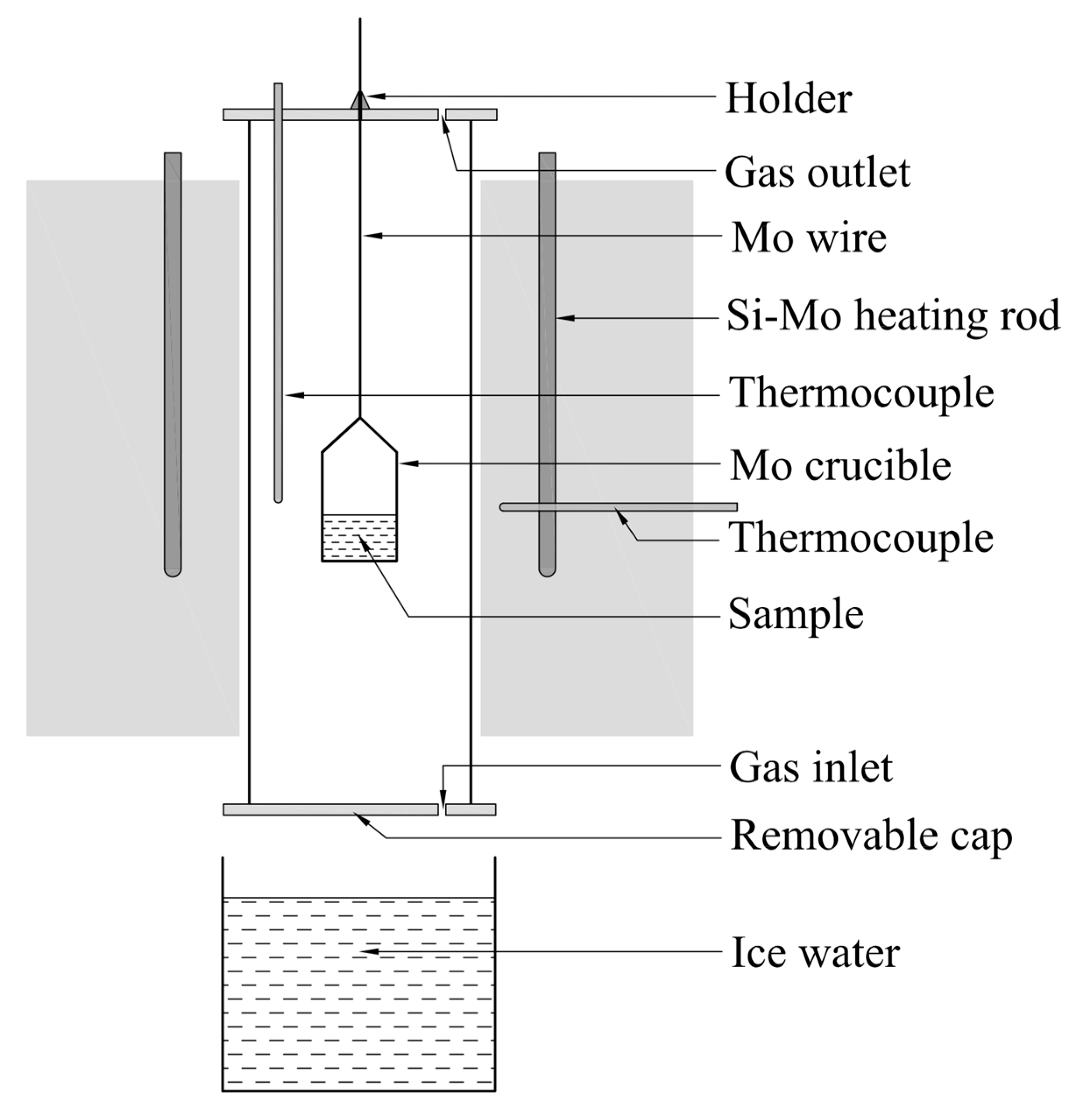
When the ternary phase diagram of La2O3-Al2O3-SiO2 system were worked out, the liquid region of the system at 1600 °C was compared with the experimental results in published references. At the same time, validation experiments of liquid region at 1500 °C were carried out in a tube furnace heated by MoSi2 rods, the schematic of which is shown as Figure 1.
The Al2O3, SiO2, and La2O3 powders with the purity of 4 N supplied by Sinopharm Chemical Reagent Company were pretreated in the Muffle furnace at 1000 °C for 2 h to remove moisture, impurity and volatiles. Then the material powders were grinded and sieved. The particles with the size less than 74 μm were intensively mixed in the agate mortar at the given mole ratios (as the 18 experimental points marked in the figures later). One gram of individual sample was taken from the evenly mixed powders and then transferred into a Mo crucible with the inner diameter of 1 cm and wall thickness of 1 mm. The powdered sample in the Mo crucible was compacted by the glass road and then pricked with stainless steel needle to make holes to avoid eruption during the heating process. Afterwards, the Mo crucible hung by the Mo wire was placed into a tube furnace at ambient temperature under argon atmosphere at a flow rate of 5.0 L·min−1. Then, the furnace was heated up and held at 1600 °C for 1 h to pre-melting and to ensure the totally uniformity of the sample at good flow conditions. Thereafter, the furnace temperature was slowly decreased to 1500 °C and held for 2 h. Subsequently, the holder at the top side of furnace was loosened and the sample rapidly fall under gravity to be quenched into ice water from 1500 °C to 0 °C through the bottom side of furnace as shown in Figure 1. The obtained sample was mounted in the ethoxyline resin and polished by various scale of abrasive paper and polishing cloth in order under the aid of grinding paste SiC. Gold powder was sprayed on the polished surface of sample to ensure the electrical conductivity before the following analysis. Finally, the FE-SEM with EDS and XRD were used to determine the morphology, chemical composition and mineral phase of the quenched sample.
3. Results and Discussion
3.1. Binary Phase Diagram of Al2O3-SiO2-La2O3 System
When the Redlich–Kister expression based on subregular solution model and Kohler method were employed to optimize all the binary systems, the related interaction parameters were worked out and are listed in Table 2 and all the binary phase diagrams are present in Figure 2.
3.1.1. The SiO2-Al2O3 System
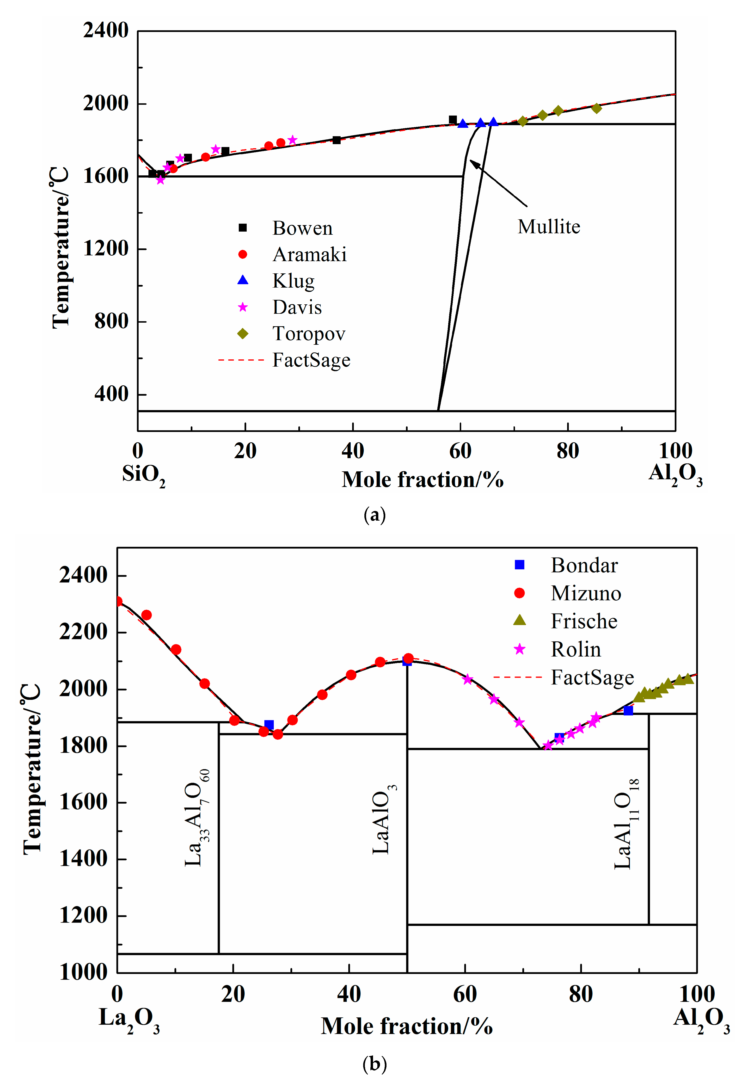
To study the stable phases in the SiO2-Al2O3 system, various models were introduced and the “mullite” region was considered as solution phase or pure substance in previous researches. In 1979, the SiO2-Al2O3 phase diagram was calculated by DÖrner using regular solution model [28]. However, the liquidus was different from the available experimental results. Thereafter, the Gibbs free energy of mixing liquid was introduced using an associated solution model by Ball in 1993 [29]. The mullite region is in good agreement with the experimental results. At the same time, Eriksson conducted the calculation using modified quasi-chemical model [30] and the results were acceptable. In 2005, the two-sublattice model was adopted to calculate the SiO2-Al2O3 system and the optimized results coincide well with the experimental data. Besides, when the mullite was considered as pure substance, the calculated liquidus of Al2O3-SiO2 system showed more accuracy [15,31]. In present work, the mullite data form FactSage database was introduced and the solution phase was calculated by Redlich–Kister expression. The calculated SiO2-Al2O3 phase diagram was shown as Figure 2a [32,33,34,35,36]. The dash line in Figure 2a is the liquidus worked out by FactSage 7.1 when the solution phase was chosen form FToxide database. It is obvious that the liquid region calculated by Redlich–Kister expression is almost the same as the FactSage result. In addition, the experimental points employed conformably meet the calculated liquidus.
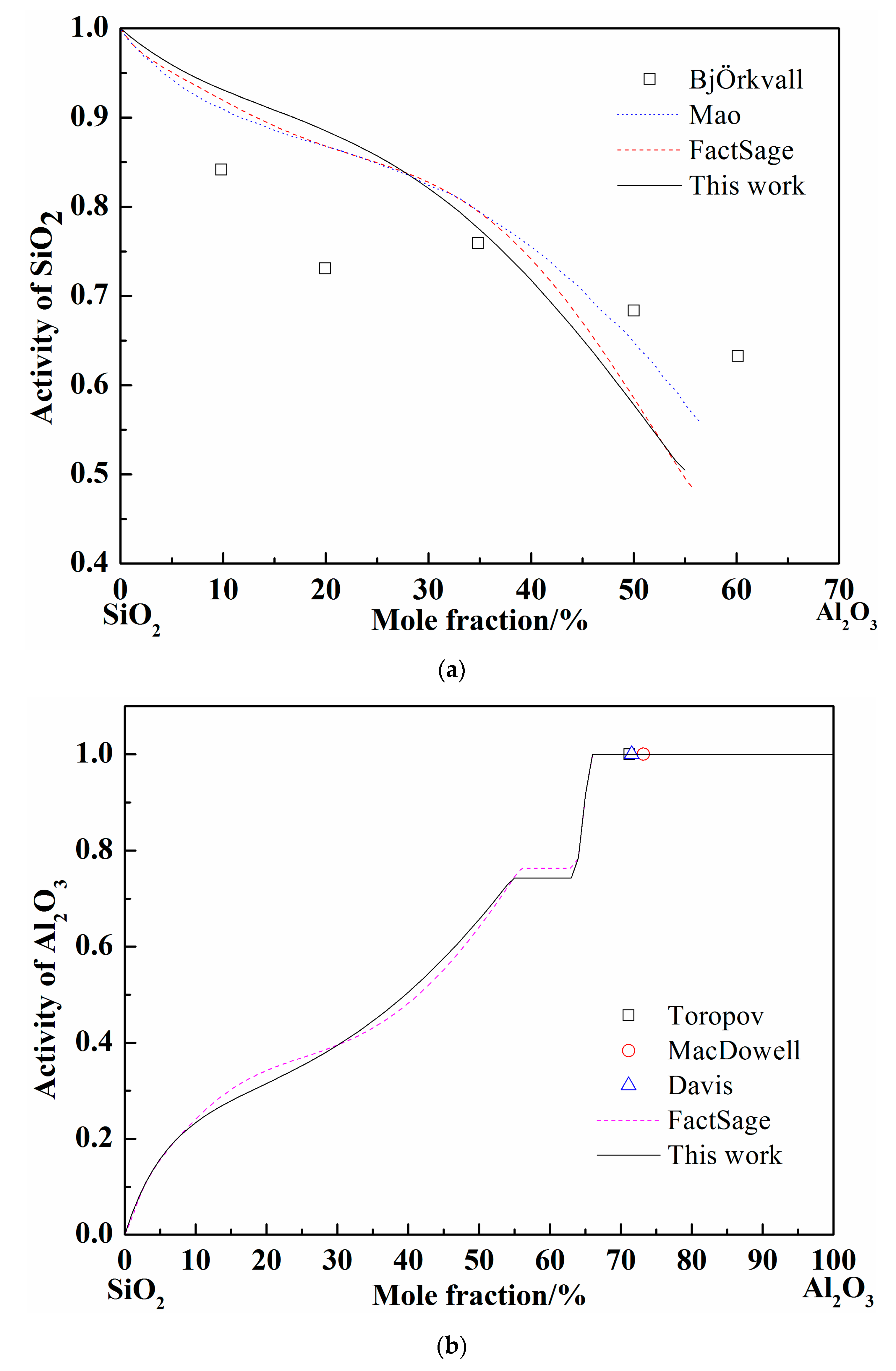
When the pure liquid phase was chosen as the standard state, the activity of SiO2 was calculated and compared with the FactSage and others’ results at 1877 °C, as shown in Figure 3a [37,38]. The activity of SiO2 worked out by different calculation (Mao, FactSage, and present work) adopted different models are nearly coincident. The calculated curves show the same tendency with the experimental results by BjÖkvall et al. Figure 3b shows the calculation results of Al2O3 activity at 1877 °C [36,37,39], when the pure solid phase was chosen as the standard state. The experimental points by Toropov et al. show the pure solid Al2O3 formation site as the Al2O3 content increase at 1877 °C and the Al2O3 activity is definitely 1. The variation trend of Al2O3 activity calculated by FactSage and in present work are consistent and the activity value reaches 1 at the same point (66% of Al2O3 in mole fraction). Generally, the optimized SiO2-Al2O3 system by Redlich–Kister expression is accurate according to the above comparison.
3.1.2. The La2O3-Al2O3 System
Only a few of experimental studies and calculations on the phase diagram La2O3-Al2O3 system are published so far. The La2O3-Al2O3 phase diagram was calculated using quasi-chemical model by Wu in 1992 [20], and using Redlich–Kister expression by Li [15]. However, the fusion enthalpy and entropy in the work of Li et al. are simplified to temperature-independent constants. The more precise thermodynamic properties should be introduced, and the La2O3-Al2O3 system was calculated by Redlich–Kister expression. The calculation results and the experimental points in the present work are shown in Figure 2b [40,41,42,43]. The FactSage results and all the experimental points by former scholars were almost coincided with the current calculated liquidus, which indicates the reliability of optimized binary phase diagram of La2O3-Al2O3 system.
3.1.3. The La2O3-SiO2 System
The La2O3-SiO2 system is rarely studied by experiment or simulation, and different opinions on the intermediate phases have always been there. In 1961, Toropov released the La2O3-SiO2 phase diagram, and the intermediate compounds are La2Si2O7, La2SiO5, and La4Si3O12. In 1982, Bondar, from the same research group as Toropov, modified the La4Si3O12 phase to La4.67Si3O13. Li finished the calculated La2O3-SiO2 system employing simplified thermodynamic properties in 1999 [11]. However, the adoptive compound was La4Si3O12. Kim only calculated the two-liquid region using the Redlich–Kister expression [44]. However, the number and values of parameters given by Li and Kim are completely different. In this work, La2Si2O7, La2SiO5, and La4.67Si3O13 were chosen as the intermediate compounds, which were found in the equilibrium experimental results, as shown in Figure 5 later. Since the available experimental points are from Toropov and Bondar, the interaction energy of solution phase and the derived thermodynamic parameters of silicates were optimized. The calculated phase diagram is presented in Figure 2c [45,46]. It can be seen that most of the experiment points have good agreement with the calculation results.
3.2. Ternary Phase Diagram of Al2O3-SiO2-La2O3 System
After all the binary phase diagrams of Al2O3-SiO2, La2O3-Al2O3, and La2O3-SiO2 systems were worked out, the thermodynamic property of Al2O3-SiO2-La2O3 system was extrapolated by Kohler method. In 1999, Li published this ternary phase diagram when the ternary interaction coefficients of solution phases were set to zero [11]. Consequently, the calculated results were distinct from others studies. In the present work, the ternary coefficients were calculated through references to the ternary eutectic temperature 1380 °C [7] and the Al2O3-Ce2Si2O7 system [47]. The additional GE optimized from the ternary eutectic temperature of Al2O3-SiO2-La2O3 system is .
Abundant experimental results about the glass formation region at 1600 °C from publications are available, so no more experiments were conducted in the present work. Considering the analogous chemical and physical properties of rare earth elements, the liquidus of Al2O3-SiO2-La2O3, Al2O3-SiO2-Sm2O3, Al2O3-SiO2-Ce2O3, and Al2O3-SiO2-Y2O3 at 1600 °C are summarized in Figure 4a [7,8,9,18,48]. It can be seen that the liquid regions of different system are roughly located in the same region. When the experimental results of Iftekhar et al. were introduced, only two experimental points of homogenous liquid phase are located outside the calculated liquid region. It may be caused by the deviation of the La2O3-SiO2 ternary system. Furthermore, other liquid phases and crystallized phases are located inside and outside of liquidus at 1600 °C, respectively.
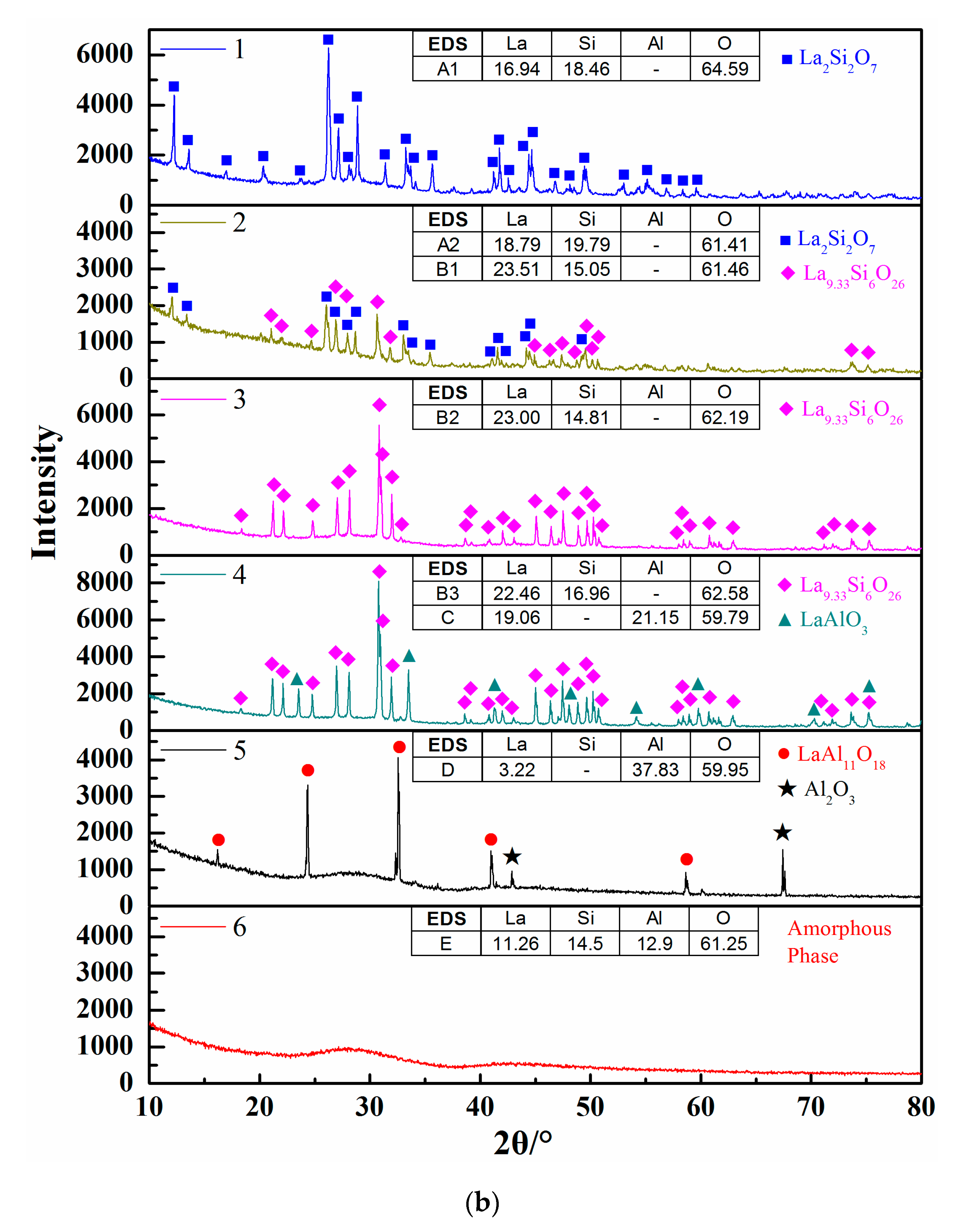
Figure 4b shows the calculated isothermal section diagram at 1500 °C associating with the experimental results in the tube furnace. All the 18 prepared samples were observed and the symbols with the same shape indicate the same precipitated phase. For example, four solid squares located at the top left corner mean the precipitated phase analyzed by EDS and XRD is La2Si2O7. The micromorphology and phase compositions of quenched samples marked with circles in Figure 4b are given in Figure 5, and the elements ratio of EDS results of detecting points in Figure 5a, such as A1, B1, and D, are listed in Figure 5b. The compounds predicted from EDS results and XRD analysis are also given in Figure 5b. For the 18th sample (★ in Figure 4b), the peak of Al2O3 can be detected although the main phase is LaAl11O18. As the magnified image of the 5th picture shown in Figure 5a, some darker precipitates are present on the lighter phase. It was hard to distinguish the Al2O3 phase and LaAl11O18 phase from the EDS analysis because of the limited resolution of FE-SEM. However, both the Al2O3 and LaAl11O18 phases are detected from the XRD analysis.
It can be seen from Figure 4b that the precipitates of experimental results are located in the corresponding primary crystal region of calculated phase diagram. The homogenous liquid phase points all locate within the region of liquidus at 1500 °C except for the rightmost point. It is easily concluded from Figure 5b that the precipitated phase in the La2O3-SiO2 system is not La4Si3O12 but La4.67Si3O13, which is recognized as La9.33Si6O26 in the XRD results.
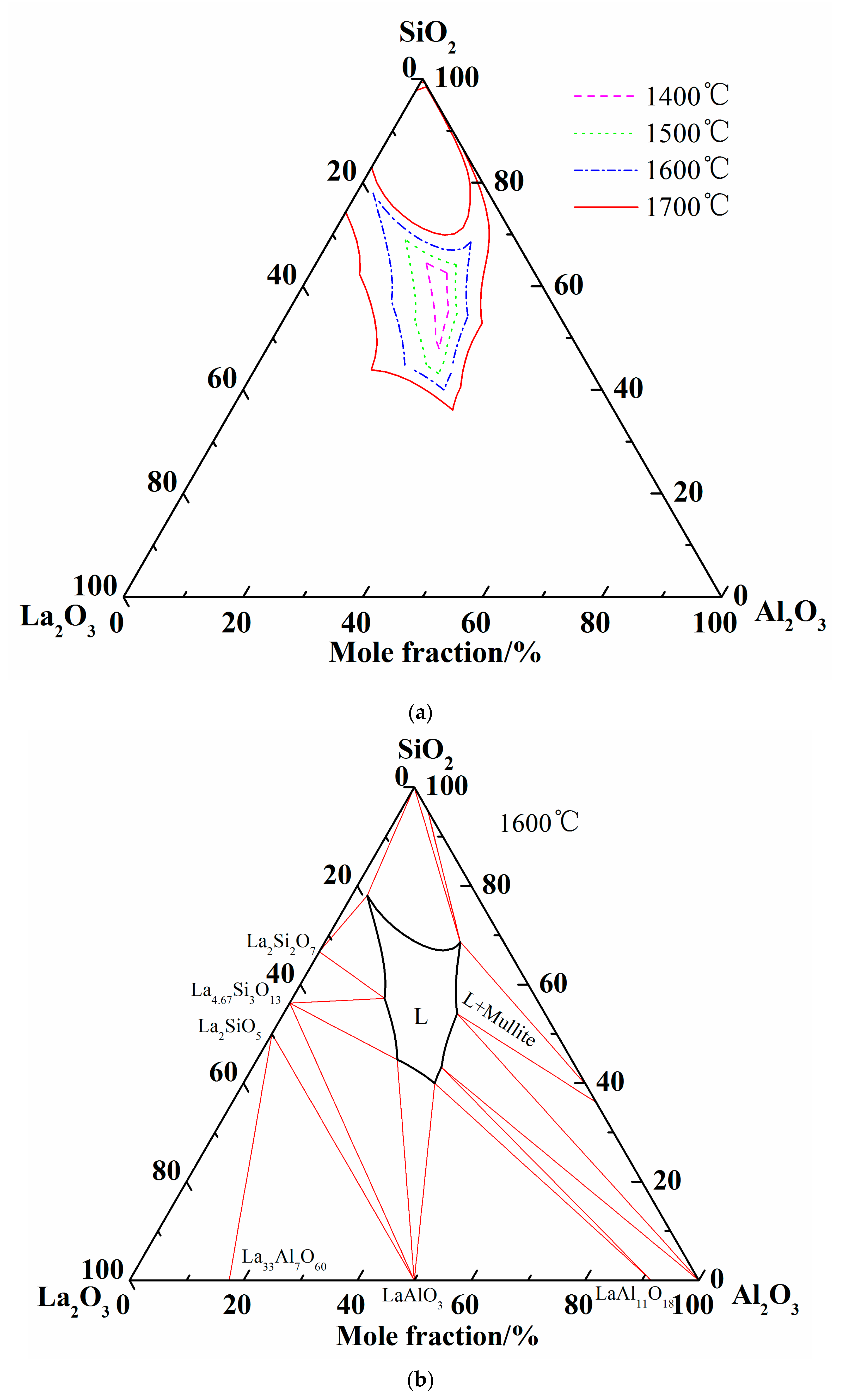
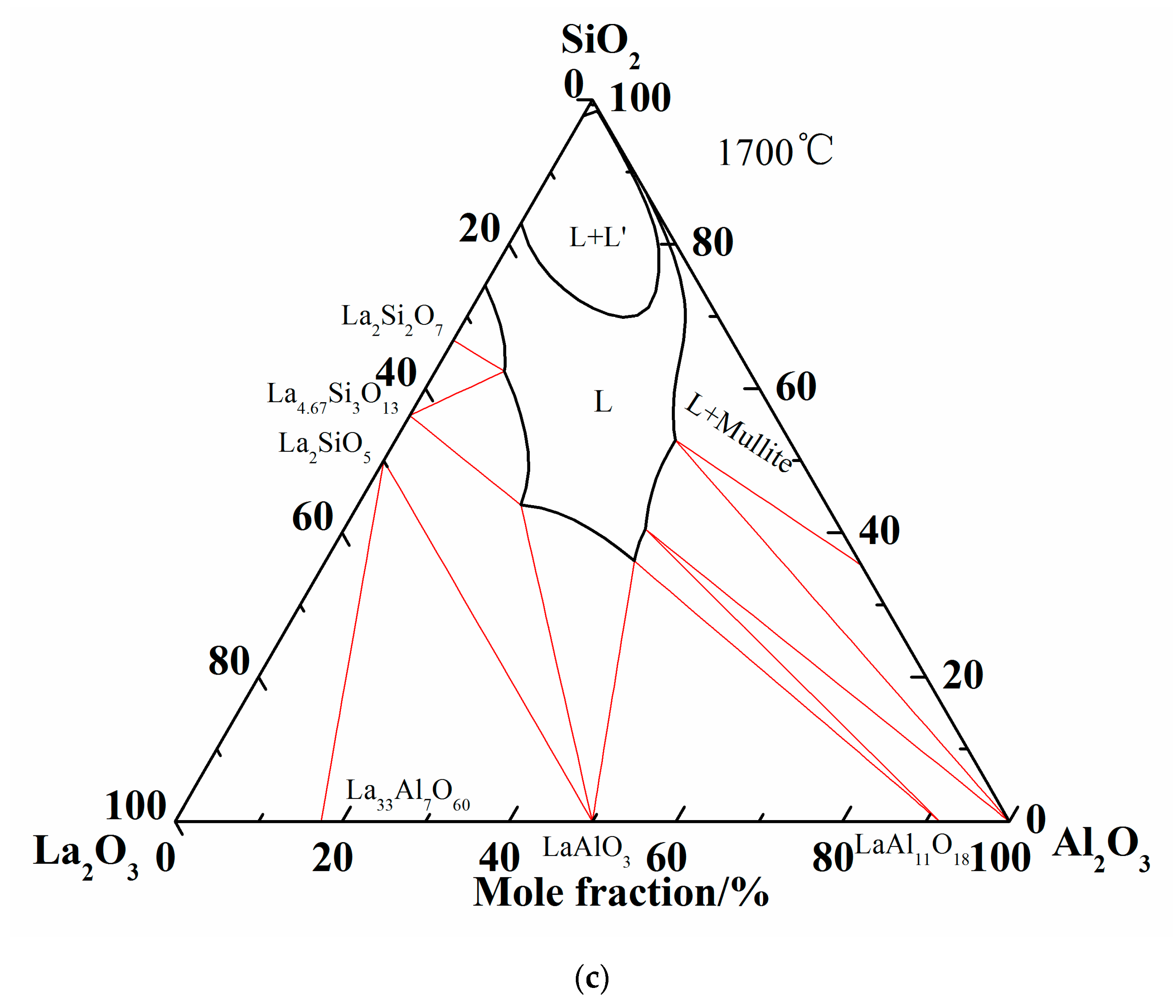
Summing up the above comparison of calculated phase diagram with the experimental results in former literature at 1600 °C and equilibrium experimental results at 1500 °C, it is obvious that the optimized thermodynamic parameters are reliable and the extrapolated Al2O3-SiO2-La2O3 phase diagram is reasonably precise. Therefore, the liquidus and isothermal sections of 1600 °C and 1700 °C are summarized in Figure 6. As shown in Figure 6c, two-liquid region (L + L’) is emerged in the isothermal section diagram of 1700 °C.
4. Summary
La4.67Si3O13 was first introduced to calculate the La2O3-SiO2 system by Redlich–Kister expression, and the Al2O3-SiO2 and La2O3-Al2O3 binary phase diagrams were also optimized by Redlich–Kister expression. The activities of Al2O3 and SiO2 were calculated in the Al2O3-SiO2 binary system, and then the Al2O3-SiO2-La2O3 ternary phase diagram was extrapolated by Kohler method. The conclusions are summarized as follows.
1. The liquid regions at 1500 °C and 1600 °C was verified by both experiments and data from publications. Comparing others’ work, the calculated ternary phase diagram is reliable and presents more precise.
2. It clearly indicated the compound in La2O3-SiO2 system is not La4Si3O12 but La4.67Si3O13.
3. Based on the calculation results in the present study, a more reasonable model should be found to estimate the La2O3-SiO2 system in the future because of the deviation from experimental points. However, the ternary phases diagram in the present work present the relatively reliable region of liquid phase, and it is significant to the glass manufacture and other fields.
Author Contributions
Conceptualization, Y.L. and C.L.; methodology, Y.L.; software, C.L.; validation, Y.F. and T.Z.; formal analysis, Y.L.; investigation, Y.L.; resources, M.J.; data curation, Y.L.; writing—original draft preparation, Y.L.; writing—review and editing, T.Z.; visualization, Y.L.; supervision, C.L.; funding acquisition, Y.L. and M.J. All authors have read and agreed to the published version of the manuscript.
Funding
This research was funded by the National Natural Science Foundation of China (No. 51904035), Natural Science Foundation of Chongqing (cstc2018jcyjAX0792), Open Project from Key Laboratory of Ecological Utilization of Multi-metallic Mineral of Education Ministry (NEMM2018003).
Conflicts of Interest
The authors declare no conflict of interest.
References
- Erbe, E.M.; Day, D.E. Properties of Sm2O3-Al2O3-SiO2 glasses for in vivo applications. J. Am. Ceram. Soc. 1990, 73, 2708–2713. [Google Scholar] [CrossRef]
- Kohli, J.T.; Shelby, J.E. Rare-earth aluminogermanate glasses. J. Am. Ceram. Soc. 1991, 74, 1031–1035. [Google Scholar] [CrossRef]
- Tanabe, S.; Hirao, K.; Soga, N. Elastic properties and molar volume of rare-earth aluminosilicate glasses. J. Am. Ceram. Soc. 1992, 75, 503–506. [Google Scholar] [CrossRef]
- Iftekhar, S.; Pahari, B.; Okhotnikov, K.; Jaworski, A.; Stevensson, B.; Grins, J.; Edén, M. Properties and structures of RE2O3-Al2O3-SiO2 (RE = Y, Lu) glasses probed by molecular dynamics simulations and solid-state NMR: The roles of aluminum and rare-earth ions for dictating the microhardness. J. Phys. Chem. 2012, 116, 18394–18406. [Google Scholar] [CrossRef]
- Mahapatra, M.K.; Lu, K. Seal glass for solid oxide fuel cells. J. Power Sources 2010, 195, 7129–7139. [Google Scholar] [CrossRef]
- Kohli, J.; Shelby, J. Formation and properties of rate earth aluminosilicate glasses. Phy. Chem. Glasses 1991, 32, 67–71. [Google Scholar]
- Kolitsch, U.; Scifert, H.; Aldinger, F. Phase relationships in the systems RE2O3-Al2O3-SiO2 (RE = rare earth element, Y and Sc). J. Phase Equilib. 1998, 19, 426–433. [Google Scholar] [CrossRef]
- Mazza, D.; Ronchetti, S. Study on the Al2O3-SiO2-La2O3 ternary system at 1300 °C. Mater. Res. Bull. 1999, 34, 1375–1382. [Google Scholar] [CrossRef]
- Bondar, I.A.; Galakhov, F.Y. Phase equilibria in the system Y2O3-SiO2-Al2O3. Bull. Acad. Sci. USSR Div. Chem. Sci. 1964, 13, 1231–1232. [Google Scholar] [CrossRef]
- Kolitsch, U.; Seifert, H.; Ludwig, T.; Aldinger, F. Phase equilibria and crystal chemistry in the Y2O3–Al2O3–SiO2 system. J. Mater. Sci. 1999, 14, 447–455. [Google Scholar] [CrossRef]
- Kolitsch, U.; Seifert, H.; Aldinger, F. Phase relationships in the system Gd2O3-Al2O3-SiO2. J. Alloys Compd. 1997, 257, 104–114. [Google Scholar] [CrossRef]
- Kolitsch, U. High Temperature Calorimetry and Phase Analysis in RE2O3-Al2O3-SiO2 Systems. Ph.D. Thesis, University of Stuttgart, Stuttgart, Germany, 1995. [Google Scholar]
- Colomban, P.; Mazerolles, L. SiO2-Al2O3 phase diagram and mullite non-stoichiometry of sol-gel prepared monoliths: Influence on mechanical properties. J. Mat. Sci. Lett. 1990, 9, 1077–1079. [Google Scholar] [CrossRef]
- Pons, A.; Béchade, E.; Jouin, J.; Colas, M.; Geffroy, P.M.; Masson, O.; Slodczyk, A. Structural modifications of lanthanum silicate oxyapatite exposed to high water pressure. J. Eur. Ceram. Soc. 2017, 37, 2149–2158. [Google Scholar] [CrossRef]
- Li, L.; Tang, Z.; Sun, W.; Wang, P. Phase diagram prediction of the Al2O3-SiO2-La2O3 system. J. Mater. Sci. Technol. 1999, 15, 439–443. [Google Scholar]
- Li, L.; Tang, Z.; Sun, W.; Wang, P. Phase diagram estimation of the Al2O3-SiO2-Gd2O3 system. Phys. Chem. Glasses B 1999, 140, 126–129. [Google Scholar]
- Li, L.; Tang, Z.; Sun, W.; Wang, P. Phase diagram estimation of the Al2O3-SiO2-RE2O3 systems. J. Shanghai Univ. 2000, 4, 72–80. [Google Scholar] [CrossRef]
- Iftekhar, S.; Grins, J.; Gunawidjaja, P.N.; Mattias, E. Glass formation and structure-property-composition relations of the RE2O3-Al2O3-SiO2 (RE= La, Y., Lu, Sc) systems. J. Am. Ceram. Soc. 2011, 94, 2429–2435. [Google Scholar] [CrossRef]
- Redlich, O.; Kister, A. Algebraic Representation of thermodynamic properties and the classification of solutions. Ind. Eng. Chem. Res. 1948, 40, 345–348. [Google Scholar] [CrossRef]
- Pelton, A.D. A general “Geometric” thermodynamic model for multicomponent solutions. Calphad 2001, 25, 319–328. [Google Scholar] [CrossRef]
- Barin, I. Thermochemical Data of Pure Substances, 3rd ed.; VCH: Weinheim, Germany, 1995. [Google Scholar]
- Wu, P.; Pelton, A.D. Coupled thermodynamic phase diagram assessment of the rare earth oxide-aluminium oxide binary systems. J. Alloys Compd. 1992, 179, 259–287. [Google Scholar] [CrossRef]
- Chase, M.W. NIST-JANAF thermochemical tables. J. Phys. Chem. Ref. Data 1998, 9, 158. [Google Scholar]
- Knacke, O.; Kubaschewski, O.; Hesselmann, K. Thermochemical Properties of Inorganic Substances; Springer: Berlin, Germany, 1991. [Google Scholar]
- Bolech, M.; Janssen, F.J.J.G.; Booij, A.S.; Cordfunke, E.H.P. The standard molar enthalpies of formation of β-La2Si2O7 and β-Ce2Si2O7. J. Chem. Thermodyn. 1996, 28, 1319–1324. [Google Scholar] [CrossRef]
- Bolech, M.E.; Cordfunke, H.P.; van Genderen, A.C.G.; van der Laan, R.R.; Janssen, F.J.J.G.; van Miltenburg, J.C. The heat capacity and derived thermodynamic functions of La2Si2O7 and Ce2Si2O7 from 4 to 1000 K. Thermochim. Acta 1996, 284, 253–261. [Google Scholar] [CrossRef]
- Li, Y.; Li, C.; Liu, C.; Jiang, M. Thermodynamic assessment of RE2O3-SiO2 (RE = La, Ce) systems. Chin. Rare Earths 2016, 37, 9–13. [Google Scholar]
- DÖrner, P.; Gauckler, L.J.; Krieg, H.; Lukas, H.L.; Petzow, G.; Weiss, J. On the calculation and representation of multicomponent systems. Calphad 1979, 3, 241–257. [Google Scholar] [CrossRef]
- Ball, R.G.A.; Mignanelli, M.A.; Barry, T.I.; Gisby, J.A. The calculation of phase equilibria of oxide core-concrete systems. J. Nucl. Mater. 1993, 201, 238–249. [Google Scholar] [CrossRef]
- Eriksson, G.; Pelton, A.D. Critical evaluation and optimization of the thermodynamic properties and phase diagrams of the CaO-Al2O3, Al2O3-SiO2, and CaO-Al2O3-SiO2 systems. Metall. Mater. Trans. B 1993, 24, 807–816. [Google Scholar] [CrossRef]
- Zaitsev, A.I.; Litvina, A.D.; Mogutnov, B.M.; Tsaplin, A.A. Thermodynamic properties and phase equilibria in the system CaO-SiO2-Al2O3. High Temp. Mater. Sci. 1995, 34, 223–231. [Google Scholar]
- Bowen, N.L.; Greig, J.W. The system: Al2O3. SiO2. J. Am. Ceram. Soc. 1924, 7, 238–254. [Google Scholar] [CrossRef]
- Aramaki, S.; Roy, R. Revised phase diagram for the system Al2O3-SiO2. J. Am. Ceram. Soc. 1962, 45, 229–242. [Google Scholar] [CrossRef]
- Klug, F.J.; Prochazka, S.; Doremus, R.H. Alumina-silica phase diagram in the mullite region. J. Am. Ceram. Soc. 1987, 70, 750–759. [Google Scholar] [CrossRef]
- Davis, R.F.; Pask, J.A. Diffusion and reaction studies in the system Al2O3-SiO2. J. Am. Ceram. Soc. 1972, 55, 525–531. [Google Scholar] [CrossRef]
- Toropov, N.A.; Galakhov, F.I. Solid solutions in the Al2O3-SiO2 system. Izv. Akad. Nauk SSSR Ser. Khim. 1958, 1, 8–11. [Google Scholar] [CrossRef]
- Björkvall, J.; Stolyarova, V.L. A mass spectrometric study of Al2O3-SiO2 melts using a knudsen cell. Rapid Commun. Mass Spectrom. 2001, 15, 836–842. [Google Scholar] [CrossRef] [PubMed]
- Mao, H.; Selleby, M.; Sundman, B. Phase equilibria and thermodynamics in the Al2O3-SiO2 system-modeling of mullite and liquid. J. Am. Ceram. Soc. 2005, 88, 2544–2551. [Google Scholar] [CrossRef]
- MacDowell, J.F.; Beal, G.H. Immiscibility and crystallization in Al2O3-SiO2 glasses. J. Am. Ceram. Soc. 1969, 52, 17–25. [Google Scholar] [CrossRef]
- Bondar, I.A.; Vinogradova, N.V. Phase equilibria in the lanthanum oxide-alumina system. Russ. Chem. Bull. 1964, 13, 737–741. [Google Scholar] [CrossRef]
- Mizuno, M.; Berjoan, R.; Coutures, J.P.; Foex, M. Phase diagram of the system Al2O3-La2O3 at elevated temperature. Yogyo Kyokaishi 1974, 82, 631–636. [Google Scholar]
- Fritsche, E.T.; Tensmeyer, L.G. Liquidus in the alumina-rich system La2O3-Al2O3. J. Am. Ceram. Soc. 1967, 50, 167–168. [Google Scholar] [CrossRef]
- Rolin, M.; Thanh, P.H. Les diagrammes de phases des mélanges ne réagissant pas avec le molybdène. Revue des Hautes Températures et Réfractaires 1965, 2, 175–185. [Google Scholar]
- Kim, S.S.; Park, J.Y.; Sanders, T.H. Thermodynamic modeling of the miscibility gaps and the metastability in the R2O3-SiO2 systems (R= La, Sm, Dy, and Er). J. Alloys Compd. 2001, 321, 84–90. [Google Scholar] [CrossRef]
- Toropov, N.A.; Bondar, I.A.; Galakhov, F.J. High-temperature solid solutions of silicates of the rare earth elements. In Proceedings of the Transaction of the 8th International Ceramic Congress, Copenhagen, Denmark, 14–19 May 1962; pp. 85–103. [Google Scholar]
- Bondar, I.A. Rare-earth silicates. Ceram. Int. 1982, 8, 83–89. [Google Scholar] [CrossRef]
- Tas, A.C.; Akinc, M. Phase relations in the system Al2O3-Ce2Si2O7 in the temperature range 900 °C to 1925 °C in inert atmosphere. J. Am. Ceram. Soc. 1993, 76, 1595–1601. [Google Scholar] [CrossRef]
- Li, Y.; Liu, C.; Zhang, T.; Jiang, M.; Peng, C. Thermodynamic assessment of Al2O3-SiO2-Ce2O3 system. Metall. Res. Technol. 2017, 114, 304. [Google Scholar] [CrossRef]
Figure 1.
Schematic diagram of high temperature furnace.

Figure 2.
Calculated phase diagrams of binary systems. (a) Phase diagram of SiO2-Al2O3 system; (b) Phase diagram of La2O3-Al2O3 system; (c) Phase diagram of La2O3-SiO2 system.
Figure 2.
Calculated phase diagrams of binary systems. (a) Phase diagram of SiO2-Al2O3 system; (b) Phase diagram of La2O3-Al2O3 system; (c) Phase diagram of La2O3-SiO2 system.


Figure 3.
Calculated activity curves in the SiO2-Al2O3 system at 1877 °C. (a) The SiO2 activity in SiO2-Al2O3 system; (b) The Al2O3 activity in SiO2-Al2O3 system.
Figure 3.
Calculated activity curves in the SiO2-Al2O3 system at 1877 °C. (a) The SiO2 activity in SiO2-Al2O3 system; (b) The Al2O3 activity in SiO2-Al2O3 system.

Figure 4.
Comparison of liquid region of ternary phase diagrams. (a) Liquid regions of ternary phase diagrams at 1600 °C; (b) Liquid region and experimental points at 1500 °C.
Figure 4.
Comparison of liquid region of ternary phase diagrams. (a) Liquid regions of ternary phase diagrams at 1600 °C; (b) Liquid region and experimental points at 1500 °C.

Figure 5.
Morphology and component analysis of phases formed at 1500 °C. (a) SEM images of phases formed at 1500 °C; (b) XRD patterns of phases formed at 1500 °C, 1–6 represent the XRD patterns of experimental points 1-6 marked in Figure 4b, respectively.
Figure 5.
Morphology and component analysis of phases formed at 1500 °C. (a) SEM images of phases formed at 1500 °C; (b) XRD patterns of phases formed at 1500 °C, 1–6 represent the XRD patterns of experimental points 1-6 marked in Figure 4b, respectively.


Figure 6.
More calculations of Al2O3-SiO2-La2O3 ternary phase diagram. (a) Isothermal curves of Al2O3-SiO2-La2O3 system; (b) Isothermal section of Al2O3-SiO2-La2O3 system at 1600 °C; (c) Isothermal section of Al2O3-SiO2-La2O3 system at 1700 °C.
Figure 6.
More calculations of Al2O3-SiO2-La2O3 ternary phase diagram. (a) Isothermal curves of Al2O3-SiO2-La2O3 system; (b) Isothermal section of Al2O3-SiO2-La2O3 system at 1600 °C; (c) Isothermal section of Al2O3-SiO2-La2O3 system at 1700 °C.


Table 1.
Thermodynamic properties of pure substances.
| Formula | Phase | Cp = A + B·10−3 T + C·105 T−2 + D·10−6 T2 (J·mol−1·K−1) | Applicable Temperature | |||||
|---|---|---|---|---|---|---|---|---|
| A | B | C | D | (K) | ||||
| La2O3 | S [21] | −1793.702 | 127.319 | 119.733 | 14.225 | −13.506 | - | 298–2553 |
| L [22] | −1728.858 | 152.423 | 119.729 | 14.230 | −13.500 | - | 2553–3000 | |
| Al2O3 | S [21] | −1675.692 | 50.936 | 109.909 | 22.065 | −33.284 | −4.085 | 298–2327 |
| L [23] | −1596.533 | 43.569 | 192.464 | - | - | - | 2327–3000 | |
| SiO2 | S [21] | −910.857 | 41.463 | 72.923 | 1.148 | −41.848 | 0.036 | 298–1996 |
| L [21] | −906.604 | 51.029 | 85.772 | - | - | - | 1996–3000 | |
| LaAlO3 | S [24] | −1794.300 | 85.936 | 111.010 | 13.481 | −21.129 | - | 800–1500 |
| LaAl11O18 | S [22] | −10,107.591 | 383.296 | 697.843 | 103.054 | −258.334 | −19.660 | 298–2201 |
| La33Al7O60 | S [22] | −35,652.907 | 2404.150 | 2381.521 | 295.843 | −382.856 | −12.510 | 298–2161 |
| La2Si2O7 | S [25,26] | −3815.699 | 210.271 | 220.760 | 72.124 | −41.832 | −0.029 | 298–1000 |
| La2SiO5 | S * | −2853.310 | 168.782 | 182.9117 | 27.278 | −33.6 | - | 298–3000 |
| La4.67Si3O13 | S * | −7302.500 | 421.467 | 463.165 | 73.192 | −86.8 | - | 298–3000 |
* Derived from thermodynamic properties of La2O3 and SiO2 [27].
Table 2.
Optimization parameters of the binary systems.
| Li = a + bT | - | L0 | L1 | L2 | L3 |
|---|---|---|---|---|---|
| Al2O3-SiO2 | a | 19,570.28 | 14,875.48 | 5640.02 | - |
| b | −10.49 | −0.71 | 1.21 | - | |
| La2O3-Al2O3 | a | −129,195.34 | −15,094.54 | 393,830.17 | - |
| b | −26.05 | 0.72 | −176.58 | - | |
| La2O3-SiO2 | a | −352,587.83 | −119,125.74 | 513,748.94 | 435,926.54 |
| b | 78.86 | 22.64 | −211.27 | −166.77 |
© 2020 by the authors. Licensee MDPI, Basel, Switzerland. This article is an open access article distributed under the terms and conditions of the Creative Commons Attribution (CC BY) license (http://creativecommons.org/licenses/by/4.0/).
Share and Cite
MDPI and ACS Style
Li, Y.; Zhang, T.; Feng, Y.; Liu, C.; Jiang, M. Liquid Regions of Lanthanum-Bearing Aluminosilicates. Materials 2020, 13, 450. https://0-doi-org.brum.beds.ac.uk/10.3390/ma13020450
AMA Style
Li Y, Zhang T, Feng Y, Liu C, Jiang M. Liquid Regions of Lanthanum-Bearing Aluminosilicates. Materials. 2020; 13(2):450. https://0-doi-org.brum.beds.ac.uk/10.3390/ma13020450
Chicago/Turabian StyleLi, Yandong, Tongsheng Zhang, Yefeng Feng, Chengjun Liu, and Maofa Jiang. 2020. "Liquid Regions of Lanthanum-Bearing Aluminosilicates" Materials 13, no. 2: 450. https://0-doi-org.brum.beds.ac.uk/10.3390/ma13020450
Note that from the first issue of 2016, this journal uses article numbers instead of page numbers. See further details here.