Article

Microstructure Evolution and Mechanical Properties of a Wire-Arc Additive Manufactured Austenitic Stainless Steel: Effect of Processing Parameter

1
State Key Laboratory of Materials Processing and Die & Mould Technology, School of Materials Science and Engineering, Huazhong University of Science and Technology, Wuhan 430074, China
2
College of Mechanical Engineering, Dongguan University of Technology, Dongguan 523808, China
*
Author to whom correspondence should be addressed.
These authors contributed equally to this work.
Submission received: 1 March 2021 / Revised: 18 March 2021 / Accepted: 23 March 2021 / Published: 29 March 2021

Abstract

:
Two single track multi-layer walls with linear energy inputs (LEIs) of 219 and 590 J/mm were deposited by cold metal transfer-based wire arc additive manufacturing system. Combined with the X-ray diffraction technique, scanning electron microscope and uniaxial tensile tests, the influences of LEI and cooling rate (CR) on the microstructure evolution, mechanical properties and fracture mechanisms of the studied steel are analyzed. It is observed that the microstructures of the studied steel are mainly composed of δ-ferrite and austenite dendrites. σ phase is formed on the δferrite–austenite interface under low CR. Meanwhile, the primary dendrites’ spacing decreases with the decrease in LEI or the increase in CR, and the maximal primary dendrites’ spacing is 32 μm. The values of elongation to fracture roughly decline with the decrease in LEI or the increase in CR, but the variations of ultimate tensile strength and yield stress show an opposite trend. In addition, the mesoscopic damages in the studied steel under low LEI are mainly caused by the coalescence of pores. While under high LEI, the cracks are induced by the dislocations piling up around δ-ferrite.

1. Introduction

Generally, the complex components are hardly integrally manufactured by traditional forming processes (such as casting and forging) and need to be divided into several subcomponents [1,2]. Due to the high design freedom and material utilization, additive manufacturing (AM) technologies are widely applied to fabricate or repair the complex metallic components by the local delivery of metal wire or powder [3,4,5]. According to the heat sources, the AM technologies are classified into wire arc additive manufacturing (WAAM) [6,7], laser powder-based fusion (LPBF) [8,9], and electron beam melting (EBM) [10,11]. LPBF and EBM are commonly used to form components with high dimensional accuracy [12]. However, the applications of EBM and LPBF need to be kept in enclosed environments [13]. Therefore, the component sizes are greatly influenced by the spacing of the enclosed working chamber.
Recently, larger components were expected to be fabricated through additive manufacturing technologies [14,15]. Due to the low equipment cost and high deposition rate, great attention has been paid to WAAM technology [16]. The traditional commercial welding power source can be directly applied in the WAAM process. Moreover, the WAAM enjoys a potentially unlimited component size in open working environments [17,18]. However, there are still some disadvantages for the application of WAAM. During WAAM, the processing parameters, including wire feed speed, scanning speed and shielding gas flow, significantly affect the size, thermodynamic and dynamic properties of the molten pool [19,20]. For the large temperature gradient and cycling reheating, the preferred layer sizes, fine microstructures as well as homogeneous elements distributions are hardly obtained [21,22]. After cooling, the microstructures of the components are constituted by plenty of columnar dendrites [23]. The inhomogeneous microstructure and anisotropy effect would further influence the mechanical properties of additive manufactured components [24]. The relatively poor dimensional accuracy is another unfavorable impact for the wide application of WAAM [25,26]. For overcoming the above shortcomings, many researches focusing on dimensional and microstructure control of components were conducted for the WAAM process [27,28,29]. Dai et al. [30] studied the slicing and scanning strategies of the WAAM process for manufacturing a multi-directional pipe joint, and successfully controlled the dimensional errors within ±1 mm. Yang et al. [31] analyzed the influences of inter-layer cooling time on the forming appearance of parts by an infrared camera. Xiong et al. [32] investigated the influences of processing parameters on the surface quality of additive manufactured layers and developed a passive vision sensor system to control the layer height. Sun et al. [33] discussed the mechanical properties and microstructure evolution of Inconel 625 superalloy component deposited by WAAM. Considering the multiple thermal cycle effects, Lin et al. [34] employed two WAAM methods (pulsed and continuous plasma arc additive manufacturing) to fabricate Ti-6Al-4V alloy components and revealed the relationship between mechanical properties and microstructures. Guo et al. [35] addressed the effects of pulse frequency on microstructures and the tensile properties of AZ31 magnesium alloy. Additionally, some studies were concerned with the surface morphology, mechanical properties and microstructure of metals, including aluminum alloys [36,37], nickel-based alloys [38,39], titanium alloys [40,41], steels [42,43], as well as intermetallic compounds [44,45] manufactured by WAAM.
Due to the excellent machinability, weldability, mechanical properties and high corrosion resistance, the austenitic stainless steel is widely applied as the structural material used in corrosive environments [46,47,48], such as pipelines, containers and heat exchangers in nuclear, biomedicine and petrochemical fields. With the development of industrial equipment, the size, precision and complexity of parts increases. Compared with traditional casting and forging, WAAM technology is a simple forming process with high production efficiency and material utilization rate [49]. In addition, with the development of WAAM technology, the mechanical properties of 316L WAAM-formed parts are higher than casting parts, and sometimes even reach the level of forging parts [50].
During the AM process, the high cooling rate aggravates the inhomogeneous elements distribution. δ-ferrite cannot totally transform into austenite in a short cooling period [4]. The microstructures of AM-fabricated components mainly consist of residual δ-ferrite and austenite [51]. Yadollahi et al. [52] clarified the influences of inter-layer time and thermal history on the mechanical properties and microstructures of austenitic stainless steel. Guo et al. [53] investigated the anisotropy of the direct laser deposition (DLD)-processed 316L stainless steel. Ziętala et al. [54] paid attention to the corrosion resistance properties of 316L stainless steel. In order to improve the corrosion resistance and mechanical properties of 316L stainless steel, Chen et al. [55] optimized the heat treatment process to obtain the optimal volume fraction of σ phase and δ-ferrite. Yan et al. [56] investigated the creep–fatigue properties of 316L stainless steel and established a model to predict the life span of studied steel. Miranda et al. [57] established models to clarify the relationship between the processing parameters and mechanical properties of selective laser-melted 316L stainless steel. Xu et al. [58] discussed the influences of annealing treatment on the microstructures of 316LN stainless steel in the temperature range of 600–1000 °C. Wu et al. [59] observed the microstructural evolution of 316LN stainless steel in situ under various cooling rates by a confocal scanning laser microscope. Xiao et al. [60] optimized the arc welding heat input to obtain the preferred cryogenic toughness of 316LN stainless steel. Dai et al. [61] revealed the effects of heat treatment on low-temperature toughness and the microstructure evolution of an austenitic stainless steel.
There are many processing parameters in the WAAM process. Essentially, most parameters, such as scanning speed and wire feeding speed, affect the material properties by changing the energy input and cooling rate of the molten pool. This article directly considers the influence of energy input and cooling rate on the material performance, so that it can help one to understand the microstructure evolution and phase transition mechanism in the WAAM process. In this article, multi-layer 316L stainless steel parts were fabricated by the cold metal transfer (CMT)-based WAAM system, and the effects of the linear energy input (LEI) and cooling rate (CR) on the microstructure evolution, mechanical properties and fracture mechanisms of the studied steel were analyzed in detail.

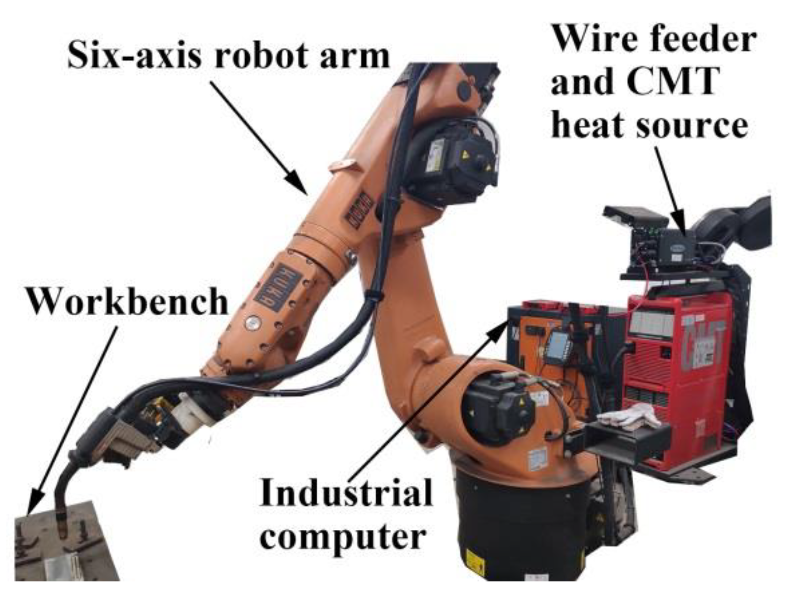
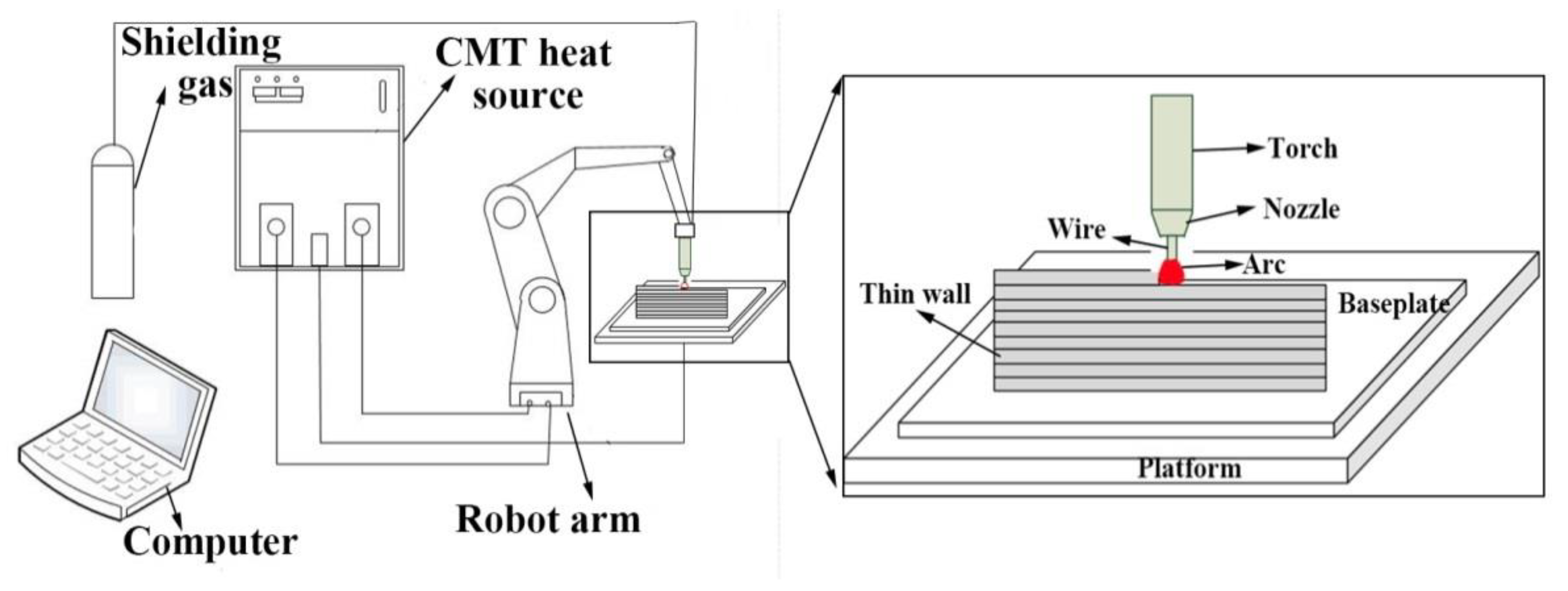
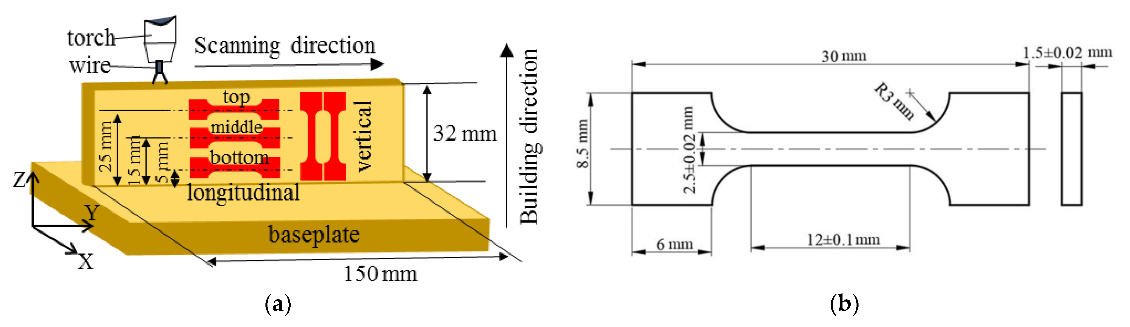
2. Materials and Experiments

The ER316L stainless steel wire with a diameter of 1.2 mm used in this investigation was provided by the TIAUVD company. The chemical compositions are shown in Table 1. The forged 316LN stainless steel baseplate with a size of 200 × 100 × 30 mm3 was grinded and washed in alcohol solution prior to the WAAM process. Two single track multi-layer parts were fabricated by the cold metal transfer (CMT)-based WAAM system, which is shown in Figure 1. Figure 2 shows the schematic of the CMT-based WAAM system. The system is composed of four parts, namely shielding gas, a CMT heat source (CMT 4000 advanced), a robot arm (KUKA KR30-3HA) and an industry personal computer. The gas metal arc was struck between the wire electrode and thin wall. The CMT program during the WAAM process is CMT. As the welding torch moved, wire was melted, and the part was deposited layer by layer. The height of the AM part is 32 mm, and the length is 150 mm. During experiment, the scanning direction of the adjacent layers was reversed. The time interval between two layers was set to 3 min. The flow rate of the protecting gas (80% Ar + 20% CO2) was 25 L/min, and the inner diameter of the gas nozzle was 15 mm. Table 2 shows the processing parameters of WAAM used in this study. The low and high LEI groups represent that the studied steel deposited under the LEI of 219 and 590 J mm−1, respectively.
Generally, different regions of the AM parts undergo different CRs during the WAAM process. In the bottom region of the part, a great deal of heat input is quickly absorbed by the baseplate, and the CR is fast. With the distance away from the baseplate increasing, the effects of heat accumulation and thermal cycle are apparent. Thus, the CR decreases with the increased distance away from the baseplate. In this study, the longitudinal tensile samples were cut from different regions of the AM parts along the scanning direction. The distances from the baseplate to the center line of the bottom, middle and top samples were measured as 5, 15 and 25 mm, respectively. To further investigate the anisotropic effects of the AM parts, the vertical tensile samples were cut along the building direction. The detailed sample position within the AM part and the dimension of sample are shown in Figure 3. Three longitudinal and six vertical tensile samples were made per parameter. Uniaxial tensile tests were carried out on a mechanical testing machine (AG-IC 100kN, Shimadzu Co., Kyoto, Japan) at a strain rate of 2 × 10⁻³ s−1. After fracture, both the transverse and longitudinal sections of samples were observed by SEM (Sirion200, FEI Co., Eindhoven, The Netherlands).
The optical microscope (OM) was adopted to characterize microstructures. The chemical etchant was a mixture solution consisting of 5 mL of HNO3 and 15 mL of HCl. The etching time was around 15 s. X-ray diffraction (XRD) tests (D8 Advance, Broker Co., Karlsruhe, Germany) were conducted with a scan rate of 0.02°/s from 30° to 100°.

3. Results and Discussion

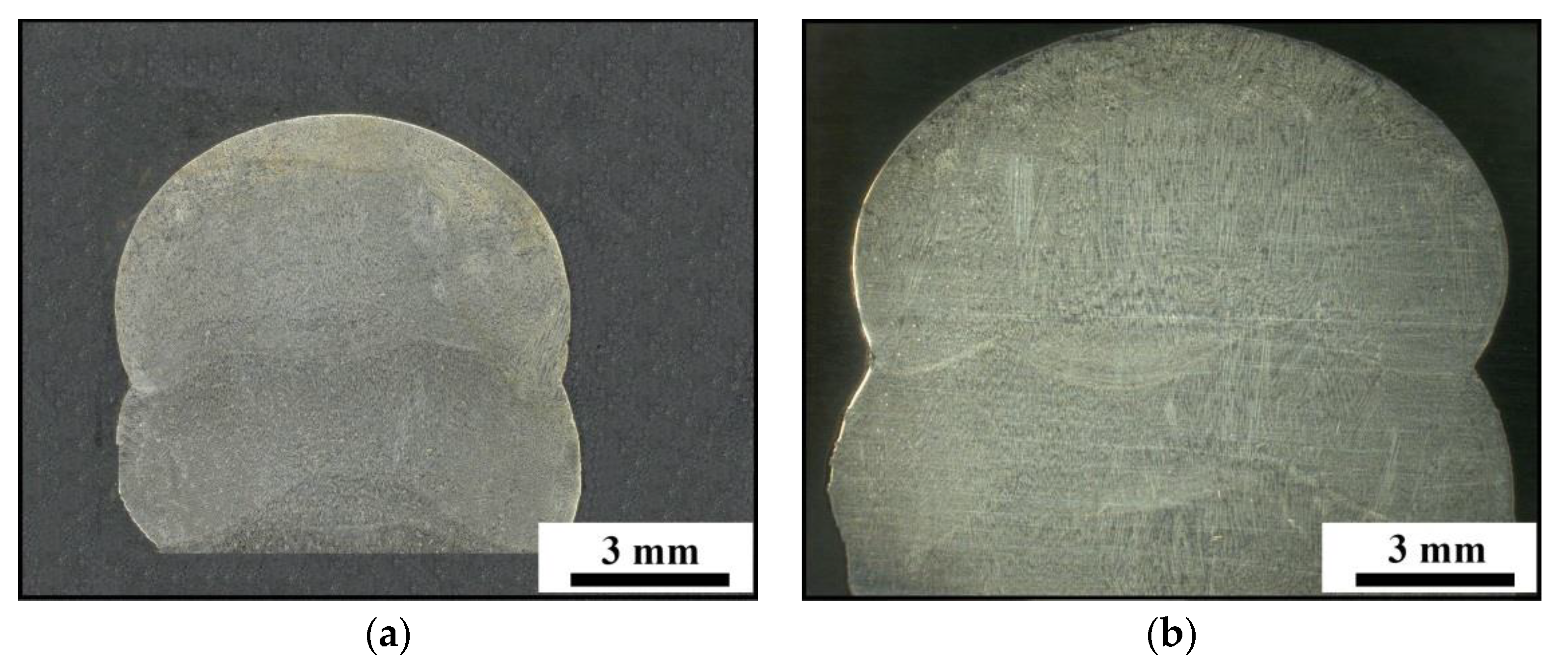
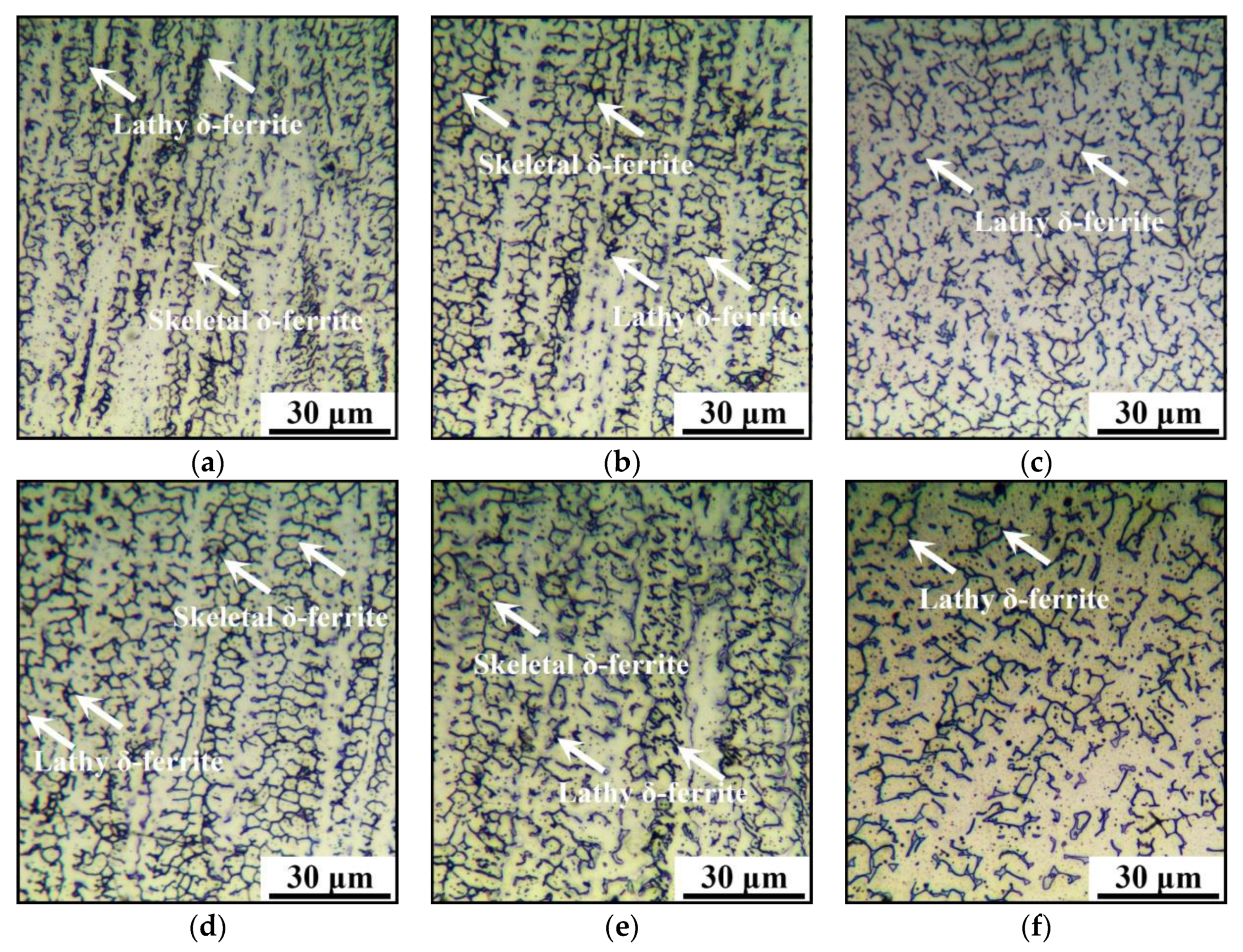
3.1. Microstructure Evolution

As mentioned above, different regions of the AM parts undergo different CRs during the WAAM process. Due to heat accumulation, the CR declines with the increased layers. Figure 4 illustrates the XRD patterns of the AM parts under different LEIs and CRs. It is clear that the diffraction peaks at 41°, 50°, 74°and 90° are well matched with austenite (JCPDS card No. 31-0619). The peaks at 42°, 62° and 81° demonstrate the existence of δ-ferrite. Therefore, the AM parts under different LEIs and low/medium CRs is comprised by δ-ferrite and austenite. The high diffraction peaks of {200} and {220} plane of austenite demonstrates that <100> and <110> are the two favorable growth orientations of the dendrites. However, the diffraction peak of (45°) σ phase (CrFe) is only available in the AM part under high CR. This manifests that σ phase only precipitate under low CR during WAAM. Generally, σ phase precipitate at the ferrite–austenite interface once the temperature stays in the range of 600–900 °C [62,63]. On the other hand, σ phase would dissolve in the austenite matrix when the temperature is above 1050 °C [64]. For the studied steel under high CR, the duration of temperature within 600–900 °C is short. The time is insufficient for the formation of σ phase. With the increase in distance from the baseplate, the effect of heat accumulation is obvious, and the CR decreases. Therefore, enough time is provided for the precipitation of σ phase in the studied steel under medium and high CRs. However, due to the thermal cycle caused by successive layer deposition, the duration of temperature above 1050 °C is long enough for the resolution of σ phase. Therefore, only austenite and δ-ferrite can be found in the AM parts under a medium CR. In the top regions of the AM parts, the duration of temperature exceeding 1050 °C is short, owing to the effect of heat transfer with air. Thus, the σ phase finally survives when CR is low.
Figure 5 shows the macro-morphologies of the top region within the AM parts. The layer widths are 8.2 ± 0.7 mm and 11.4 ± 1.2 mm for the AM parts under low and high LEIs, respectively. A relatively large layer width indicates a small temperature gradient under high LEI. Moreover, a host of columnar dendrites grow along the building direction, as shown in Figure 5b.
The microstructures of the AM parts under different LEIs and CRs are shown in Figure 6. The lathy and skeletal δ-ferrite are observed in the AM parts under medium and high CRs, but only lathy δ-ferrite is available under low CRs. Generally, with the decrease in temperature, the phase transformation follows [65]:
L L + δ - ferrite L + δ - ferrite + austenite δ - ferrite + austenite austenite
where L denotes liquid phase.
During WAAM, owing to the fast CR, the solid phase transformation from δ-ferrite to austenite is non-equilibrium and incomplete, and the skeletal or lathy δ-ferrite survives. Table 3 shows the values of the residual δ-ferrite contents and primary dendrites’ spacing. The contents of residual δ-ferrite under different WAAM processing parameters are evaluated by ImageJ software. For each condition, 10 different metallographic images are selected, and the average values of residual δ-ferrite are obtained. Under low LEI, the spacing of primary dendrites is evaluated as 27, 21 and 18 μm for the AM part with low, medium and high CRs, respectively. With LEI increasing, the spacing of primary dendrites raise to 32, 27 and 23 μm at the low, medium and high CRs, respectively. It is obvious that the primary dendrites’ spacing increases with the decrease in CR. However, the δ-ferrite contents follow an opposite tendency. When LEI is low, the contents of δ-ferrite are 14.5%, 16.2% and 17.3% with the cooling rate decreasing. Under high LEI, the δ-ferrite contents range from 13.2% to 17.7%. In the vicinity of the baseplate, the deposited heat quickly dissipates through conduction. The grain growth is not apparent. With the progress of WAAM, the average temperature of the AM parts increases and the CR decreases. Thus, there is enough time for the columnar dendrites’ growth, which further results in the primary dendrites’ spacing increasing. Meanwhile, numerous δ-ferrite dissolves into the austenite matrix. In consequence, the variation trend of the δ-ferrite content is opposite to that of the primary dendrites’ spacing for the studied steel with different CRs.
Generally, the primary dendrites’ spacing is greatly affected by the nucleation rate and the holding time suitable for grain growth. The nucleation rate mainly depends on the undercooling degree at the solid–liquid interface during solidification. A great undercooling degree accelerates the nucleation of the columnar dendrites. The interface undercooling degree is calculated by the following formulas [66]:
V s = V cos θ
Δ T k = V s γ
where V s is the moving speed of solid–liquid interface, V is the welding speed, θ is the angle between V and V s . Δ T k is the undercooling degree of the interface front, and γ   is the material constant related to the adopted material and local acoustic speed.
According to Equation (2), Δ T k   depends on the moving speed of the interface and is correlated to the welding speed in this study. A fast welding speed leads to a large undercooling degree. The welding speed of the AM part under low LEI is relatively small. Thus, the undercooling degree is large, and the nucleation rate is high.
During WAAM, the grain growth model is expressed by [67]:
g 2 = K 1 τ exp ( Q R T p ) + g 0 2
τ = q 2 π λ e ( T p T 0 )
where   g 0 and g are the initial and ultimate grain size, respectively. Q denotes the thermal activation energy, R is the molar gas constant, and k 1 is material constant. T 0 and T p are the preheating and peak temperature, respectively. λ   is the thermal conductivity, τ is the time suitable for grain growth, and q is the linear energy input.
In this model, the initial grain size is assumed as a constant. The time suitable for grain growth is mainly determined by q and the difference between T 0 and T p . The peak temperature T p approximately reaches the melting temperature of materials during WAAM. Due to the effect of heat accumulation, T 0   gradually increases with the increase in additive layers. Therefore, the time suitable for grain growth gradually increases with the increased layers. On the other hand, the differences between the preheating temperature T 0 and the peak temperature T p are not apparent in the same regions of the AM part. Thus, a suitable   τ for grain growth is mainly related to LEI and increases with the LEI increasing. In conclusion, the primary dendrites’ spacing of the studied steel increases with the increase in LEI or the decrease in CR.

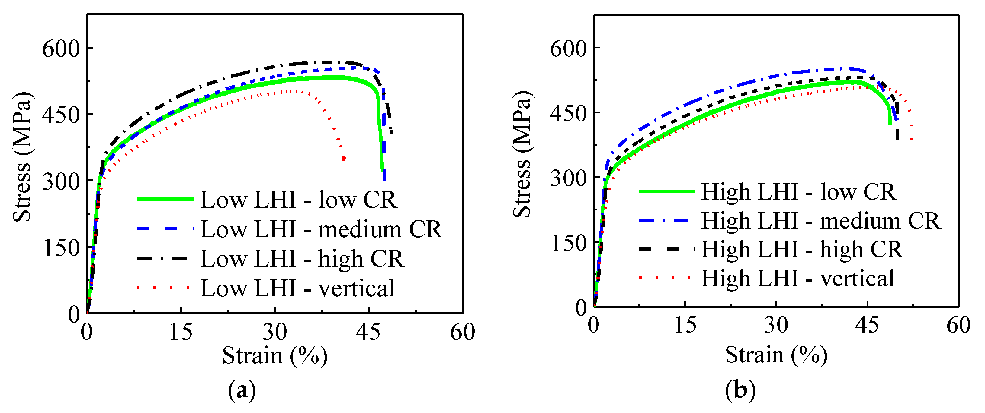
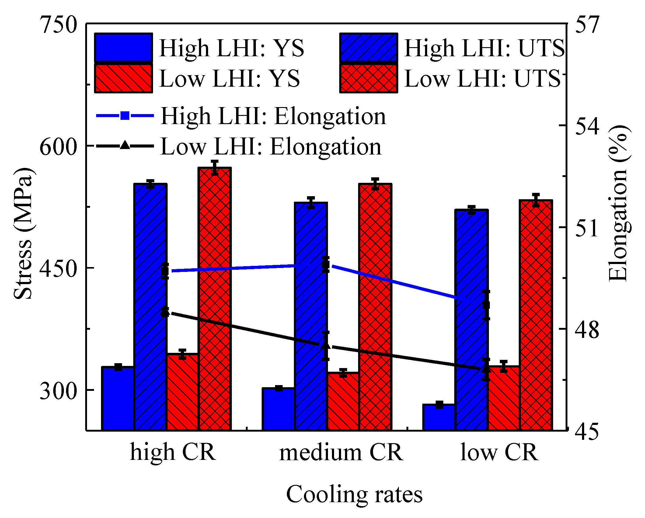
3.2. Mechanical Properties

Figure 7 depicts the engineering stress–strain relationships of the studied steel. Obviously, the mechanical properties are significantly affected by LEI and CR. In detail, Figure 8 shows the yield strength (YS), ultimate tensile strength (UTS) and elongation to fracture of the studied steel under different LEIs and CRs, and the detailed values are listed in Table 4. Under a low LEI, the UTSes are 533, 553 and 573 MPa for the studied steel with low, medium and high CRs, respectively. With the increase in LEI, the UTSes decrease to 521, 530 and 553 MPa for the studied steel under low, medium and high CRs, respectively. The UTS and YS both show an increasing trend with the increase in CR or the decrease in LEI. As mentioned in Section 3.1, the columnar dendrites are gradually refined with the decrease in LEI or the increase in CR. The decrease in the primary dendrite spacing provides numerous grain boundaries, which considerably hinders the movement of dislocations. Therefore, the YS and UTS are preferred for the AM parts under low LEI or high CR.
From Figure 7, it is found that the UTSes and YSes of the vertical tensile samples are relatively low compared with the longitudinal samples under different LEIs. This is mainly resulted from two aspects. Firstly, the columnar dendrites grow along the building direction, which brings about a significant decrease in grain boundaries in the vertical direction. Thus, the grain boundary strengthening effect is diminished, compared with that in the longitudinal direction. On the other hand, the inter-layer interface is likely to induce some defects such as pores, which further weakens the tensile properties. Therefore, the longitudinal tensile samples have preferred UTSes and YSes compared with vertical samples. Additionally, the elongation to fracture relatively follows an increased trend with the increase in LEI or CR, as shown in Figure 8.

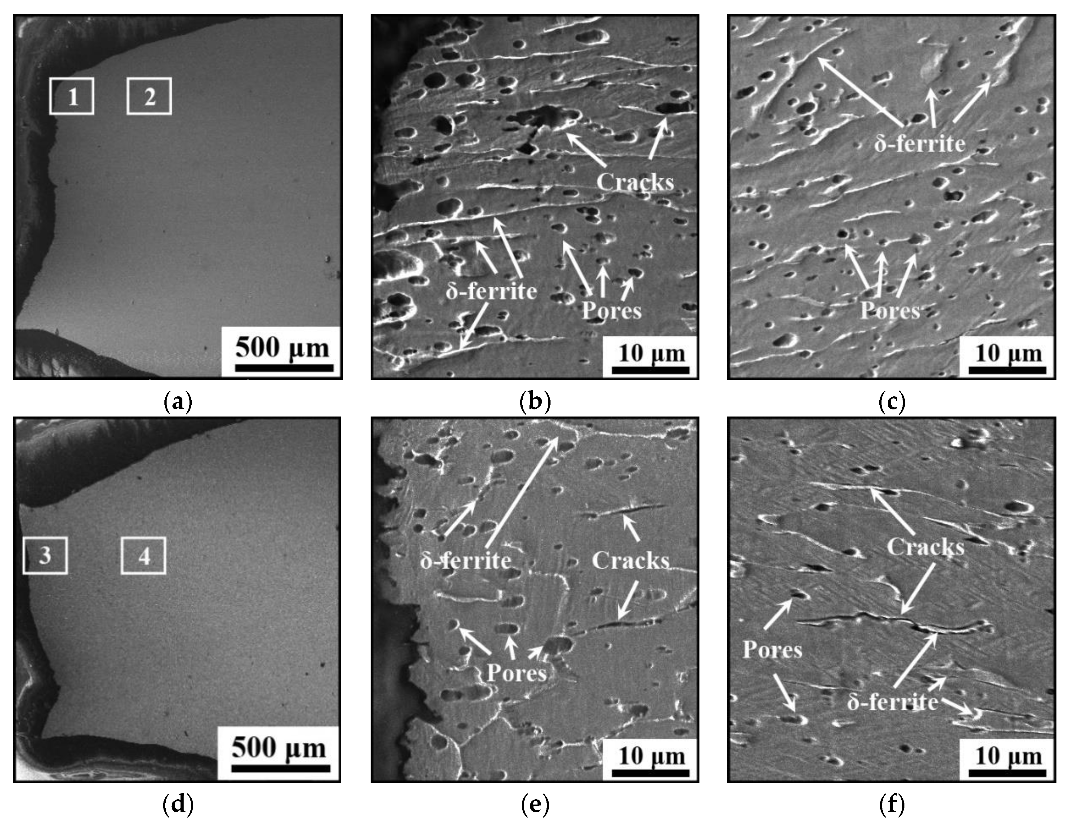
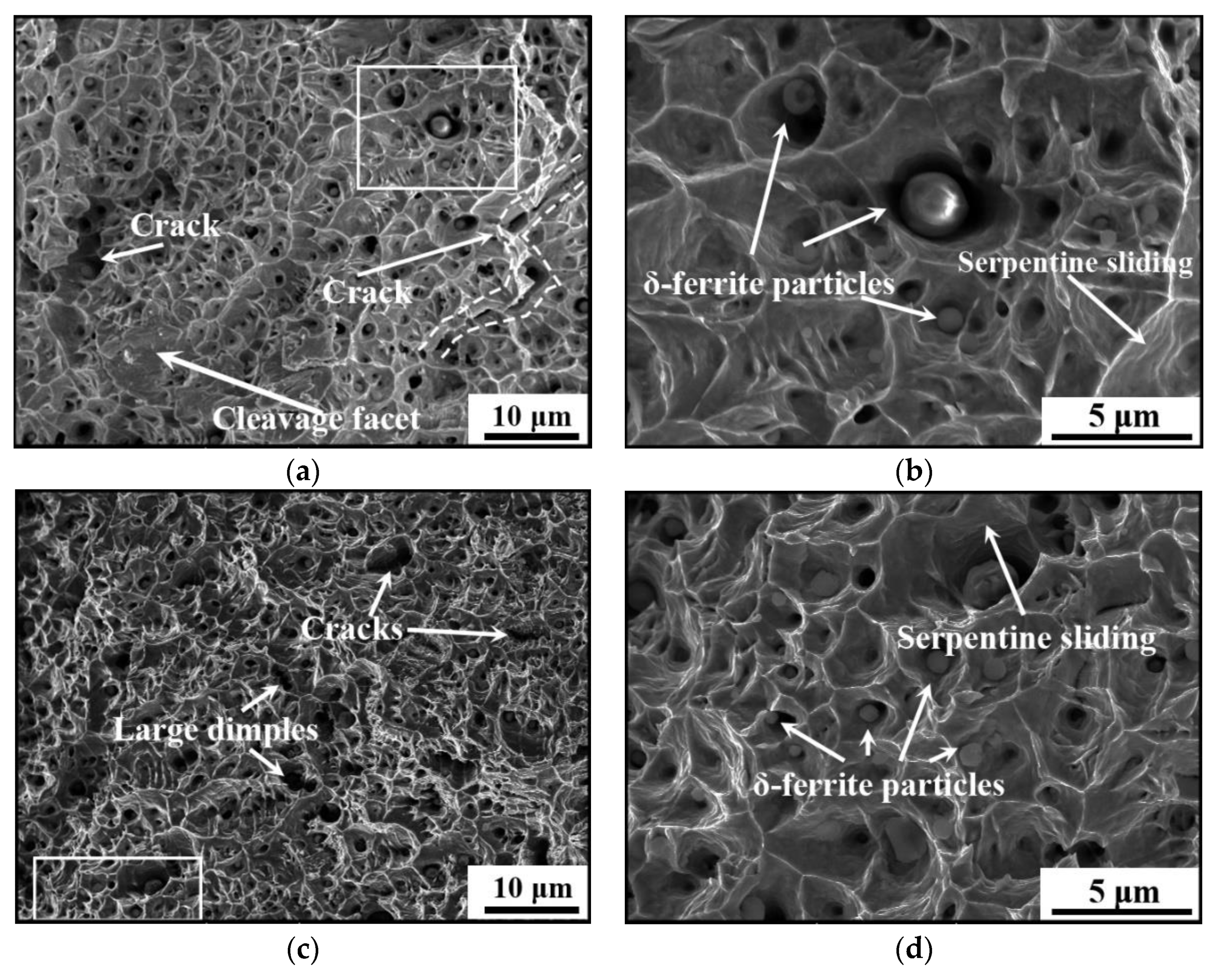
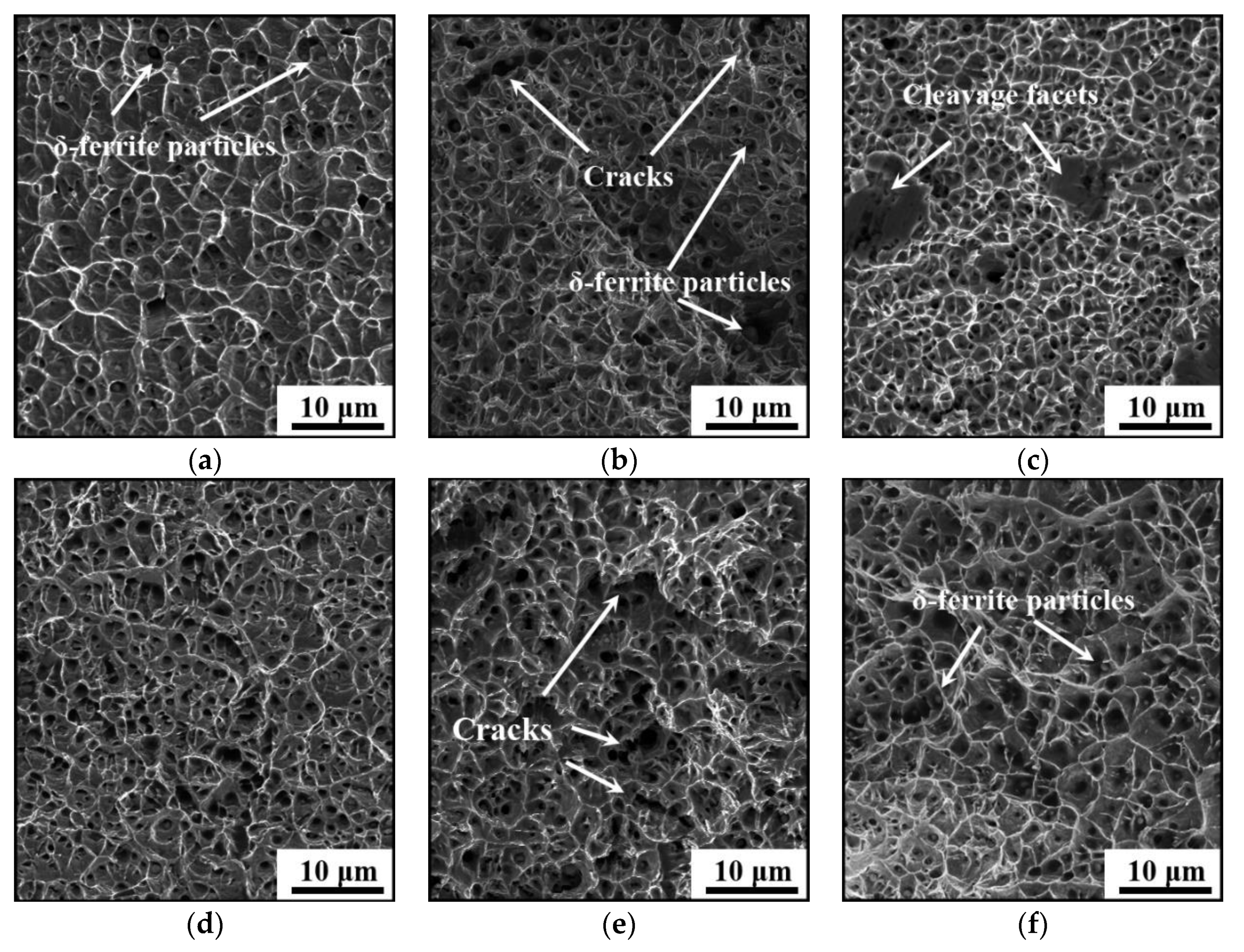
3.3. Fracture Morphologies

Figure 9 shows the longitudinal sectional morphologies of the vertical tensile samples under different LEIs. The sectional shrinkage rates are evaluated as 48.8% and 54.1% for the studied steel under low and high LEIs, respectively. Generally, a large sectional shrinkage rate indicates the material with an excellent plasticity. Figure 9b,c,e,f are the magnified graphs of regions marked as 1, 2, 3 and 4 in Figure 9a,d, respectively. Obviously, δ-ferrite is thick in the studied steel under low LEI, and is elongated along the tensile direction during the progress of tension, as shown in Figure 9b,c. Moreover, pores and cracks are observed, and the number of pores is relatively large under low LEI. During the solidification of the additive layer, the fast cooling rate prevents the escape of gas from the liquid metal, and numerous pores are formed. It also can be found from Figure 9b that the cracks are mainly caused by the coalescence of pores for the studied steel under low LEI. With the increase in LEI, a small number of pores exist on the longitudinal sectional morphologies of the tensile samples, as shown in Figure 9e. The coalescence of pores is not apparent with the progress of the tension. Meanwhile, several cracks occur along the tensile direction, as shown in Figure 9f. This is mainly attributed to hindering the movement of dislocations by δ-ferrite during the tensile deformation. A great number of dislocations pile up around δ-ferrite, resulting in the stress concentration. Once the critical bonding stress of the interface is exceeded, cracks occur. Therefore, the fracture of the studied steel under high LEI results from the disbanding between δ-ferrite and austenite matrix.
Figure 10 shows the fracture surfaces of the vertical tensile samples under different LEIs. The fracture morphologies are covered with numerous equiaxed dimples and tearing edges. This indicates that the formation and coalescence of micro-voids lead to the final fracture of the studied steel. Besides, large dimples and micro-cracks are formed by the coalescence of dimples, which severely deteriorates the plasticity of the studied steel. From Figure 10a, it is found that numerous dimples distribute on the fracture surfaces for the studied steel under low LEI. Several cleavage facets caused by the coalescence of pores also exist on the fracture surfaces. It is found from Figure 10c that the dimples of the studied steel under high LEI are relatively deep compared to that in Figure 10a. In general, deep dimples mean that the dimples have experienced large deformation before the final fracture. Therefore, the studied steel under high LEI has preferred plastic deformation capacity. This conclusion coincides well with the variation of elongation for the studied steel under different LHIs, as shown in Figure 8. Figure 10b,d depicts the high-resolution graphs of the circled regions in Figure 10a,c, respectively. In Figure 10d, the number of the broken δ-ferrite particles and dimples increase, compared with those in Figure 10b. The δ-ferrite hinders the movement of dislocations, resulting in dislocations piling up at the interface between austenite matrix and δ-ferrite. Once the induced stress reaches a threshold, the micro-voids occur. In addition, the serpentine sliding characteristic becomes distinct under high LEI (Figure 10d). The serpentine sliding is the new form of sliding process occurring after the formation of dimples, which indicates a preferable plasticity [68,69,70].
Figure 11 shows the fracture surfaces of the longitudinal tensile samples under different LEIs and CRs. Obviously, plenty of dimples and tearing edges are formed under different LEIs and CRs, indicating the final fracture of the studied steel is caused by the coalescence of micro-voids. Under low LEI, the dimple size gradually reduces when increasing the CR, as shown in Figure 11a–c. These phenomena are highly related to the respective δ-ferrite contents. As listed in Table 3, the content of δ-ferrite increases with the CR increasing. During the tension, the micro-voids nucleate and coalesce around δ-ferrite due to the stress concentration. Therefore, lots of dimples are easily formed for the studied steel under high CR. This also interprets the increment of the UTS and TS with the increase in CR.
From Figure 11b,f, it is found that cracks are also formed due to the coalescence of dimples on the fracture surface for the studied steel under a medium CR. Besides, the cleavage facets exist on the fracture morphologies of the longitudinal tensile samples under low LEI (Figure 11c). In the same region of the AM parts, the dimples under high LEI are slightly enlarged in the width and depth (Figure 11d–f), compared with those under low LEI. Therefore, the studied steel under high LEI enjoys a preferred plasticity, compared with that under low LEI. This conclusion is well consistent with the above analyses in fracture morphologies of the vertical tensile samples.

4. Conclusions

Numerous researches have been made to investigate the influences of WAAM process parameters on the material properties. Most of the parameters affect the microstructure and performance of the material by changing the energy input and CR of the molten pool. In order to understand the mechanism of the WAAM process, the present study directly investigates the influences of LEI and CR on microstructure evolution and mechanical properties of the wire-arc additive manufactured 316L stainless steel. Some insights are summed as:
(1)
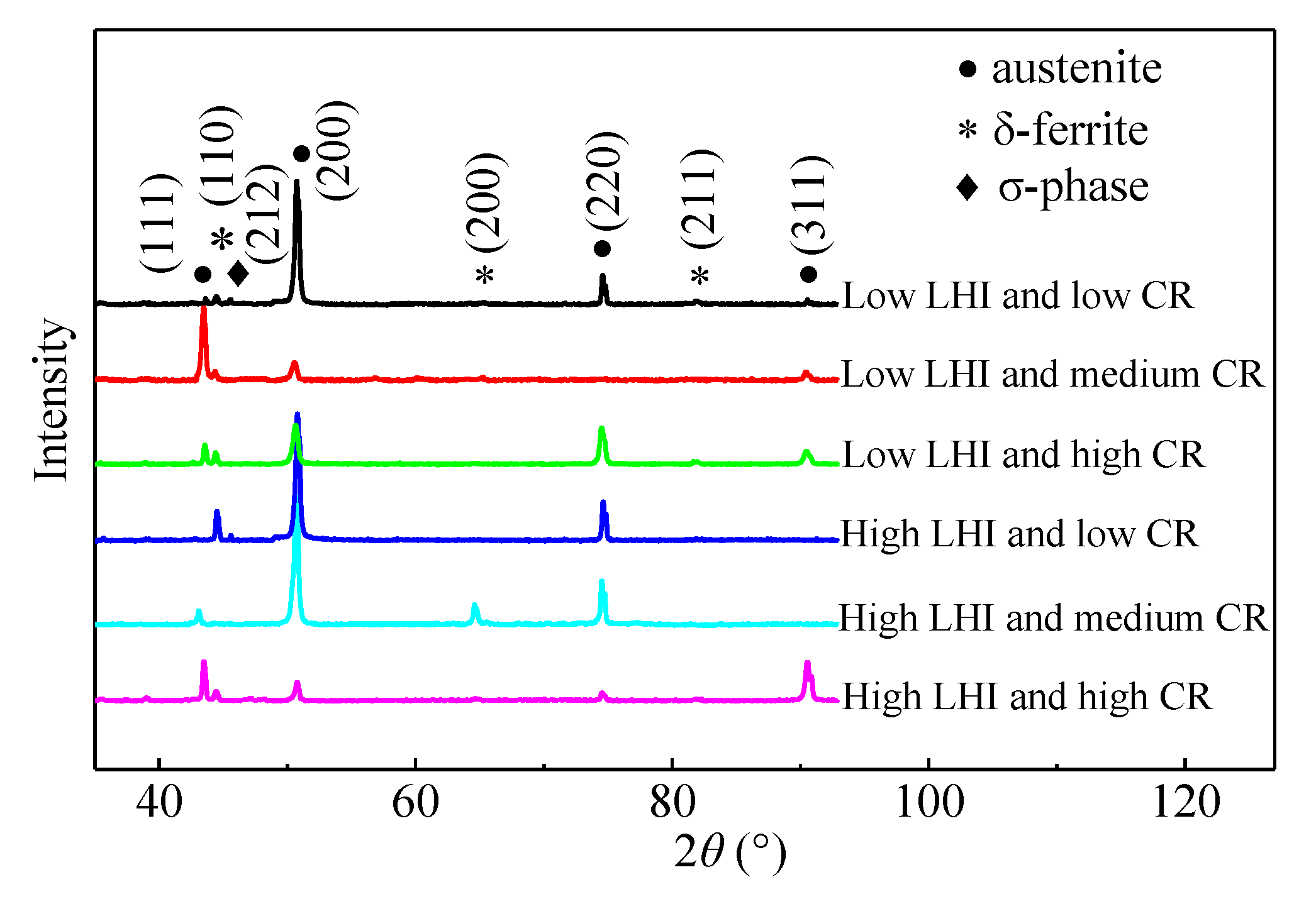
The microstructures of the studied steel are mainly composed of δ-ferrite and austenite dendrites. σ phases are formed on the δ-ferrite–austenite interface under low CR. The contents of δ-ferrite show an increasing trend with the decrease in CR. However, the effects of LEI on the δ-ferrite content are not apparent.
(2)
Under low LEI, the UTSes are 533, 553 and 573 MPa for the studied steel with low, medium and high CRs, respectively. With the increase in LEI, the UTSes decrease to 521, 530 and 553 MPa. The UTS and YS both show an increasing trend with the increase in CR or the decrease in LEI. However, the variation of elongation to fracture shows an opposite trend.
(3)
Numerous dimples and tearing edges are distributed on the fracture morphologies of the studied steel, indicating that the main fracture mechanism is the micro-voids-induced ductile fracture. The dimples are relatively deep for the studied steel under high LEI compared with that under low LEI, and the dimple size decreases with the CR increasing. For the studied steel under low LEI, the cracks are induced by the coalescence of pores. However, the cracks in the studied steel under high LEI are result from the dislocations piling up around δ-ferrite.

Author Contributions

Investigation, P.L.; data curation, J.M.; writing—original draft preparation, P.L.; writing—review and editing, D.W. and Y.L.; supervision, D.W. and Z.Z.; funding acquisition, J.L. All authors have read and agreed to the published version of the manuscript.

Funding

This research was funded by National Key R&D Program of China (No. 2018YFB1106501, 2018YFB1106505), National Natural Science Foundation of China (No. 51905190, 52075197, 51905098), and the Fundamental Research Funds for the Central Universities, China (No. 2019kfyXJJS001).

Institutional Review Board Statement

Not applicable.

Informed Consent Statement

Not applicable.

Data Availability Statement

The study did not report any data.

Acknowledgments

The authors appreciate the Analytical and Testing Center of Huazhong University of Science and Technology. The authors acknowledge Yan Zhu in Micro and Nano Fabrication and Measurement Laboratory for the support in experiment.

Conflicts of Interest

The authors declare no conflict of interest.

Nomenclature

LEIlinear energy inputCRcooling rate
AMadditive manufacturingWAAMwire arc additive manufacturing
EBMelectron beam meltingLPBFlaser powder-based fusion
DLDdirect laser depositionCMTcold metal transfer
OMoptical microscopeXRDX-ray diffraction
V s moving speed of solid–liquid interface V welding speed
γ material constant related to the adopted material and local acoustic speed. Δ T k undercooling degree of the interface front
θ the angle between V and V s g 0 Initial grain size
g ultimate grain size Q thermal activation energy
R molar gas constant K 1 material constant
T 0 preheating temperature T p peak temperature
λ thermal conductivity τ the time suitable for grain growth
qlinear energy inputYSyield strength
UTSultimate tensile strength

References

  1. Zhang, J.S.; Zhou, J.; Wang, Q.Y.; Xiao, G.Q.; Quan, G.Z. Process planning of automatic wire arc additive remanufacturing for hot forging die. Int. J. Adv. Manuf. Tech. 2020, 109, 1613–1623. [Google Scholar] [CrossRef]
  2. Umezu, S.; Sato, H. Best of both worlds: A novel, environment-friendly approach to 3D printing metal–plastic hybrid structures. Reinf. Plast. 2021, 65, 53–55. [Google Scholar] [CrossRef]
  3. Williams, S.W.; Martina, F.; Addison, A.C.; Ding, J.; Pardal, G.; Colegrove, P. Wire + Arc additive manufacturing. Mater. Sci. Technol. 2016, 32, 641–647. [Google Scholar] [CrossRef] [Green Version]
  4. Godec, M.; Zaefferer, S.; Podgornik, B.; Šinko, M.; Tchernychova, E. Quantitative multiscale correlative microstructure analysis of additive manufacturing of stainless steel 316L processed by selective laser melting. Mater. Charact. 2020, 160, 110074. [Google Scholar] [CrossRef]
  5. Khosravani, M.R.; Reiniche, T.E. Effects of raster layup and printing speed on strength of 3D-printed structural components. Procedia Struct. Integr. 2020, 28, 720–725. [Google Scholar] [CrossRef]
  6. Bermingham, M.J.; Kent, D.; Zhan, H.; Stjohn, D.H.; Dargusch, M.S. Controlling the microstructure and properties of wire arc additive manufactured Ti-6Al-4V with trace boron additions. Acta Mater. 2015, 91, 289–303. [Google Scholar] [CrossRef]
  7. Wen, D.X.; Long, P.; Li, J.J.; Huang, L.; Zheng, Z.Z. Effects of linear heat input on microstructure and corrosion behavior of an austenitic stainless steel processed by wire arc additive manufacturing. Vacuum 2020, 173, 109131. [Google Scholar] [CrossRef]
  8. Song, X.; Feih, S.; Zhai, W.; Sun, C.N.; Li, F.; Maiti, R.; Wei, J.; Yang, Y.; Oancea, V.; Romano Brandt, L.; et al. Advances in additive manufacturing process simulation: Residual stresses and distortion predictions in complex metallic components. Mater. Des. 2020, 193, 108779. [Google Scholar] [CrossRef]
  9. Zeng, Z.; Cong, B.; Oliveira, J.P.; Ke, W.; Schell, N.; Peng, B.; Qi, Z.W.; Ge, F.; Zhang, W.; Ao, S.S. Wire and arc additive manufacturing of a Ni-rich NiTi shape memory alloy: Microstructure and mechanical properties. Addit. Manuf. 2020, 32, 101051. [Google Scholar] [CrossRef]
  10. Astafurova, E.G.; Panchenko, M.Y.; Moskvina, V.A.; Maier, G.G.; Astafurov, S.V.; Melnikov, E.V.; Fortuna, A.S.; Reunova, K.A.; Rubtsov, V.E.; Kolubaev, E.A. Microstructure and grain growth inhomogeneity in austenitic steel produced by wire-feed electron beam melting: The effect of post-building solid-solution treatment. J. Mater. Sci. 2020, 50, 9211–9224. [Google Scholar] [CrossRef]
  11. Martina, F.; Mehnen, J.; Williams, S.W.; Colegrove, P.; Wang, F. Investigation of the benefits of plasma deposition for the additive layer manufacture of Ti-6Al-4V. J. Mater. Process. Technol. 2012, 212, 1377–1386. [Google Scholar] [CrossRef] [Green Version]
  12. Portella, Q.; Chemkhi, M.; Retraint, D. Influence of surface mechanical attrition treatment (SMAT) post-treatment on microstructural, mechanical and tensile behaviour of additive manufactured AISI 316L. Mater. Charact. 2020, 167, 110463. [Google Scholar] [CrossRef]
  13. Leicht, A.; Rashidi, M.; Klement, U.; Hryha, E. Effect of process parameters on the microstructure, tensile strength and productivity of 316L parts produced by laser powder bed fusion. Mater. Charact. 2020, 159, 110016. [Google Scholar] [CrossRef]
  14. Wang, K.; Wen, D.X.; Li, J.J.; Zheng, Z.Z.; Xiong, Y.B. Hot deformation behaviors of low-alloyed ultrahigh strength steel 30CrMnSiNi2A: Microstructure evolution and constitutive modeling. Mater. Today Commun. 2021, 26, 102009. [Google Scholar] [CrossRef]
  15. Xu, X.F.; Ganguly, S.; Ding, J.L.; Guo, S.; Williams, S.; Martina, F. Microstructural evolution and mechanical properties of maraging steel produced by wire + arc additive manufacture process. Mater. Charact. 2018, 143, 152–162. [Google Scholar] [CrossRef]
  16. Panchenko, O.; Kurushkin, D.; Mushnikov, I.; Khismatullin, A.; Popovich, A. A high-performance WAAM process for Al–Mg–Mn using controlled short-circuiting metal transfer at increased wire feed rate and increased travel speed. Mater. Des. 2020, 195, 109040. [Google Scholar] [CrossRef]
  17. Kok, Y.; Tan, X.P.; Wang, P.; Nai, M.L.S.; Loh, N.H.; Liu, E.; Tor, S.B. Anisotropy and heterogeneity of microstructure and mechanical properties in metal additive manufacturing: A critical review. Mater. Des. 2018, 139, 565–586. [Google Scholar] [CrossRef]
  18. Lam, T.F.; Xiong, Y.; Dharmawan, A.G.; Foong, S.; Soh, G.S. Adaptive process control implementation of wire arc additive manufacturing for thin-walled components with overhang features. Int. J. Adv. Manuf. Tech. 2020, 108, 1061–1071. [Google Scholar] [CrossRef]
  19. Rodriguez, N.; Vázquez, L.; Huarte, I.; Arruti, E.; Tabernero, I.; Alvarez, P. Wire and arc additive manufacturing: A comparison between CMT and TopTIG processes applied to stainless steel. Weld. World. 2018, 62, 1083–1096. [Google Scholar] [CrossRef]
  20. Oliveira, J.P.; Santos, T.G.; Miranda, R.M. Revisiting fundamental welding concepts to improve additive manufacturing: From theory to practice. Prog. Mater. Sci. 2020, 107, 100590. [Google Scholar] [CrossRef]
  21. Zhang, C.; Li, Y.F.; Gao, M.; Zeng, X.Y. Wire arc additive manufacturing of Al-6Mg alloy using variable polarity cold metal transfer arc as power source. Mater. Sci. Eng. A 2018, 711, 415–423. [Google Scholar] [CrossRef]
  22. Davis, A.E.; Kennedy, J.R.; Ding, J.; Prangnell, P.B. The effect of processing parameters on rapid-heating β recrystallization in inter-pass deformed Ti-6Al-4V wire-arc additive manufacturing. Mater. Charact. 2020, 163, 110298. [Google Scholar] [CrossRef]
  23. Wang, L.L.; Xue, J.X.; Wang, Q. Correlation between arc mode, microstructure, and mechanical properties during wire arc additive manufacturing of 316L stainless steel. Mater. Sci. Eng. A 2019, 751, 183–190. [Google Scholar] [CrossRef]
  24. Chen, X.H.; Li, J.; Cheng, X.; He, B.; Wang, H.M.; Huang, Z. Microstructure and mechanical properties of the austenitic stainless steel 316L fabricated by gas metal arc additive manufacturing. Mater. Sci. Eng. A 2017, 703, 567–577. [Google Scholar] [CrossRef]
  25. Qiu, Z.J.; Wu, B.T.; Zhu, H.L.; Wang, Z.Y.; Hellier, A.; Ma, Y.; Li, H.J.; Muransky, O.; Wexler, D. Microstructure and mechanical properties of wire arc additively manufactured Hastelloy C276 alloy. Mater. Des. 2020, 195, 109007. [Google Scholar] [CrossRef]
  26. Ščetinec, A.; Klobčar, D.; Bračun, D. In-process path replanning and online layer height control through deposition arc current for gas metal arc based additive manufacturing. J. Manuf. Process. 2021, 64, 1169–1179. [Google Scholar] [CrossRef]
  27. Gu, J.L.; Gao, M.J.; Yang, S.L.; Bai, J.; Ding, J.L.; Fang, X.W. Pore formation and evolution in wire + arc additively manufactured 2319 Al alloy. Addit. Manuf. 2019, 30, 100900. [Google Scholar] [CrossRef]
  28. Ren, L.L.; Gu, H.M.; Wang, W.; Wang, S.; Li, C.; Wang, Z.B.; Zhai, Y.C.; Ma, P.H. Effect of Mg Content on Microstructure and Properties of Al–Mg Alloy Produced by the Wire Arc Additive Manufacturing Method. Materials 2019, 12, 4160. [Google Scholar] [CrossRef] [Green Version]
  29. Zhang, C.; Gao, M.; Zeng, X.Y. Workpiece vibration augmented wire arc additive manufacturing of high strength aluminum alloy. J. Mater. Process. Technol. 2019, 271, 85–92. [Google Scholar] [CrossRef]
  30. Dai, Y.L.; Yu, S.F.; Shi, Y.S.; He, T.Y.; Zhang, L.C. Wire and arc additive manufacture of high-building multi-directional pipe joint. Int. J. Adv. Manuf. Technol. 2018, 96, 2389–2396. [Google Scholar] [CrossRef]
  31. Yang, D.Q.; Wang, G.; Zhang, G.J. Thermal analysis for single-pass multi-layer GMAW based additive manufacturing using infrared thermography. J. Mater. Process. Technol. 2017, 244, 215–224. [Google Scholar] [CrossRef]
  32. Xiong, J.; Lei, Y.Y.; Chen, H.; Zhang, G.J. Fabrication of inclined thin-walled parts in multi-layer single-pass GMAW-based additive manufacturing with flat position deposition. J. Mater. Process. Technol. 2017, 240, 397–403. [Google Scholar] [CrossRef]
  33. Wang, J.F.; Sun, Q.J.; Wang, H.; Liu, J.P.; Feng, J.C. Effect of location on microstructure and mechanical properties of additive layer manufactured Inconel 625 using gas tungsten arc welding. Mater. Sci. Eng. A 2016, 676, 395–405. [Google Scholar] [CrossRef]
  34. Lin, J.J.; Lv, Y.H.; Liu, Y.X.; Xu, B.S.; Sun, Z.; Li, Z.G.; Wu, Y.X. Microstructural evolution and mechanical properties of Ti-6Al-4V wall deposited by pulsed plasma arc additive manufacturing. Mater. Des. 2016, 102, 30–40. [Google Scholar] [CrossRef]
  35. Guo, J.; Zhou, Y.; Liu, C.M.; Wu, Q.R.; Chen, X.P.; Lu, J.P. Wire arc additive manufacturing of AZ31 magnesium alloy: Grain refinement by adjusting pulse frequency. Materials 2016, 9, 823. [Google Scholar] [CrossRef] [PubMed] [Green Version]
  36. Fousová, M.; Dvorský, D.; Michalcová, A.; Vojtěch, D. Changes in the microstructure and mechanical properties of additively manufactured AlSi10Mg alloy after exposure to elevated temperatures. Mater. Charact. 2018, 137, 119–126. [Google Scholar] [CrossRef]
  37. Horgar, A.; Fostervoll, H.; Nyhus, B.; Ren, X.; Eriksson, M.; Akselsen, O.M. Additive manufacturing using WAAM with AA5183 wire. J. Mater. Process. Technol. 2018, 259, 68–74. [Google Scholar] [CrossRef]
  38. Ding, D.H.; Pan, Z.X.; Duin, S.V.; Li, H.J.; Shen, C. Fabricating superior NiAl bronze components through wire arc additive manufacturing. Materials 2016, 9, 652. [Google Scholar] [CrossRef] [Green Version]
  39. Shen, C.; Pan, Z.; Ding, D.H.; Yuan, L.; Nie, N.; Wang, Y.; Luo, D.Z.; Cuiuri, D.; Duin, S.V.; Li, H.J. The influence of post-production heat treatment on the multi-directional properties of nickel-aluminum bronze alloy fabricated using wire-arc additive manufacturing process. Addit. Manuf. 2018, 23, 411–421. [Google Scholar] [CrossRef]
  40. Zhang, X.; Martina, F.; Ding, J.; Wang, X.; Williams, S.W. Fracture toughness and fatigue crack growth rate properties in wire + arc additive manufactured Ti-6Al-4V. Fatigue Fract. Eng. Mater. Struct. 2017, 40, 790–803. [Google Scholar] [CrossRef] [Green Version]
  41. Wu, Q.R.; Mukherjee, T.H.; Liu, C.M.; Lu, J.P.; DebRoy, T. Residual stresses and distortion in the patterned printing of titanium and nickel alloys. Addit. Manuf. 2019, 29, 100808. [Google Scholar] [CrossRef]
  42. Haden, C.V.; Zeng, G.; Carter, F.M.; Ruhl, C.; Krick, B.A.; Harlow, D.G. Wire and arc additive manufactured steel: Tensile and wear properties. Addit. Manuf. 2017, 16, 115–123. [Google Scholar] [CrossRef]
  43. Rodrigues, T.A.; Duarte, V.; Avila, J.A.; Santos, T.G.; Miranda, R.M.; Oliveira, J.P. Wire and arc additive manufacturing of HSLA steel: Effect of thermal cycles on microstructure and mechanical properties. Addit. Manuf. 2019, 27, 440–450. [Google Scholar] [CrossRef]
  44. Shen, C.; Pan, Z.X.; Cuiuri, D.; Duin, S.V.; Luo, D.Z.; Dong, B.S.; Li, H.J. Influences of postproduction heat treatment on Fe3Al-based iron aluminide fabricated using the wire-arc additive manufacturing process. Int. J. Adv. Manuf. Technol. 2018, 97, 335–344. [Google Scholar] [CrossRef]
  45. Wang, J.; Pan, Z.X.; Wei, L.L.; He, S.; Cuiuri, D.; Li, H.J. Introduction of ternary alloying element in wire arc additive manufacturing of titanium aluminide intermetallic. Addit. Manuf. 2019, 27, 236–245. [Google Scholar] [CrossRef]
  46. Bobbili, R.; Madhu, V. Physically-based constitutive model for flow behavior of a Ti-22Al-25Nb alloy at high strain rates. J. Alloys Compd. 2018, 762, 842–848. [Google Scholar] [CrossRef]
  47. Momeni, A.; Abbasi, S.M.; Sadeghpour, S. A comparative study on the hot deformation behavior of Ti-5Al-5Mo-5V-3Cr and newly developed Ti-4Al-7Mo-3V-3Cr alloys. Vacuum 2019, 161, 410–418. [Google Scholar] [CrossRef]
  48. Chen, M.S.; Li, K.K.; Lin, Y.C.; Yuan, W.Q. An improved kinetics model to describe dynamic recrystallization behavior under inconstant deformation conditions. J. Mater. Res. 2016, 31, 2994–3003. [Google Scholar] [CrossRef]
  49. Lin, Y.C.; Zhu, X.H.; Dong, W.Y.; Yang, H.; Xiao, Y.W.; Kotkunde, N. Effects of deformation parameters and stress triaxiality on the fracture behaviors and microstructural evolution of an Al-Zn-Mg-Cu alloy. J. Alloys Compd. 2020, 832, 154988. [Google Scholar] [CrossRef]
  50. Wang, C.; Liu, T.G.; Zhu, P.; Lu, H.Y.; Shoji, T. Study on microstructure and tensile properties of 316L stainless steel fabricated by CMT wire and arc additive manufacturing. Mater. Sci. Eng. A 2020, 796, 140006. [Google Scholar] [CrossRef]
  51. Hu, Z.; Nagarajan, B.; Song, X.; Huang, R.; Zhai, W.; Wei, J. Formation of SS316L single tracks in micro selective laser melting: Surface, geometry, and defects. Adv. Mater. Sci. Eng. 2019, 2019, 9451406. [Google Scholar] [CrossRef] [Green Version]
  52. Yadollahi, A.; Shamsaei, N.; Thompson, S.M.; Seely, D.W. Effects of process time interval and heat treatment on the mechanical and microstructural properties of direct laser deposited 316L stainless steel. Mater. Sci. Eng. A 2015, 644, 171–183. [Google Scholar] [CrossRef]
  53. Guo, P.; Zou, B.; Huang, C.Z.; Gao, H.B. Study on microstructure, mechanical properties and machinability of efficiently additive manufactured AISI 316L stainless steel by high-power direct laser deposition. J. Mater. Process. Technol. 2017, 240, 12–22. [Google Scholar] [CrossRef]
  54. Ziętala, M.; Durejko, T.; Polański, M.; Kunce, I.; Płociński, T.; Zieliński, W.; Łazińska, M.; Stępniowski, W.; Czujko, T.; Kurzydłowski, K.J.; et al. The microstructure, mechanical properties and corrosion resistance of 316L stainless steel fabricated using laser engineered net shaping. Mater. Sci. Eng. A 2016, 677, 1–10. [Google Scholar] [CrossRef]
  55. Chen, X.H.; Li, J.; Cheng, X.; Wang, H.M.; Huang, Z. Effect of heat treatment on microstructure, mechanical and corrosion properties of austenitic stainless steel 316L using arc additive manufacturing. Mater. Sci. Eng. A 2018, 715, 307–314. [Google Scholar] [CrossRef]
  56. Yan, X.L.; Zhang, X.C.; Tu, S.T.; Mannan, S.L.; Xuan, F.Z.; Lin, Y.C. Review of creep–fatigue endurance and life prediction of 316 stainless steels. Int. J. Press. Vessel. Pip. 2015, 126–127, 17–28. [Google Scholar] [CrossRef]
  57. Bartolomeu, F.; Faria, S.; Carvalho, O.; Pinto, E.; Alves, N.; Silva, F.S.; Miranda, G. Predictive models for physical and mechanical properties of Ti6Al4V produced by Selective Laser Melting. Mater. Sci. Eng. A 2016, 663, 181–192. [Google Scholar] [CrossRef]
  58. Xu, D.M.; Li, G.Q.; Wan, X.L.; Misra, R.D.K.; Zhang, X.G.; Xu, G.; Wu, K.M. The effect of annealing on the microstructural evolution and mechanical properties in phase reversed 316LN austenitic stainless steel. Mater. Sci. Eng. A 2018, 720, 36–48. [Google Scholar] [CrossRef]
  59. Wu, C.F.; Li, S.L.; Zhang, C.H.; Wang, X.T. Microstructural evolution in 316LN austenitic stainless steel during solidification process under different cooling rates. J. Mater. Sci. 2016, 51, 2529–2539. [Google Scholar] [CrossRef] [Green Version]
  60. Xiao, W.K.; Zhu, L.; Zhang, F.J.; Dai, K.S.; Zai, X.; Yang, X.; Chen, B.J. Effect of heat input on cryogenic toughness of 316LN austenitic stainless steel NG-MAG welding joints with large thickness. Mater. Des. 2015, 86, 160–167. [Google Scholar] [CrossRef]
  61. Dai, K.S.; He, P.; Zhu, L.; Zhang, F.J.; Chen, F.Y.; Zhai, X.; Xiao, W.K. Effect of solution treatment on microstructure and cryogenic toughness of 316LN austenite stainless steel weld metal welded by NG-MAG arc welding. Fusion Eng. Des. 2017, 125, 178–188. [Google Scholar] [CrossRef]
  62. Yang, Y.H.; Qian, H. Investigation on aging σ-phase precipitation kinetics and pitting corrosion of 22 pct Cr economical duplex stainless steel with Mn addition, Metall. Mater. Trans. A 2018, 49, 3184–3197. [Google Scholar] [CrossRef]
  63. Wen, D.X.; Yue, T.Y.; Xiong, Y.B.; Wang, K.; Wang, J.K.; Zheng, Z.Z.; Li, J.J. High-temperature tensile characteristics and constitutive models of ultrahigh strength steel. Mater. Sci. Eng. A 2021, 803, 140491. [Google Scholar] [CrossRef]
  64. Serafini, F.L.; Peruzzo, M.; Krindges, I.; Ordoñez, M.F.C.; Rodrigues, D.; Souza, R.M.; Farias, M.C.M. Microstructure and mechanical behavior of 316L liquid phase sintered stainless steel with boron addition. Mater. Charact. 2019, 152, 253–264. [Google Scholar] [CrossRef]
  65. Brooks, J.A.; Williams, J.C.; Thompson, A.W. Microstructural origin of the skeletal ferrite morphology of austenitic stainless steel welds. Metall. Trans. A 1983, 14, 1271–1281. [Google Scholar] [CrossRef]
  66. Wang, D.; Song, C.H.; Yang, Y.Q.; Bai, Y.C. Investigation of crystal growth mechanism during selective laser melting and mechanical property characterization of 316L stainless steel parts. Mater. Des. 2016, 100, 291–299. [Google Scholar] [CrossRef]
  67. Wang, Z.Q.; Palmer, T.A.; Beese, A.M. Effect of processing parameters on microstructure and tensile properties of austenitic stainless steel 304L made by directed energy deposition additive manufacturing. Acta Mater. 2016, 110, 226–235. [Google Scholar] [CrossRef] [Green Version]
  68. Lin, Y.C.; Wu, Q.; Pang, G.D.; Jiang, X.Y.; He, D.G. Hot tensile deformation mechanism and dynamic softening behavior of Ti-6Al-4V alloy with thick lamellar microstructures. Adv. Eng. Mater. 2020, 22, 01901193. [Google Scholar] [CrossRef]
  69. Wen, D.X.; Wang, J.K.; Wang, K.; Xiong, Y.B.; Huang, L.; Zheng, Z.Z.; Li, J.J. Hot tensile deformation and fracture behaviors of a typical ultrahigh strength steel. Vacuum 2019, 169, 108863. [Google Scholar] [CrossRef]
  70. Lin, Y.C.; Deng, J.; Jiang, Y.Q.; Wen, D.X.; Liu, G. Effects of initial δ phase on hot tensile deformation behaviors and fracture characteristics of a typical Ni-based superalloy. Mater. Sci. Eng. A 2014, 598, 251–262. [Google Scholar] [CrossRef]
Figure 1. Cold metal transfer (CMT)-based wire arc additive manufacturing (WAAM) system.
Materials 14 01681 g001
Figure 2. Schematic description of the CMT-based WAAM system.
Materials 14 01681 g002
Figure 3. Position and dimension of tensile samples: (a) sample position within the additive manufacturing (AM) part (Y and Z denote the scanning direction and building direction, respectively); (b) detailed dimension of the tensile sample.
Materials 14 01681 g003
Figure 4. XRD patterns of the AM parts under different LEIs and cooling rates (CRs).
Materials 14 01681 g004
Figure 5. Macro-morphologies of the top region within the AM parts under: (a) low LEI; (b) high LEI.
Materials 14 01681 g005
Figure 6. Microstructures of the AM parts with: (a) low LEI and high CR; (b) low LEI and medium CR; (c) low LEI and low CR; (d) high LEI and high CR; (e) high LEI and medium CR; (f) high LEI and low CR.
Materials 14 01681 g006
Figure 7. Engineering stress–strain relationships of the studied steel under: (a) low LEI, (b) high LEI.
Materials 14 01681 g007
Figure 8. Histogram of mechanical properties of longitudinal tensile samples under different LEIs.
Materials 14 01681 g008
Figure 9. Longitudinal sectional morphologies of the vertical tensile samples under: (ac) low LEI; (df) high LEI. (b,c,e,f) are the magnified graphs of regions marked 1, 2, 3, 4 in (a,d).
Materials 14 01681 g009
Figure 10. Fracture surfaces of the vertical tensile samples under: (a,b) low LEI; and (c,d) high LEI.
Materials 14 01681 g010
Figure 11. Fracture surfaces of the longitudinal tensile samples under (a) low LEI and low CR; (b) low LEI and medium CR; (c) low LEI and high CR; (d) high LEI and low CR; (e) high LEI and medium CR; (f) high LEI and high CR.
Materials 14 01681 g011
Table 1. Chemical composition of ER316L stainless steel wire.
ElementCrNiMoMnSiCSPNFe
wt.%18.3912.52.251.690.810.020.0150.0150.013balance
Table 2. Processing parameters of WAAM used in this study. LEI: linear energy input.
GroupWire Feed Speed
(mm × s−1)
Travel Speed
(mm × s−1)
Voltage
(V)
Current
(A)
LEI
(J × mm)
Low LEI50814.4122219
High LEI83518.2162590
Table 3. δ-ferrite contents and primary dendrites spacing of the AM parts under different LEIs and CRs.
Microstructure CharacteristicsThe Studied Steel
Low LEI-
High CR
Low LEI-
Medium CR
Low LEI-
Low CR
High LEI-
High CR
High LEI-
Medium CR
High LEI-
Low CR
Primary dendrites spacing (μm)182127232732
δ-ferrite contents (%)17.316.214.517.716.213.2
Table 4. Summary of the mechanical properties of the studied steel under different LEIs and CRs.
Mechanical PropertiesThe Studied Steel
Low LEI-
High CR
Low LEI-
Medium CR
Low LEI-
Low CR
High LEI-
High CR
High LEI-
Medium CR
High LEI-
Low CR
Yield stress (MPa) 344 ± 5 321 ± 4 329 ± 6 328 ± 3 302 ± 2 282 ± 3
Ultimate tensile stress (MPa) 573 ± 8 553 ± 6 533 ± 7 553 ± 4 530 ± 6 521 ± 4
Elongation (%) 48.5 ± 0.4 47.5 ± 0.1 46.8 ± 0.3 49.7 ± 0.2 49.9 ± 0.2 48.7 ± 0.4
Publisher’s Note: MDPI stays neutral with regard to jurisdictional claims in published maps and institutional affiliations.

