Kalman-Filter-Based Tension Control Design for Industrial Roll-to-Roll System

Graduate School of Mechanical Engineering, Yeungnam University, 280 Daehak-ro, Gyeongsan 38541, Korea
*
Author to whom correspondence should be addressed.
†
These authors contributed equally to this work.
Algorithms 2019, 12(4), 86; https://0-doi-org.brum.beds.ac.uk/10.3390/a12040086
Submission received: 2 April 2019
/
Revised: 17 April 2019
/
Accepted: 22 April 2019
/
Published: 24 April 2019
(This article belongs to the Special Issue Algorithms for PID Controller 2019)
Abstract
:This paper presents a robust and precise tension control method for a roll-to-roll (R2R) system. In R2R processing, robust and precise tension control is very important because improper web tension control leads to deterioration in the quality of web material. However, tension control is not easy because the R2R system has a model variation in which the inertia of the web in roll form is changed and external disturbances caused by web slip and crumpled web. Therefore, a disturbance observer (DOB) was proposed to achieve robustness against model variations and external disturbances. DOB is a robust control method widely used in various fields because of its simple structure and excellent performance. Moreover, the web passes through various process steps to achieve the finished product in the R2R process. Particularly, it is important to track the tension when magnitude of the tension varies during process. Feedforward (FF) controller was applied to minimize the tracking error in the transient section where tension changes. Moreover, the signal processing of a sensor using the Kalman filter (KF) in the R2R system greatly improved control performance. Finally, the effectiveness of the proposed control scheme is discussed using experimental results.
1. Introduction
Roll-to-roll (R2R) technology has recently attracted a great deal of attention for the mass production of electronic devices in the field of display and battery [1]. The R2R machine is composed of rewinder, unwinder, and feeder motors. The rewinder motor is used to wind the web made in roll form with the desired tension. On the other hand, the unwinder motor is used to unwind the web. The feeder motor is used for web transfer motions at the proper speed.
In the R2R system, tension control is usually achieved by using a load cell or dancer roll. In R2R processing, robust and precise tension control is essential because it affects the quality of the web materials. The web has flexible substrates including metal foils, glass, and ceramics. In particular, these substrates used in electronic devices require precise tension control because coating and printing thickness variation occurs despite minute tension changes, resulting in changes in electrical properties.
Some studies have investigated the tension control of R2R equipment. In 1993, Ebler investigated web tension control with dancer rolls and load cells [2]. The two different systems have been analyzed and experimental results have been provided. In 1998, K. Okada designed an adaptive fuzzy control for a web tension control system [3]. In 2002, Koç analyzed modeling and robust control of a winding system [4]. The effectiveness of robust control strategy in a web system is compared to a proportional-integral-derivative (PID) controller commonly used in the industry. In 2007, Shin presented the effect of tension on the lateral dynamics and control of a moving web [5]. Experimental studies of the lateral motion of a web were carried out and a cross-couple controller was proposed, which automatically tunes the proportional and integral gains of a lateral-position controller according to the web tension.
However, despite these numerous studies, tension control is not easy because it has model variations in which the inertia of the web in roll form is changed and external disturbances caused by web slip and crumpled web. To achieve robustness against model variations and external disturbances, robust control such as a disturbance observer (DOB) is required [6,7,8,9,10]. DOB has been widely used as an effective methodology to overcome model uncertainty and external disturbance. Eum proposed DOB for the robust tension control of the R2R system [11].
Unlike previous studies, we propose feedforward (FF) controller and signal processing technology using the Kalman filter (KF) to improve tension control performance. The web is continuously subjected to various processes for the final production. Particularly, it is important to control the tension when magnitude of the tension varies during process. To improve tracking performance in the transient section where tension changes, the feedforward controller was applied [12,13,14]. Moreover, a high-price load cell with a highly accurate and noiseless signal should be used to improve tension control performance in the R2R system. In order to reduce costs, which is an unavoidable issue in today’s industry, the KF algorithm was suggested for signal processing [15,16,17,18]. Almost all load cell applications require filtering to remove noise from the measured signal. A signal filter has a trade-off between noise suppression and phase delay. Phase delay may cause a change in phase margin, stability of the whole system, and accuracy of present information in the signal. Unlike the low pass filter (LPF), a conventional signal filter, the KF minimizes the phase delay [19]. The KF is capable of processing the signal by overcoming the phase delay problem even using a low-cost load cell.
This paper suggests a robust and precise tension control method for the R2R system and is organized as follows. In Section 2, we suggest dynamic model of the R2R system and how to identify the nominal parameters of the system experimentally. In Section 3, the design of a signal filter is presented. In Section 4, the proposed tension control for the R2R system is introduced and robust stability is shown using the small-gain theorem [20,21,22]. The performance of the proposed control method is verified with experimental results in Section 5. Finally, Section 6 provides some concluding remarks.
2. System Modeling
In this section, modeling of the suggested R2R system is introduced. Moreover, we suggest how to identify the nominal parameters of the system through an experiment [23].
2.1. Dynamic System Model
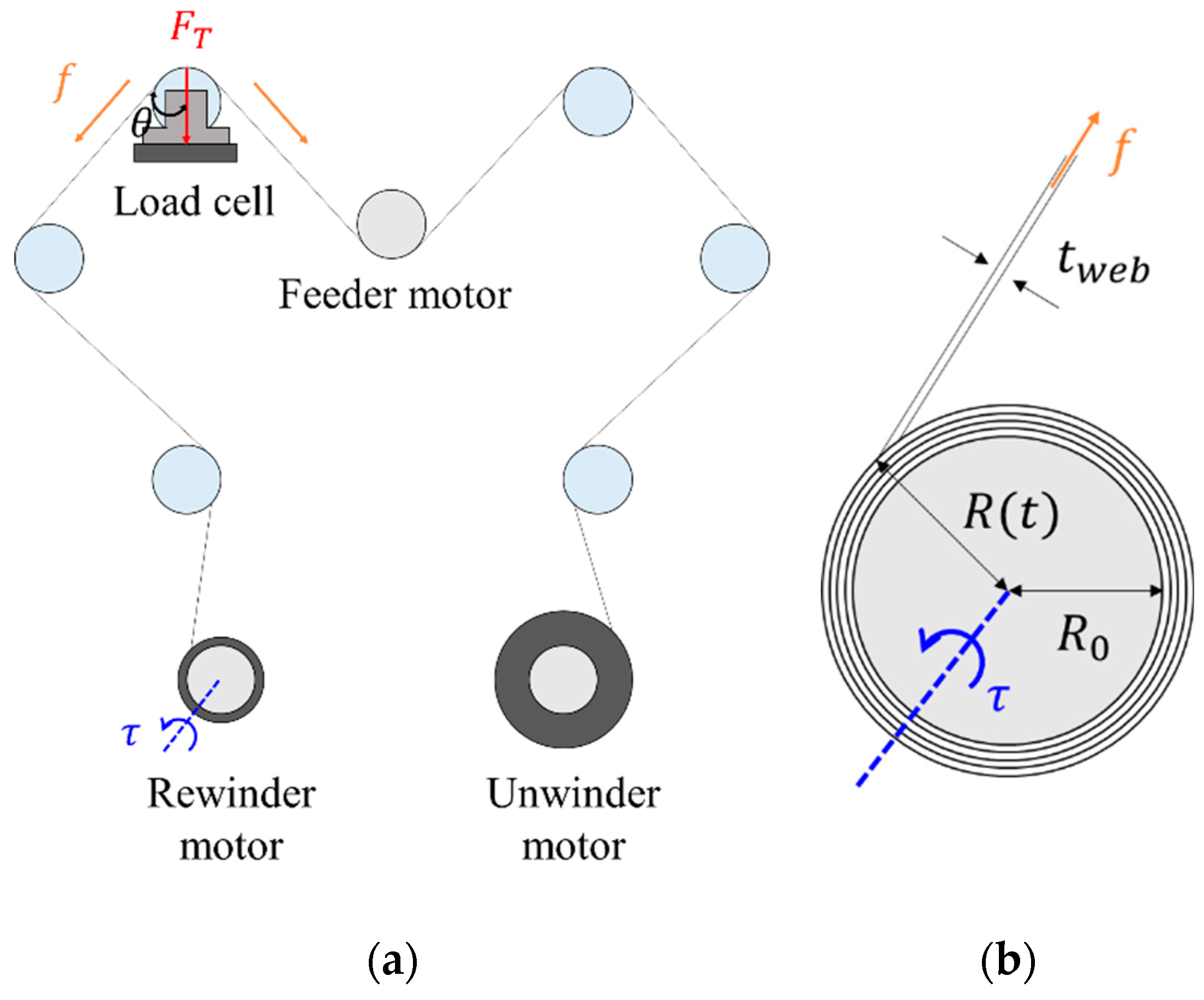
As shown in Figure 1a, the web is fed at a constant speed by the feeder motor and is wound with the proper tension by the rewinder motor. The web dynamics Equation (1) and roll-to-roll system dynamics model Equations (2)–(8) used throughout the paper are described in References [11] and [24]. The web can be represented in terms of spring and dashpot elements, which are described by the elasticity modulus E and the viscosity modulus . Lumped parameter models are expressed as the Kelvin-Voigt model for web dynamics. In the case of the Kelvin-Voigt model, the web tensile stress is expressed as follows:
where is web strain. Then web tension force is related to the web tensile stress and web cross sectional area as follows:
The load cell signal output varies depending on the web tension force . According to Figure 1a,b, it is expressed as follows:
where is external disturbance. Here, the load cell signal feeds back to control the web tension force . The torque generated by the rewinder motor is related to the web tension force as follows:
where is the radius of the web, is the initial radius of the web, is the web thickness, and is the angular position of the rewinder motor. The transfer function of the system from torque input to load cell signal output is calculated as follows:
where P is the actual plant. Finally, we designed the plant as a first order lag element because it is a simple structure and represents a system with time lag. It is expressed as follows:
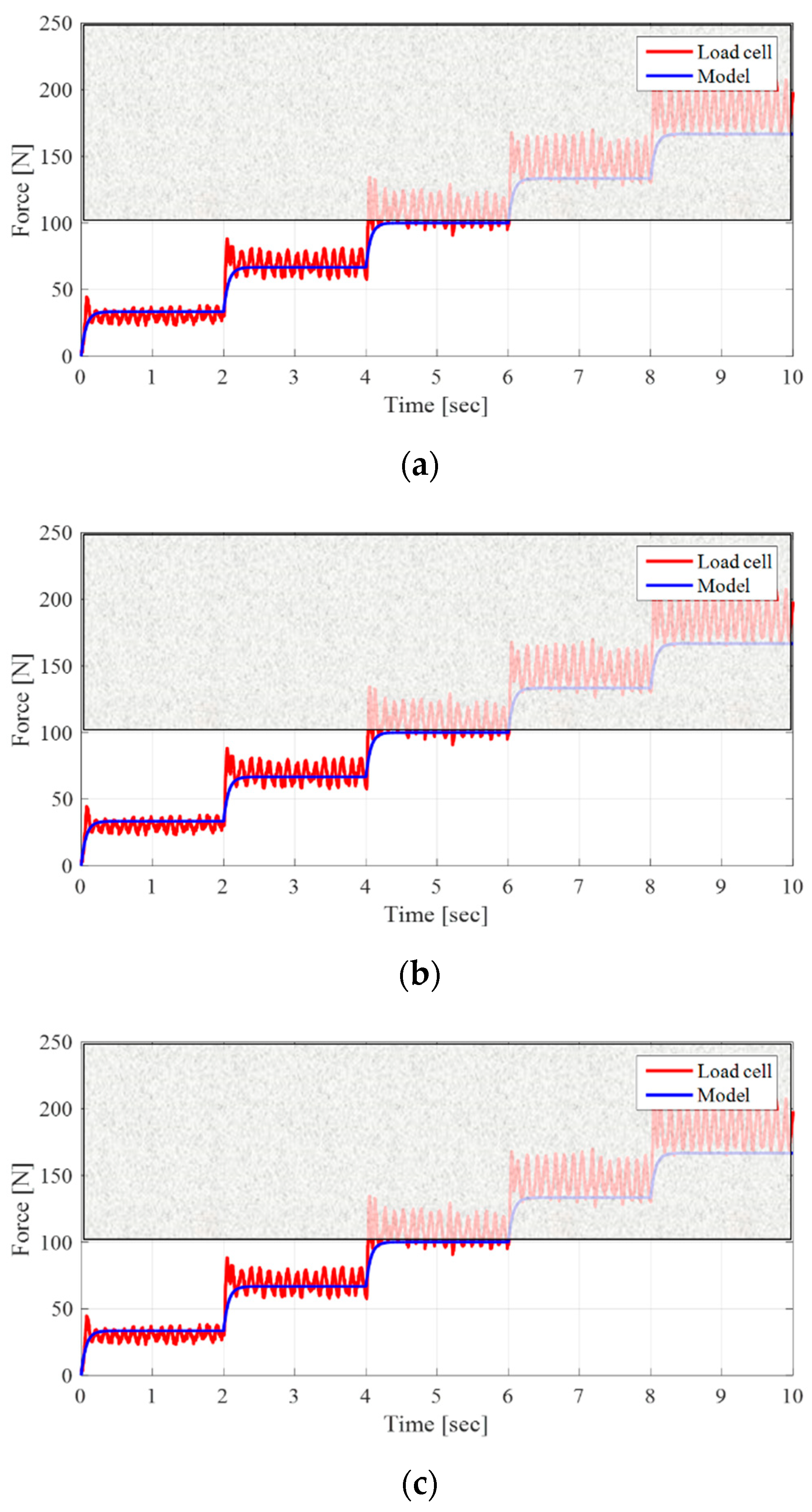
where is a time constant. The nominal model was obtained using an experimental method known as system identification, which develops mathematical models of dynamic systems from the measured input and output data of the system. The process of accurately obtaining a nominal model is important. Because the proposed KF in Section 3 and the tension controller, FF, and DOB in Section 4 largely vary in performance, depending on how accurately the nominal model is obtained, the experiment was carried out in three cases depending on the state of the film being wound. When step input with various magnitudes is applied to the system, the dynamic model is determined through the output data measured by the load cell. As shown in Figure 2, we focused on the characteristics of the system by 100 N because the experiment was performed from 0 N to 100 N.
3. Design of a Signal Filter
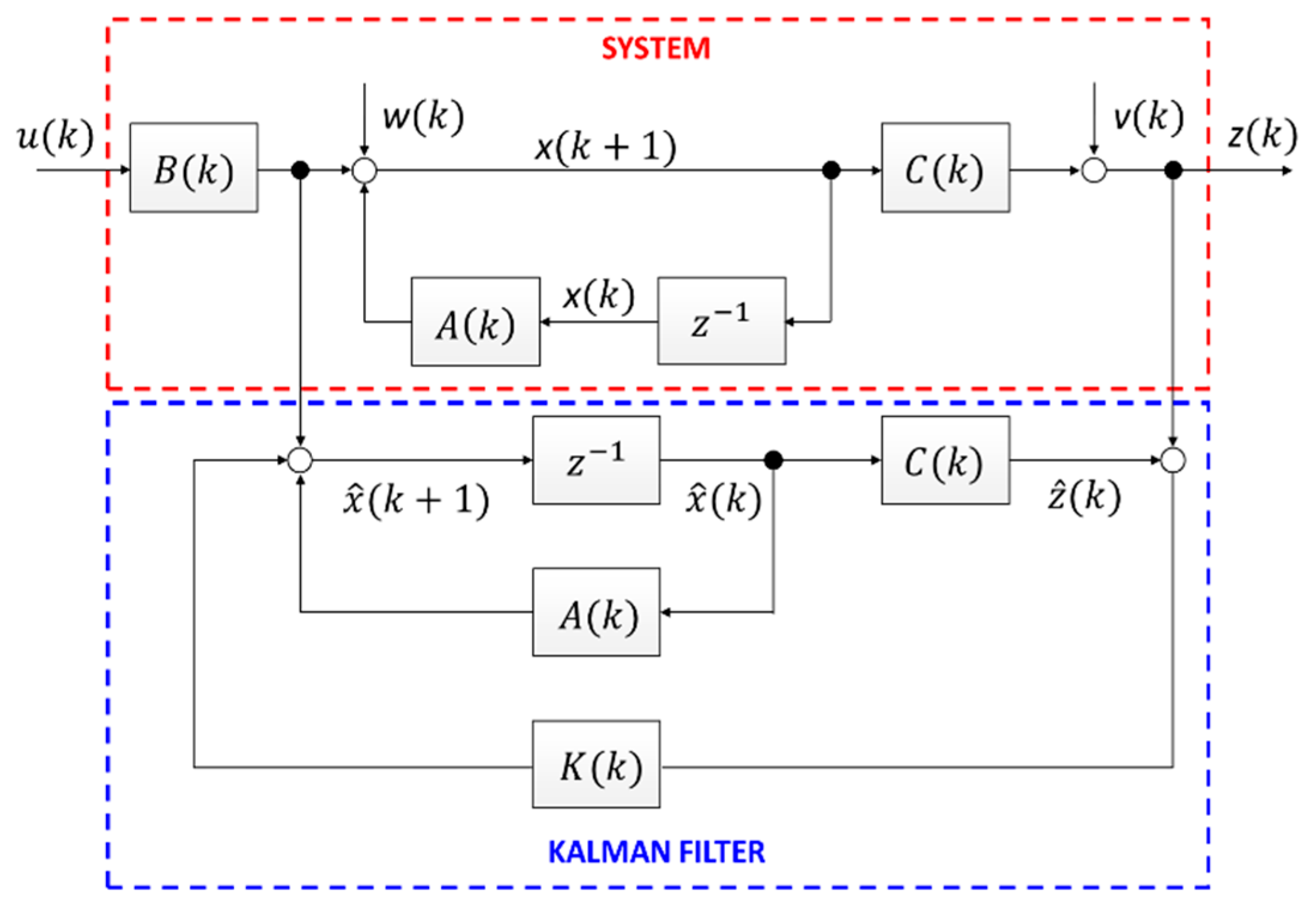
Signal processing of the sensor using a filter is essential to achieve precise control. Filters have a trade-off between noise reduction and phase response, so the more noise is reduced, the higher phase delay. The phase delay has an adverse effect on the phase margin and stability of the system. In this paper, it was possible not only to eliminate the noise contained in the observed data but also to minimize the phase delay by using the KF. The KF is an optimal estimation method that finds the true value of variables from a set of noisy measurements. In this section, we introduce how to design the KF and signal processing results. The design procedure of the KF is as follows. Firstly, the state space model of the linear system should be constructed. Subsequently, the state variables of the system are estimated by the KF algorithm using the state space model and measured values of the target system. The KF algorithm has two steps: prediction process and estimation process. Figure 3 illustrates the relationship of the KF with the actual system [15].
3.1. Linear State Space Model
To design a KF, the linear state space model must be first obtained by modeling the target system. The performance of the KF depends largely on how similar the system model is to the actual system. Equation (8) can be described by the following differential equation:
where is the nominal radius of the web and is the sensor noise. Defining the state variables = , the state differential equation is
where x is the state of the system, z is the output of the system, u is the system input, w is the system noise, and v is the measurement noise.
3.2. Kalman Filter Algorithm
The KF algorithm is divided into two stages: prediction process and correction process. Based on the system model variables A and Q, the prediction process guesses how the estimated value changes when the time changes from to . A is the system matrix and Q is the covariance matrix of W. Depending on how the system model variables, such as A, Q, R, and H, are selected, the performance of KF varies. Equations (12)–(17) refer to the KF algorithm mentioned in Reference [15]. The following equation is the state variable and error covariance, which are the predicted variables as follows:
In the correction process, the KF’s final estimated value is calculated using the system model variables H and R. H is the measurement matrix and R is the covariance matrix of V. The KF computes the final estimated value by adding the predicted value and the current measurement multiplied by the appropriate weight value as follows:
Here, the weight value is known as a Kalman gain, and is newly calculated by repeating the algorithm differently from the LPF and high pass filter (HPF) as follows:
is the error covariance. The error covariance reflects how far the estimated value is from the true value as follows:
According to the definition of error covariance, if is large, the estimation error is large, and if is small, the estimation error is then small. Error covariance is defined as follows:
where E() refers to the expected value.
Noise covariance matrices Q and R have limitations to be determined analytically because it is difficult to grasp noise characteristics with multiple errors. In this paper, the Q and R values were determined experimentally through trial and error process. The larger the Q, the more influenced by the measured value. Since R has the opposite tendency to Q, the larger the R, the less affected the measured value.
3.3. Signal Processing Results
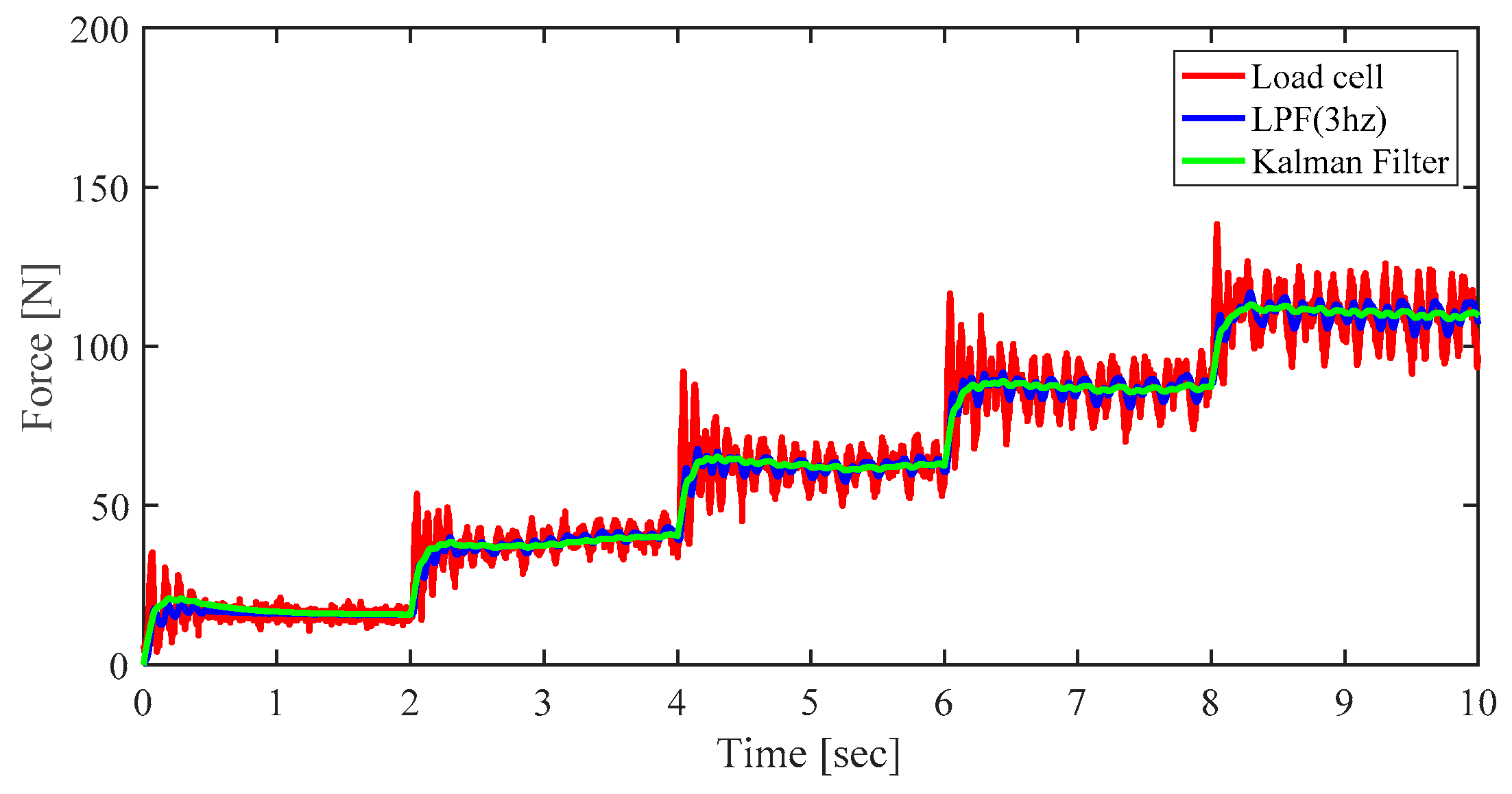
Figure 4 shows the load cell signal, the signal processed by the LPF, and the signal processed by the KF. Unlike LPF, which has a limitation in lowering the cutoff frequency due to the phase delay, the KF further reduced noise.
4. Control Design
In this study, the main purpose was to control the tension robustly and precisely in all sections with constant and varying tension. To achieve this goal, we propose a tension controller design based on a model expression and FF controller with excellent tracking performance in the transient section. Moreover, model uncertainty and external disturbance were compensated for by using the DOB. Finally, robust stability of proposed control system was proved by using the small-gain theorem. The proposed tension control structure is shown in Figure 5 and the unwinder motor was also controlled by the same control structure.
4.1. Tension Controller
In this study, the tension controller was designed using a proportional-integral (PI) controller based on the model expression. The model-based PI controller is widely used in practice because it is simple to apply and easy to analyze in the frequency domain [25]. If the zero of a PI controller is designed to cancel the pole of system, the closed loop response characteristic can be made to be equal to the first order lag element. The equation is written as follow:
where is the input signal, is the nominal plant, is the tension controller, and is the control bandwidth. Therefore, the tension controller has the following form:
As shown in Equation (18), the frequency bandwidth of the controller is given by . Therefore, it is possible to design a controller without overshoot only by determining the frequency bandwidth of the desired controller.
4.2. Feedforward Controller
Unlike the feedback control, which can only react after the error between the reference signal and the measured system state occurs, a FF controller that does not feed back the signal provides excellent tracking performance in the transient section because the response speed is fast. Thus, the FF is used to quickly implement the desired behavior when we know the dynamics model of the control system. It is designed as shown below:
where is the FF controller. Therefore, the FF controller has the form of
Theoretically, to achieve perfect control without any error between the reference signal and the actual system state, the transfer function must be 1. Therefore, the FF controller must have an exact reciprocal relationship with the plant. In this way, the FF controller is simple in design and powerful in performance, but it has the disadvantage that it is impossible to compensate the uncertainty of the model and the external disturbance.
4.3. Disturbance Observer
The DOB is an effective method of robust control to solve external disturbance and model uncertainty, and is widely used in various fields. It is not only excellent in control performance but also convenient to apply because of its simple structure. In particular, by simply adding the DOB to the inner loop of the existing controller, the performance of the outer loop controller can be guaranteed without separately considering the performance degradation due to disturbance and model uncertainty. The DOB estimates the disturbance, and the estimated disturbance signal is used as a disturbance cancellation input. The DOB is composed of an inverse nominal plant and LPF that cuts off the disturbance in the low-frequency region. is expressed as follows:
where is the cutoff frequency. To improve the performance in suppressing disturbance, the cutoff frequency should be increased. However, this is restricted to guarantee robust stability, as more unnecessary frequencies can be passed. Thus, it is critical to design an appropriate cutoff frequency.
The effectiveness of the DOB is clearly explained by transfer functions written as follows:
where is the control input and is the measurement noise.
plays an important role in compensating disturbance and model uncertainty in the DOB. If the input frequency is smaller than the bandwidth of the (i.e., = 1), the first expression is and the second expression is zero. This means that model uncertainty is compensated for and low frequency disturbances are rejected. On the other hand, if the input frequency is higher than the band-width of the (i.e., = 0), the third equation is zero. Therefore, the high-frequency noise is removed.
4.4. Robust Stabilty Analysis of a Closed Loop Control System
In this section, we demonstrate the robust stability of the closed loop control system. The R2R system has model uncertainty because the inertia of the web in roll form changes during the process. To reflect this model variation, the actual plant is expressed as follows:
where is the multiplicative model uncertainty.
In Equation (8), the actual plant can be represented by the following parameters as follows:
Actually, these parameters have confidence intervals, not single values (i.e., confidence interval A = (0.005, 0.0015), B = (0.15, 0.25)) Moreover, the multiplicative model uncertainty is calculated as follows:
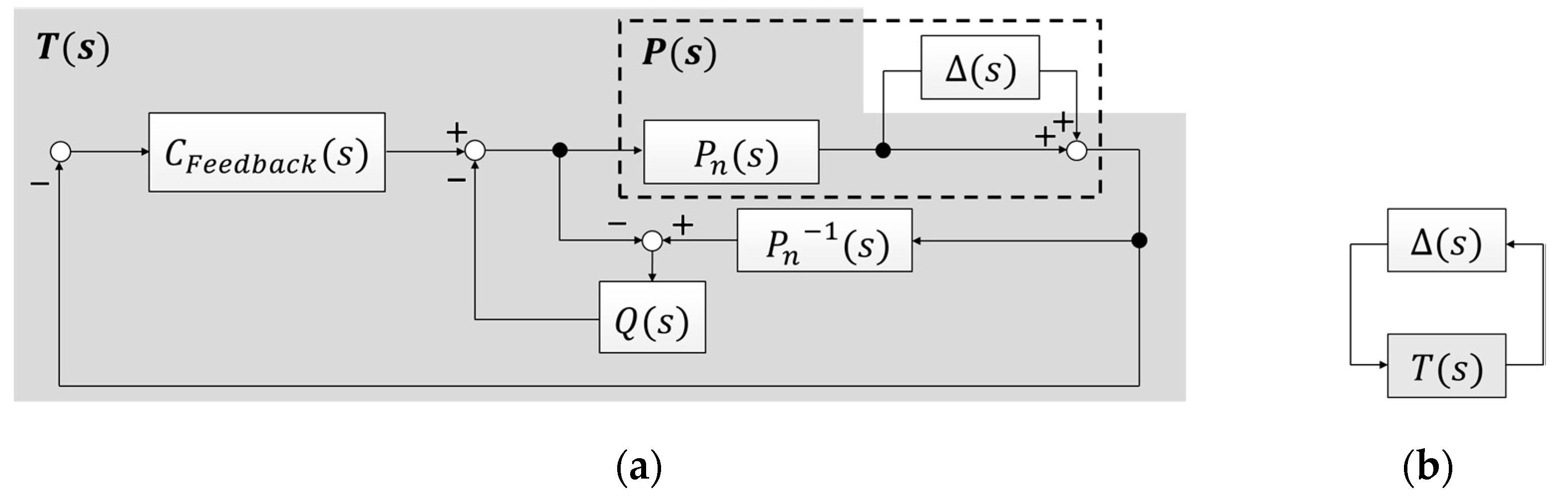
The small-gain theorem was applied to demonstrate the robust stability of the closed loop control system. As shown in Figure 6b, the following conditions are given by the small-gain theorem:
where is the complementary sensitivity function and is expressed as follows:
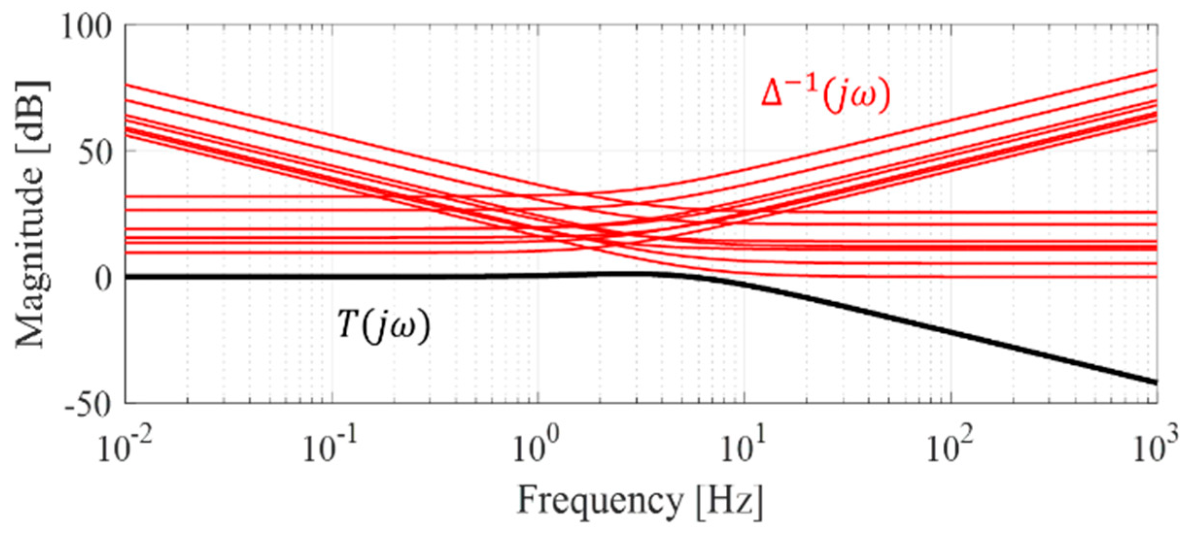
In the bode plot of Figure 7, the magnitude of the complementary sensitivity function is below the magnitude of inverse multiplicative uncertainty. This means it is possible to implement good tracking performance over the whole range of frequencies.
5. Experimental Verification
In this section, we introduce the R2R system used in the experiment and the experimental results of the proposed control scheme.
5.1. Experimental Setup
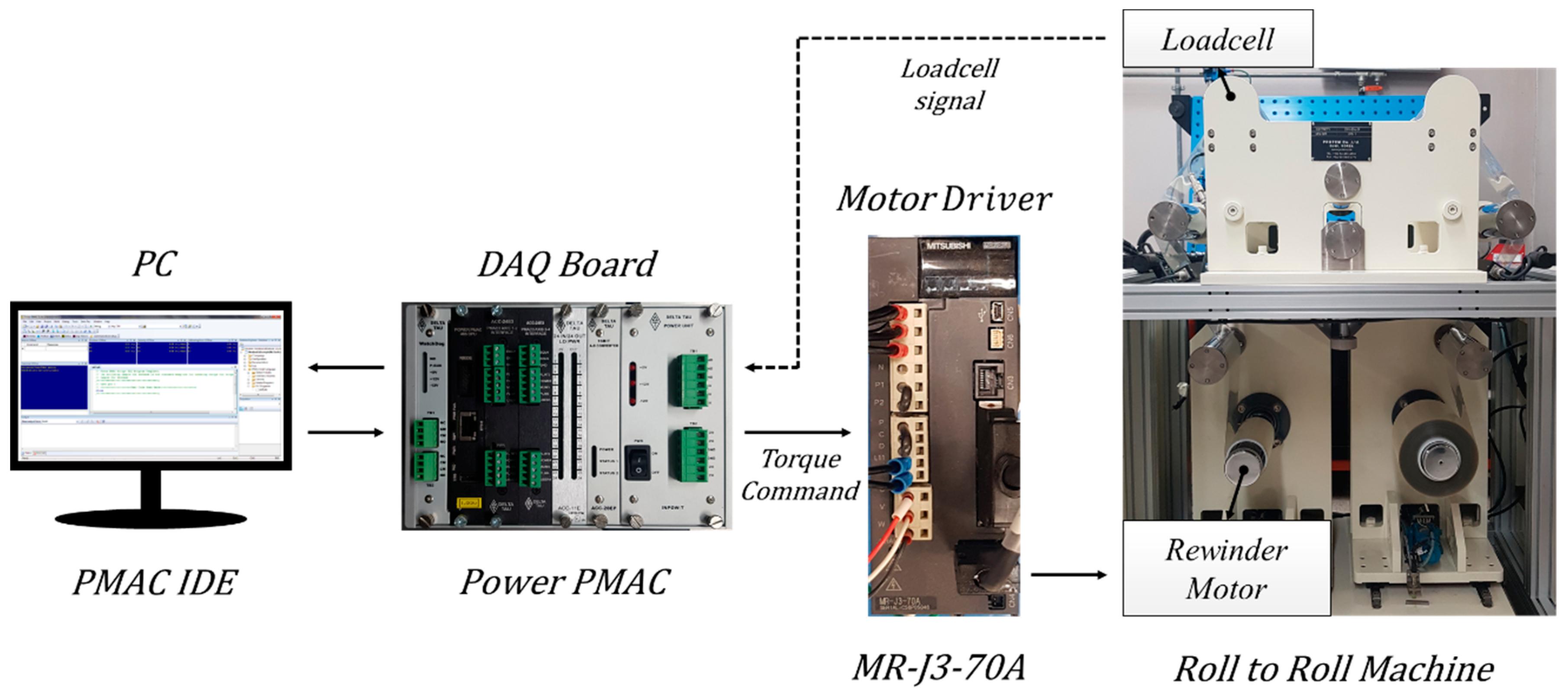
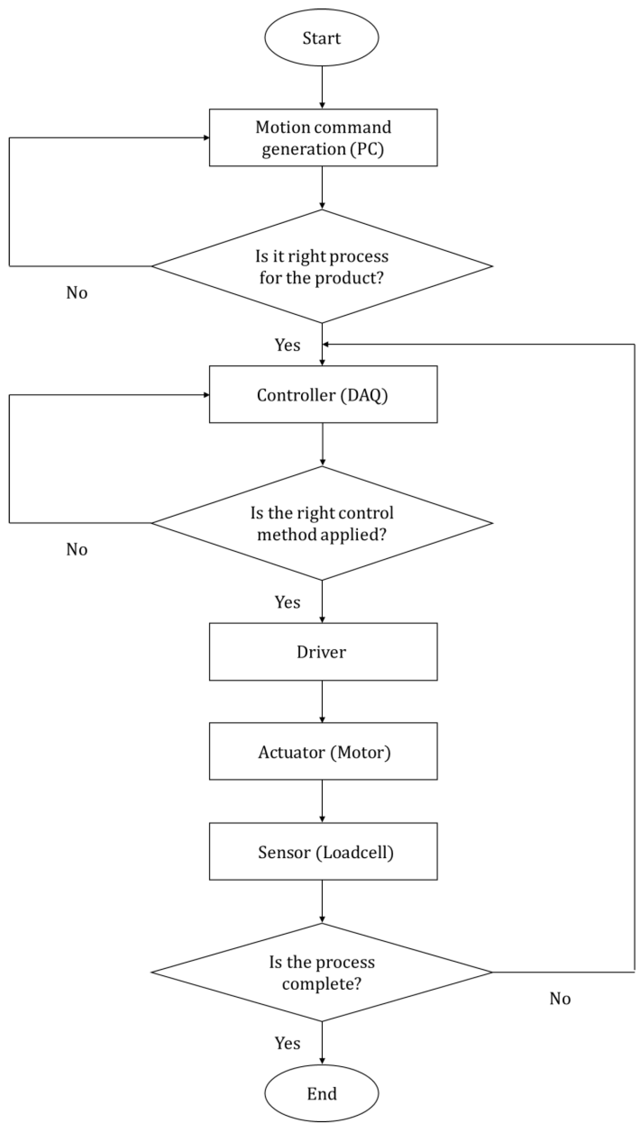
All experiments were conducted on the R2R system depicted in Figure 8 and the procedure was as follows. After fixing the web of the roll form to the rewinder motor, the load cell signal, which varies according to the rewinder motor torque, was controlled in real time by the proposed control algorithm. Then, the opposite ends of the web were fixed to the unwinder motor and the motor was controlled equally. Finally, the feeder motor, which operates only for web feed, was controlled at a constant speed by the proportional-integral controller. A Mitsubishi AC servo motor HF-KP43 and Mitsubishi motor driver MR-J3-70A were driven as rewinder, unwinder, and feeder motors. These were controlled in real time by a Power PMAC ACC 24E3 axis-interface board with 0.1-ms sampling time. The Power PMAC’s Integrated Development Environment (IDE) program includes the GNU compiler; thus, we designed the control algorithm with a C-based user code. Figure 8 and Figure 9 show the overall control system and program flow chart for the R2R system.
5.2. Experimental Results
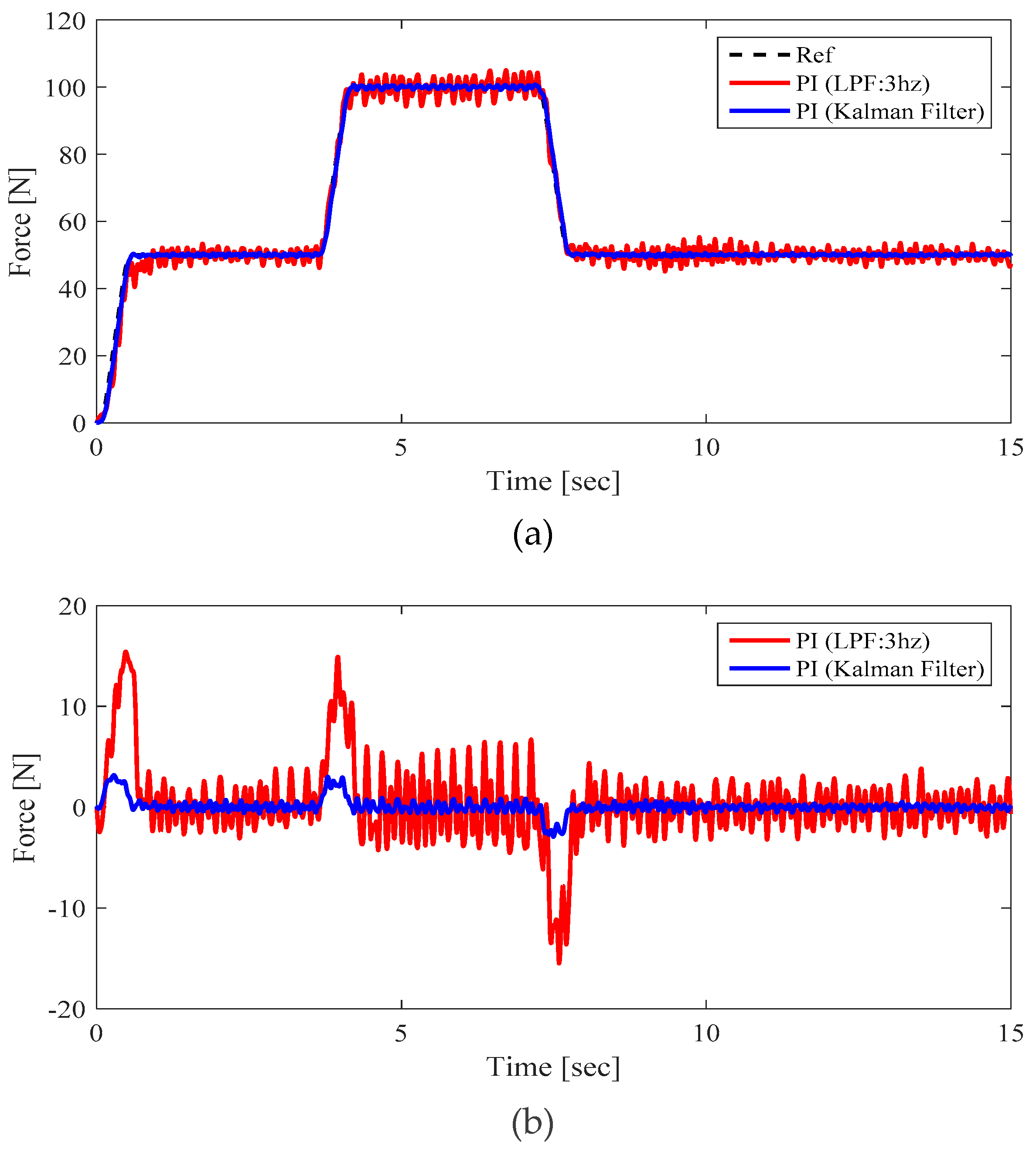
In order to evaluate the tension tracking performance of the proposed control scheme, experiments were carried out under the following conditions. The web was transported at a constant speed by the feeder motor and the tension command had a section varying from 0 N to 100 N. Figure 10 shows the experimental results for verifying the performance of the KF. As shown in Figure 10b, the tracking error could be reduced and the bandwidth could be increased when signal processing was performed with the proposed KF relative to the LPF, which is a conventional signal processing method in R2R systems.
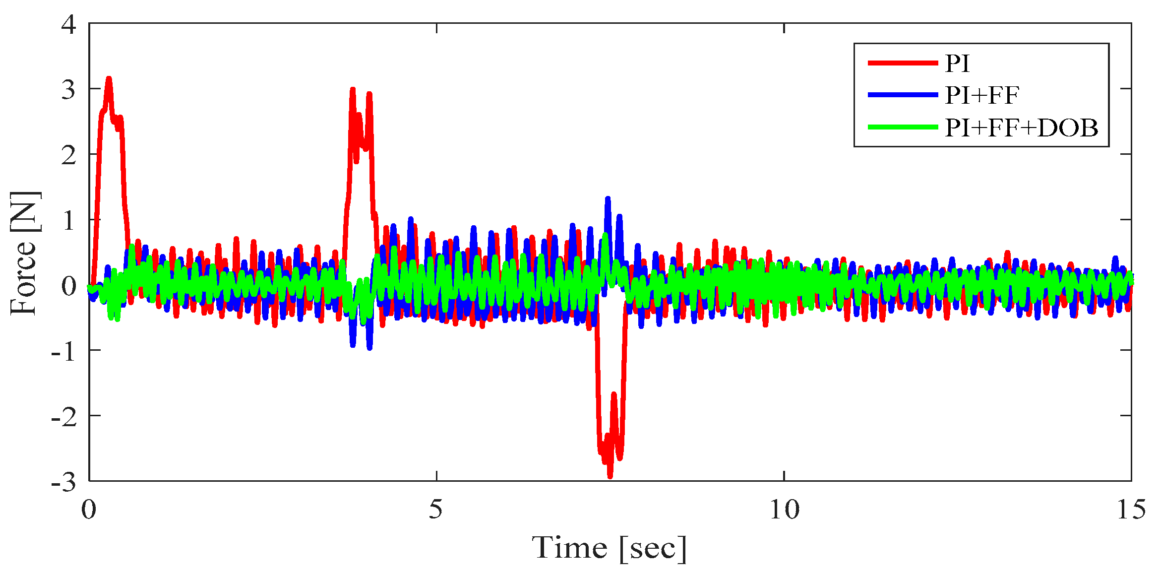
Figure 11 shows the results of applying the proposed control scheme in the case of signal processing with KF. Particularly, the tracking performance of the FF controller was powerful in the transient section where the tension changes. Moreover, the experimental results demonstrate that the DOB is effective in compensating for disturbance and model uncertainty.
6. Conclusions
This paper aims to propose a robust and precise control scheme for a R2R machine to overcome the problems of conventional tension control method. A robust control method such as a DOB is essential in R2R systems with model variation and external disturbance. Therefore, a DOB with PI controller was employed to nominalizes the plant and reject external disturbance. The robust stability of the closed loop control system was proved using the small-gain theorem. Moreover, a FF controller was applied to minimize the tracking error in the transient section. The signal processing of the sensor is very important for precise control in the R2R system. The KF not only reduces sensor noise but also overcomes phase delay problem to improve control performance. Experimental results demonstrate the performance of the proposed control schemes.
Author Contributions
H.H. and J.L. have contributed to this paper, performed the experiments, and proposed R2R control algorithms. K.N. and S.E. contributed effort in conducting the experiment and organizing the manuscript as corresponding authors.
Funding
This work has been supported by the Yeungnam University Research Grant 217A580015.
Conflicts of Interest
The authors declare no conflict of interest.
References
- Søndergaard, R.R.; Hösel, M.; Krebs, F.C. Roll-to-roll fabrication of large area functional organic materials. J. Polym. Sci. B Polym. Phys. 2013, 51, 16–34. [Google Scholar] [CrossRef]
- Ebler, N.A.; Arnason, R.; Michaelis, G.; D’Sa, N. Tension control: Dancer rolls or load cells. IEEE Trans. Ind. Appl. 1993, 29, 727–739. [Google Scholar] [CrossRef]
- Okada, K.; Sakamoto, T. An adaptive fuzzy control for web tension control system. IEEE Trans. Ind. Appl. 1998, 34, 1762–1767. [Google Scholar]
- Koc, H.; Knittle, D.; de Mathelin, M.; Abba, G. Modeling and robust control of winding systems for elastic webs. IEEE Trans. Control Syst. Technol. 2002, 10, 197–208. [Google Scholar] [CrossRef]
- Shin, K.H.; Kwon, S.O. The effect of tension on the lateral dynamics and control of a moving web. IEEE Trans. Ind. Appl. 2007, 43, 403–411. [Google Scholar] [CrossRef]
- Komada, S.; Ishida, M.; Ohnishi, K.; Hori, T. Disturbance observer-based motion control of direct drive motors. IEEE Trans. Energy Convers. 1991, 6, 553–559. [Google Scholar] [CrossRef]
- Sariyildiz, E.; Ohnishi, K. Stability and robustness of disturbance-observer-based motion control systems. IEEE Trans. Ind. Electron. 2015, 62, 414–422. [Google Scholar] [CrossRef]
- Kim, B.K.; Chung, W.K. Advanced disturbance observer design for mechanical positioning systems. IEEE Trans. Ind. Electron. 2003, 50, 1207–1216. [Google Scholar]
- Lee, H.S.; Tomizuka, M. Robust motion controller design for high-accuracy positioning systems. IEEE Trans. Ind. Electron. 1996, 43, 48–55. [Google Scholar]
- Bhattacharyya, S.P.; Chapellat, H.; Keel, L.H. Robust Control: The Parametric Approach; Prentice-Hall: Upper Saddle River, NJ, USA, 1995. [Google Scholar]
- Eum, S.; Lee, J.; Nam, K. Robust tension control of roll to roll winding equipment based on a disturbance observer. In Proceedings of the IECON 2016-42nd Annual Conference, Florence, Italy, 23–26 October 2016; pp. 625–630. [Google Scholar]
- Jamaludin, Z.; van Brussel, H.; Swevers, J. Friction Compensation of an XY Feed Table Using Friction-Model-Based Feedforward and an Inverse-Model-Based Disturbance Observer. IEEE Trans. Ind. Electron. 2009, 56, 3848–3853. [Google Scholar] [CrossRef]
- Shin, K.H.; Kwon, S.O.; Song, S.H. Feedforward control of the lateral position of a moving web using system identification. IEEE Trans. Ind. Appl. 2004, 40, 1637–1643. [Google Scholar] [CrossRef]
- Boerlage, M.; Steinbuch, M.; Lambrechts, P.; van de Wal, M. Model-based feedforward for motion systems. In Proceedings of the 2003 IEEE Conference on Control Applications, Istanbul, Turkey, 25 June 2003; Volume 1, pp. 1158–1163. [Google Scholar]
- Halimic, M.; Balachandran, W. Kalman filter for dynamic weighing system. In Proceedings of the IEEE International Symposium on Industrial Electronics (ISIE), Dubrovnik, Croatia, 10–14 July 1995; Volume 2, pp. 786–791. [Google Scholar]
- Ljung, L. Asymptotic behavior of the extended Kalman filter as a parameter estimator for linear systems. IEEE Trans. Autom. Control 1979, 24, 36–50. [Google Scholar] [CrossRef]
- Girgis, A.A.; Hwanh, T.L.D. Optimal Estimation of Voltage Phasors and Frequency Deviation Using Linear and Non-linear Kalman Filtering: Theory and Limitations. IEEE Trans. Power Appar. Syst. 1984, 103, 2943–2951. [Google Scholar] [CrossRef]
- Dogariu, L.-M.; Ciochină, S.; Paleologu, C.; Benesty, J. A Connection between the Kalman Filter and an Optimized LMS Algorithm for Bilinear Forms. Algorithms 2018, 11, 211. [Google Scholar] [CrossRef]
- Shaik, S.; Popat, J.; Kumar, T.K. Kalman filter based phase delay reduction technique. In Proceedings of the International Conference on Recent Trends in Information Technology (ICRTIT), Chennai, India, 8–9 April 2016. [Google Scholar]
- Lanzon, A.; Petersen, I.R. Stability robustness of a feedback interconnection of systems with negative imaginary frequency response. IEEE Trans. Autom. Control 2008, 53, 1042–1046. [Google Scholar] [CrossRef]
- Nam, K.; Oh, S.; Hori, Y. Robust yaw stability control for electric vehicles based on active steering control. In Proceedings of the IEEE Vehicle Power and Propulsion Conference, Lille, France, 1–3 September 2010; pp. 1–5. [Google Scholar]
- Nam, K.; Fujimoto, H.; Hori, Y. Advanced motion control of electric vehicles based on robust lateral tire force control via active front steering. IEEE/ASME Trans. Mechatronic 2014, 19, 289–299. [Google Scholar] [CrossRef]
- Nguyen, V.G.; Guo, X.; Zhang, C.; Tran, X.K. Parameter Estimation, Robust Controller Design and Performance Analysis for an Electric Power Steering System. Algorithms 2019, 12, 57. [Google Scholar] [CrossRef]
- Sakamoto, T.; Fujino, Y. Modeling and analysis of a web tension control system. In Proceedings of the IEEE International Symposium on Industrial Electronics, Dubrovnik, Croatia, 10–14 July 1995; Volume 1, pp. 358–362. [Google Scholar]
- Chen, P.; He, Z.; Chen, C.; Xu, J. Control Strategy of Speed Servo Systems Based on Deep Reinforcement Learning. Algorithms 2018, 11, 65. [Google Scholar] [CrossRef]
Figure 1.
(a) Schematic of a proposed roll-to-roll (R2R system); (b) Schematic of a rewinder system.
Figure 1.
(a) Schematic of a proposed roll-to-roll (R2R system); (b) Schematic of a rewinder system.

Figure 2.
Experimental results of system identification: (a) Empty film; (b) Half film; (c) Full film.
Figure 2.
Experimental results of system identification: (a) Empty film; (b) Half film; (c) Full film.

Figure 3.
Kalman filter (KF) structure.

Figure 4.
Results of signal processing.

Figure 5.
Structure of the proposed controller for R2R system.

Figure 6.
Block diagram of proposed control system: (a) Block diagram of the closed-loop control system with multiplicative model uncertainty; (b) Equivalent block diagram.
Figure 6.
Block diagram of proposed control system: (a) Block diagram of the closed-loop control system with multiplicative model uncertainty; (b) Equivalent block diagram.

Figure 7.
Frequency magnitude response for small-gain theorem check.

Figure 8.
Overall control system for R2R system.

Figure 9.
Overall program flow chart for R2R system.

Figure 10.
Experimental results to verify the effectiveness of KF: (a) Reference and measured tension; (b) Tracking errors.
Figure 10.
Experimental results to verify the effectiveness of KF: (a) Reference and measured tension; (b) Tracking errors.

Figure 11.
Tracking error for three different control cases.

© 2019 by the authors. Licensee MDPI, Basel, Switzerland. This article is an open access article distributed under the terms and conditions of the Creative Commons Attribution (CC BY) license (http://creativecommons.org/licenses/by/4.0/).
Share and Cite
MDPI and ACS Style
Hwang, H.; Lee, J.; Eum, S.; Nam, K. Kalman-Filter-Based Tension Control Design for Industrial Roll-to-Roll System. Algorithms 2019, 12, 86. https://0-doi-org.brum.beds.ac.uk/10.3390/a12040086
AMA Style
Hwang H, Lee J, Eum S, Nam K. Kalman-Filter-Based Tension Control Design for Industrial Roll-to-Roll System. Algorithms. 2019; 12(4):86. https://0-doi-org.brum.beds.ac.uk/10.3390/a12040086
Chicago/Turabian StyleHwang, Hyeongjin, Jehwon Lee, Sangjune Eum, and Kanghyun Nam. 2019. "Kalman-Filter-Based Tension Control Design for Industrial Roll-to-Roll System" Algorithms 12, no. 4: 86. https://0-doi-org.brum.beds.ac.uk/10.3390/a12040086
Note that from the first issue of 2016, this journal uses article numbers instead of page numbers. See further details here.