Policy-Based Composition and Embedding of Extended Virtual Networks and SFCs for IIoT


Faculty of Computer Science and Mathematics, University of Passau, 94032 Passau, Germany
*
Author to whom correspondence should be addressed.
†
Current address: Innstraße 43, 94032 Passau, Germany.
Algorithms 2020, 13(9), 240; https://0-doi-org.brum.beds.ac.uk/10.3390/a13090240
Submission received: 17 August 2020
/
Revised: 14 September 2020
/
Accepted: 17 September 2020
/
Published: 22 September 2020
(This article belongs to the Special Issue Virtual Network Embedding)
Abstract
:The autonomic composition of Virtual Networks (VNs) and Service Function Chains (SFCs) based on application requirements is significant for complex environments. In this paper, we use graph transformation in order to compose an Extended Virtual Network (EVN) that is based on different requirements, such as locations, low latency, redundancy, and security functions. The EVN can represent physical environment devices and virtual application and network functions. We build a generic Virtual Network Embedding (VNE) framework for transforming an Application Request (AR) to an EVN. Subsequently, we define a set of transformations that reflect preliminary topological, performance, reliability, and security policies. These transformations update the entities and demands of the VN and add SFCs that include the required Virtual Network Functions (VNFs). Additionally, we propose a greedy proactive heuristic for path-independent embedding of the composed SFCs. This heuristic is appropriate for real complex environments, such as industrial networks. Furthermore, we present an Industrail Internet of Things (IIoT) use case that was inspired by Industry 4.0 concepts, in which EVNs for remote asset management are deployed over three levels; manufacturing halls and edge and cloud computing. We also implement the developed methods in Alevin and show exemplary mapping results from our use case. Finally, we evaluate the chain embedding heuristic while using a random topology that is typical for such a use case, and show that it can improve the admission ratio and resource utilization with minimal overhead.
1. Introduction
The traditional legacy networking paradigm of deploying proprietary and hardware-based network functions is not flexible enough to satisfy the emerging and ever-growing application requirements, mainly the security, performance, and resilience requirements of 5G mobile networks and Industry 4.0. This is due to the complexity and high cost of deploying new devices, upgrading devices, and service innovation. Network Function Virtualization (NFV) is a modern technology that decouples the network functions from the hardware. It builds Service Function Chains (SFCs) of Virtual Network Functions (VNFs) in order to provide end-to-end network services to applications. The SFC might include one or more sub-SFCs that define the data flow paths that are based on traffic specifications. NFV leverages virtualization technologies to flexibly deploy complex network functions on-demand in the required locations. The network functions are deployed in the form of virtual machines or containers on standard servers.
The SFC composition problem has already been discussed by researchers without addressing different application- and service provider-driven policies. Such policies might be required, for example, to place certain VNFs in certain locations or to add certain security functions according to the traffic path and application security requirements. From another perspective, solving the SFC composition problem without considering the application functions imposes inconsistency between the composed SFCs and the application requirements. For example, when the application functions are also virtualized, some functions might need to be instantiated over multiple servers for fault tolerance, load balancing, or server capacity constraints. Such a case requires modifications to the composed SFC, for example, by adding a load balancing VNF between the SFC and instances of the application function.
The problem of embedding a SFC is similar to traditional Virtual Network Embedding (VNE) problems. In VNE, the physical network (Substrate Network (SN)) and the Virtual Network (VN) to be embedded (overlay with Virtual Nodes (VNos) and Virtual Links (VLis)) are represented as graphs. VNE algorithms apply optimization and heuristic methods to find the optimal mapping of the VN on the SN with different objective functions, such as admission ratio, embedding costs, path length, or delay. VNE algorithms are needed in NFV to perform the autonomic composition and embedding of SFCs based on the application requirements and service provider policies.
In this paper, we present a preliminary model that combines NFV with the node and link mapping approaches from VNE. This model transforms an abstract Application Request (AR) that defines certain properties of end-nodes, such as type and location/domain, and it might define preliminary security, low latency, and redundancy requirements. The AR is converted while using graph transformation method to an Extended Virtual Network (EVN) that combines the application end-nodes (physical or virtual) with the composed SFCs based on the rules defined by the service provider. The graph transformation sequentially builds the EVN from the AR based on policies that are related to devices’/functions’ types and locations/domains, redundancy, low latency, security-related network functions, and load balancing. The communication services among VNos are realized via VNF requests.
Several Forwarding Graphs (FGs) are possible based on the created VNF request and dependencies among VNFs. We present an approach for creating all possible FGs while using topological sorting. The EVN embedding algorithm first embeds the application VNos and VLis that do not include VNF requests. Subsequently, the SFCs (FGs) are embedded using a greedy proactive heuristic that is independent of the chain and path lengths. The model is supported by a use case, remote asset management, inspired by the principle of smart factory in Industry 4.0 and based on Industrail Internet of Things (IIoT) concepts.
The motivation behind these methods is to enable autonomic virtual networking in complex environments with minimal user intervention and complexity in defining the application requirements. Furthermore, such a set of polices enable the service provider to satisfy several objectives with feasible priorities. A complete combined VNE–NFV framework that considers the topology and properties of the physical network and application requirements is required for service provides to be able to flexibly and seamlessly deploy applications in a complex environment.
The rest of this paper is organized, as follows; Section 2 presents the main existing approaches to SFC composition and embedding and highlights our contribution to the state of art. Section 3 describes our problem, use case, and system model. Section 4 details our VNE methodologies that are related to AR transformation and EVN and chain embedding, and it discusses the algorithmic complexity of these methodologies. Section 5 presents our implementation in Alevin, the composition and mapping results for a representative AR from the use case, and evaluates the chain embedding algorithm with a random topology. Section 6 concludes this paper.
2. Related Work
Traditional VNE [1] and NFV resource allocation problems deal with relatively fixed VNs and SFCs. To the best of our knowledge, there is no approach that combines both resource allocation problems and generates a virtual topology that meets multiple policies. Because the VNE problem has been extensively studied, we focus in this section on SFC composition and embedding. In [2], the authors provide an extensive survey on NFV resource allocation. They highlight the fact that most of the contributions focus on the chain embedding and use linear programming to optimize the solution for a certain objective, such as runtime, end-to-end latency, and deployment cost. However, several researchers studied the SFC composition problem.
The authors in [3] introduce a model that is based on a context-free language to formalize the VNF requests and a heuristic to compose the SFCs. SFC allocation is formulated as an optimization problem with different objectives. The authors highlight the fact that placing SFCs is complex, in particular for different, possibly conflicting, allocation objectives, such as used number of Substrate Nodes (SNos) or latency. An optimal SFC composition approach that is based on integer linear programming is introduced in [4]. The objective is to find SFCs with minimal bandwidth requirements for a predefined VNF request. The evaluation for small VNF requests shows that this solution outperforms the SFC composition heuristic from [3].
In [5], the authors introduce a heuristic coordinated approach, CoordVNF, which tackles the chain composition and embedding problems with the objective of minimizing the bandwidth utilization. The approach uses backtracking in case of an invalid embedding to find a valid solution starting from the last successfully embedded VNF. The authors compare their heuristic to the previous approach from [3]. For the evaluation, they used a randomly generated SN with 50 SNos and 10 VNF requests. Each VNF request has five randomly connected VNFs. The evaluation for small VNF requests shows that the proposed heuristic is slightly faster and that the residual bandwidth capacity after the embedding is similar for both approaches. In [6], an approach, referred to as LightChain, creates a directed acyclic graph for a VNF request and performs topological sorting to generate a single SFC. This SFC is then embedded on the shortest path between source and destination devices based on the assumption that a path of length n can host n VNFs. This means that each SNo can only host a single VNF. If the current path is consumed, another shortest path is calculated for placing the remaining VNFs.
In [7], the authors make a classification of the SFC deployment problems according to the option of sharing VNF instances. An optimization problem and a heuristic solution are presented in order to find the best SFC composition scheme that achieves minimal demand of link resources and improves the VNF instance utilization. The stages of SFC composition, placement, and assignment are combined. For the evaluation, the authors use a random topology and the average link consumption as a metric. In [8], the authors present a solution for placing VNFs in cloud data centers. They focus on the placement of multi-tenant VNFs that are shared among multiple SFCs to achieve an efficient utilization of network resources in contrast to traditional VNF placement strategies.
In [9], a SFC composition framework, called Automatic Composition Toolkit, is introduced. It tries to automatically detect the dependencies and conflicts among the network functions and model their behavior. The authors define topology and processing dependencies, and action and processing conflicts. In [10], the authors present a typical three-stage coordinated optimization model for NFV resource allocation, which considers CAPEX, OPEX, and link costs. Extensive simulations are performed on three typical random network topologies for obtaining a series of optimal solutions. The evaluation metrics are CAPEX and bandwidth and delay costs.
From another perspective, some researchers address the chain embedding problem when considering other objectives, such as resilient allocation of SFCs. In [11], a model for calculating the availability of the SFC is introduced. The authors present Joint Path-VNF backup model that jointly considers path and VNF backup. Furthermore, they use a priority-based algorithm in order to optimize the composition and mapping of SFCs. In this algorithm, VNF dependency is converted to a VNF priority. There might be several FGs generated according to these priorities. Subsequently, the SFC is mapped on the SN based on an optimal FG. The authors use Alevin [12], an open-source VNE framework written in JAVA, with Barabasi–Albert-based random topology. The evaluation metrics are total data rate, acceptance ratio, max availability, VNF cost, and physical node and link cost. In [13], two main resilience strategies are discussed: VLi and VNF resilience. The VLi resilience strategy tries to calculate a disjoint backup path when mapping a target VLi that connects two VNFs. VNF resilience needs at least two different SNos on which the VNF is allocated. The evaluation focuses on the acceptance ratio and embedding cost.
We contribute to the current state of the art in different aspects. First, a policy-based transformation of an abstract AR composes an EVN that includes the physical and virtual application nodes and the VNF requests. Our policies consider preliminary topological, performance, security, and reliability requirements. Second, we integrate location- and domain-awareness into the SFC composition and embedding solutions. These solutions consider dependencies among VNFs, which also reflect the locations and domains. The transformations add security VNFs according to the domains and locations across which the traffic flows. Third, we define a certain use case of these approaches from Industry 4.0 and design the fixed topology that represents it. The last contribution is an embedding heuristic that tries to find a valid solution for the embedding problem while using proactive verification of the path.
To the best of our knowledge, this is the first work that addresses the composition of an EVN that combines the application and SFCs, based on multiple policies, and in the context of industrial environments. We do not yet consider optimizing the composed SFC, for example, for resource requirements, which is the focus of chain composition works. For these reasons, it is not straightforward to compare our composition method with existing works.
3. Problem Description
The addressed problem is an autonomic conversion of user-driven application requirements to provider-driven network requirements. This is done by first defining a simple graph that represents the application end-points and abstract topological, performance, security, and reliability demands. The graph is then stepwise converted to a virtual network that represents the physical devices and application virtual nodes with their connectivity, types, locations, and security domains. The connectivity might be simple links or composite links that are realized by adding chains of network functions that satisfy both application requirements and provider policies, and according to the topologies of the application and physical network. This virtual network is then mapped onto the physical network by first mapping its nodes according to their properties and resource requirements. Subsequently, the simple and composite links are mapped while using the shortest paths.
The composite links with chains of network functions are mapped using a greedy proactive method that checks the remaining length and next available resources of the target path to make placement decisions in advance. This adaptive method spreads or consolidates the functions over the path according to its length. Consolidating network functions on servers saves network bandwidth and reduces the delay, even if the traffic will traverse a long remaining network path after traversing the chain. However, functions that should be placed in different locations/domains cannot be consolidated in one location/domain.
The target use case is remote asset management in industrial environment using three ICT levels: IIoT/factory hall level, edge computing level, and cloud computing level. The used chain mapping method considers the limited resources and dense traffic at the edge computing level. The random topology that was used for evaluating the chain embedding heuristic reflects such a topology.
3.1. Use Case
Industry 4.0 enterprise applications will support the smart factory through data analysis and autonomic decision making. For this purpose, monitoring, analysis, and management functions at different levels of the enterprise are needed. Remote asset management is required when the administrators manage different distant locations to remotely control customizable production, safety, energy consumption, utilization, and security. IIoT enables remote asset monitoring by installing wireless sensors throughout the factory and integrating them via an Internet gateway. The data can be remotely accessed to take further actions in real-time. However, in addition to the application functions in such a scenario, the service provider shall be able to create and deploy the SFC that can satisfy the specific requirements of the industrial enterprise, such as security and resilience of the monitoring traffic and resultant decisions. Virtualization technologies support the reliability and flexibility of the management applications by deploying data acquisition and analysis functions at the edge and central data centers, respectively. In this scenario, the central data center hosts enterprise functions, while the edge data center hosts individual factory functions. This solution enables the seamless transport of data to an analysis environment.
Asset management is the process of tracking the physical assets and making smart decisions based on the gathered data from the assets and environment. Asset management has been listed as one of the five top industrial IIoT use cases by IBM [14]. In asset management, information about assets are actively tracked without any human involvement. Several types of sensors, such as temperature, humidity, pressure, and proximity sensors, are used to gather data that is transferred to edge/cloud computing for making smart decisions.
Three levels of data processing are represented in this use case: factory hall, edge computing, and cloud computing. Furthermore, the factory hall includes an IIoT gateway and several types of devices (such as sensors and cameras) that produce or consume certain rates of data. The use case also represents multiple locations, and each location might include either multiple factory halls and one edge computing center, or a cloud computing center. The edge and cloud computing levels are assumed to host data analysis and decision making functions. Our use case includes three locations with multiple domains that belong to the three mentioned levels, as depicted in Figure 1.
The cloud computing level that is located in a separate location (location 1 here) performs heavy analysis on the gathered data from the manufacturing locations (2 and 3 here). The analysis results are used for making strategical enterprise decisions, for example, related to customized production.
The edge computing level that is located in each manufacturing location (2 and 3) performs light analysis on the gathered data from the factory halls of this location. The analysis results are used to track the locations of assets and employees and environmental data to predict/detect anomalies in real-time, which are mainly related to safety and security. Edge computing can provide local data analysis with accepted latency in order to activate certain actions in real-time using the actuators in the factory hall. These actions are required for cases that cannot be detected by the devices in the factory hall and require data gathering and analysis. For example, detecting physical security breaches by tracking the placement of certain assets. Additionally, because industrial big data are often unstructured, they can be compressed and filtered by the edge computing before sending it to the cloud [15].
In the factory hall level, the IIoT platform allows for easy control and management. The factory halls in locations 2 and 3 might include IIoT hubs, sensors, actuators, cameras, assets with beacons, and employees with Bluetooth low energy bracelets, as shown in Figure 1. The environmental information, such as temperature and pressure, are captured by sensors. There might be also cameras in the factory halls to capture images to make decisions through image processing in the edge. For example, facial recognition of employees as an additional security measure and detecting manufacturing problems that cannot be directly detected by the factory sensors or devices. The locations of assets and employees are assumed to be broadcasted by beacons and bracelets. IIoT hubs receive this information and send it to the edge computing in the same location to be analyzed. The actuators might activate/deactivate certain devices (such as fans) either based on local decisions or edge or cloud decisions.
3.2. System Model
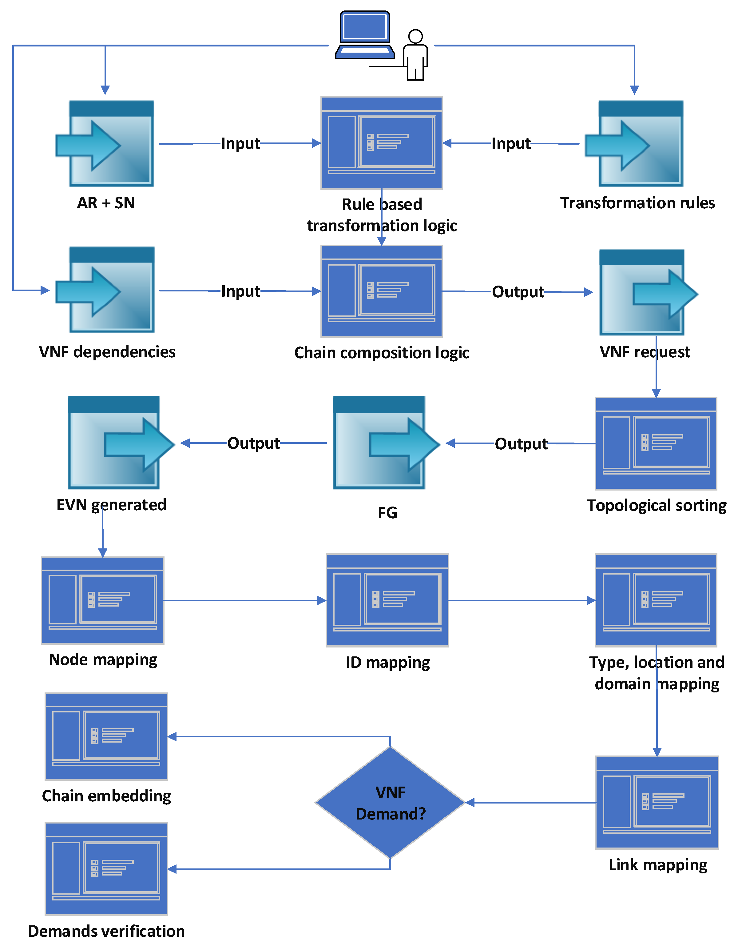
Our main system model (Figure 2) includes a system user who provides the AR and SN definition, the transformation patterns and rules, and VNFs’ dependencies. The AR is an abstraction level that only defines the application entities and its high-level requirements. It is used to avoid involving the application user in the definition of all required details to realize the application from the networking perspective. The AR can be defined as a directed acyclic graph with VNos and VLis , where is the set of nodes and is the set of edges. The demands are represented as and , where and . The properties are also represented as and . We use the same notation for the EVN that results from extending the AR. The SN can be defined as a directed acyclic graph with SNos and Substrate Links (SLis) , where is the set of nodes and is the set of edges. The resources are represented as and , where and . The properties are also represented as and .
The AR is transformed into an EVN that might include additional application VNos, VLis, and a VNF request per VLi, where needed. The VNF request defines the required VNFs and their dependencies that represent a mandatory order of VNFs, such as encryption before decryption. The dependencies are predefined in a general VNF graph that defines all available VNFs and their dependencies.
The proposed approach is based on graph transformation [16] in the network virtualization context. The transformation logic applies certain operations (rules) to generate the EVN from a given AR. The transformation is a formalization of a certain policy that is defined by the service provider. It is composed from a pattern and a set of rules. The pattern is a set of conditions to be checked on the input networks, and the rules are the operations to be applied on network entities that match the pattern. Examples of these operations are adding, deleting, and updating specific VNos, VLis, VNFs, and demands in the AR and intermediate EVNs. We apply one transformation function per pattern in a predefined order of patterns. A transformation function can take the SN, a pattern P, AR, and intermediate EVN as inputs and return the intermediate/final EVN as output.
After the transformation, we use topological sorting to create all possible FGs for each VNF request based on the VNF dependencies. The FG is also modeled as an acyclic directed graph with VNFs , and edges that represent data flow . Usually, multiple FGs are possible, but one FG is selected for each VLi. The embedding logic first maps the application VNos on selected SNos. Subsequently, it maps each VNF request holding VLi using the proactive chain embedding heuristic, and each simple VLi by verifying its demands.
The problem definition is summarized in the following list and Algorithm 1. The transformations, EVN embedding, and FG embedding are detailed in Section 4:
- A physical topology is defined by the service provider.
- The application requirements are defined by the user.
- A set of policies (defined by the service provider), where each policy is composed of:
- –
- A pattern P: conditions on the and for checking and comparison of properties, demands, and resources.
- –
- Transformation T: if P match is found, then perform , where , and T is a set of rules.
- –
- A rule R adds or copies virtual links or nodes, adds or changes the properties or demands, or adds VNFs to the VNF demand of a VLi.
- The policies are applied with the predefined order on the input AR and SN.
- EVN mapping:
- –
- For each VLi in the final EVN, if the VLi has a VNF demand, perform topological sorting on the VNF demand , where the output is a set of FGs.
- –
- Map EVN nodes on the SN based on their properties and demands.
- –
- Map EVN simple VLis based on their properties and demands.
- –
- For each VLi with a VNF demand, map a selected FG while using the chain embedding proactive heuristic.
| Algorithm 1: System Model |
 |
3.3. General Dependency Graph
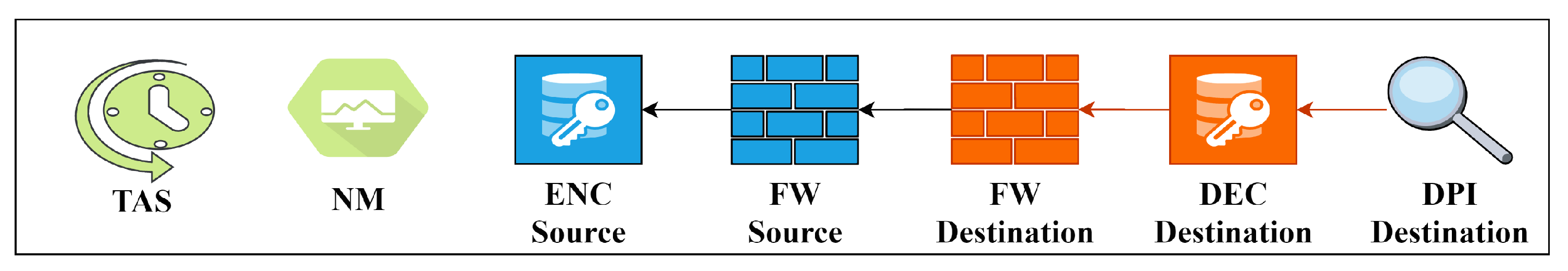
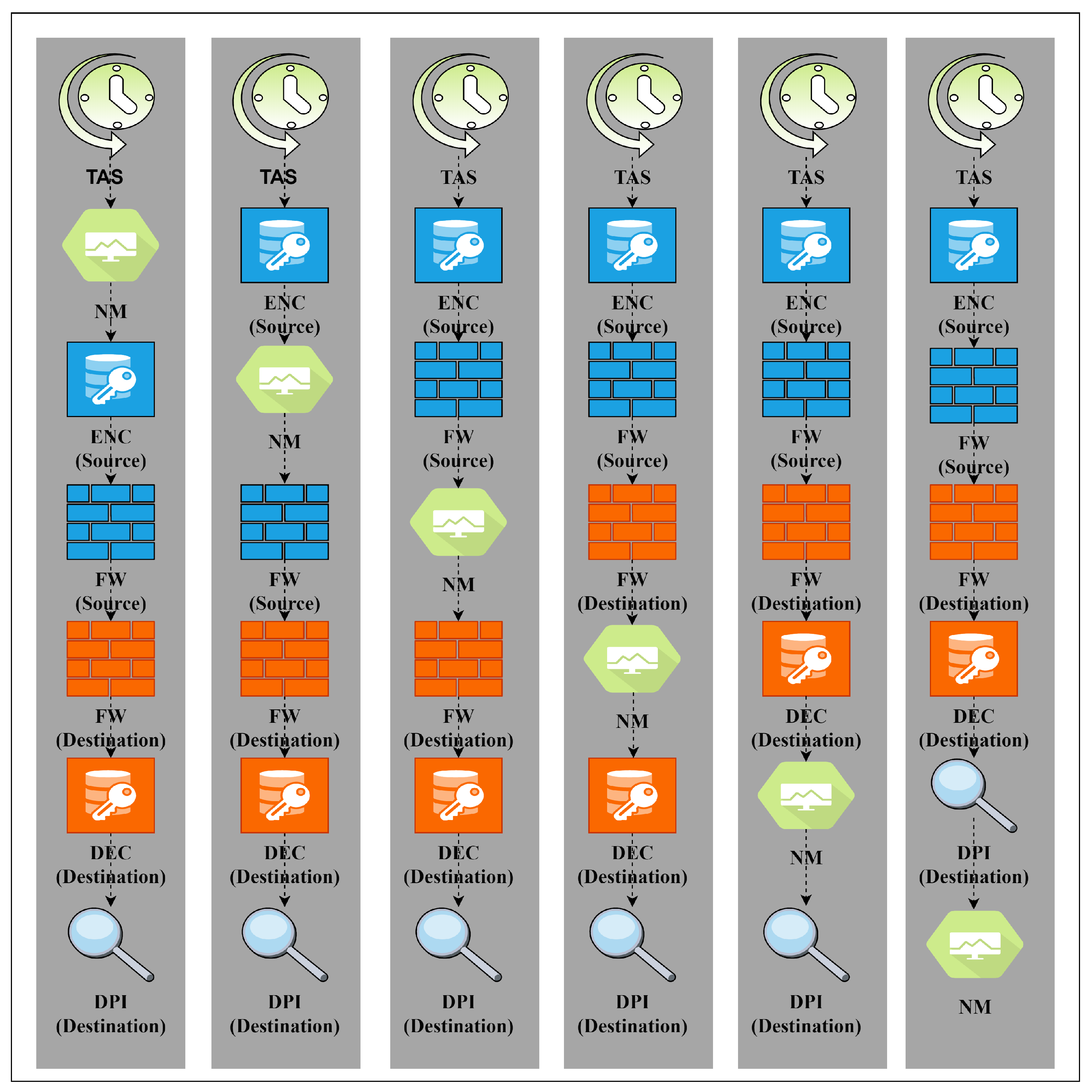
The generic dependency graph includes all possible VNFs, as depicted in Figure 3, where NM = network monitoring, ENC = encryption, DEC = decryption, FW = firewall, and DPI = deep packet inspection. The similar VNFs distinguished by “source” and “destination” represent the placement of the same functions in different domains/locations according to the traffic direction. The transformations add these security functions only for cross-domain SFCs [17]. The arrows show the dependencies between VNFs, which is a transitive relation. For instance, the arrow from the source firewall to the encryption function means that the firewall VNF depends on the encryption VNF and must, therefore, be executed after it. Note here that the dependencies are in the reversed direction from the assumed traffic direction. Furthermore, the network monitoring VNF is assumed to have no dependencies to create a scenario in which several FGs are possible. The Time-aware Shaper (TAS) VNF is a latency reduction function (see Section 4.1.4) without dependency and it shall be allocated on each server hosting the FG. Therefore, the FG composition method only adds it to the beginning of the FG. Figure 4 presents the FGs that are possible from the general dependency graph.
4. Methodology
4.1. Transformations
The following transformations are applied with the same order on the AR and SN. This order reflects a service provider general policy. First, the redundancy policy is only applied to the main VLis in the AR. Second, the target devices are added. Third, the security VNFs are added to cross-location and cross-domain VLis. Fourth, low latency specific VNF is added to the chain if needed. Fifth, the bandwidth is updated for all VLis based on data sources and bandwidth multipliers. Finally, the required load balancing at a destination application VNo is added. For each transformation, the whole SN is checked for the pattern match and a new EVN is created and given to the next transformation.
4.1.1. Redundancy
This transformation copies the VLi when it has redundancy demand. Original and new VLis are both provided with a property “redundant link” that holds an identifier of the redundant link. This is used by the mapping algorithm to find the most disjoint path for the second link from the k shortest paths between the source and destination, found by Dijkstra algorithm. The chain embedding forces the most disjoint paths, even if the VLi holds a VNF demand.
4.1.2. Nodes Types
A single VNo in the AR might represent multiple required devices in the SN. For example, the administrator might need to include all of the sensors from a certain type in a factory hall in an AR, but this is very complex. This transformation adds to the EVN the VNos that represent certain physical devices using the ID demand. The ID demand in VNE and Alevin forces a certain VNo to be mapped on a certain SNo. This is required to create the respective VLi and map it. This transformation is applied on each VNo and the pattern match is checked for each SNo. A new VNo is added to the AR with an ID demand that matches the ID of the compared SNo if the types of both is “device”, and the subtypes, locations, and domains are equal. Subsequently, a VLi between the new VNo and the original VNo is added. The new VNo and VLi are copies of the original to hold the same requirements. However, in our SN definition format, we attach a data resource to all devices with the parameters of cycle time and frame size. These parameters are copied to the matching new VNo to calculate its bandwidth demand by the bandwidth transformation. Here, we assume that each VNo defined in the original AR to represent a physical device has one outgoing edge. When the pattern is checked for all SNos, the original VNo is converted to type “application” and subtype “gateway”. This will force mapping the original SNo that represents a set of devices to a gateway.
After T is applied to all SNos:
4.1.3. Security VNFs
In this transformation, we assume that the service provider defines certain security policies. For example, for a cross-location or cross-domain VLi, a SFC with certain security VNFs must be attached to this VLi. Our exemplary transformation policies presented here consider both cases. For cross-location VLis, encryption, firewall, deep packet inspection, and monitoring VNFs are added to the VNF demand of the VLi. We assume that encryption is not needed for cross-domain VLis (in the same location). Except for the network monitoring function, each type of VNF is attached to the source or destination location/domain. Specific location/domain demands are attached to the added VNFs based on the location/domain demands of the AR. However, the general dependency graph forces the order of these VNFs in the FG. The VNFs in the link FG are assigned the node type “VNF”.
4.1.4. Low Latency VNF
When a VLi in the AR has a low latency demand, a specific type of VNF is added to its VNF demand. This VNF can be executed by a virtual TAS [18] from the IEEE standard on time-sensitive networks. It can reduce the latency of traffic that is processed by servers by scheduling it based on its cycle and load. However, the order of this VNF in the chain is based on the mapping results. This means that it shall be instantiated at each server that is hosts the VNF demand. For this reason, the chain composition algorithm performed after the transformation only adds this VNF to the beginning of the FG. Subsequently, the EVN embedding algorithm maps this VNF on each server as the last VNF from the FG.
4.1.5. Bandwidth
Adding VNos, VLis, and VNFs to the EVN requires the adaptation of the resource requirements. For example, adding a VNo that represents a certain device requires adapting the bandwidth demand of the new and original VLis based on the parameters of the data resource of the device. Subsequently, all of the next VLis shall be updated, including these inside the FG. This approach can be applied to feed-forward VNs, which we use in defining our exemplary ARs.
We consider two types of VNos, VNos that have no incoming edges and intermediate VNos that have incoming edges. For each VNo that has no incoming edges, its produced load per interval, if exists, is used in order to calculate the required bandwidth that is assigned to all of its outgoing edges.
For intermediate VNos that have incoming edges, we sum the required bandwidth of all incoming edges and set it as demanded bandwidth for all outgoing edges. If the VNo has the property of multiplier, then it is considered during the calculation for the outgoing bandwidth demand. In our work we define a specific bandwidth multiplier for each specific VNF type as a property. The default value is 1.
4.1.6. CPU and Load Balancing
After adapting the bandwidth demands, we adapt the CPU demands of the VNos and VNFs while using the CPU factor property, which is used to determine the CPU demand from the incoming bandwidth.
When the resulting CPU demand of a VNo is larger than the minimum CPU capacity of all application SNos (servers) in the same domain, this VNo is copied k times, where k is the ratio of the CPU demand and minimum CPU capacity. The original VNo is converted to type “loadBalancer” and a link between it and each new VNo is created. This is a form of coordination between the EVN composition and embedding stages to avoid the re-transformation of the AR to an EVN as a result of a failed mapping in the embedding stage due to a lack of resources. However, and for simplicity, we currently only apply this to application VNos with incoming edges and no outgoing edges. This exemplary scenario represents a data analyzer that is an application end-node in the AR.
4.2. Creating FGs Using Topological Sorting
In the chain composition stage, the possible FGs are calculated. The authors in [3] introduce a context-free grammar to formalize the request. Topological sorting is a known graph method to sort a directed acyclic graph. This method is used in several works on SFC composition, such as [6] and [19], in order to generate the FG. Our proposed approach is also based on topological sorting, but we calculate all possible FGs. Based on [20], the topological ordering of a graph : for exists, if : . For every non-cyclic graph, a topological ordering exists, and every graph that has a topological ordering is non cyclic.
Using topological sorting for the chain composition enables us to prove whether the VNF request is cycle free and if a possible FG can be calculated. It might happen that the dependencies among VNFs are not defined correctly by the service provider leading to cyclic VNF requests. For example, for a VNF request including encryption and decryption, where both functions depend on each other, no valid chaining is applicable due to the dependency loop. A simplified approach for calculating the topological ordering is to iterate over all VNos and taking a VNo v in each iteration, where and adding it to an array. Afterwards, v and its outgoing edges are removed from the graph. This operation is repeated until there is no VNo left with . If the graph is empty, then a topological ordering exists, otherwise it is not cycle free. The associated pseudo-code, which is based on [20], is presented in Algorithm 2. In the context of chain composition, it is important to calculate all possible sortings for a given graph G. For this purpose, the above mentioned pseudo-code has to be adapted in order to calculate another ordering when the graph has multiple VNos where the . Algorithm 3 represents a pseudo-code for calculating all of the possible sortings for a given graph.
| Algorithm 2: Topological sorting |
 |
The extended Algorithm 3 recursively calculates all possible orderings for a given graph G. The algorithm iterates over all VNos in the graph. For each VNo, if , then it is added to the tentative result and removed with all outgoing edges from the graph. If the graph is not empty, the function is recursively called until all VNos are visited or the graph is empty, then the tentative result is assumed to be a valid ordering and is added to the result.
| Algorithm 3: Finding all topological sortings |
 |
4.3. EVN Embedding
EVN embedding is the combination of VNE and NFV resource allocation and it can be separated in two stages. The first stage is to embed all of the nodes and simple VLis, and the second stage is to embed the VLis with a VNF request. The node mapping first considers the ID demand to map devices (specific VNo on a specific SNo). Subsequently, the type, subtype, location, and domain are considered to map the other nodes. For the nodes of type “application” and subtype “computeInstance”, the CPU demand/resource is considered.
The link mapping uses Eppstein’s algorithm [21] for finding k shortest paths between the source and destination VNos of the VLi. For the simple link mapping (without VNF demand), the candidate paths are verified for the bandwidth demand. For mapping the VLis with VNF demand (VNF request), the candidate paths are given to the chain embedding heuristic. In both cases, the redundant VLi is mapped on another candidate path from the k shortest paths. This path is chosen as the path with the least number of common SNos with the path used for the original VLi. This method provides high reliability, but with accepted resource utilization by finding the most disjoint short path from the shortest path.
4.4. Chain Embedding Heuristic
In [6], the authors assume that each SNo on the path can host one VNF. The algorithm that is presented in [5] is based on backtracking and, in the case of rejection, tries a different combination starting from the last successfully embedded VNo. Finding a path where the number of hops exactly matches or is greater than the number of VNFs might not be possible or efficient for all FGs, in particular with our use case. Our proposed embedding algorithm tries to find a solution independently from the FG or path length. It is assumed that a SNo can host multiple VNFs when the resource capacity allows. Based on this assumption, a path with less hops than the FG can be utilized. On the other hand, for a path longer than the FG, we can try the next hop on the path in case of lack of resources. Algorithm 4 represents the pseudo-code for our proposed algorithm.
As input, a path connecting two VNos embedded onto different SNos and the FG are given. Initially, the algorithm takes the first nodes in the FG and the path. If the target VNF can be allocated on the current SNo, then the algorithm verifies if the number of residual VNFs is smaller or equal to the residual hops on the path. If possible, the algorithm tries to embed multiple VNFs on a target SNo when the residual path length is less than the residual FG length. This is intended to find a valid embedding to avoid backtracking. If available, the next FG’s node and the next hop on the path are verified.
| Algorithm 4: Proactive chain embedding algorithm |
 |
If the verification is successful, then the target SNo is set to the successor of the current one. This proactive verification is intended in this context to prevent setting the target SNo to the next SNo if it might not be able to fulfill the requirements. If the residual FG is shorter than the residual target substrate path, we try a balanced embedding over all SNos on the path to avoid consolidation. However, because the path might include SNos from different domains or can not host the next VNF, it is necessary to verify whether the next SNo is able to provide enough resources and fulfills the domain requirements of the next FG element. In the next step, the algorithm takes the next VNo in the FG and verifies whether a successful allocation is possible. In case of no possible allocation, it tries to verify whether the next SNo on the path can fulfill the requirements and, otherwise, it tries the next SNo until the last SNo is reached. In addition to VNo verification, the links inside FGs are verified against the SLis. When the last VNF is not mapped to the destination SNo on the path, then the outgoing data rate of the last VNF has to be verified over the residual path.
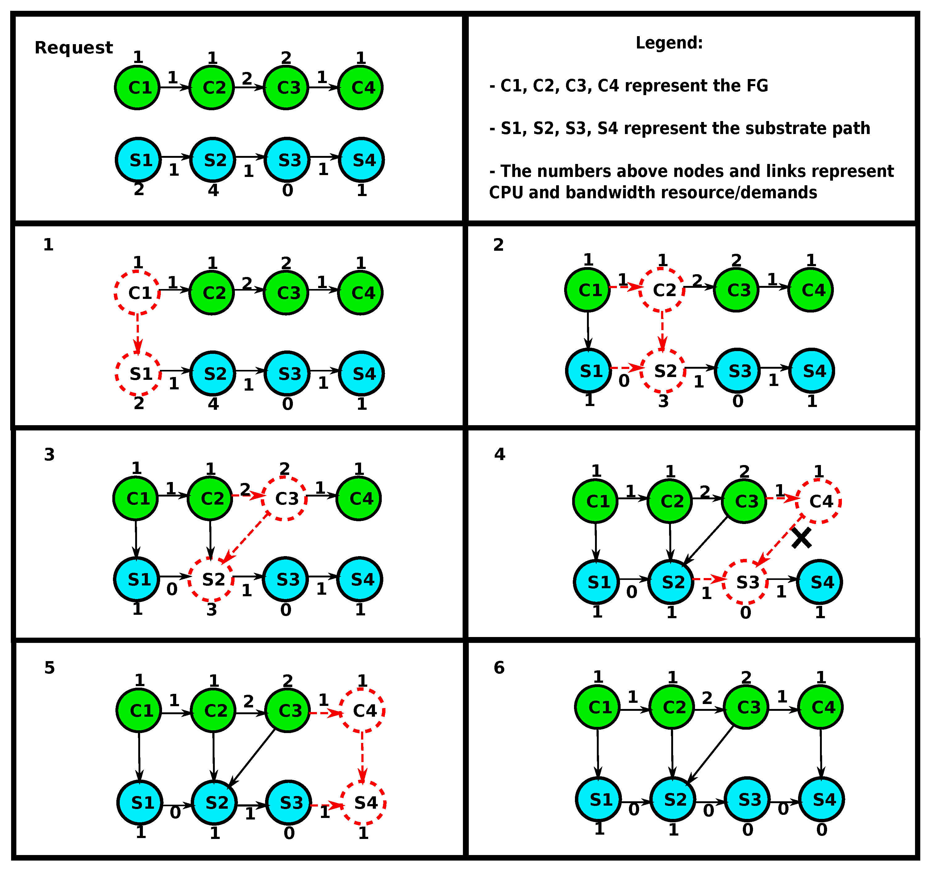
Figure 5 presents an example of the FG embedding. The initial FG contains four VNos (C1, C2, C3, C4) and the target substrate path has four SNos (S1, S2, S3, S4). Resources and demands are assigned to nodes and links in both the FG and substrate path. Nodes and links currently under investigation are dotted. The embedding starts by checking whether C1 can be hosted on S1. Because enough resources are available, the assignment is made here and the new target SNo is set to S2. Again, the algorithm verifies whether C2 can be embedded on S2 and performs the assignment. The target SNo remains S2 since the link bandwidth demand between C2 and C3 cannot be fulfilled on the link between S2 and S3. In the next step, VNo C3 is assigned to S2 and the target SNo is set to S3. Next, the algorithm verifies whether C4 can be hosted on the target SNo S3. In this case, it is not possible, since S3 has no enough CPU resource. Therefore, the algorithm keeps C4 as the target FG VNo and verifies whether the next SNo on the path S4 provides sufficient resources. S4 provides enough resources and the assignment is performed. Because all FG VNos are embedded, the algorithm returns true and terminates. For simplicity, this example considers resource capacities and not domains.
The presented example shows that assuming the same length of the FG and substrate path is not reasonable. It might be required in certain scenarios to embed multiple VNFs on a single SNo in order to find a valid solution. The proposed algorithm performs an embedding while taking link and node constraints into account through forward verification.
4.5. Complexity of the Proposed Methods
We first make the following assumptions to estimate the complexity of the proposed algorithms:
- Neglecting the operations applied by the rule on only a small subset of the EVN entities.
- Considering that the maximum size of the final EVN (nodes M, links L) is known and used to estimate the complexity even for intermediate EVNs.
- (D, D) is the size of the dependency graph. We consider that, in NFV, a function typically has one dependency, so the number of edges in the dependency graph can be approximated to the number of VNFs. The size of the dependency graph is considered the size of each VNF demand.
- We consider that finding one topological sorting of the VNF demand (one FG) is enough, since we do not yet classify the resulting FGs or trying to select the best FG based on a specific criteria.
- P is the diameter of the SN graph (the number of edges in the shortest path between the most distant vertices). We use this worst-case value as the length of the shortest path on which the chain will be embedded.
- We are calculating the complexities in the worst cases without considering locations and domains that might reduce the search space for node and link mapping, in particular, in specific topologies, like in our use case.
We estimate first the complexity of each step in our system model:
- Transformations:
- –
- Redundancy—O(L): checking the redundancy demand of all EVN links and copying them when needed.
- –
- Node types—O(N.M): comparing certain properties of SNos and VNos and adding the required entities to the EVN with their demands.
- –
- Security—O(L): comparing the source and destination locations/domains of the EVN links and adding the required VNFs.
- –
- Low latency—O(L): checking the latency demand of the EVN links and adding the TAS VNF where needed.
- –
- Bandwidth—O(L): checking the bandwidth demand of each VLi and adjusting it based on the bandwidth demands of the incoming edges to its source VNo.
- –
- CPU—O(M): adjusting the CPU demand of all EVN nodes based on the incoming bandwidth, cloning certain nodes, and then adding load balancing function.
- –
- Total complexity of the transformations: O(4L+M (1+N)) = O(L + M.N) when considering that .
- Topological sorting—O(L.D) = O(L): the complexity of finding one topological sorting is O(D+D) = O(D). We assume here that D is small and fixed and that we need to calculate a FG for each VLi.
- Node mapping—O (N.M): finding the SNo with the matching ID, properties, or resources of each VNo.
- Chain embedding—O (2P)=O(P): when mapping a VNF is tried on a SNo, the demands are compared to the resources. A VNF can be mapped on the latest SNo used from the path or any other following node. In the worst case, all path SNos are checked twice for each placed VNF and next VNF that cannot be placed on the same SNo, so a following one is checked. The P value varies with the SN size.
- Link mapping: the complexity of the k-shortest path algorithm is O(E+N.log N)) [21]. This algorithm is used for mapping all VLis. We assume for the worst case that all VLis have VNF demands for which chain embedding will be performed. The total complexity of link mapping is O(L.(E+N.log N+P)).
The total complexity of the solution is: O(L+N.M+L+N.M+L.(E+N.log N+P)) = O(N.M+L(E+N.log N+P)).
5. Results
5.1. Implementation
Alevin [12] is an open-source framework written in JAVA and used to develop, compare, and analyze VNE algorithms. The SN and VN are represented as directed or undirected graphs in which the network entities hold demands and resources that represent either consumable resources or properties, such as ID. In this work, we add type, location, domain, redundancy, latency, and VNF demands and resources. The embedding of each node/link in the VN only succeeds when there are enough resources and matching properties in SN nodes/paths. The Visitor Pattern method is used in Alevin to map demands on the respective resources and occupying (reserving) consumable resources. An extension with NFV support is available for Alevin and developed in [5]. However, we developed our own NFV extension that fits our system model and transformation methods. We added to Alevin a generic structure to define transformations that are based on an abstract transformation class and method that takes the VN and SN as input.
Alevin implements several node and link mapping algorithms, including coordinated node and link mapping. It also implements several evaluation metrics, such as runtime, admission ratio, and cost. However, Alevin is highly flexible for adding new algorithms and metrics. It also provides an evaluation framework, in which different forms of random topologies can be defined with specific parameters. This framework also enables the definition of used mapping algorithms, metrics, and ranges of values for consumable resources and demands. Alevin supports multiple data formats, mainly XML, for representing the SN and VN and mapping the results.
For fixed topologies that represent our use case, we use the easier JSON format to represent the AR, SN, and mapping results. For this purpose, we developed the required parsers that convert the JSON structures to the respective networks, entities, and resources and demands. The AR JSON definition format defines the application end-points and connectors. For each node, an ID, name, type, subtype, location, domain, and, if applicable, CPU demand are defined. For the connector, the source and destination nodes are defined and whether redundancy and low latency are required. The SN JSON definition format is similar but includes resources instead of demands, data resources with cycle and size, and bandwidth resources for SLis. The mapping results are also represented while using a JSON format that shows for each VNo the mapping SNo and for each simple VLi the mapping path. However, for VLis with VNF request, the node and link mappings of the FG are combined. For the FG internal VLis, the source and destination SNos with the types of the source and destination VNFs are shown, even if the source and destination SNos are the same (when multiple VNFs are mapped on one server).
5.2. Applying the Methods to the Use Case
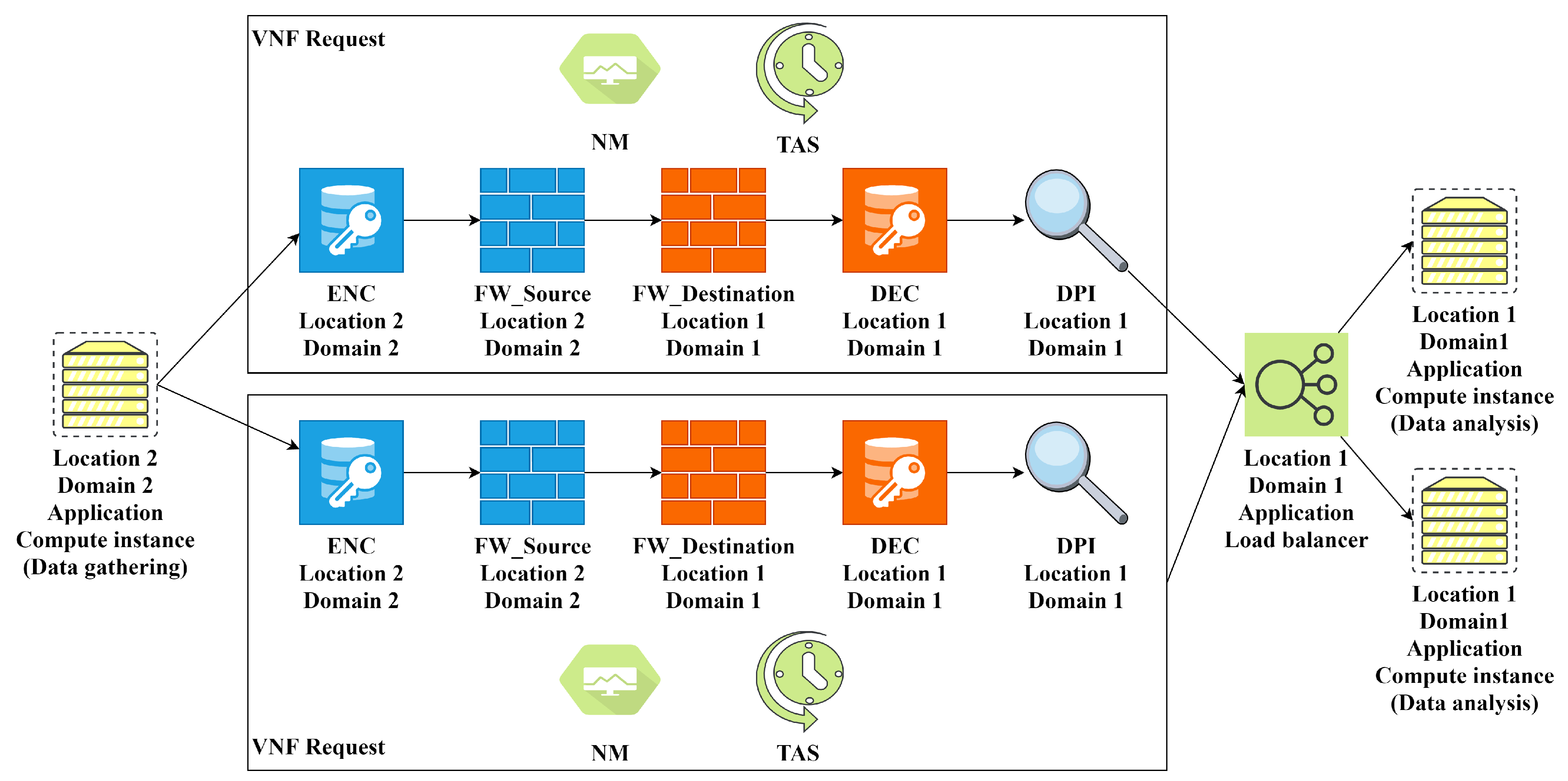
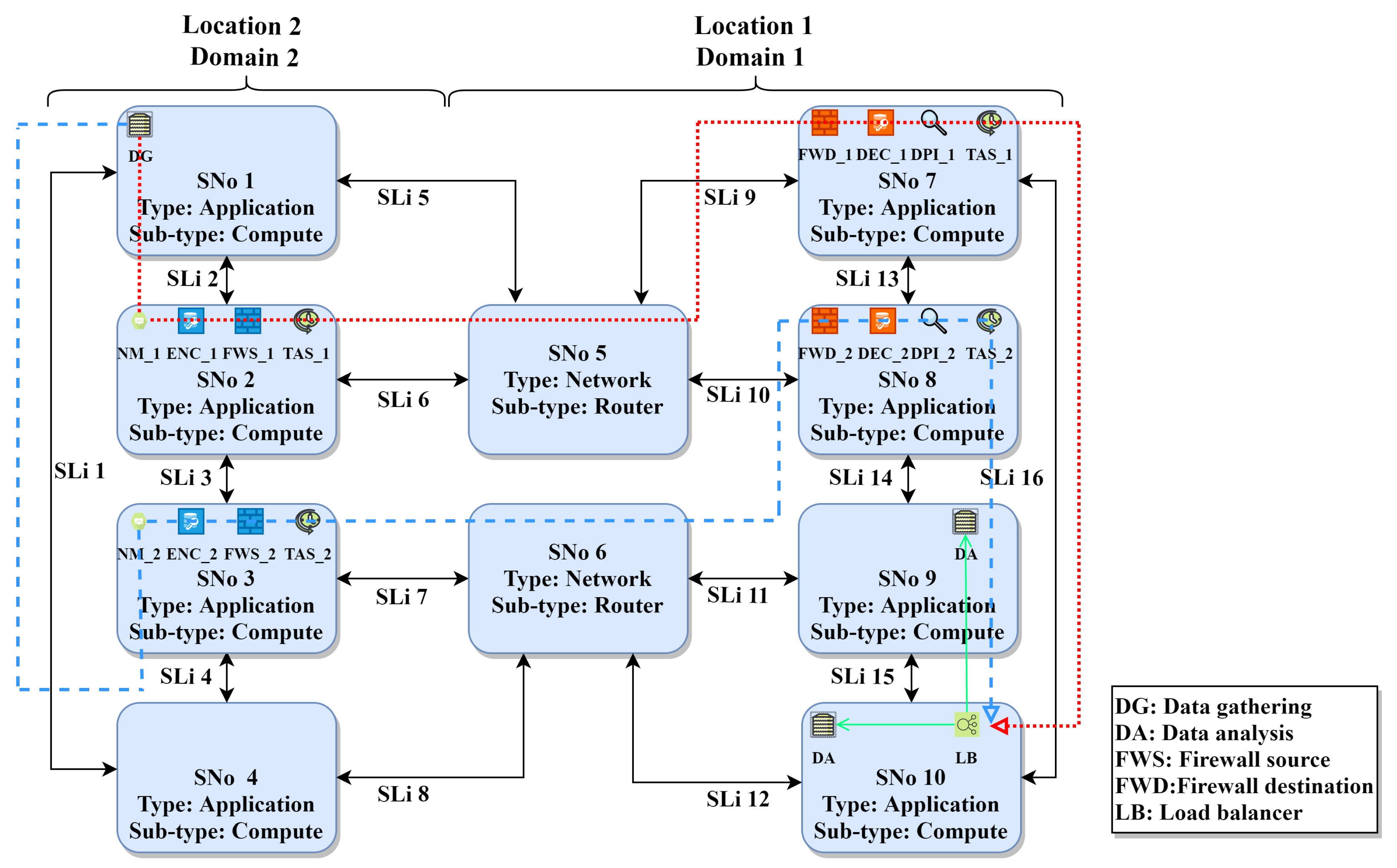
Our fixed topology that represents the use case includes 12 ARs, as shown in Figure 1. These ARs represent the communication between the factory hall level and edge computing level, and communication between the edge computing level and cloud computing level. The ARs in Figure 1 represent AR categories but the real ARs in the definition files include specific end-points, for example, a certain type of sensors. We show in this section the generated EVN for a specific AR (AR11) in Figure 6. We also show the relevant part of our substrate topology defined in Alevin with the mapping results for AR11 in Figure 7.
AR11 connects an application VNo (data gathering) from the edge computing level (location 2 domain 2) to an application VNo (data analysis) from the cloud computing level. AR11 defines redundancy and low latency requirements and connects different locations and domains. For these requirements, two redundant VNF requests are created with encryption, firewall, DPI, and monitoring VNFs. Furthermore, TAS VNF is added. The resulting FGs from the chain composition stage are similar to Figure 4. As mentioned before, TAS VNF is only added to the beginning of the FG and the chain embedding algorithm adds it to each server that hosts the FG. A load balancer is added and the target data analysis VNo is cloned, according to the calculated CPU demand and server capacity. The mapping results in Figure 7 show the mapping of the two redundant FGs over two completely disjoint paths (dotted line for FG1 and dashed line for FG2).
5.3. Evaluation of the Chain Embedding Using a Random Topology
Our chain embedding algorithm is a form of greedy heuristics, since it adapts to the remaining path length and next path resources when making the placement decision. When the path is long, the algorithm tries to spread the VNFs over the path. When the path is short, the algorithm tries to place the VNFs on the least possible number of servers. We compare it to an existing similar solution to preliminarily show its feasibility. Our VNF consolidation method, the random topology, and the distribution of resources are chosen to represent hierarchical edge computing where the resources might be limited and paths are short. Comparison to the results of other works might be challenging, since there are differences in the objectives and topologies.
The evaluation structure in Alevin enables the comparison of different algorithms while using random topologies and several metrics. This structure also enables the definition of the number of runs and the assignment of random resource/demand values from specified ranges. The created SN and VNs, their demands and resources, mapping results, and resulting metrics’ values are exported to an XML file that includes the results for all runs. In the SFC embedding domain, two graph models are used for generating random networks. The Waxman model [22] used in [5], creates highly randomized networks by placing in each step two nodes on a two-dimensional plane and connecting them with a certain probability. This probability is calculated from their distance and two model parameters and , where the large increases the edge density and small increases the probability of shorter edges.
The Barabasi Albert model [23] used in [13] creates random scale-free networks by taking preferential attachment into account. With preferential attachment, the degree distribution follows a power law and the probability of connecting two nodes is based on individual nodes degrees. Initially, a certain number of nodes (), time steps, and edges to be added per time step are defined. Based on the defined number of time steps, a new node with edges is added to the network in each step. A new node is connected to an already existing node i that has a degree with a probability:
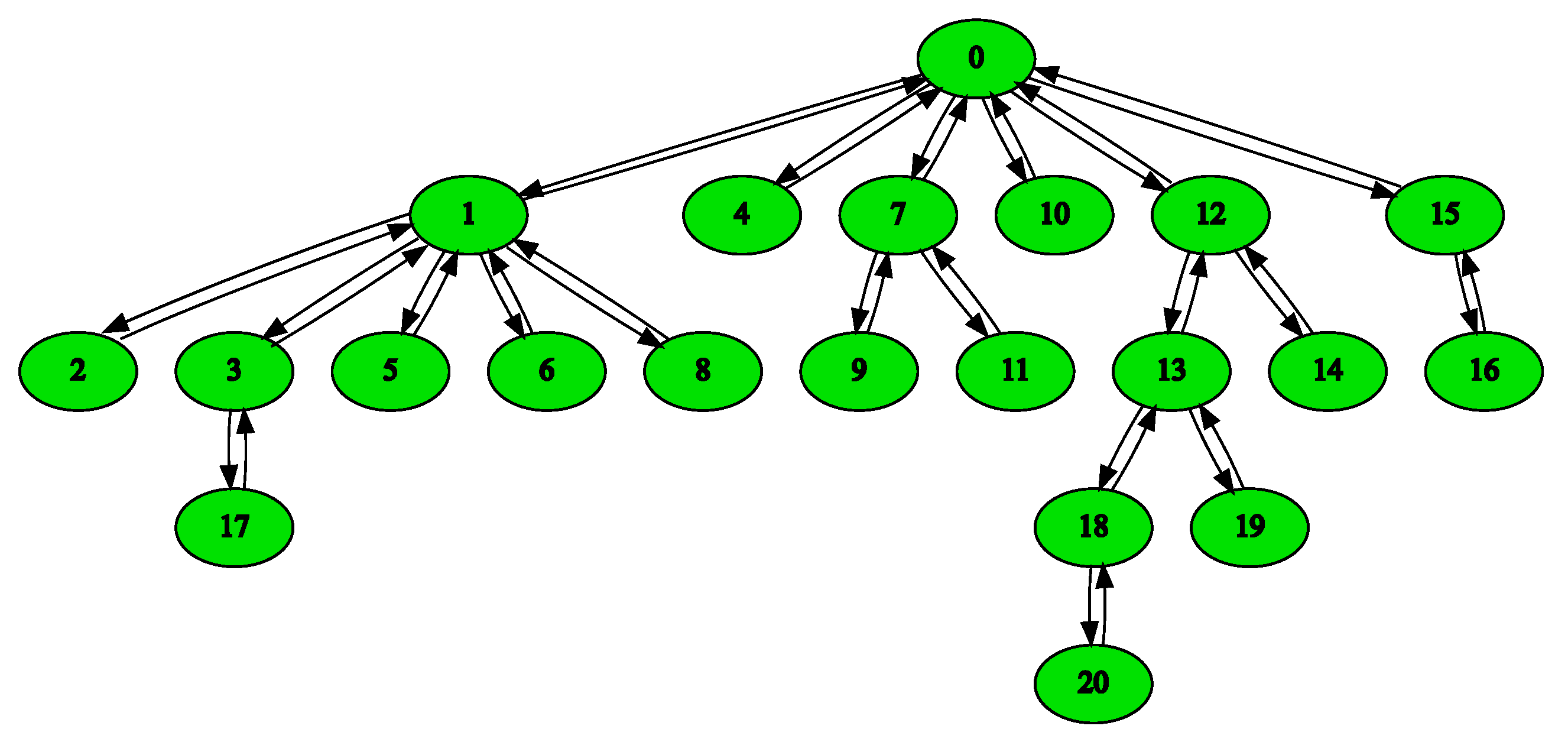
Figure 8 is an exemplary generated topology with the parameters:
- Initial number of nodes: = 1
- Number of time steps: 20
- Number of new edges per time step: 1
Alevin uses directed graphs and the generator adds the reversed edge for each created edge. The Barabasi Albert model is better for representing industrial network levels (as in our use case). We use it for generating the SN for evaluating the chain embedding algorithm. Regarding VNs, each VN has two VNos and a VLi that has a VNF demand, in which we vary the chain length. We adapted our EVN embedding algorithm for this evaluation by just performing node mapping for VNos based on ID demand and using the k-shortest path algorithm to select the path. Subsequently, the chain embedding heuristic is used to map the FG without the locations, domains, and types of nodes. Creating random SN that includes such properties to evaluate the whole system and choosing algorithms to compare with is a challenging future work.
Our system runs in an offline mode, where the SN and EVNs are defined in advance. Each test run is repeated 30 times and the mean values with confidence intervals (0.95%) are graphically depicted. We use two typical metrics from VNE; the runtime and acceptance ratio. The runtime is the time needed by the algorithm to embed a number of EVNs on a SN. The acceptance ratio is the ratio of successfully embedded EVNs to the total number of EVNs in the scenario. We define a new metric to represent the efficiency in utilizing SN resources for chain embedding. Average path utilization is the ratio of SNos that are utilized multiple times to embed the FGs. The metric value is 0 if each VNF from a FG is mapped to a different substrate node:
5.3.1. Runtime
Runtime evaluation is performed for an increased SN size and increased number of EVNs to be embedded. The resource/demand values for these scenarios are adjusted, such that there is no rejection of EVNs. We compare the runtime of the proactive chain embedding to a scenario with the same parameters in which there is no VNF demand and only bandwidth is verified over the path.
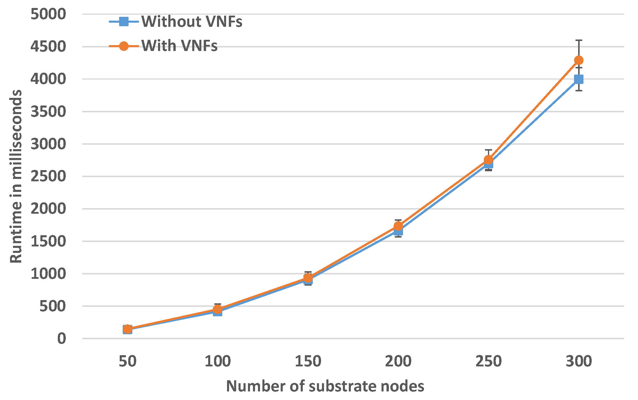
Runtime for Increasing SN Size
In this scenario, the number of EVNs is fixed to 50, where each FG contains four to eight VNFs. The SN size is increased in each simulation to judge how much time it takes to embed a fixed number of EVNs with increasing SN size. The results are presented in Figure 9 and they show a small overhead of the proactive chain embedding, on average 250 ms for medium-size SN of 300 SNos. However the runtime grows with a linearithmic trend. This matches the total complexity of the solution . Linearithmic time complexity is slightly worse than a linear complexity , but much better than a quadratic complexity .
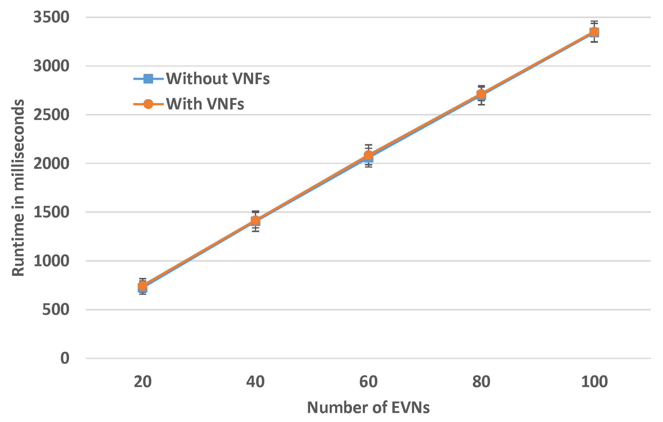
Runtime for Increased Number of EVNs
In this experiment, the SN size is fixed to 200 SNos and the number of EVNs to be embedded is varied. The number of VNFs in each FG is a random number between four and eight. Figure 10 depicts the results for this evaluation. For fixed SN size, the runtime is linear and there is no overhead of chain embedding for this size.
5.3.2. Comparison to LightChain
A simplified version of LightChain from [6] is implemented to compare our proactive chain embedding algorithm to another algorithm. LightChain algorithm tries to allocate the FG on the shortest path between two end-points. If the chosen shortest path is consumed, then the algorithm calculates another shortest path and the remaining VNFs are allocated. LightChain approach does not allow for placing multiple VNFs on a single SNo. Our algorithm can place multiple VNFs that might belong to different SFCs on a single substrate node as long as enough capacity is available. If the selected path cannot be used, then another shortest path is tried. The proactive behavior of the algorithm reduces the probability of path rejection.
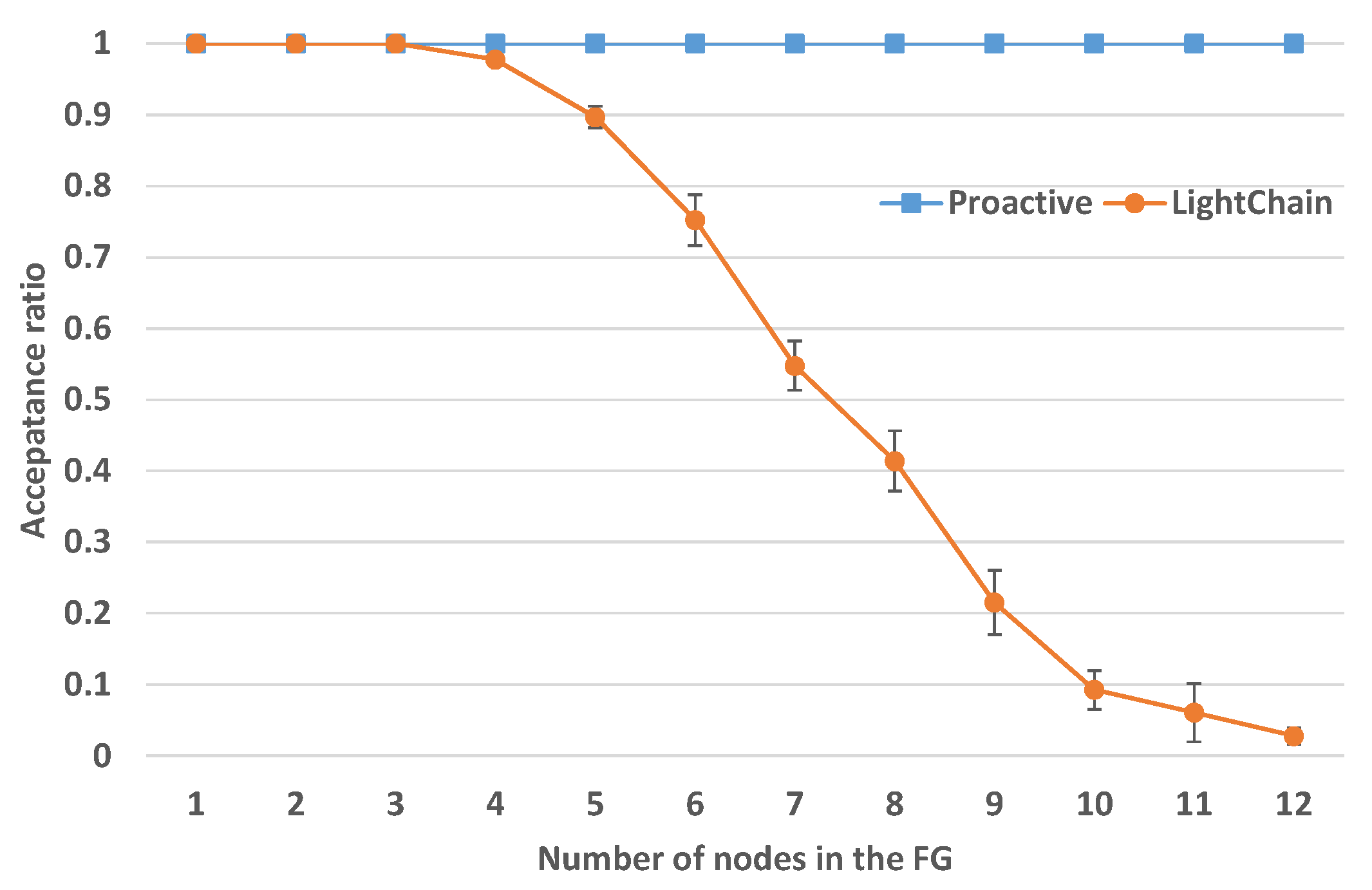
Acceptance Ratio with Increasing FG Length
In this scenario, we evaluate how the acceptance ratio changes when the number of nodes in the FG increases. The SN size is fixed to 100 nodes and 100 EVNs are to be embedded. The FG length varies in the range 1–12. The resources and demands are highly relaxed, such that rejection is not because of resources, but due to the VNF mapping strategy. The results are shown in Figure 11 and they show that the acceptance ratio of the LightChain solution highly decreases with increasing FG length and fixed SN size. These rejections are met when the paths are shorter than the FG. Our chain embedding algorithm keeps a 100% acceptance ratio since it is adaptive to FG length.
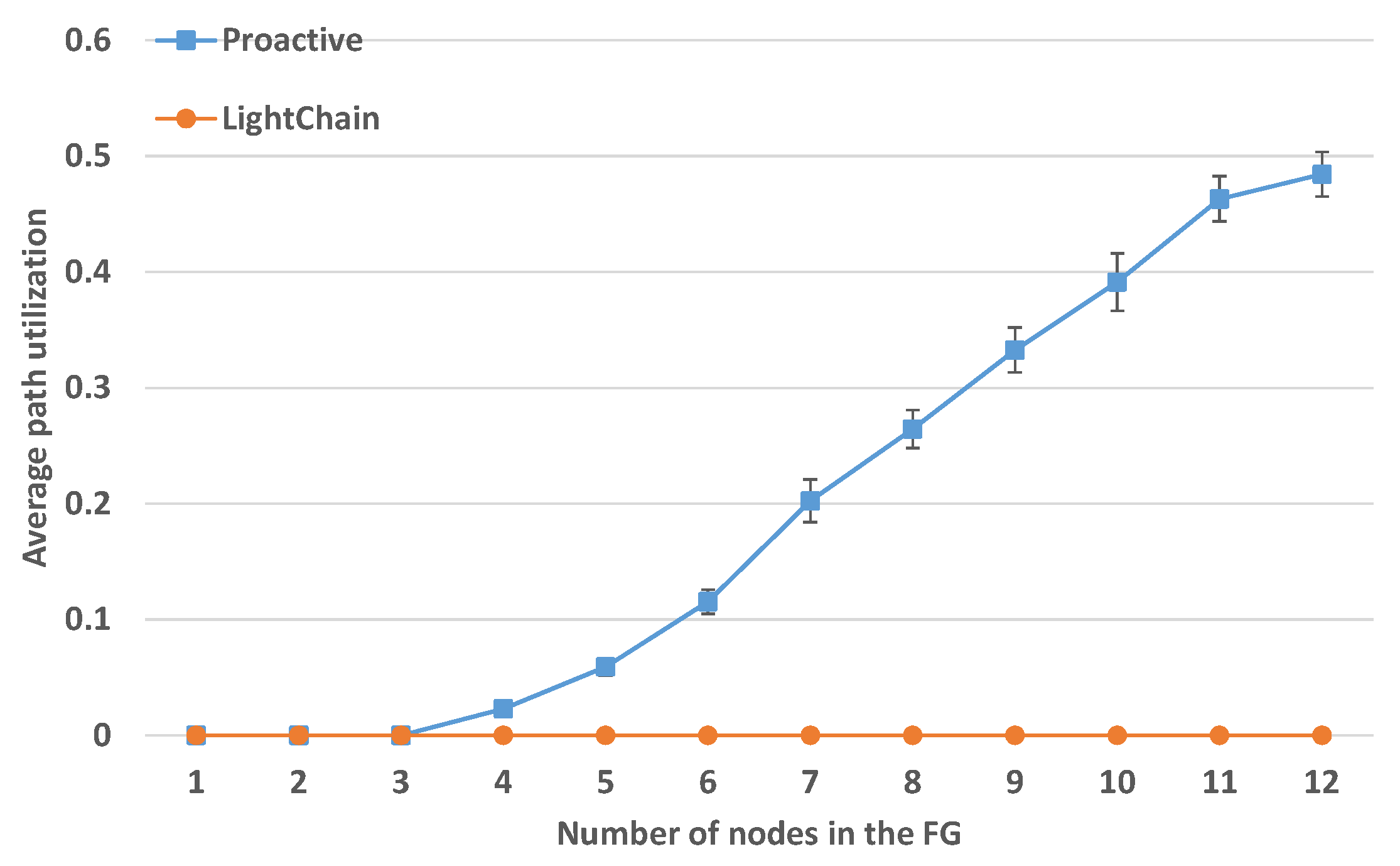
Average Path Utilization with Increasing FG Length
With the same experiment parameters, Figure 12 shows the average path utilization with increasing FG length. The value for the LightChain approach is constantly zero, since the embedding strategy does not allow to place multiple VNFs of a FG on the same SNo. This is different from our proactive approach, where the utilization of SNos increases for longer chains.
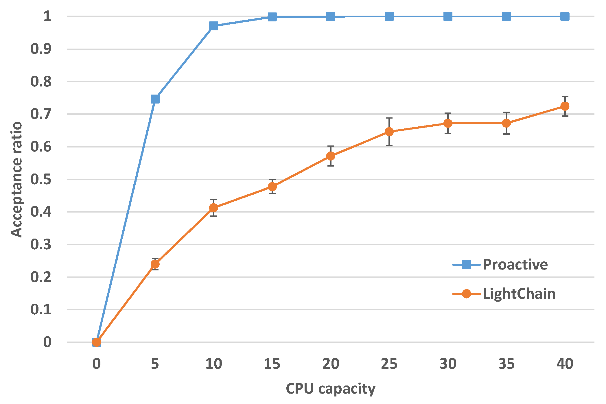
Acceptance Ratio for Increasing CPU Capacity
Comparing the acceptance ratio for scenarios where resources are limited is also important. Therefore, in this scenario, we measure the acceptance ratio with increasing CPU resources, while the bandwidth is highly relaxed. The SN includes 100 SNos and the number of EVNs is 100. Based on the results in Figure 11, when each FG has five nodes, both of the algorithms can reach high acceptance ratio when the resources are highly relaxed. The CPU demand of each VNF is fixed to one. As depicted in Figure 13, the acceptance ratio for the proactive chain embedding approach is rapidly increasing and it reaches 100% acceptance for 15 CPU capacity. For the LightChain approach, the acceptance ratio is also increasing, but at a lower rate. The results clearly depict that occupying multiple SNos on a path results in a much higher acceptance ratio.
6. Discussion
Remote asset management is important for future industries and requires flexible and reliable network services that can be provided by means of network virtualization. However, the underlying network infrastructure imposes several performance, security, and resilience challenges. To address these challenges, NFV that supports flexible composition and deployment of SFCs can be used. However, these NFV procedures shall be automated for large industries based on the application requirements and network service provider policies, such as the location of VNFs and required security mechanisms.
This paper presents a preliminary model that flexibly creates and deploys EVNs and SFCs based on these requirements and policies. The model applies a set of rules sequentially on an AR while using graph transformation. The resulting graph is an EVN that includes the application nodes and the composed SFCs based on its requirements. The paper also proposes a topology-aware and path independent heuristic in order to embed the SFC based on path proactive verification. We implement the developed methods and our use case in Alevin and present an exemplary mapping result. This result shows that our system can correctly compose and map the EVN and SFCs while satisfying all policies. A preliminary evaluation of the chain embedding heuristic, while using a typical random topology, shows that it is promising for such environments in terms of admission, resource utilization, and performance. A main challenge for future work is evaluating the entire approach using random topologies that hold the required properties of entities. Furthermore, determining and implementing comparable solutions from the state of the art is required. Another challenge is more coordination of the stages by SFC recomposition according to the embedding results.
Author Contributions
Conceptualization, W.M. and H.d.M.; methodology, W.M., J.R., and H.d.M.; software, J.R., M.R., and W.M.; Evaluation, J.R., W.M., and M.R.; resources, W.M. and J.R.; writing—original draft preparation, W.M. and J.R.; writing—review and editing, W.M. and H.d.M.; visualization W.M., J.R., and M.R.; supervision, H.d.M. and W.M.; project administration, H.d.M. and W.M.; funding acquisition, H.d.M. and W.M. All authors have read and agreed to the published version of the manuscript.
Funding
This work is supported by the German Federal Ministry for Education and Research (BMBF), under grant agreement no. 16KIS0578, within the project Future Industrial Network Architecture (FIND).
Conflicts of Interest
The authors declare no conflict of interest. The funders had no role in the design of the study; in the collection, analyses, or interpretation of data; in the writing of the manuscript, or in the decision to publish the results.
References
- Fischer, A.; Botero, J.F.; Beck, M.T.; de Meer, H.; Hesselbach, X. Virtual Network Embedding: A Survey. IEEE Commun. Surv. Tutor. 2013, 15, 1888–1906. [Google Scholar] [CrossRef]
- Herrera, J.G.; Botero, J.F. Resource Allocation in NFV: A Comprehensive Survey. IEEE Trans. Netw. Serv. Manag. 2016, 13, 518–532. [Google Scholar] [CrossRef]
- Mehraghdam, S.; Keller, M.; Karl, H. Specifying and placing chains of virtual network functions. In Proceedings of the 2014 IEEE 3rd International Conference on Cloud Networking (CloudNet), Luxembourg, 8–10 October 2014; pp. 7–13. [Google Scholar] [CrossRef] [Green Version]
- Ocampo, A.F.; Gil-Herrera, J.; Isolani, P.H.; Neves, M.C.; Botero, J.F.; Latré, S.; Zambenedetti, L.; Barcellos, M.P.; Gaspary, L.P. Optimal Service Function Chain Composition in Network Functions Virtualization. In Security of Networks and Services in an All-Connected World, Proceedings of the 11th IFIP WG 6.6 International Conference on Autonomous Infrastructure, Management, and Security, AIMS 2017, Zurich, Switzerland, 10–13 July 2017; Springer International Publishing: Cham, Switzerland, 2017; pp. 62–76. [Google Scholar] [CrossRef] [Green Version]
- Beck, M.T.; Botero, J.F. Coordinated Allocation of Service Function Chains. In Proceedings of the 2015 IEEE Global Communications Conference (GLOBECOM), San Diego, CA, USA, 6–10 December 2015; pp. 1–6. [Google Scholar] [CrossRef]
- Hirwe, A.; Kataoka, K. LightChain: A lightweight optimisation of VNF placement for service chaining in NFV. In Proceedings of the 2016 IEEE NetSoft Conference and Workshops (NetSoft), Seoul, Korea, 6–10 June 2016; pp. 33–37. [Google Scholar] [CrossRef]
- Wang, Z.; Zhang, J.; Huang, T.; Liu, Y. Service Function Chain Composition, Placement, and Assignment in Data Centers. IEEE Trans. Netw. Serv. Manag. 2019, 16, 1638–1650. [Google Scholar] [CrossRef]
- Li, D.; Hong, P.; Xue, K.; Pei, J. Virtual Network Function Placement Considering Resource Optimization and SFC Requests in Cloud Datacenter. IEEE Trans. Parallel Distrib. Syst. 2018, 1. [Google Scholar] [CrossRef]
- Wang, Y.; Li, Z.; Xie, G.; Salamatian, K. Enabling automatic composition and verification of service function chain. In Proceedings of the 2017 IEEE/ACM 25th International Symposium on Quality of Service (IWQoS), Vilanova i la Geltru, Spain, 14–16 June 2017; pp. 1–5. [Google Scholar]
- Li, H.; Wang, L.; Wen, X.; Lu, Z.; Ma, L. Constructing Service Function Chain Test Database: An Optimal Modeling Approach for Coordinated Resource Allocation. IEEE Access 2018, 6, 17595–17605. [Google Scholar] [CrossRef]
- Wang, M.; Cheng, B.; Zhao, S.; Li, B.; Feng, W.; Chen, J. Availability-Aware Service Chain Composition and Mapping in NFV-Enabled Networks. In Proceedings of the 2019 IEEE International Conference on Web Services (ICWS), Milan, Italy, 8–13 July 2019; pp. 107–115. [Google Scholar]
- Beck, M.T.; Linnhoff-Popien, C.; Fischer, A.; Kokot, F.; de Meer, H. A simulation framework for Virtual Network Embedding algorithms. In Proceedings of the 2014 16th International Telecommunications Network Strategy and Planning Symposium (Networks), Funchal, Portugal, 17–19 September 2014; pp. 1–6. [Google Scholar] [CrossRef]
- Beck, M.T.; Botero, J.F.; Samelin, K. Resilient allocation of service Function chains. In Proceedings of the 2016 IEEE Conference on Network Function Virtualization and Software Defined Networks (NFV-SDN), Palo Alto, CA, USA, 7–10 November 2016; pp. 128–133. [Google Scholar] [CrossRef]
- 5 Top Industrial IoT Use Cases. 2017. Available online: https://www.ibm.com/blogs/internet-of-things/top-5-industrial-iot-use-cases/ (accessed on 14 September 2020).
- Aazam, M.; Zeadally, S.; Harras, K.A. Deploying fog computing in industrial internet of things and industry 4.0. IEEE Trans. Ind. Inf. 2018, 14, 4674–4682. [Google Scholar] [CrossRef]
- Rozenberg, G. Handbook of Graph Grammars and Computing by Graph Transformation; World Scientific: Singapore, 1997. [Google Scholar]
- Fischer, A.; Kühn, R.; Mandarawi, W.; de Meer, H. Modeling Security Requirements for VNE Algorithms. In Proceedings of the 10th EAI International Conference on Performance Evaluation Methodologies and Tools, Taormina, Italy, 25–28 October 2016; pp. 149–154. [Google Scholar] [CrossRef] [Green Version]
- Mandarawi, W.; Chahed, H.; de Meer, H. A Framework for Virtualizing Time-aware Shaper Using High Performance NFV. In Proceedings of the IEEE 25th International Conference on Emerging Technologies and Factory Automation, ETFA 2020, Vienna, Austria, 8–11 September 2020. [Google Scholar]
- Chen, X.; Zhang, D.; Wang, X.; Zhu, K.; Zhou, H. P4SC: Towards High-Performance Service Function Chain Implementation on the P4-Capable Device. In Proceedings of the 2019 IFIP/IEEE Symposium on Integrated Network and Service Management (IM), Arlington, VA, USA, 8–12 April 2019; pp. 1–9. [Google Scholar]
- Ottmann, T.; Widmayer, P. Algorithmen und Datenstrukturen, 4. Auflage; Spektrum Akademischer Verlag: Berlin/Heidelberg, Germany, 2002. [Google Scholar]
- Eppstein, D. Finding the k shortest paths. SIAM J. Comput. 1998, 28, 652–673. [Google Scholar] [CrossRef] [Green Version]
- Waxman, B.M. Routing of multipoint connections. IEEE J. Sel. Areas Commun. 1988, 6, 1617–1622. [Google Scholar] [CrossRef]
- Albert, R.; Barabási, A.L. Statistical mechanics of complex networks. Rev. Mod. Phys. 2002, 74, 47–97. [Google Scholar] [CrossRef] [Green Version]
Figure 1.
Use Case.

Figure 2.
System model.

Figure 3.
General dependency graph.

Figure 4.
Possible FGs for the general dependency graph.

Figure 5.
Proactive FG embedding example.

Figure 6.
Generated EVN for AR11.

Figure 7.
Embedding AR11 in the substrate network.

Figure 8.
Exemplary random topology generated by Barabasi Albert network generator.

Figure 9.
Runtime for increased SN size.

Figure 10.
Runtime for increased number of EVNs.

Figure 11.
Acceptance ratio for increased FG size.

Figure 12.
Average path utilization for increased FG size.

Figure 13.
Acceptance ratio for increased CPU capacity and FG length of 5.

© 2020 by the authors. Licensee MDPI, Basel, Switzerland. This article is an open access article distributed under the terms and conditions of the Creative Commons Attribution (CC BY) license (http://creativecommons.org/licenses/by/4.0/).
Share and Cite
MDPI and ACS Style
Mandarawi, W.; Rottmeier, J.; Rezaeighale, M.; de Meer, H. Policy-Based Composition and Embedding of Extended Virtual Networks and SFCs for IIoT. Algorithms 2020, 13, 240. https://0-doi-org.brum.beds.ac.uk/10.3390/a13090240
AMA Style
Mandarawi W, Rottmeier J, Rezaeighale M, de Meer H. Policy-Based Composition and Embedding of Extended Virtual Networks and SFCs for IIoT. Algorithms. 2020; 13(9):240. https://0-doi-org.brum.beds.ac.uk/10.3390/a13090240
Chicago/Turabian StyleMandarawi, Waseem, Jürgen Rottmeier, Milad Rezaeighale, and Hermann de Meer. 2020. "Policy-Based Composition and Embedding of Extended Virtual Networks and SFCs for IIoT" Algorithms 13, no. 9: 240. https://0-doi-org.brum.beds.ac.uk/10.3390/a13090240
Note that from the first issue of 2016, this journal uses article numbers instead of page numbers. See further details here.