
An Application of an Unequal-Area Facilities Layout Problem with Fixed-Shape Facilities

Department of Industrial & Management Systems Engineering, West Virginia University, 321 Engineering Sciences Building, Morgantown, WV 26506, USA
*
Author to whom correspondence should be addressed.
Algorithms 2021, 14(11), 306; https://0-doi-org.brum.beds.ac.uk/10.3390/a14110306
Submission received: 19 September 2021
/
Revised: 14 October 2021
/
Accepted: 22 October 2021
/
Published: 23 October 2021
(This article belongs to the Special Issue Metaheuristic Algorithms and Applications)
Abstract
:The unequal-area facility layout problem (UA-FLP) is the problem of locating rectangular facilities on a rectangular floor space such that facilities do not overlap while optimizing some objective. The objective considered in this paper is minimizing the total distance materials travel between facilities. The UA-FLP considered in this paper considers facilities with fixed dimension and was motivated by the investigation of layout options for a production area at the Toyota Motor Manufacturing West Virginia (TMMWV) plant in Buffalo, WV, USA. This paper presents a mathematical model and a genetic algorithm for locating facilities on a continuous plant floor. More specifically, a genetic algorithm, which consists of a boundary search heuristic (BSH), a linear program, and a dual simplex method, is developed for an UA-FLP. To test the performance of the proposed technique, several test problems taken from the literature are used in the analysis. The results show that the proposed heuristic performs well with respect to solution quality and computational time.
1. Introduction
1.1. Motivation of Research
This research was motivated by the investigation of layout options for the machining department within the transmission production area of the Toyota Motor Manufacturing West Virginia (TMMWV) plant in Buffalo (West Virginia, USA). The plant manufactures automobile engines and automatic transmissions for specific Toyota models. TMMWV made modifications to one of its products, which required an investigation of the layout of the machining department within the transmission production area. The layout had a combination of two different types of machines used for machining the older product, called model A and model B machinery. For the production of the newer product, the model A machines will be reused. However, the model B machinery will not be used and will be removed from the layout. Other additional machines used to support production will be removed and replaced. For example, two pieces of equipment used to clean products will be replaced by a single piece of equipment. As a result, this required a re-layout of the machining department which consisted of cells and other pieces of equipment, which are called facilities. Since the facilities are of unequal-area and are rectangular shaped, this problem is defined as the unequal-area facility layout problem (UA-FLP).
The UA-FLP is the problem of locating rectangular facilities on a rectangular floor space such that facilities do not overlap while optimizing some objective. According to Tompkins et al. [1], between 20 and 50% of the total operating expenses within manufacturing is attributed to material handling, and it is generally agreed that effective facilities layout planning can reduce these costs by at least 10 to 30%. Therefore, the most commonly used criterion to determine the efficiency of layouts is the minimization of material handling cost. Material handling cost is the sum of the product of the flow of materials, distance, and transportation cost per unit per distance unit between each pair of facilities. Since the transportation cost is difficult to obtain, this paper considers minimizing the total weighted distance (i.e., the sum of the product of the flow of materials and distance between each pair of facilities).
In the TMMWV plant, the addition and deletion of products as well as the replacement of pieces of equipment caused the existing layout of one of its machining departments to be less efficient with respect to material handling costs. Therefore, the modification of the layout was necessary. Other major factors which may cause the modification of a layout are changes in the product or process design as well as significant changes in the demand of a product. See Francis et al. [2] for a list of factors which may require a re-layout of a manufacturing facility.
1.2. Unequal-Area Facility Layout Problem
As stated earlier, the UA-FLP considered in this paper is defined as the problem of locating rectangular facilities on a rectangular floor space such that facilities do not overlap while minimizing the total distance materials travel between facilities (i.e., minimizing total weighted distance). The rectangular floor space considered is the machining department space within the transmission production area of the TMMWV plant. The facilities are defined as the manufacturing cells, inspection stations, and pieces of equipment used to support production (e.g., washers). The manufacturing cells consist of groups of machines with their material handling systems (e.g., conveyor system). Recall, the model A machines discussed earlier will be reused, and the model B machines will be removed from the existing layout. Since the model B machines form separate cells from the model A machines, the model A-machine cells will remain in the layout, and the model B-machine cells will be removed. In other words, the cells remaining in the machining department will not change (i.e., the internal layout of the cells will not change) and their dimensions are known. Since the dimensions of the cells and other pieces of equipment are known, the facilities have fixed dimensions.
As a result, the assumptions for the UA-FLP considered in this paper are as follows:
- (1)
- Facilities may have unequal-areas and are rectangular in shape.
- (2)
- Floor space available for the facilities is rectangular in shape. Also, it is continuous and constrained (i.e., available floor space has fixed dimensions).
- (3)
- The dimensions of the facilities are fixed and known.
- (4)
- Facilities may have free orientations.
- (5)
- The objective of the UA-FLP is to obtain a layout such that total weighted distance is minimized.
- (6)
- The input and output points of the facilities are at the center of the facilities.
- (7)
- The rectilinear distance measure is used to obtain the distances between the centroids of two facilities.
Note in assumption (2) that the floor space dimensions are fixed (i.e., constrained). Oftentimes this is the case, since most FLPs require re-layout of an already existing department or production area with fixed dimensions (i.e., fixed length and width of layout area), as in the TMMWV layout problem. However, the FLP becomes more complex, since heuristics may oftentimes produce infeasible layouts, especially when the layout area is tightly constrained (i.e., percentage of free space available is low). Many papers in the literature consider an unconstrained rectangular floor space where infeasible layouts are not an issue.
Assumption (3) added with assumption (2) adds even more complexity, since the facility’s dimensions are fixed, and are not allowed to vary as in many of the UA-FLPs in the literature. Therefore, for UA-FLPs with tightly constrained floor space, it becomes extremely difficult to find good feasible solutions. As stated previously, TMMWV wanted to keep the internal layouts of the cells (i.e., some of the facilities). As a result, the dimensions of these cells (facilities) are fixed. Also, they know the dimensions of the additional machines (i.e., other facilities) purchased. It is important to note that fixed facilities dimensions are very uncommon in the UA-FLP literature. Oftentimes, researchers consider fixed area facilities but allow the dimensions of the facilities to vary. In this case, the lengths and widths of the facilities are controlled using special constraints so that facilities are not too narrow.
Assumption (4) states that facilities may have free orientations. That is, facilities may be either horizontally or vertically oriented. If the longer side of the facility is parallel to the x-axis, the facility is considered horizontally oriented, therwise, it is deemed vertically oriented.
1.3. Related Research
Montreuil [3] presented a mixed integer programming (MIP) model for the FLP based on the continuous representation of the floor space, but the areas of the facilities were equal. A similar model was developed by Heragu and Kusiak [4]. However, in this cases the facility areas are unequal with fixed dimensions. Since only small-size problems can be solved optimally using exact methods, heuristic methods were developed to solve the UA-FLP. For reviews of the FLP literature see Kusiak and Heragu [5], Meller and Gau [6], Anjos and Vieira [7], and Perez-Gosende et al. [8].
Based on the assumptions defined above for the proposed problem, there are only a few papers in the literature which consider the UA-FLP with fixed facilities dimensions. For example, Xiao et al. [9] introduced a zone concept to reduce the solution space and used a zone algorithm and simulated annealing algorithm to solve an UA-FLP where input/output points are not restricted to the center of facilities. They can be located within or on the boundary of the facilities. The same problem was considered in Park and Seo [10]. The authors presented a construction algorithm and a median method for the problem. Also, Dunker et al. [11] presented a mixed integer linear program (MILP) and a GA for the UA-FLP where facilities may have one, two, or more input/output points. They decomposed the problem by forming groups of facilities with relatively high flows between them. The layout for each group of facilities is obtained by the GA. After layouts for groups are obtained, rectangles are drawn around facilities in each group, and the arrangement of these rectangles is found. The chromosomes store information on the relative locations of facilities in each group, which is used to fix corresponding binary variables in the MILP formulation, and the corresponding LP is solved to get the layout of facilities on the plant floor. Asl and Wong [12] used a modified particle swarm optimization to solve the UA-FLP. The authors generalized their solution technique to solve the dynamic UA-FLP. Lee and Lee [13] presented a hybrid GA (HGA), which employs both tabu search and simulated annealing, for the UA-FLP. When a population of solutions is obtained in the HGA, which give the order in which facilities are placed on the plant floor, a shape-based block layout (SBL) approach, based on bay structure, is used to place facilities on the plant floor. This produces the layout for each solution obtained from the HGA. Other researchers used the SBL approach for placing facilities on the plant floor. For example, Ingole and Singh [14] used a firefly algorithm and Ingole and Singh [15] used a biogeography-based optimization algorithm to solve the UA-FLP. Allahyari and Azab [16] presented a multi-start simulated annealing algorithm for the UA-FLP, which considered aisle, but the facilities are not orientation-free. Liu et al. [17] presented a particle swarm optimization algorithm for a multi-objective UA-FLP. The objectives of the problem are to minimize material handling cost while maximizing the sum of the total adjacency value and utilization ratio of the plant floor.
A few papers in the literature consider the dynamic UA-FLP with fixed facilities. This is the problem of finding positions of fixed-dimension facilities on the plant floor for a multi-period planning horizon such that facilities do not overlap, and the sum of the material handling and rearrangement costs is minimized. As stated above, Asl and Wong [12] used a modified particle swarm optimization to solve the UA-FLP and generalized their solution technique to solve a dynamic UA-FLP. McKendall and Hakobyan [18] presented a heuristic which consisted of a boundary search heuristic (BSH) with a tabu search (TS) heuristic for the UA-FLP and the dynamic UA-FLP. BSH is used in this paper to construct layouts for the proposed genetic algorithm (GA). Hakobyan and McKendall [19] presented a hybrid heuristic for the dynamic UA-FLP. The hybrid heuristic consisted of a TS heuristic and a dual simplex method. Recall, a dual simplex method is used in the proposed GA.
As stated above, BSH, presented in McKendall and Hakobyan [18], is used to construct solutions (or layouts) for the proposed GA. More specifically, BSH, as a construction algorithm, selects facilities for placement on the plant floor based on the cumulative flow for each facility with all the other facilities. The facilities with higher cumulative flow are placed on the plant floor first. After the first facility, with the largest cumulative flow, is placed on the plant floor, the other facilities are placed along the boundaries of already placed facilities. Welgama and Gibson [20] and Mir and Imam [21] presented similar, but slightly different construction methods. See papers for details.
Besides the metaheuristics mentioned above (i.e., simulated annealing, tabu search, GA, hybrid GA with simulated annealing and/or tabu search, firefly, particle swarm optimization), other metaheuristics have been used to solve UA-FLPs, without fixed facilities dimensions. For example, Kim and Chae [22] used monarch butterfly optimization to solve a UA-FLP which uses a slicing tree structure. Garcia-Hernandez et al. [23] used coral reefs optimization, an evolutionary-type algorithm, to solve a UA-FLP which uses a flexible bay structure. Also, Palomo-Romero et al. [24] presented a parallel GA based on the island model to solve a UA-FLP which uses a flexible bay structure.
Kulturel-Konak and Konak [25] presented a hybrid GA with a linear programming approach to solve a UA-FLP which uses a new encoding scheme, which represents the relative locations (or positions) of the facilities. Once the relative locations of the facilities are set by the GA (i.e., binary variables are set in a mixed integer program), the corresponding linear program is solved to determine the actual layout of the facilities (e.g., shapes and locations of the facilities on the plant floor are obtained). Gonçalves and Resende [26] presented a biased-random-key GA (BRKGA) for a UA-FLP where the facilities dimensions are not fixed. First, the BRKGA is used to determine the order facilities are placed on the plant floor and the dimensions of the facilities. Second, a novel placement strategy is used to place the facilities on the plant floor. Third, a linear programming model is used to improve the solutions (i.e., layouts).
1.4. Contribution and Organization of Paper
Our contribution is the application of the UA-FLP with fixed facilities dimensions to a layout problem encountered at the Toyota Motor Manufacturing West Virginia (TMMWV) plant in Buffalo, WV. Also, an effective matheuristic is presented for the proposed problem which consists of a simple, but effective GA, which is able to produce high quality alternative layouts. More specifically, a GA is used to generate a population of solutions (i.e., permutations of facilities) to determine the order in which facilities should be placed on the plant floor. Next, a boundary search heuristic (BSH), available in the literature, is used to place the facilities on the plant floor to obtain the actual layouts and the fitness of each layout (i.e., total weighted distance). Last, the layouts obtained are used to set the binary variables in a mixed integer linear program, and a dual simplex method is used to solve the corresponding linear program efficiently.
The remainder of the paper is organized as follows. In Section 2, a mathematical programming formulation is presented for the proposed UA-FLP, and a small problem instance is solved using the mixed integer linear programming (MILP) model. The proposed GA is presented in Section 3. In Section 4, some computational results of the proposed techniques on several test problems are given. Finally, Section 5 provides conclusions.
2. Mathematical Model
2.1. Mixed Integer Linear Programming Formulation
The indices, parameters, and variables for the UA-FLP are defined as follows:
- Indices:
- i, j = 1, …, N where N is the number of facilities.
- Parameters:
- fij = fij + fji = units of materials which flow between facility i and facility j (consider only upper triangular matrix)
- ai = shorter side length of facility i
- bi = longer side length of facility i
- L = length of the plant floor space available for layout
- W = width of the plant floor space available for layout
- Variables:
- (xi, yi) = the centroid (or location) of facility i
- li, wi = the length and width of facility i
- dxij, dyij = horizontal and vertical distance between the centers of facilities i and j
- oi = 1 if facility i is vertically oriented and zero otherwise
- leftij = 1 if facility i is to the left of facility j and zero otherwise
- belowij = 1 if facility i is below facility j and zero otherwise
Next, a mixed integer linear programming (MILP) formulation is presented for the UA-FLP:
subject to:
xi ≥ 0.5li Ɐi
xi ≤ L − 0.5li Ɐi
yi ≥ 0.5wi Ɐi
yi ≤ W − 0.5wi Ɐi
xi + 0.5li − xj − 0.5lj ≤ L (1 − leftij) Ɐi, j ≠ i
yi + 0.5wi − yj − 0.5wj ≤ W (1 − belowij) Ɐi, j ≠ i
leftij + leftji + belowij + belowji = 1 Ɐi, j ≠ i
li = aioi + bi (1 − oi) Ɐi
wi = bioi + ai (1 − oi) Ɐi
dxij ≥ xi − xj Ɐi, j > i
dxij ≥ xj − xi Ɐi, j > i
dyij ≥ yi − yj Ɐi, j > i
dyij ≥ yj − yi Ɐi, j > i
xi, yi, li, wi, dxij, dyij ≥ 0 Ɐi, j ≠ i
oi, leftij, belowij = 0 or 1 Ɐi, j ≠ i
Objective function (1) minimizes the sum of the weighted distances. Constraints (2)–(5) ensure that the facilities are within the boundary (area) of the plant floor space available for layout. Constraints (6)–(8) are used to ensure that facilities do not overlap. Constraints (9) and (10) control the orientation of the facilities. For example, if facility i is horizontally (vertically) oriented, set oi = 0 (oi = 1). If oi is not set to 0 or 1, the model will determine the orientation of facility i such that total weighted distance is minimized. Constraints (11)–(14) are used to obtain the rectilinear distances between the centers of facilities. Last, the restrictions on the variables are given in Constraints (15) and (16). Since the MILP model presented above can only be used to solve small-size problems in reasonable time, a heuristic technique is presented next for the UA-FLP, but first a small problem instance is solved using the model.
2.2. Small Problem Instance
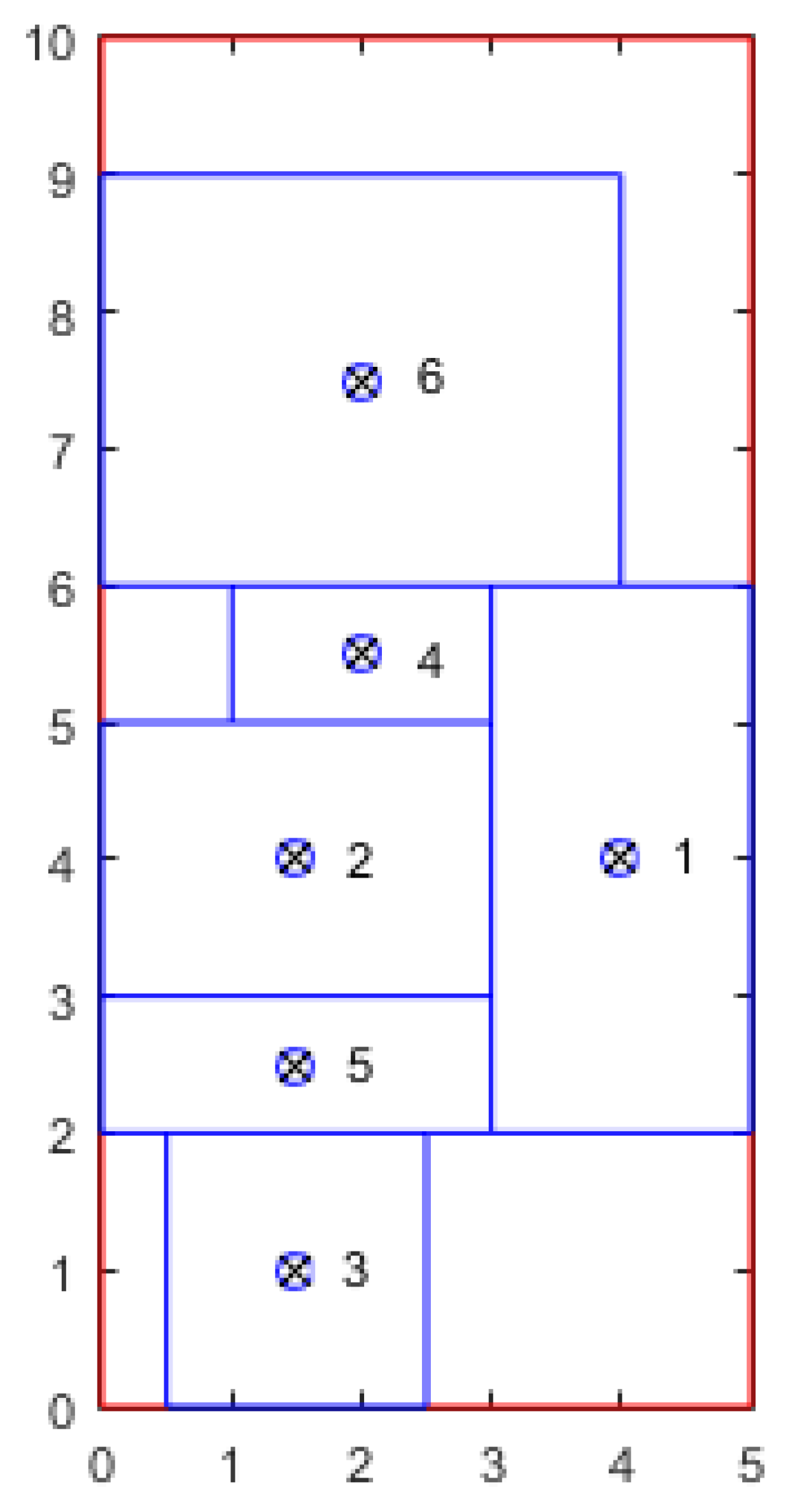
The MILP model for the UA-FLP will be used to solve a small problem instance taken from Xiao et al. [9]. The data for the problem instance is given in Table 1. For instance, the length and width of facility 4 is 1 and 2 distance units, respectively. Also, there are 40 units of materials flowing from facility 2 to facility 3. Recall, to prepare fij for the MILP model, we obtain new fij = fij + fji. The MILP model is solved optimally using the CPLEX solver (version 12.4). The optimal solution is given in Table 2. For example, the center of facility 1 is located at point (4,4) on the plant floor and its length and width is 2 and 4 distance units, respectively. Notice facility 1 is vertically oriented since o1 = 1 and the width of the facility is greater than its length. Recall, that to be vertically oriented means the longer side of the facility is parallel to the y-axis. Also, all the other facilities are horizontally oriented. See the actual layout of the plant floor in Figure 1 where the total weighted distance (i.e., the total distance materials travel) is 1842.5 distance units. The optimal solution was obtained in 1.25 s using the CPLEX solver on Microsoft Windows 10 running on an Intel Core processor with a CPU speed of 3.20 GHz equipped with 16 GB of RAM. Although the small problem instance with six facilities was solved optimally in 1.25 s, it took 21.3 h to solve a problem instance with eight facilities, which will be discussed later. Since the UA-FLP at the TMMWV plant required solving a 20-facility problem, a genetic algorithm is developed for the problem.
3. A Genetic Algorithm (GA) for the UA-FLP
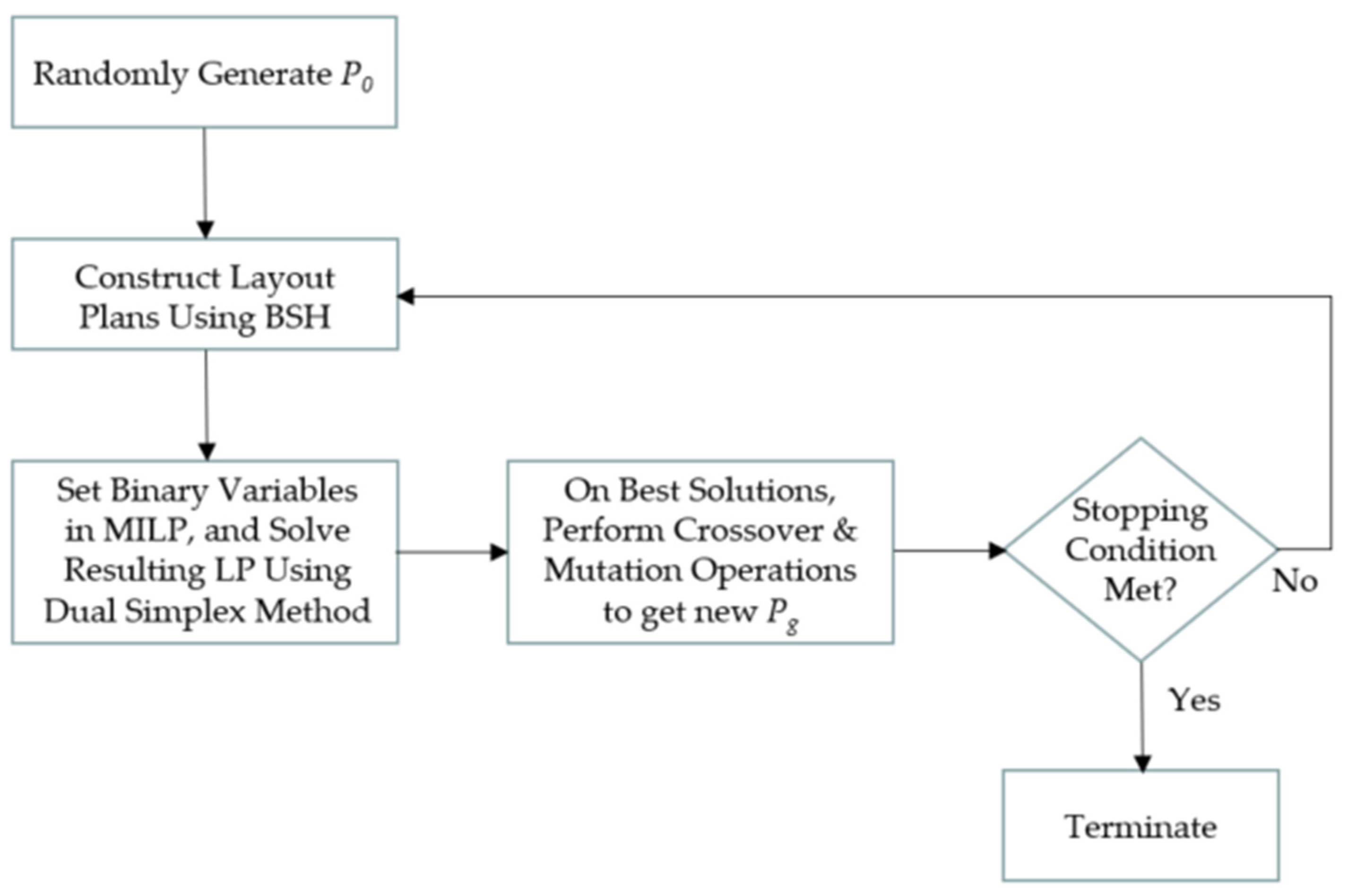
A GA is developed for the UA-FLP presented in previous sections. The proposed GA consists of a BSH, LP model, and a dual simplex method. The GA consists of the following five stages. See Figure 2 for a flow diagram of the stages of the proposed GA:
- (1)
- Randomly generate a set (or population) of solutions (P0).
- (2)
- The BSH presented in McKendall and Hakobyan [8] is used to construct the layout and determine the total weighed distance (TWD) for each solution in P0.
- (3)
- Based on BSH layout plans (obtained in stage 2), set binary variables leftij, belowij, and oi in proposed MILP, and improve layout for chromosomes in P0 or Pg using the resulting LP model and the dual simplex method.
- (4)
- Perform crossover and mutation operations on best set of solutions from stage (3) to produce a new population of solutions (Pg).
- (5)
- Repeat stages (2) through (4) on Pg until a stopping criterion is met.
The main components of the proposed GA are the solution representation, BSH, and the crossover and mutation operations. Each of these components are discussed below.
3.1. Solution (Chromosome) Representation
For the proposed GA, the solution or chromosome is represented as a permutation of the facilities {1, 2, …, N}. For example, randomly generating a chromosome for a UA-FLP with six facilities (N = 6) may produce the following chromosome π = {2, 3, 6, 5, 1, 4}.
In other words, facility 2 is in position 1 (i.e., π(1) = 2), facility 3 is in position 2 (i.e., π(2) = 3), and so on. That is, facility 2 will be placed on the plant floor first. Next, facility 3 will be placed on the plant floor and so on.
In stage 1 mentioned above, a set of chromosomes are generated randomly for the initial population P0. Note, the solution representation (chromosome) does not specify the location (xi, yi, li, wi) and orientation (oi) of each facility i. The BSH presented in McKendall and Hakobyan [8] is used to construct the layout and determine TWD for each chromosome in P0.
3.2. Boundary Search Heuristic (BSH)
The BSH presented in McKendall and Hakobyan [8] is a construction algorithm used to produce the layout and determine TWD for each chromosome in P0. Given a solution (chromosome) π a placement procedure is used to assign facilities to locations on the plant floor. First, facility in position 1 (i.e., π(1)) of π is placed first on the plant floor, then facility in position 2 (i.e., π(2)) is placed on the boundary of facility π(1). Note, the best location on the boundary is selected for the location of facility π(2) with respect to minimizing TWD. The facility in position k (i.e., π(k)), is placed on the boundary of already placed facilities (i.e., π(1), π(2), …, π(k − 1)) such that TWD is minimized and layout is feasible (i.e., facilities placed are within the boundary of the floor space). See McKendall and Hakobyan [8] for details.
At the end of stage 2, once BSH is used to generate a layout for each chromosome in P0, the variables for the MILP model (i.e., xi, yi, li, wi, dxij, dyij, oi, leftij, belowij) are obtained for each layout. In stage 3, the chromosomes are improved using the MILP model presented earlier for the UA-FLP. More specifically, the binary variables for the relative locations (i.e., leftij, belowij) and orientations (i.e., oi) obtained by BSH for each layout are used as input data in the MILP for the UA-FLP. It is important to note that if a facility i is both to the left and below a facility j, either horizontal or vertical separation is used (i.e., either leftij = 1 or belowij = 1, not both), since this would greatly restrict the solution space. Nevertheless, the resulting formulation is a linear programming (LP) model. Each LP model for each chromosome in P0 is solved efficiently using the dual simplex method. These layouts often improve the layouts constructed in stage 2. Afterward, each layout is improved using the crossover and mutation operations on the best set of solutions from stage 3. Next, the proposed GA is presented for the UA-FLP.
3.3. Crossover and Mutation Operations
The propose GA generates a number of solutions (chromosomes) and adds them to the new generation of chromosomes Pg, where g is the current generation (iteration) of the GA. At the initial iteration (g = 0), the GA starts by randomly generating the initial population of chromosomes (P0). More specifically, each chromosome in P0 is generated randomly, and the TWD and plant floor feasibility status is evaluated by constructing the layout using BSH. On the other hand, each solution in Pg, for g > 0, is either randomly generated (i.e., mutation operation is used), or it is generated from two chromosomes (solutions), randomly selected from population Pg-1 (i.e., crossover operation is used). The chromosomes obtained by applying crossover operation inherit features from both parent chromosomes. At each generation g of the GA, Max_Num_Cross chromosomes are generated using crossover operation, but only Gen_Size (Gen_Size < Max_Num_Cross) best chromosomes are kept in the new generation Pg. The generated chromosome is added to Pg, only if it is better than the worst chromosome in Pg and a chromosome similar to π has not already been added to Pg. After the new population Pg, for g > 0, is generated, Num_Rand_Chrom (Num_Rand_Chrom < Gen_Size) chromosomes are randomly generated (mutation operation), and replace the worst chromosomes in Pg. The chromosomes in each generation Pg are stored in such a way, that higher quality chromosomes precede lower quality chromosomes as in Drezner [27]. The stopping criterion for the proposed GA is the maximum amount of time Max_Duration, to run the heuristic.
As in most GAs, where the chromosome represents a permutation of numbers, as in the proposed GA, the crossover operation may produce infeasible chromosomes, if a technique is not used to generate feasible chromosomes. The following technique is used to generate feasible chromosome π, when performing the crossover operation to parents π1 and π2:
- Step 0:
- Set k1 = 0.2N, k2 = 0.5N, cross_point = 1, and num_cross_points = 0.
- Step 1:
- Set num_cross_points = num_cross_points + 1.Add crossover point cross_point to vector cross_points.Set cross_point = cross_point + Random number between k1 and k2.If cross_point ≥ N, then go to Step 2.Else go to Step 1.
- Step 2:
- Set cross_point = N and num_cross_points = num_cross_points + 1.Add crossover point cross_point to vector cross_points.Set r = 1.
- Step 3:
- Copy the genes (facilities) cross_pointsr through cross_pointsr+1 from chromosome π1 to the same positions in chromosome π.Set r = r + 2.If r < num_cross_points, go to Step 3.Else go to Step 4.
- Step 4:
- Copy all the facilities in chromosome π2 which have not been copied from π1 into positions in π which have not been filled, while preserving the precedence order of facilities in π2.
3.4. Pseudocode of the Proposed GA
The steps of the proposed GA are given below:
- π_worst = worse solution in current population g (Pg)
- Recall, in Pg, chromosomes are ordered in ascending order based on TWD.
- Step 1:
- Initialize parameters.Initialize parameters Gen_Size, Max_Num_Cross > Gen_Size, Num_Rand_Chrom, Max_Duration.Set g = 0;Set curr_parents_offspr_count = 0 (number of chromosomes generated from current pair of chromosomes using the crossover operator).Set TWD* = large number.
- Step 2:
- Start new population.Set chromosome_count = 0 (number of chromosomes generated at iteration g).
- Step 3:
- Generate chromosome.If chromosome_count ≥ Max_Num_Cross then go to step 5;ElseIf g = 0, then
- Randomly generate chromosome π.
Else- If curr_parents_offspr_count = 0 then
- Randomly pick two chromosomes π’ and π’’ from the generation Pg-1 and set π1 = π’ and π2 = π’’.
- Set curr_parents_offspr_count = curr_parents_offspr_count + 1;
Else- Set π1 = π’’, and π2 = π’.
- Set curr_parents_offspr_count = 0.
- Generate chromosome π from π1 and π2 by applying crossover operation.
Generate the layout corresponding to chromosome π using BSH. - Step 4:
- Add chromosome π to new population and run BSH with π as a starting solution.Set π_worst = Pg,Gen_Size;If chromosome_count < Gen_Size or TWD(π) < TWD(π_worst)
- If TWD(π) < TWD*
- Initialize TWD*, x*i, y*i, l*i, and w*i from the values TWD(π), xi, yi, li, and wi, respectively.
Add chromosome π to new generation Pg. When adding the chromosome to the generation, make sure that the higher quality solutions precede lower quality solutions. Also, if chromosome_count ≥ Gen_Size, then drop the worst (Gen_Size-th) chromosome from Pg.Run the dual simplex method to improve the chromosomes. This will modify the values of TWD*, x*i, y*i, l*i, and w*i, if it finds a better solution, than the best solution found thus far.Set chromosome_count = chromosome_count + 1, and go to Step 3; - Step 5:
- Check stopping criterion and add random chromosomes to the new population.If the heuristic has been running for more than Max_Duration minutes, thengo to Step 6.ElseRemove the last Num_Rand_Chrom (worst) chromosomes from Pg, and add Num_Rand_Genes randomly generated chromosomes to the generation. While adding new chromosomes to the generation, make sure that higher quality solutions precede lower quality solutions.Set g = g +1, and go to Step 2.
- Step 6:
- Output the best solution (i.e., x*i, y*i, l*i, w*i for all i = 1, …, N), and terminate the heuristic;
4. Computational Results
A set of test problems are used in this paper in order to test the performance of the proposed GA. More specifically, the first problem, P8, is an eight facility problem, which was generated randomly. The second and third problems (i.e., P20 and P50) are 20- and 50-facility problems available in the literature from the commercial software VIP-PLANOPT. Also, P20 is available in Imam and Mir [28]. For the last test problem, the floor space is unconstrained, and the Euclidean distance measure is used to determine the distances between pairs of facilities. However, the rectilinear distance measure is used on P8 and P20 test problems. Also, in all experiments, a PC (equipped with Microsoft Windows 10, an Intel Core processor with a CPU speed of 3.20 GHz and 16 GB of RAM) was used to solve the test problems, and the proposed GA was coded using the C++ programming language.
Recall, the GA parameters are Gen_Size, Max_Num_Cross, Num_Rand_Chrom, and Max_Duration. The number of random solutions, Num_Rand_Chrom, generated at each generation was set to 0.1Gen_Size. The values used for parameters Gen_Size, Max_Num_Cross, Max_Duration are shown in Table 3. Each test problem was solved five times, since the GA is stochastic, and the outcome can be different for different runs. Minimum TWDs, means, standard deviations, % Improvements, and run times are used for comparison purposes.
4.1. Test Problem P8 Results and Comparisons
As stated previously, the eight facility test problem, P8, was randomly generated. See Table 4 for a summary of the results. The proposed GA obtained a TWD of 5667.17 for each of the 1-min runs (total of five runs). However, using the MILP presented earlier and the CPLEX solver, the optimal solution was obtained in 21.3 h of computation time (CP), which gives the minimum TWD of 5637.16 (bolded in Table 4). Although the proposed GA did not obtain the optimal solution, the TWD obtained is only 0.53% (less than 1%) above the optimal TWD. Note, % Improvement = 100 × (Best TWD − TWD)/Best TWD (e.g., % Improvement = 100 × (5637.16 − 5667.17)/5637.16 = −0.53%). Although attempts were made to improve the results for the proposed GA by running the test problems for 5 min, increasing the number of runs, etc., the same TWD of 5667.17 was obtained. It is well known that stochastic heuristics like GA and simulated annealing may obtain solutions in the vicinity of the local optima, without ever converging to the local optima. Therefore, a steepest descent heuristic, as in McKendall et al. [29], can be used to ensure that the solutions obtained are local optimums. After running a simple tabu search heuristic on the final solutions obtained by the proposed GA, the optimal solutions were obtained after only a few iterations.
4.2. Test Problem P20 Results and Comparisons
As stated previously, the 20 facility test problem, P20, was taken from Imam and Mir [28]. See Table 5 for a summary of the results. The proposed GA results are compared with the results from the tabu search (TS) heuristic which consisted of the boundary search heuristic (TS/BSH) presented in McKendall and Hakobyan [18] and the multi-start simulated annealing algorithm (MS-SA) presented in Allahyari and Azab [16]. It is important to note that the test problem was solved once using TS/BSH, but the test problem was solved 10 times (i.e., 10 runs) using MS-SA heuristic, and the computation time was not given. Recall, the test problem was solved five times using the proposed GA. However, the proposed GA obtained the minimum TWD of 1147 and improved the best-found TWD in the literature (1151.4), which is bolded in Table 5, by 0.38% in much less CP time compared to TS/BSH. Also, notice how much lower the mean and standard deviation of the proposed GA are compared to the MS-SA. As a result, the proposed heuristic outperformed the other heuristics with respect to solution quality and/or CP time.
4.3. Test Problem P50 Results and Comparisons
The 50 facility test problem, P50, available in the literature from the commercial software VIP-PLANOPT, was solved once (one run) using the TS/BSH presented in McKendall and Hakobyan [18], and five times using the proposed GA. Recall, the floor space is unconstrained, and the Euclidean distance measure is used to determine the distances between pairs of facilities. See Table 6 for a summary of the results. The proposed GA obtained the minimum TWD of 71,031.24 and improved the best-found TWD in the literature (71,291.4), which is bolded in Table 6, by 0.36% in less CP time. Although each of the five runs were 60 min for the proposed GA, only one run did not produce a better result than TS/BSH.
5. Conclusions
The UA-FLP is considered in this paper and is defined as the problem of locating rectangular facilities, with fixed dimensions, on a rectangular floor space such that facilities do not overlap while minimizing the total weighted distance (TWD). This research was motivated by the investigation of layout options for a production area at the Toyota Motor Manufacturing West Virginia (TMMWV) plant in Buffalo (WV, USA). A mixed integer linear programming (MILP) model and a genetic algorithm (GA) is presented for locating facilities on a continuous plant floor. The proposed GA consists of the boundary search heuristic (BSH), a linear programming (LP) model, and the dual simplex method. The GA is used to obtain permutations of the facilities, which specify the order in which facilities should be placed on the plant floor. From these permutations, BSH is used to construct the layouts. Then the layouts are improved using the LP model and the dual simplex method. Instead of solving the problem from scratch, from one LP model to another, some of the right-hand side values of the LP model were updated/modified, and the model is quickly solved using the dual simplex method.
The computational results show that the proposed GA is effective for solving problems with 50 or less facilities, as in the UA-FLP encountered at the TMMWV plant. However, as stated previously, in some cases the simple GA may have difficulty converging to the local optimum. More specifically, the GA is a stochastic heuristic, which is good for obtaining diverse solutions but may lack in intensification (i.e., the ability to thoroughly explore the regions of these diverse solutions). As a result, for future research, the tabu search (TS) heuristic can be used to search for the local optimum for each chromosome during each generation (i.e., intensify the search). This would require the development of a memetic heuristic (e.g., hybrid GA and TS heuristic) for the UA-FLP. Otherwise, a hybrid heuristic could be developed, which uses the diversification strategies of simulated annealing and intensification strategies of tabu search. These heuristics can be compared to the proposed GA.
Author Contributions
Conceptualization, A.M. and A.H.; methodology, A.M. and A.H.; software, A.H.; validation, A.M.; writing—original draft preparation, A.M.; writing—review and editing, A.M. and A.H.; supervision, A.M. All authors have read and agreed to the published version of the manuscript.
Funding
This research received no external funding.
Institutional Review Board Statement
Not applicable.
Informed Consent Statement
Not applicable.
Data Availability Statement
Not applicable.
Acknowledgments
We would like to thank Shamaya Morris and Don Stewart of Toyota Motor Manufacturing West Virginia (TMMWV) plant in Buffalo, WV for giving us the opportunity to work on TMMWV’s facility layout problem. Also, we would like to thank the anonymous reviewers for their constructive comments.
Conflicts of Interest
The authors declare no conflict of interest.
References
- Tompkins, J.A.; White, J.A.; Bozer, Y.A.; Frazelle, E.H.; Tanchoco, J.M.A.; Trevino, J. Facilities Planning; John Wiley: New York, NY, USA, 1996. [Google Scholar]
- Francis, R.L.; McGinnis, L.F.; White, J.A. Facility Layout and Location: An Analytical Approach; Prentice-Hall: Englewood Cliff, NJ, USA, 1992. [Google Scholar]
- Montreuil, B. A modelling framework for integrating a layout design and flow network design. In Proceedings of the Material Handling Research Colloquium, Hebron, KY, USA, 19–21 June 1990. [Google Scholar]
- Heragu, S.S.; Kusiak, A. Efficient models for the facility layout problem. Eur. J. Oper. Res. 1991, 53, 1–13. [Google Scholar] [CrossRef]
- Kusiak, A.; Heragu, S.S. The facility layout problem. Eur. J. Oper. Res. 1987, 29, 229–251. [Google Scholar] [CrossRef]
- Meller, R.D.; Gau, K.Y. The facility layout problem: Recent and emerging trends and perspectives. Int. J. Prod. Res. 1996, 15, 351–366. [Google Scholar] [CrossRef]
- Anjos, M.F.; Vieira, M.V. Mathematical optimization approaches for facility layout problems: The state-of-the-art and future research directions. Eur. J. Oper. Res. 2017, 261, 1–16. [Google Scholar] [CrossRef] [Green Version]
- Perez-Gosende, P.; Mula, J.; Diaz-Madronero, M. Facility layout planning. An extended literature review. Int. J. Prod. Res. 2021, 59, 3777–3816. [Google Scholar] [CrossRef]
- Xiao, Y.; Seo, Y.; Seo, M. A two-step heuristic algorithm for layout design of unequal-sized facilities with input/output points. Int. J. Prod. Res. 2013, 51, 4200–4222. [Google Scholar] [CrossRef]
- Park, H.; Seo, Y. An efficient algorithm for unequal area facilities layout planning with input and output points. INFOR 2019, 57, 56–74. [Google Scholar] [CrossRef]
- Dunker, T.; Radons, G.; Westkamper, E. A coevolutionary algorithm for a facility layout problem. Int. J. Prod. Res. 2003, 41, 3479–3500. [Google Scholar] [CrossRef]
- Asl, A.D.; Wong, K.Y. Solving unequal-area static and dynamic facility layout problems using modified particle swarm optimization. J. Intell. Manuf. 2017, 28, 1317–1336. [Google Scholar]
- Lee, Y.H.; Lee, M.H. A shape-based block layout approach to facility layout problems using hybrid genetic algorithm. Comput. Ind. Eng. 2002, 42, 237–248. [Google Scholar] [CrossRef]
- Ingole, S.; Singh, D. Unequal-area, fixed-shape facility layout problems using the firefly algorithm. Eng. Optim. 2017, 49, 1097–1115. [Google Scholar] [CrossRef]
- Ingole, S.; Singh, D. Fixed and flexible shape facility layout problems using biogeography-based optimisation algorithm. Int. J. Ind. Syst Eng. 2021, 37, 84–118. [Google Scholar]
- Allahyari, M.Z.; Azab, A. Mathematical modeling and multi-start search simulated annealing for unequal-area facility layout problem. Expert Syst. Appl. 2018, 91, 46–62. [Google Scholar] [CrossRef]
- Liu, J.; Zhang, H.; He, K.; Jiang, S. Multi-objective particle swarm optimization algorithm based on objective space division for the unequal-area facility layout problem. Expert Syst. Appl. 2018, 102, 179–192. [Google Scholar] [CrossRef]
- McKendall, A.R.; Hakobyan, A. Heuristics for the dynamic facility layout problem with unequal-area departments. Eur. J. Oper. Res. 2010, 201, 171–182. [Google Scholar] [CrossRef]
- Hakobyan, A.; McKendall, A. A hybrid heuristic for the unequal-area dynamic facility layout problem. Int. J. Math. Oper. Res. 2013, 5, 743–763. [Google Scholar] [CrossRef]
- Welgama, P.S.; Gibson, P.R. A contruction algorithm for the machine layout problem with fixed pick-up and drop-off points. Int. J. Prod. Res. 1993, 31, 2575–2589. [Google Scholar] [CrossRef]
- Mir, M.; Imam, M.H. A hybrid optimization approach for layout design of unequal-area facilities. Comput. Ind. Eng. 2001, 39, 49–63. [Google Scholar] [CrossRef]
- Kim, M.; Chae, J. A monarch butterfly optimization for an unequal area facility layout problem. Soft Comput. 2021. [Google Scholar] [CrossRef]
- Garcia-Hernandez, L.; Salas-Morera, L.; Garcia-Hernandez, J.A.; Salcedo-Sanz, S.; Valente de Oliveira, J.A. Applying the coral reefs optimization algorithm for solving unequal area facility layout problems. Expert Syst. Appl. 2019, 138, 112819. [Google Scholar] [CrossRef]
- Palomo-Romero, J.M.; Salas-Morera, L.; Garcia-Hernandez, L. An island model genetic algorithm for unequal area facility layout problems. Expert Syst. Appl. 2017, 68, 151–162. [Google Scholar]
- Kulturel-Konak, S.; Konak, A. Linear programming based genetic algorithm for the unequal area facility layout problem. Int. J. Prod. Res. 2013, 51, 4302–4324. [Google Scholar] [CrossRef]
- Gonçalves, J.F.; Resende, M.G.C. A biased random-key genetic algorithm for the unequal area facility layout problem. Eur. J. Oper. Res. 2015, 246, 86–107. [Google Scholar] [CrossRef] [Green Version]
- Drezner, Z. A new genetic algorithm for the quadratic assignment problem. INFORMS J. Comput. 2003, 15, 320–330. [Google Scholar] [CrossRef]
- Imam, M.H.; Mir, M. Automated layout of facilities of unequal areas. Comput. Ind. Eng. 1993, 24, 355–366. [Google Scholar] [CrossRef]
- McKendall, A.R.; Shang, J.; Kuppusamy, S. Simulated annealing heuristics for the dynamic facility layout problem. Comput. Oper. Res. 2006, 33, 2431–2444. [Google Scholar] [CrossRef] [Green Version]
Figure 1.
Optimal layout for small UA-FLP instance.

Figure 2.
Flow diagram of the stages of the proposed GA.


Table 1.
Data for small UA-FLP instance.
| Facility | Length | Width | (fij) | |||||
|---|---|---|---|---|---|---|---|---|
| (i) | (ai) | (bi) | 1 | 2 | 3 | 4 | 5 | 6 |
| 1 | 2 | 4 | - | 51 | 0 | 23 | 17 | 29 |
| 2 | 2 | 3 | 25 | - | 40 | 10 | 35 | 0 |
| 3 | 2 | 2 | 0 | 15 | - | 0 | 60 | 12 |
| 4 | 1 | 2 | 20 | 30 | 10 | - | 0 | 50 |
| 5 | 1 | 3 | 36 | 0 | 43 | 0 | - | 23 |
| 6 | 3 | 4 | 16 | 48 | 0 | 19 | 0 | - |
| Building (L × W) | 5 | 10 | ||||||
Table 2.
Output data (optimal solution) for small UA-FLP instance.
| Facility (i) | xi | yi | li | wi | oi |
|---|---|---|---|---|---|
| 1 | 4 | 4 | 2 | 4 | 1 |
| 2 | 1.5 | 4 | 3 | 2 | 0 |
| 3 | 1.5 | 1 | 2 | 2 | 0 |
| 4 | 2 | 5.5 | 2 | 1 | 0 |
| 5 | 1.5 | 2.5 | 3 | 1 | 0 |
| 6 | 2 | 7.5 | 4 | 3 | 0 |
Table 3.
GA heuristic parameter setting.
| Problem Instance | Gen_Size | Max_Num_Cross | Max_Duration (Minutes) |
|---|---|---|---|
| P8 | 10 | 20 | 1 |
| P20 | 30 | 60 | 15 |
| P50 | 40 | 80 | 60 |
Table 4.
Summary of results for test problem P8.
| Method | Min TWD | Mean TWD | Std. Dev. | % Improvement | CP Time |
|---|---|---|---|---|---|
| Proposed GA | 5667.17 | 5667.17 | 0 | −0.53 | 1 m |
| MPL/CPLEX | 5637.16 | -- | -- | 0 | 21.3 h |
Table 5.
Summary of results for test problem P20.
| Method | Min TWD | Mean TWD | Std. Dev. | % Improvement | CP Time |
|---|---|---|---|---|---|
| Proposed GA | 1147 | 1152.08 | 5.64 | 0.38 | 15 m |
| TS/BSH [18] | 1151.4 | -- | -- | 0 | 2.9 h |
| MS-SA [16] | 1218.75 | 1270.55 | 20.09 | −5.85 | -- |
Table 6.
Summary of results for test problem P50.
| Method | Min TWD | Mean TWD | Std. Dev. | % Improvement | CP Time |
|---|---|---|---|---|---|
| Proposed GA | 71,031.24 | 71,401.19 | 424.29 | 0.36 | 60 m |
| TS/BSH [18] | 71,291.4 | - | - | 0 | 2.1 h |
Publisher’s Note: MDPI stays neutral with regard to jurisdictional claims in published maps and institutional affiliations. |
© 2021 by the authors. Licensee MDPI, Basel, Switzerland. This article is an open access article distributed under the terms and conditions of the Creative Commons Attribution (CC BY) license (https://creativecommons.org/licenses/by/4.0/).
Share and Cite
MDPI and ACS Style
McKendall, A.; Hakobyan, A. An Application of an Unequal-Area Facilities Layout Problem with Fixed-Shape Facilities. Algorithms 2021, 14, 306. https://0-doi-org.brum.beds.ac.uk/10.3390/a14110306
AMA Style
McKendall A, Hakobyan A. An Application of an Unequal-Area Facilities Layout Problem with Fixed-Shape Facilities. Algorithms. 2021; 14(11):306. https://0-doi-org.brum.beds.ac.uk/10.3390/a14110306
Chicago/Turabian StyleMcKendall, Alan, and Artak Hakobyan. 2021. "An Application of an Unequal-Area Facilities Layout Problem with Fixed-Shape Facilities" Algorithms 14, no. 11: 306. https://0-doi-org.brum.beds.ac.uk/10.3390/a14110306
Note that from the first issue of 2016, this journal uses article numbers instead of page numbers. See further details here.