Analysis of the Vibration Mitigation Characteristics of the Ballasted Ladder Track with Elastic Elements


School of Civil Engineering, Beijing Jiaotong University, Beijing 100044, China
*
Author to whom correspondence should be addressed.
Sustainability 2019, 11(23), 6780; https://0-doi-org.brum.beds.ac.uk/10.3390/su11236780
Submission received: 5 November 2019
/
Revised: 26 November 2019
/
Accepted: 27 November 2019
/
Published: 29 November 2019
(This article belongs to the Collection Sustainable Rail and Metro Systems)
Abstract
:Despite the fact railways are seen as an environmentally friendly and sustainable form of transport, however, the train-induced vibration has been seen as a negative environmental consequence. The ballasted ladder track is one type of ballasted track with longitudinal sleepers. The elastic elements can not only protect the track structure but also control the vibration. To investigate the vibration mitigation effects of ballasted ladder track with elastic elements, a finite element - infinite element (FE-IFE) model was built considering the elastic elements of under-sleeper pads (USPs) and under-ballast mats (UBMs). This model was validated by a laboratory test. Then, the moving train load was obtained based on the multi-body dynamics (MBD)-finite elements method (FEM) analysis. The vibration mitigation effects of the ballasted ladder track with different types of elastic elements were calculated compared with the ballasted tracks without elastic elements. The results indicate that: (1) the ballasted ladder track has the advantage of vibration reduction at low frequencies, with a maximum vibration attenuation of 25.2 dB and an averaged vibration attenuation of 19.0 dB between 5 and 20 Hz through the ballast. (2) The ballasted ladder track with USPs or UBMs can provide better vibration attenuation between 30 and 100 Hz, but it induces a vibration amplification between 5 and 30 Hz. (3) The ballasted ladder track with elastic elements in different cases can provide different vibration mitigation effects. The ballasted ladder track with both USPs and UBMs can provide the best mitigation effect with an average vibration mitigation of approximately 15 dB and a maximum vibration mitigation of 30 dB between 30 and 100 Hz.
1. Introduction
The ladder track is a type of longitudinal sleeper track. Two longitudinal pre-stressed concrete beams, which are connected by steel pipes, are designed to fix and support the rails. The rails and ladder sleepers are combined to form complex longitudinal beams, resulting in good bearing capacity and transverse stability.
The idea of the ladder track was originally from Baulk Road and was then applied in the Leeds and Selby Railway in 1830. From the middle of the 20th century, systematic research started on the ladder track in Japan, Russia and France. Three types of the ladder track have been developed: the tubular modular track was developed by Peter Kusel, the floating ladder track and the ballasted ladder track were developed by the Railway Technical Research Institute (RTRI) of Japan, and the specialised track system was developed in South Africa.
In recent years, the ballasted ladder track has gradually attracted people’s attention. The ballasted ladder track has good performance in vibration mitigation and track durability [1] evaluated the longitudinal and lateral bearing capacity for ballasted ladder track by loading tests. The lateral bearing capacity is approximately twice that of the conventional ballasted track. The ballasted ladder track was also tested at the Transportation Technology Centre Inc. (TTCI) in Colorado, USA [2,3]. Younesian et al. [4] investigated the dynamic performance of the ballasted ladder track, and ladder units with 6 and 12 m lengths were compared. Moreover, due to the special longitudinal sleeper structure, ballasted ladder track has the potential ability to reduce the dynamic load on the ballast and the subgrade. For this reason, and because the structure promises a better and enduring track geometry, ladder track promises vibration-mitigating characteristics for freight traffic [5]. Ma et al [6] investigated the vibration reduction effect of the ballasted ladder track by a laboratory test and in situ experiment methods. Watanabe [7] used a 3D full-scale model and performed a vibration test to analysis the ground vibration characteristics of ballasted ladder track. Jing et al. [8] has done abundant research on the lateral resistance of ballasted ladder sleepers including a series of full-scale lateral track panel tests and calculation with the discrete element method. The reviews above demonstrates that the ballasted ladder track can be used to control train-induced environmental vibrations, although there are no elastic elements.
To control the vibration for the traditional ballasted track, rail pads, under-sleeper pads (USPs) and under-ballast mats (UBMs), which are widely used as typical elastic elements, can decrease the supporting stiffness of the track system and then leads vibration attenuation. This vibration- mitigation methods can enhance sustainability and efficacy in the railway industry. Wei et al. [9,10,11,12] did lots of studies on the vibration attenuation effects of rail pads. He did the laboratory test and numerical simulation to study the frequency-dependent dynamic properties of rail pads. The results indicated that the rail pads are sensitive to high frequencies. Sol-Sánchez et al. [13] has investigated the elastic elements including rail pads, USPs and UBMs used in the ballasted track. Thompson et al. [14] reviewed the USPs and UBMs which decreased the stiffness of the ballast layer. Costa et al. [15] compared the vibration mitigation characteristics of the mats under the ballast and subballast cases by numerical studies. Kraskiewicz et al. [16] focused on static and dynamic characteristics of different types of resilient mats including under-ballast mats and slab track mats for vibration isolation of railway tracks. Auersch [17] compared the dynamic axle loads on the track with and without UBMs by numerical study and analysed the influence of different parameters.
There are also some studies on the effects of USPs and UBMs on the track structure in recent years. Abadi et al. [18] did a cycling load test to investigate the potential of USPs to reduce the maintenance requirement of the track. Navaratnarajah et al. [19], Ngo T et al. [20] and Jayasuriya et al. [21] obtained laboratory results from large-scale impact tests to investigate the influence of USPs on the deformation and degradation of ballast. Insa et al. [22] focused on the application of USP in the transition zone by numerical models. Li and McDowell [23] built a discrete element method numerical model to focus on the use of USP to solve the track settlement problem. Paixao et al. [24] applied experimental tests and numerical models to investigate the track dynamic response at a transition zone where two types of USPs were installed. Focus on the bridge in urban rail transit. Liang et al. [25] investigated the damping pad floating slab which can play an important role as UBMs in the vibration damping track structure.
From the review above, one can find there are few piece of research on, but it is very interesting to investigate, the dynamic behavior and vibration mitigation effects of the ballasted ladder track with elastic elements, e.g., USPs and UBMs. In the present study, firstly, a finite element-infinite element (FE-IFE) model was built by ABAQUS including the rail, fasteners, ballasted ladder track and soil. Then, to validate the numerical model, a ballasted ladder track without elastic elements was constructed in the laboratory. By applying an impulse load, the vibration attenuation was measured and compared with the calculated results.
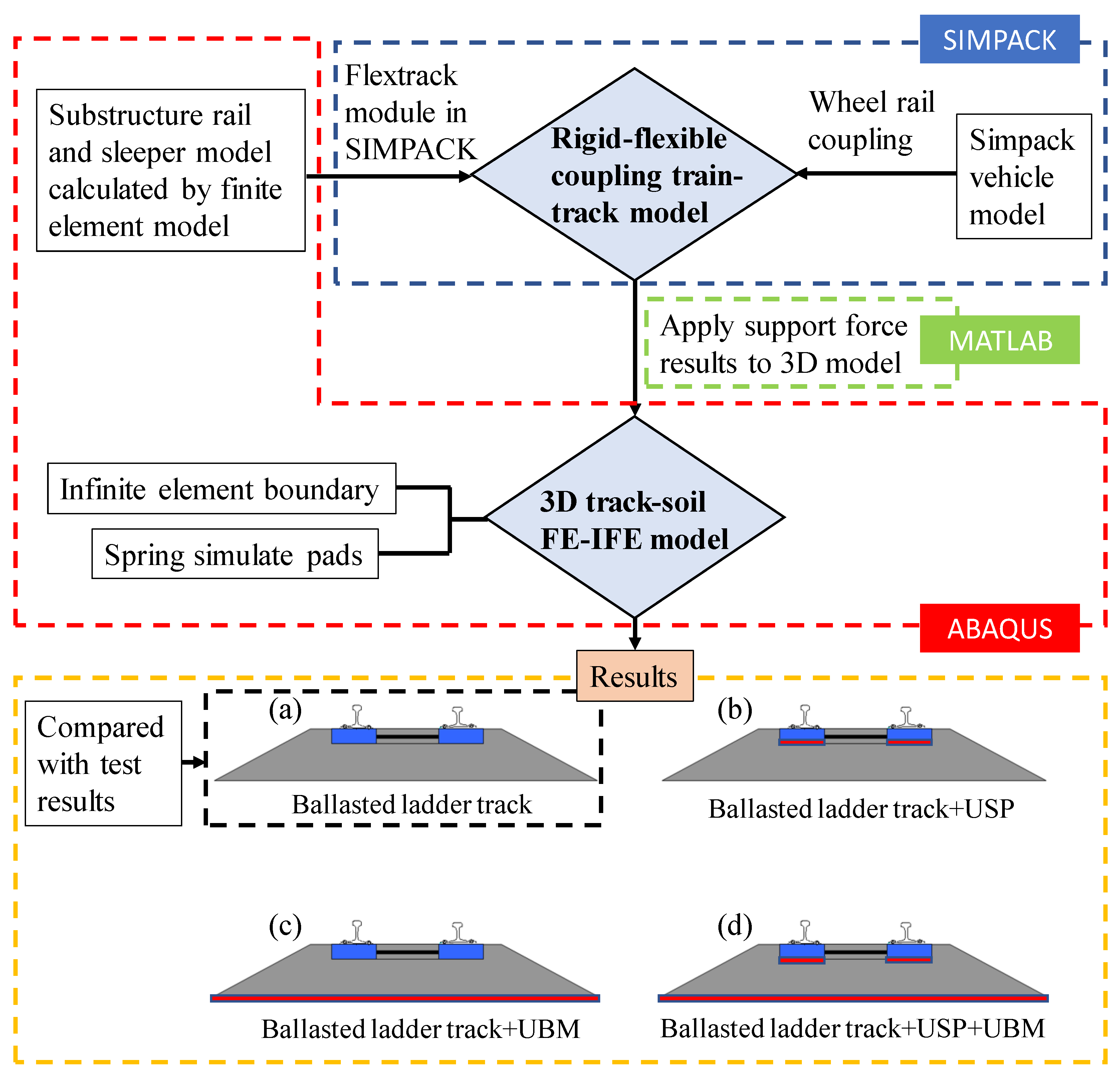
Finally, as illustrated in Figure 1, the moving train load was calculated based on the multi-body dynamics (MBD) - finite elements method (FEM) rigid-flexible coupled analysis using SIMPACK and ABAQUS. The MBD-FEM rigid-flexible train-track model is built and coupled by SIMPACK software while the track model should be built in ABAQUS software previously as the special boundary situation in the rigid-flexible coupling model. The track-soil model can also be built in ABAQUS software and already be validated by the laboratory test. Due to the large number of elements, it costs a very long calculation time. To improve the calculation efficiency, the model was divided into two parts: a train-track model by MBD-FEM rigid-flexible coupled method and a track-soil model by FE-IFE model. The supporting forces on the fastener were obtained by the first model and then applied to the track-soil model. By using MATLAB, the results can be directly extracted and applied to the track-soil model. In this way, the calculation efficiency can be largely improved. The vibration mitigation effects of the ballasted ladder track with different types of elastic elements were calculated compared with the ballasted tracks without elastic elements. Four cases were considered including the ballasted ladder track without elastic elements (validated), only with USPs, only with UBMs and with both USPs and UBMs.
2. FE-IFE Track-Soil Model
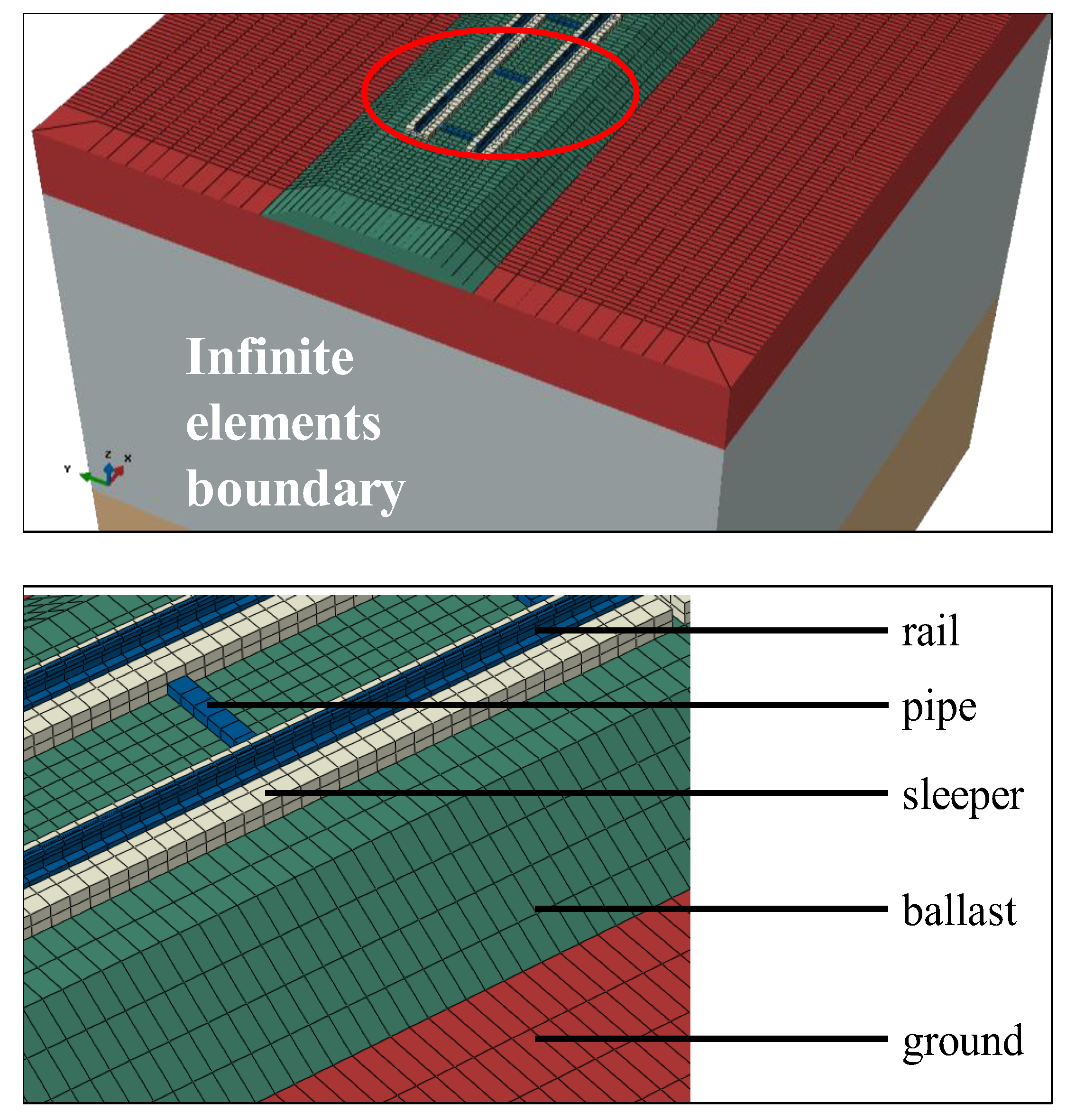
A 3D FE-IFE coupled track-soil model was built by the software ABAQUS to calculate the vibration mitigation results about the ballasted ladder track. The rail, ladder sleeper, steel pipes, ballast and soil were simulated by finite elements and the fasteners were simulated by Kelvin’s elements. To avoid the wave reflection at the boundaries in the dynamic analysis, the infinite element boundary [26,27] and perfect matched layer (PML) [28] were used. Considering the convenience of the model building, the infinite element boundary was chosen in this numerical model. Figure 2 shows the 3D FE-IFE track-soil model in the finite element software ABAQUS.
Because the ballast is a discrete medium, it is difficult to model in dynamic analysis. Three types of models can be selected for the ballasted track. Firstly, the ballast was modelled by the discrete element method [8,29,30], which is usually used for the analysis of ballast settlement and ballast dynamic characteristics. Secondly, the ballast was modelled by solid elements with the finite element method [7,15,31], which is widely used to analyse the ground vibration or the vibration mitigation of tracks. Thirdly, the ballast was represented by distributed springs and dampers [32,33], which are widely used to analyse the ground vibration and the vibration mitigation of tracks. Galvín et al [31] established a model of ballasted track by 2.5D solid elements and simplified spring-damper elements. A comparison of the predicted and measured free field velocity showed that the continuum model of the ballast and the embankment leads to a relatively good approximation at low frequencies where the quasi-static contribution to the response dominates.
As the dynamic strain of the train-induced ground vibration is usually smaller than 10−5, soils behave elastically according by Ishihara [34]. Therefore, in the 3D track-soil model, the ground was modelled by linear elastic elements. The displacement between the soil layers is coordinated. The simulated duration of train-track model and track-soil model is 6 s, the integration step is 0.005 s and the upper frequency limit is 100 Hz. The model has 106290 elements in total. The element type is the 8-node hexahedral element Based on the Rayleigh damping assumption, the factors α and β can be calculated by:
where is damping ratio and is the frequency of concern.
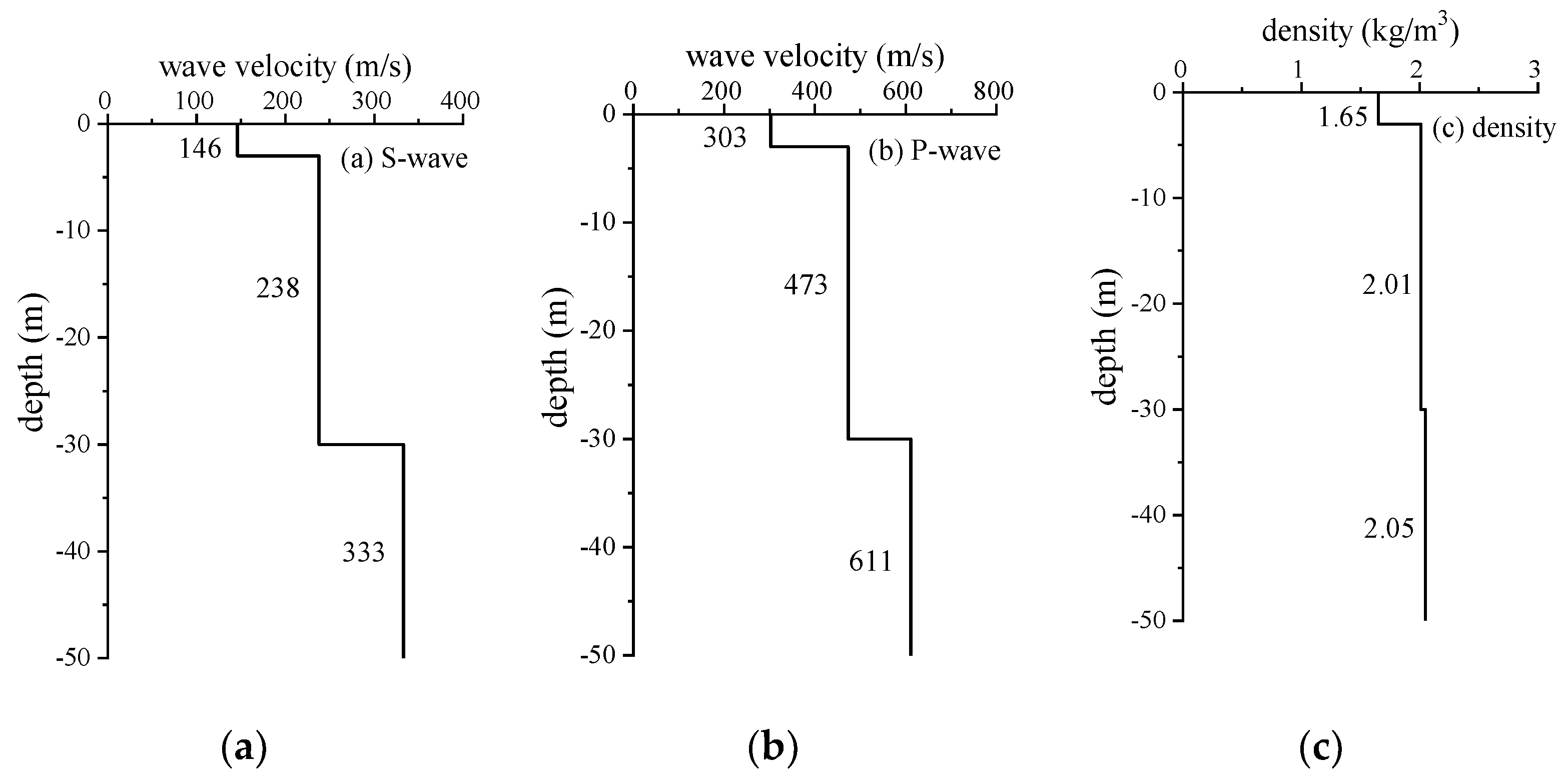
The track-soil model parameters are listed in Table 1. The track parameters were provided by the manufacturer, and the ballast parameters were from [6,17,35]. The soil parameters were measured by spectral analysis of surface waves (SASW) method in the campus where a ballasted ladder track for model validation was constructed (Figure 3).
The S-wave and P-wave velocity can be obtained by:
where E is Young modulus, is density and is Poisson’s ratio.
The parameters of 3D FE-IFE track soil model are summarized in Table 1.
3. Laboratory Test and Model Validation
3.1. Test Introduction and Test Results
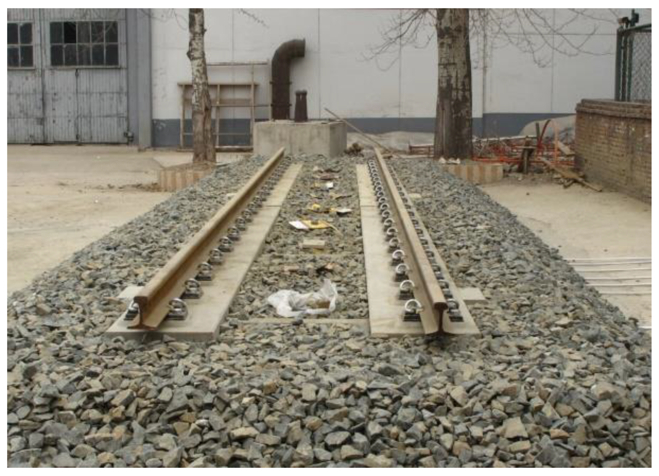
To validate the track-soil model, in the laboratory, a section of ballasted ladder track with two ladder sleepers but without any elastic elements was constructed (Figure 3 and Figure 4). The measurement equipment included a data acquisition instrument and acceleration sensors. The type INV3020D data acquisition instrument has 24 bit-ΔΣ mode AD converters, with at most 32 parallel channels. The Lance AS type acceleration sensors were installed on the rail, sleeper and ground at the middle section of one ladder cell of 6 m in length. The measurement range of sensors reaches 200 g, 20 g and 3 g for the three different locations, respectively.
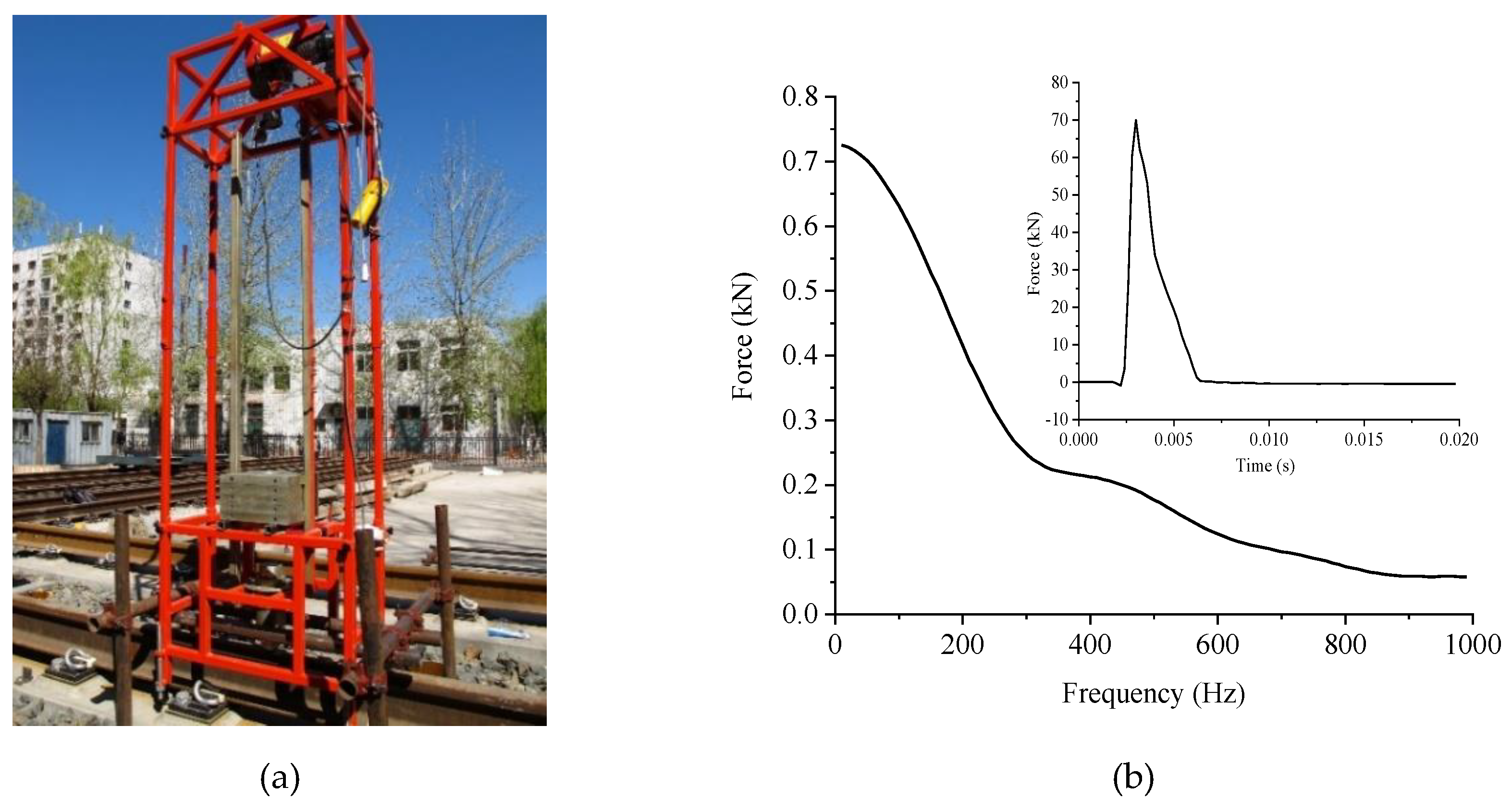
As the vibration source, an automatic falling weight system, shown in Figure 5a, was designed and was employed to impulse the rails. The masses can be hoisted at different heights by an electromagnet. It can be regarded as the motion of a free-falling body when neglecting the small friction between the masses and the guiding poles.
At most, 13 masses can be installed, each of which was approximately 14.6 kg. By changing the number of masses and drop height, different impulse forces can be obtained. A force sensor was installed in the hammer head. The material of the hammer head can also be changed to aluminium, rubber, nylon and steel. To avoid influence on the sleeper by the mass of the setup, a scaffold was installed to support the equipment.
In the test research, five masses with a total mass of 73 kg were installed. An aluminium hammer head was used, and the drop height was 10 cm. The sampling frequency for the force signal was 12.8 kHz, and the sampling frequency for the acceleration signal was 1600 Hz. The technique of varied-time-base (VTB) was employed with a VTB factor of 8 [36]. The typical time history and spectrum of impulse forces with a peak value of approximately 70 kN are shown in Figure 5b.
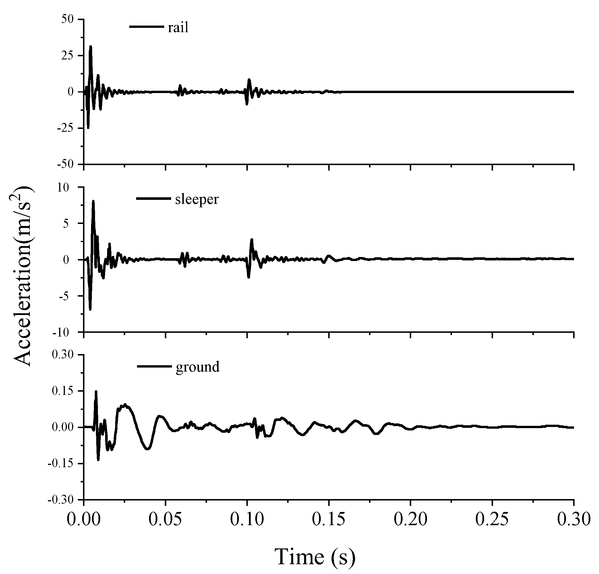
The typical records of the time history are shown in Figure 6. For further analysis in the one-third octave frequency bands, the responses due to the bound of the drop weight were cut off, and only the main impulse effect was considered. The results calculated in Figure 7 were averaged from at least ten useful records for each measurement location.
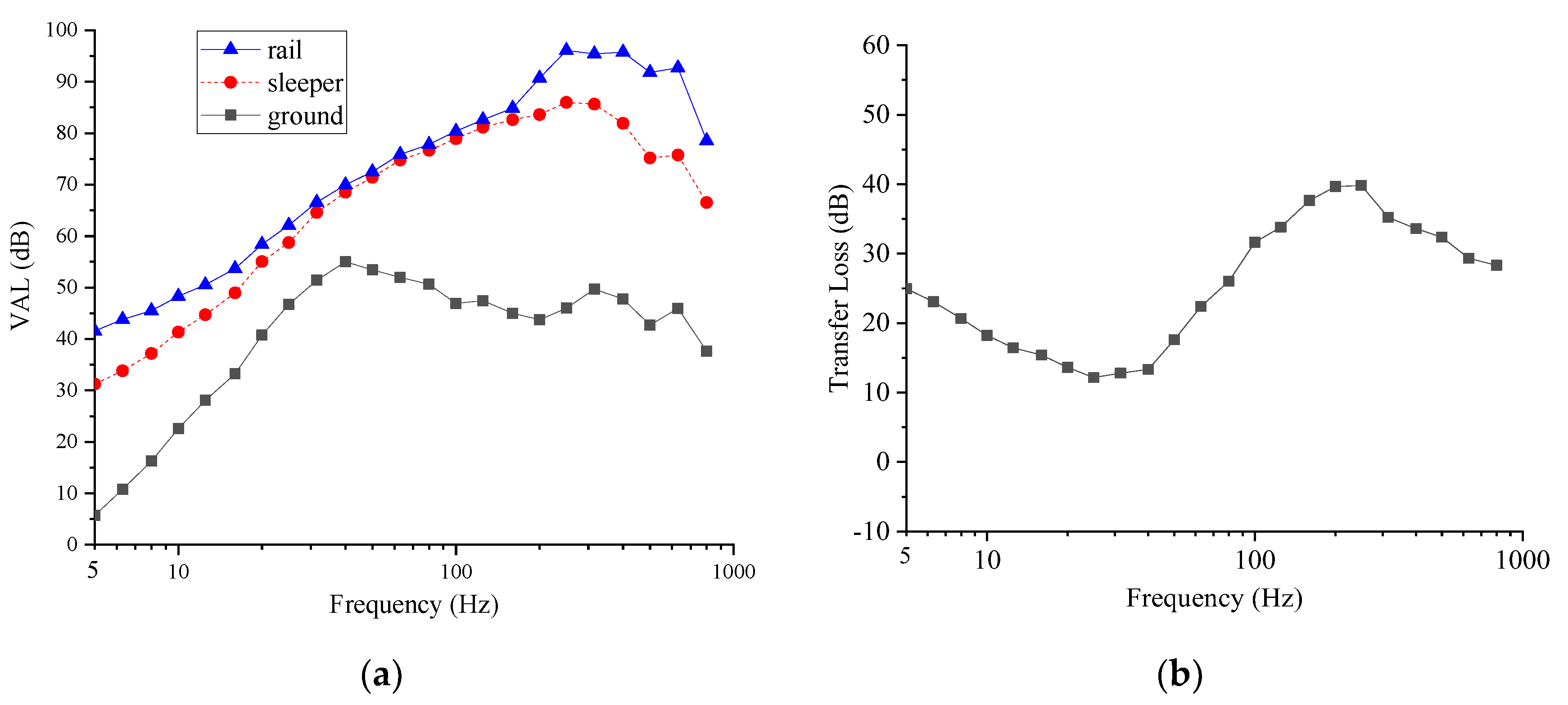
Figure 7a shows the test results including unweighted vibration acceleration level (VAL) in vertical direction on the rail sleeper and ground. The VAL in rail, sleeper and ground can be expressed as:
where arms(fi) is the root-mean-square value of acceleration at the one-third octave band central frequency fi, a0 = 10−6 m/s2 is the reference acceleration.
Figure 7b shows the transfer loss (TL) of the ballasted ladder tracks. The TL between the sleeper and ground is expressed as:
where asleeper(fi) and aground(fi) are the acceleration responses on the ladder sleeper and ground, respectively; fi is the one-third octave center frequency. The track structure has different vibration mitigation effects in different frequency bands. Accordingly, different VAL and TL values are calculated at different one-third octave center frequencies in Figure 7.
Figure 7a illustrates that the ballast plays an important role for vibration absorption above 40 Hz. Below 20 Hz, vibrations attenuate from the rail to sleeper, more in the lower frequencies than in the higher frequencies. Vibrations attenuate much more through ballast than through fasteners at these frequencies. The result of Figure 7b shows more intuitively that the ballast plays an important role in vibration attenuation between 5 and 20 Hz and above 40 Hz. The test results show that a maximum vibration attenuation of 25.2 dB and an average vibration attenuation of 19.0 dB can be obtained between 5 and 20 Hz through the ballast.
To learn more about the dynamic behaviour of the ballasted ladder track, a modal test is performed. The LC1303 force hammer is used, which can measure the maximum force of 100 kN. Nylon hammer head is installed due to the mainly concerning frequency ranges 1~100 Hz. Table 2 shows the first six mode shapes, natural frequencies and damping ratio of ladder sleeper on the ballast. It can be observed that the first natural frequency is 60.6 Hz, which affects the vibration attenuation in higher frequencies. The energy consumption of ballast plays an important role for the vibration attenuation below 20 Hz.
3.2. Model Validation
The results from the laboratory test were used to validate the numerical model introduced in Section 2.
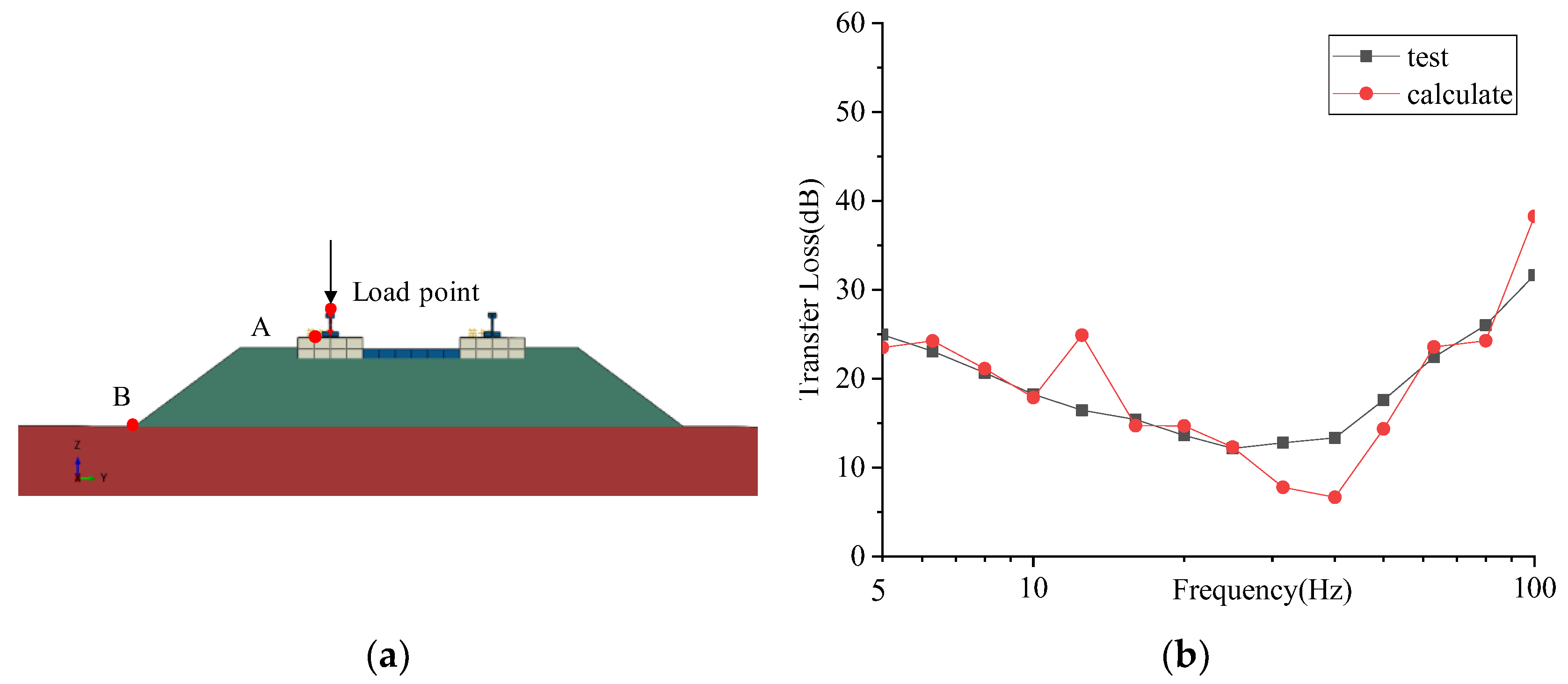
The measured force signal in Figure 5b was applied to the load point of the rail which modelled in FE-IFE track-soil model. Then, the two graphs of TL about laboratory test from sleeper to ground and computer calculating from point A to B in Figure 8a can be obtained. Generally, the tested and calculated TL had the same magnitude and match well, especially most frequency ranges between 5 and 100 Hz. Because the main influencing frequency of environmental vibrations on human beings ranges below 80 Hz, the comparisons above prove the validity of the model, which will be used to study the vibration responses induced by train loads.
4. Dynamic Analysis of Ballasted Ladder Track with Elastic Elements under Train Loads
In order to investigate the mitigation effect of ballasted ladder track with elastic elements under moving train loads, the dynamic analysis of ballasted ladder track with different type of elastic elements under train loads by MBD-FEM analysis was performed as follows.
4.1. Train Loads
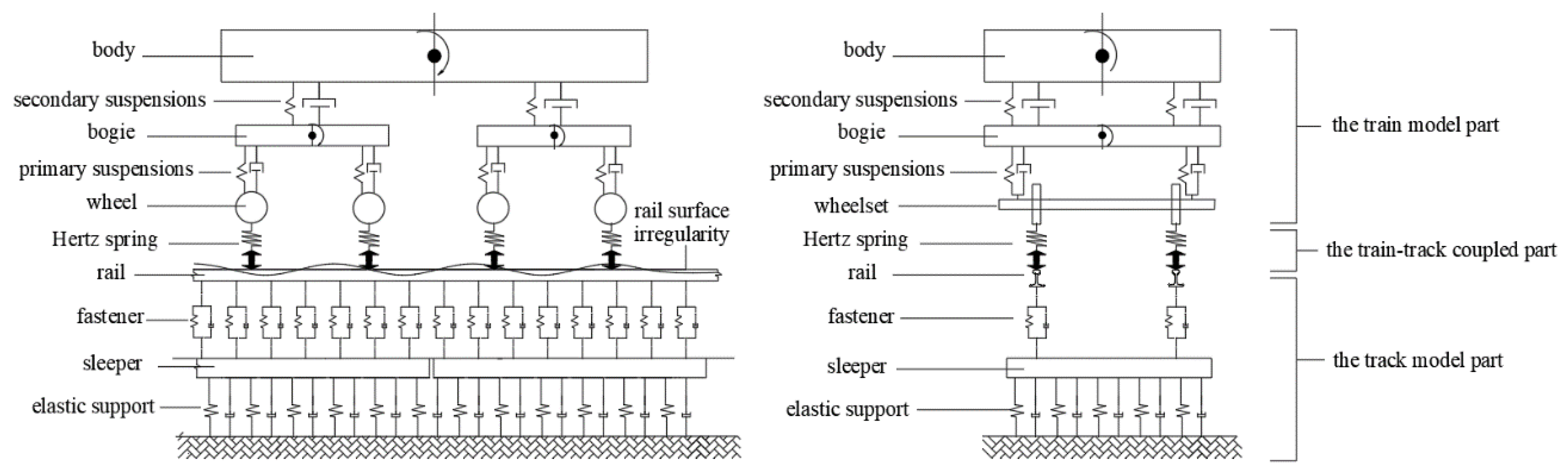
The MBD-FEM rigid-flexible coupled model was built to simulate the train loads. The MBD software SIMPACK has been widely used for 3D train-track dynamic analysis. As illustrated in Figure 9, the vehicle body, bogies and wheels were regarded as rigid bodies, while the primary and secondary suspensions were modelled as the Kelvin’s elements.
The dynamic equation of the vehicle system can be formulated as:
where is the displacement, is the mass matrix, is the damping matrix, is the stiffness matrix and is the dynamic load induced by vehicle gravity and track irregularity, all of which were built in SIMPACK. The details for matrices and equations of the moving train is shown in the researched by Ji et al. [37], Li et al. [38] and Ling et al. [39].
The rails and the sleepers were flexible, and their displacements can be calculated by modal superposition method:
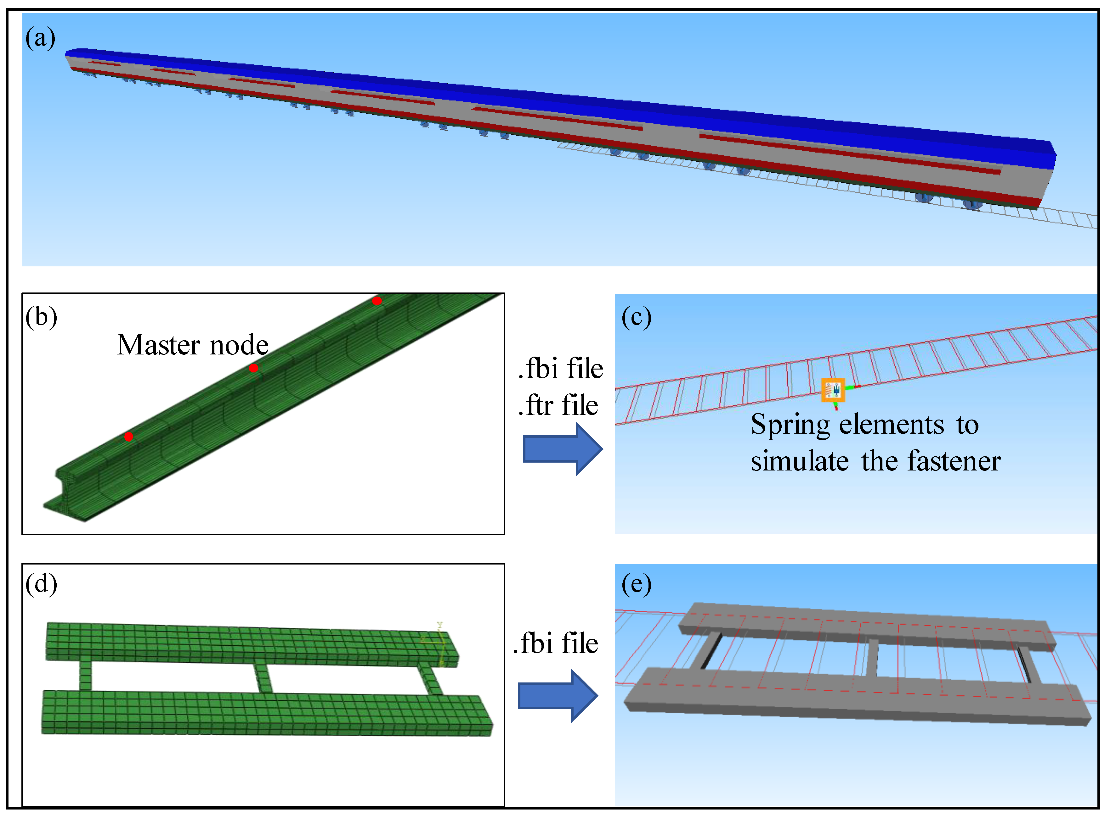
where is the modal matrix and is the displacement, N is the intercepted modal numbers of rail and sleeper, all of which were built by ABAQUS and the dynamic information was reduced to the master nodes (shown as Figure 10).
The train model consisted of six carriages. Each carriage has 42 degrees, and the parameters of the train are listed in Table 3. The rails and sleepers were considered as flexible models. Before coupled with SIMPACK, the mass, stiffness, damping and modal matrices of the rails and sleepers were calculated in ABAQUS. The information was merged to the master nodes by Guyan condensation method [40] and the information is output as a *.fbi file. The master nodes were selected with an interval of 0.15 m at the rail top. The spacing between fasteners was 0.6 m. At least four master nodes were selected between two fasteners.
After finishing the substructure analysis and modal analysis, the information of the stiffness matrix, mass matrix, geometry and modes were input into SIMPACK. The wheel-rail vertical contact was modelled by the Hertz spring, and the wheel-rail lateral contact laterally considers the Kalker creep [41].
The train speed simulated in this model was 90 km/h and the simulated duration of the model is 6 s. The track irregularity is power spectral density (PSD) functions for Federal Railroad Administration (FRA) class 6 tracks.
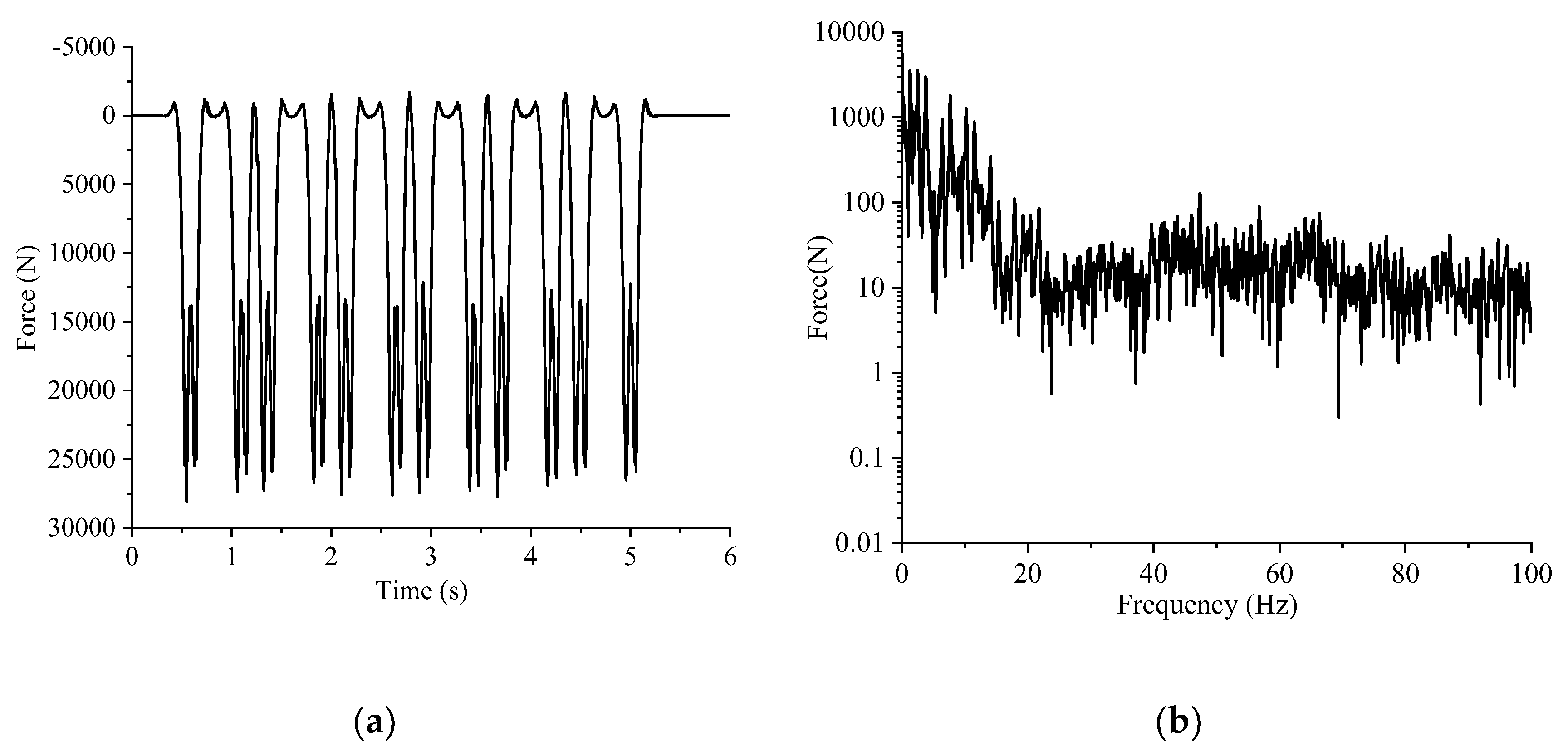
The numerical results calculated by the rigid-flexible coupled train-track model were extracted by MATLAB, and then applied on each sleeper in 3D FE-IFE track-soil model. The calculated train loads under each fastener varied with the fastener location, which had similar time histories and Fourier spectra but had different phases. A typical train load in time and frequency domains were demonstrated in Figure 11.
4.2. Different Elastic Elements
Different elastic elements can provide different effects of vibration mitigation. Four cases were considered: ballasted ladder track without elastic elements (case 1), only with USPs (case 2), only with UBMs (case 3) and with both USPs and UBMs (case 4), details listed in Table 4.
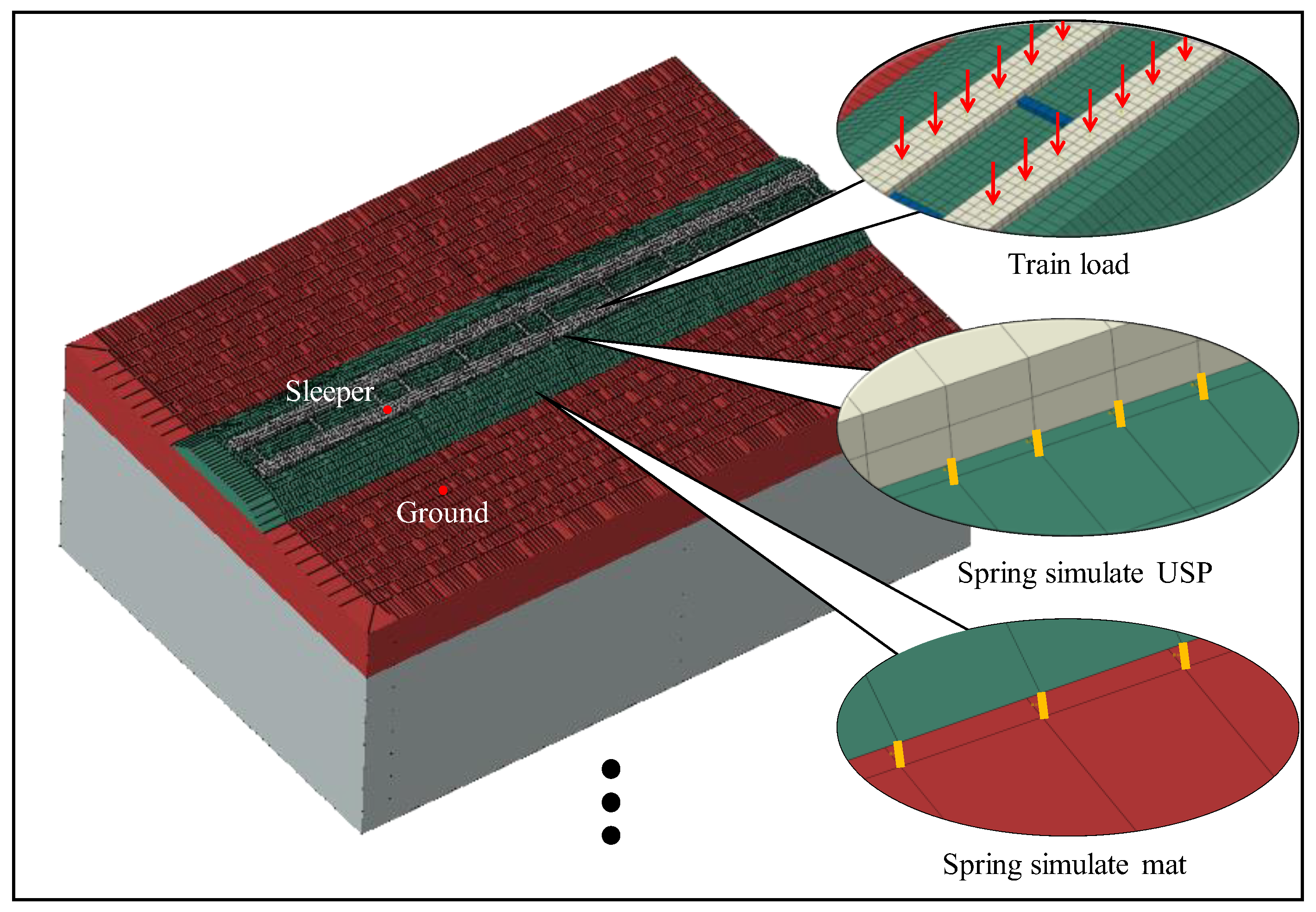
As illustrated in Figure 12, the USPs and UBMs were simulated by elastic spring elements. The train loads under each fastener obtained from SIMPACK-ABAQUS coupled analysis were applied on the sleepers. Because the rail and fastener have already been built in SIMPACK, the rail and fastener elements were not considered in the track-soil model.
The parameters of USPs and UBMs are listed in Table 5. The stiffness of USPs and UBMs was soft level which was more suitable for railway vibration control [13] From the data collected by the UIC (International Union of Railways), the soft level vertical stiffness of USPs is about 0.1 N/mm3 and the soft level vertical stiffness of UBMs is about 0.06 N/mm3. The elastic elements usually have a thickness of 15–30 mm [15]. So, the thickness of USPs and UBMs in this paper is 0.03 m.
5. Numerical Results and Discussion
5.1. Vibration Response under Train Loads
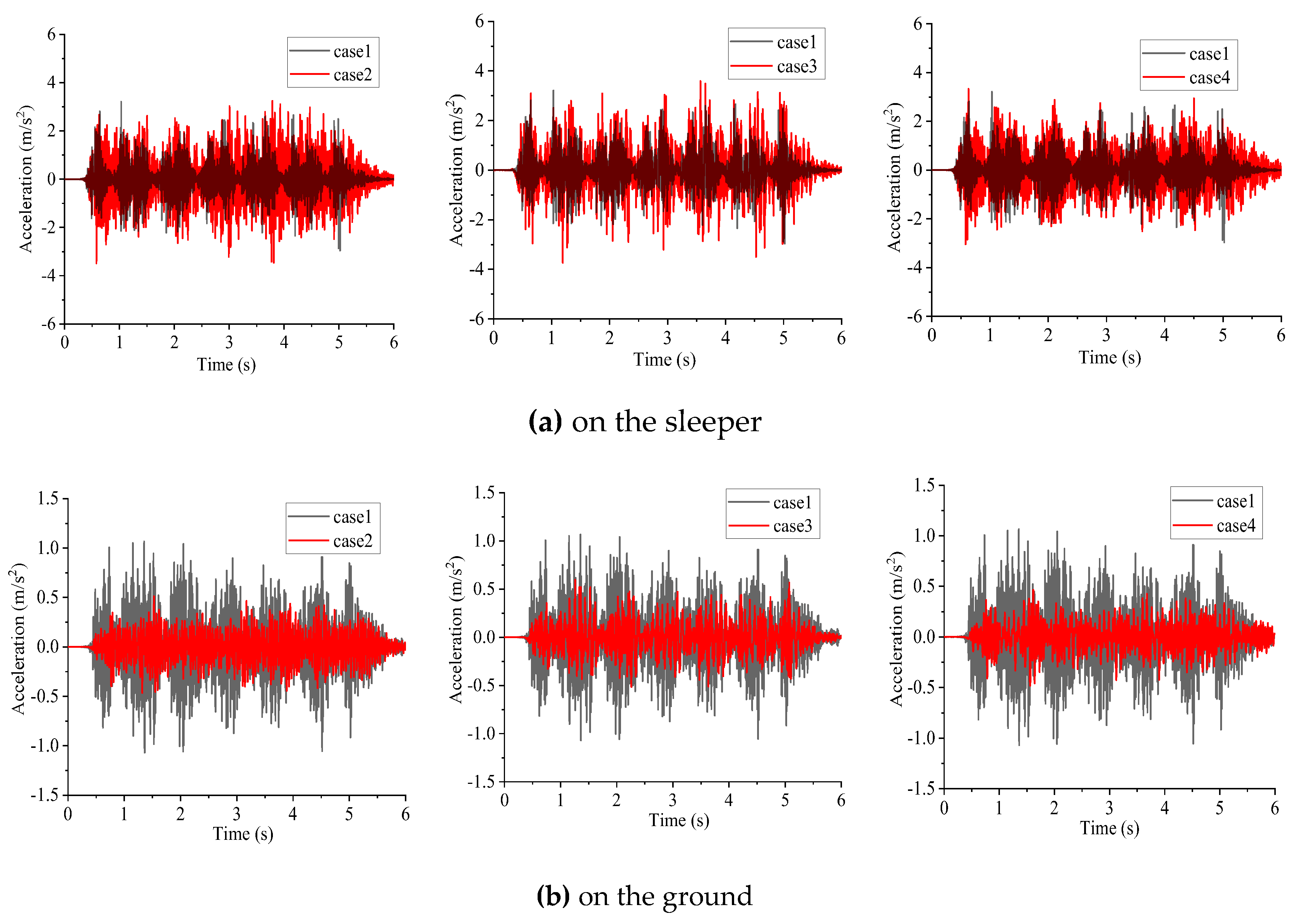
Figure 13 illustrated the time histories of ground vibrations of different cases. Obviously, on the sleeper, the acceleration amplitude values of case 2 and case 3 were larger than those of case 1. The USPs and UBMs can induce smaller acceleration peak values of ground accelerations in the time domain. Case 4 is the most effective case to control the train induced vibration.
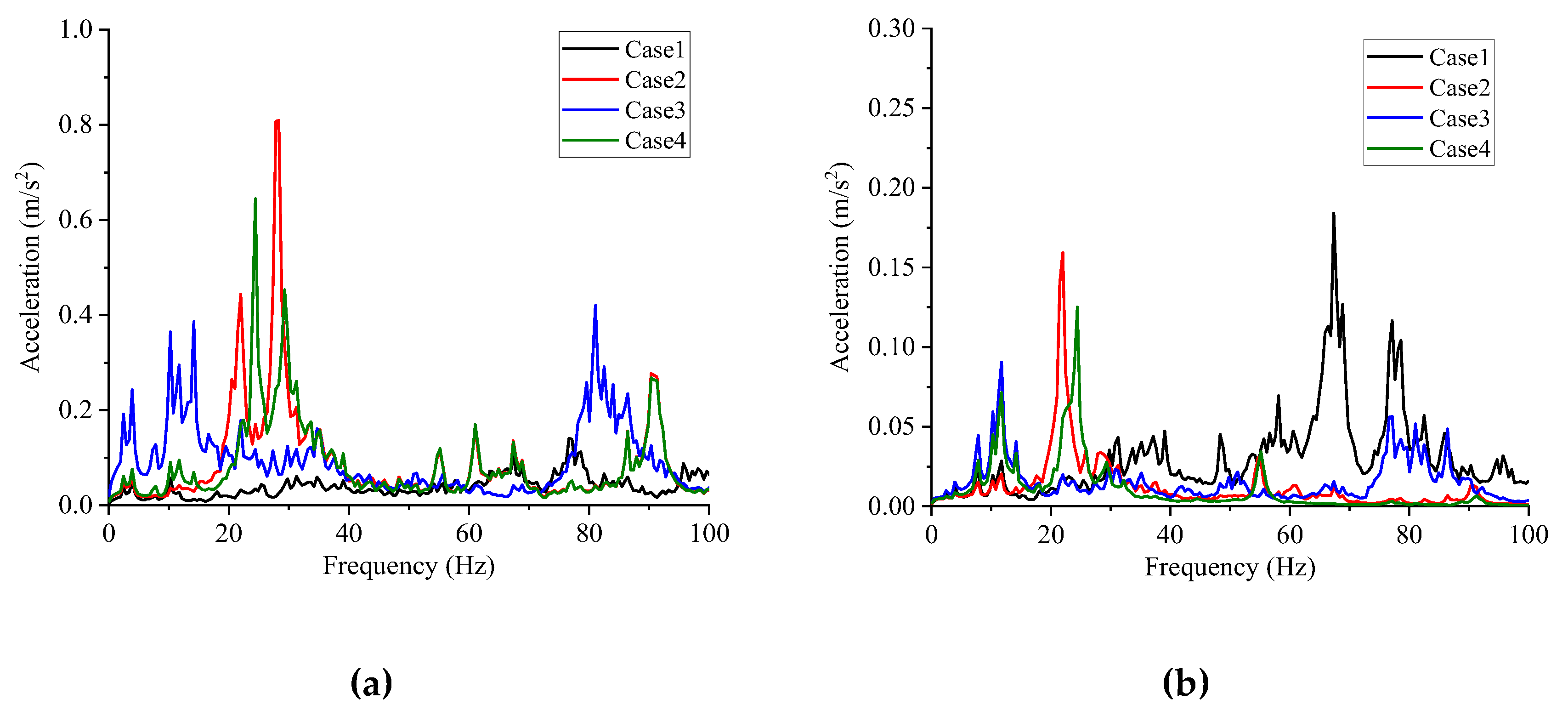
Figure 14 illustrates the acceleration responses of sleeper and ground in frequency domain. Peak values can be observed around 30 Hz in case 2 and case 4. Above 50 Hz, the vibration mitigation characteristics about all cases were obvious. Case 4 is the best. The principles of base isolation can explain this phenomenon by reference to a single-degree-of-freedom model where the track was represented by a mass and the elastic elements as spring-damper elements [14].
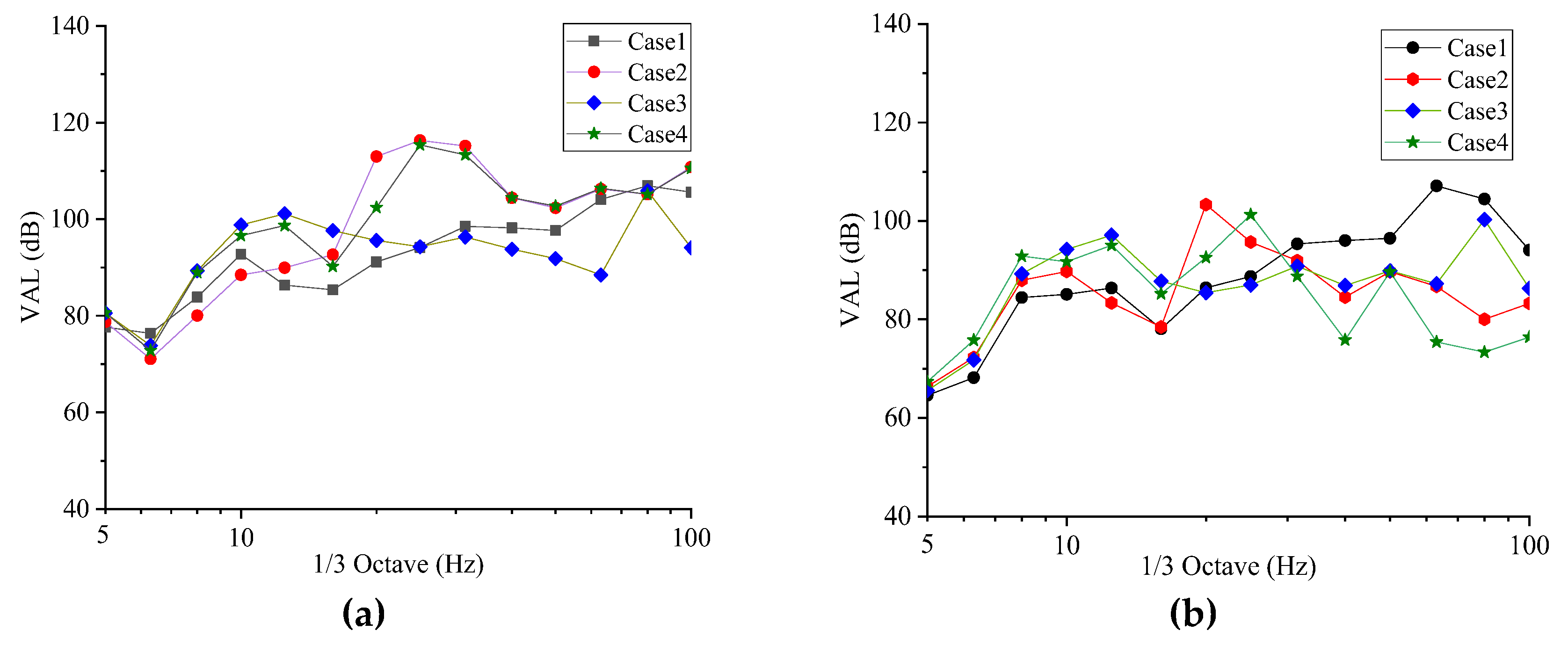
Figure 15 illustrates the vertical acceleration level (VAL) of sleeper and ground in all cases. On the sleeper, it can be observed that the case 2 could induce a high-level vibration response especially in approximately 30 Hz. On the ground, it can be observed the elastic elements can induce a vibration mitigation above 30 Hz. With both USPs and UBMs, vibration attenuated most above 50 Hz. The modals of the numerical models are also analysed. The calculated results are shown in Table 6.
From the results shown in Table 6, the phenomenon could be summarized that the peak values in Figure 14 are caused by the phugoid mode of the sleeper below 30 Hz. In sum, the model boundaries are affected by different elastic elements (USPs and UBMs), and then the vibration mitigation characteristics are also affected by the mode of the track system.
5.2. Evaluating the Effectiveness of Vibration Mitigation
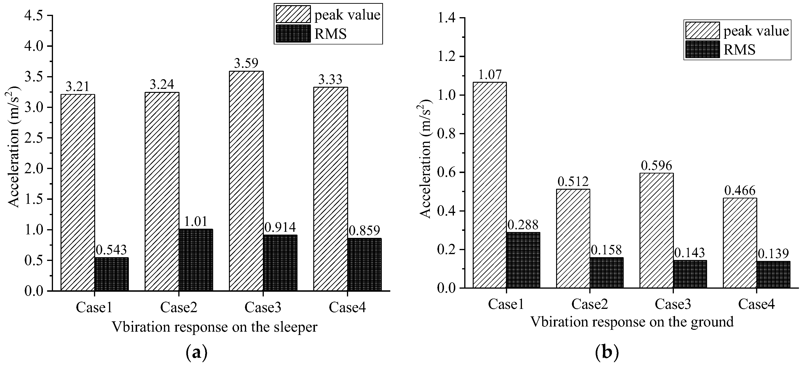
Figure 16 illustrates the peak and root-mean-square value (RMS) of four different cases. On the sleeper, the RMS value of case 2 is the largest one, corresponding values of the case 2, case 3 and case 1 successively decline. The peak value of case 3 is the largest value of all cases and the value of case 4 is the smallest one, but on the ground, the case 1 has the biggest value of peak and RMS.
The values of case 4 is smallest. It can be concluded that the ballasted ladder track with USPs & UBMs can provide the best vibration mitigation effectiveness. [35].
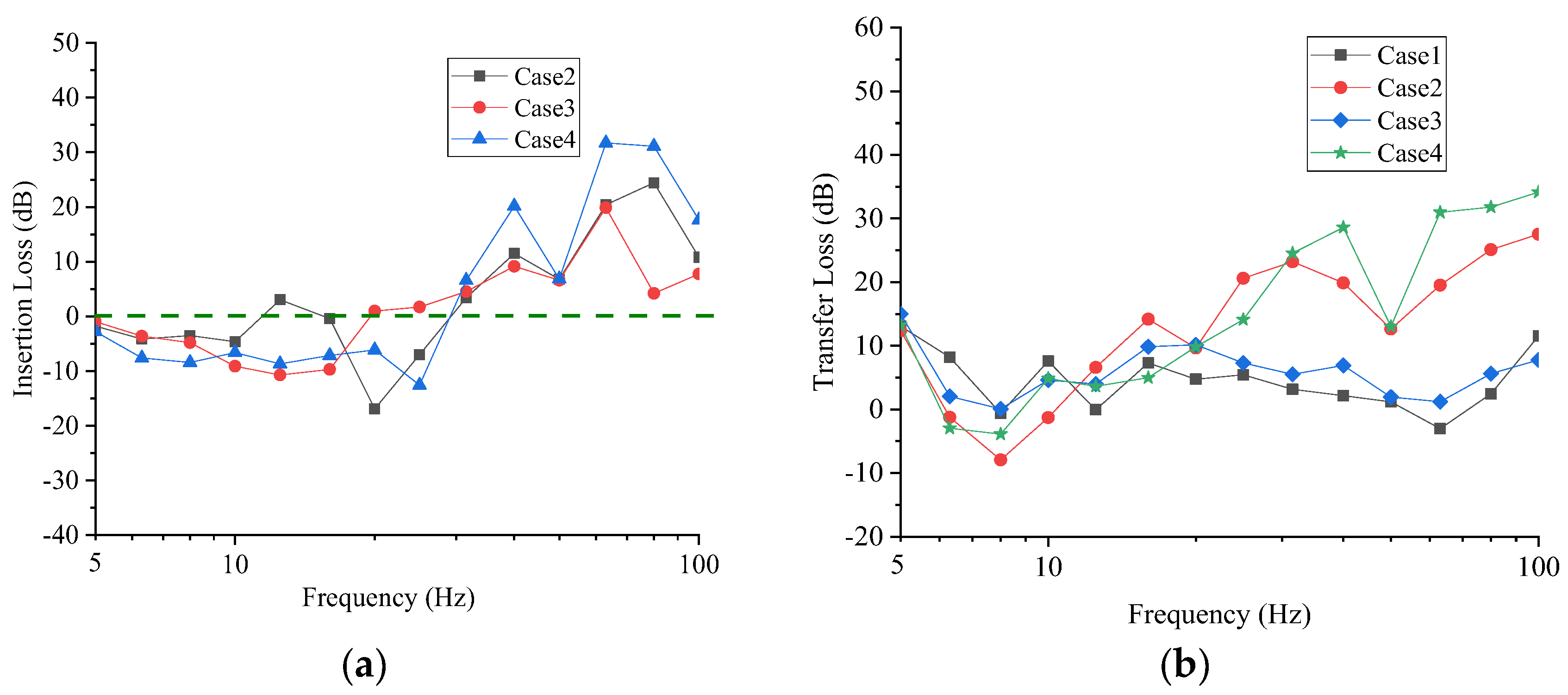
Figure 17 illustrates the insertion loss (IL) and TL for various applied elastic elements including USPs, UBMs, USPs&UBMs. The IL can be defined as:
where anon-insulated is the acceleration value of case 1 to be compared with aisolated, which is the acceleration value of case 2, 3 and 4.
It can be seen from Figure 17 that for cases 2, 3 and 4 the ILs were smaller than 0 between 5 and 30 Hz was and larger than 0 over 30 Hz. Case 4 works the best, but case 2 and case 3 work in different frequency bands. Figure 17b indicates that the TL of case 4 with an average value about 15 dB dissipated the most energy from the sleeper to ground, especially in the range of 50-100 Hz. Corresponding values of the Case 2 and case 3 successively decline.
By analysing various vibration reduction indicators, it can be found that there was a significant vibration mitigation effect above 50 Hz with the cases which have elastic elements, and about 15 dB of vibration mitigation effect. However, the phenomenon of vibration amplification occurs between 5 and 30 Hz. The more effective the vibration mitigation effects are in the range of more than 50 Hz, the more obvious the vibration amplification between 5 and 30 Hz is. Because the energy was conserved.
6. Conclusions
In the present work, both laboratory tests about the ballasted ladder track and numerical study on ballasted ladder track with elastic elements were performed. The following conclusions can be drawn:
- (1)
- The ballasted ladder track has advantages in controlling the low-frequency vibration. The test results show that a maximum vibration attenuation of 25.2 dB and an average vibration attenuation of 19.0 dB can be obtained between 5 and 20 Hz through the ballast.
- (2)
- The ballasted ladder track with elastic elements like USPs and UBMs can provide better vibration attenuation effect between 30 and 100 Hz. But below 30 Hz, the ballasted ladder track with elastic elements can produce greater vibration response.
- (3)
- Compared with the different elastic elements in ballasted ladder tracks, the case with USPs & UBMs can provide the best vibration mitigation effectiveness. The average value is about 15 dB and the peak value is about 30 dB between 30 and 100 Hz. But at about 20 Hz, the vibration was amplified by 15 dB.
- (4)
- The ballasted ladder track with elastic elements has effective vibration mitigation. While the ballast structure can control the vibration in the low frequency and the elastic elements such as USPs and UBMs can control the vibration in high frequency.
Accordingly, the ballasted ladder track with elastic elements has potential advantages in controlling freight train-induced vibration, which induces larger low-frequency vibrations. In addition, this work only focusses on the vibration mitigation effects of ballasted ladder track with USPs and UBMs. Further study should consider not only the vibration attenuation but also the safety and economic benefits of ballasted ladder track with elastic elements.
Author Contributions
Conceptualization, M.M.; Methodology, X.Q. and M.M.; Software, X.Q. and M.L.; Validation, M.M. and W.L.; Formal Analysis, X.Q. and M.M.; Investigation, X.Q., M.M. and M.L.; Resources, M.M., Y.C. and W.L; Data Curation, X.Q.; Writing—Original Draft Preparation, X.Q.; Writing—Review & Editing, M.M.; Visualization, X.Q. and M.L.; Supervision, M.M. and W.L.; Project Administration, M.M. and W.L.; Funding Acquisition, M.M. and W.L.
Funding
This research was funded by National Natural Science Foundation of China (Grant No. 51778049 and No. 51978043).
Conflicts of Interest
The authors declare no conflict of interest.
References
- Oyado, M.; Inoue, H.; Tottori, S. Longitudinal and lateral resistant characteristics of ladder sleeper. RTRI Rep. 1996, 10, 57–62. (In Japanese) [Google Scholar]
- Asanuma, K. Ladder Track Structure and Performance. Railw. Technol. Avalanche 2004, 6, 35. [Google Scholar]
- Wakui, H. Ladder sleepers perform well in tests. Railw. Gaz. Int. 1997, 159, 589–592. [Google Scholar]
- Younesian, D.; Mohammadzadeh, S.; Esmailzadeh, E. Dynamic performance, system identification and sensitivity analysis of the ladder tracks. In Proceedings of the 7th World Congress on Railway Research, Montreal, QC, Canada, 8 June 2006; pp. 104–110. [Google Scholar]
- Cargovibes Project Group. Attenuation of Ground-Borne Vibration Affecting Residents near Freight Railway Lines-Proposal Part B; TNO: Delft, The Netherlands, 2010. [Google Scholar]
- Ma, M.; Liu, W.N.; Li, Y.L.; Liu, W.F. An experimental study of vibration reduction of a ballasted ladder track. Proc. Inst. Mech. Eng. Part F J. Rail Rapid Transit 2017, 231, 1035–1047. [Google Scholar] [CrossRef]
- Watanabe, T.; Sogabe, M.; Wakui, H.; Shimabuku, J.; Shoji, M. Ground Vibration Characteristics of Ballasted Ladder Track. Procedia Eng. 2017, 199, 2741–2746. [Google Scholar] [CrossRef]
- Jing, G.Q.; Aela, P.; Fu, H. The contribution of ballast layer components to the lateral resistance of ladder sleeper track. Constr. Build. Mater. 2019, 202, 796–805. [Google Scholar] [CrossRef]
- Wei, K.; Wang, F.; Wang, P.; Liu, Z.X.; Zhang, P. Effect of temperature- and frequency-dependent dynamic properties of rail pads on high-speed vehicle–track coupled vibrations. Veh. Syst. Dyn. 2017, 55, 351–370. [Google Scholar] [CrossRef]
- Wei, K.; Wang, P.; Yang, F.; Xiao, J.H. Influence of Frequency-Dependent Dynamic Parameters of Rail Pads on Environmental Vibration Induced by Subways in a Tunnel. In Proceedings of the Transportation Research Board Meeting, Washington, DC, USA, 11–15 January 2015. [Google Scholar]
- Wei, K.; Wang, P.; Yang, F.; Xiao, J.H. The effect of the frequency-dependent stiffness of rail pad on the environment vibrations induced by subway train running in tunnel. Proc. Inst. Mech. Eng. Part F J. Rail Rapid Transit 2016, 230, 697–708. [Google Scholar] [CrossRef]
- Wei, K.; Wang, Q.; Dou, Y. Experimental investigation into temperature- and frequency-dependent dynamic properties of high-speed rail pads. Constr. Build. Mater. 2017, 151, 848–858. [Google Scholar] [CrossRef]
- Sol-Sánchez, M.; Moreno-Navarro, F.; Rubio-Gámez, M.C. The use of elastic elements in railway tracks: A state-of-the-art review. Constr. Build. Mater. 2015, 75, 293–305. [Google Scholar] [CrossRef]
- Thompson, D.J.; Kouroussis, G.; Ntotsios, E. Modelling, simulation and evaluation of ground vibration caused by rail vehicles. Veh. Syst. Dyn. 2019, 6, 1–48. [Google Scholar] [CrossRef]
- Costa, P.A.; Calçada, R.; Cardoso, A.S. Ballast mats for the reduction of railway traffic vibrations. Numerical study. Soil Dyn. Earthq. Eng. 2012, 42, 137–150. [Google Scholar] [CrossRef]
- Kraskiewicz, C.; Lipko, C.; Pludowska, M.; Oleksiewicz, W.; Zbiciak, A. Static and Dynamic Characteristics of Resilient Mats for Vibration Isolation of Railway Tracks. Procedia Eng. 2016, 153, 317–324. [Google Scholar] [CrossRef]
- Auersch, L. Dynamic axle loads on tracks with and without ballast mats: Numerical results of three-dimensional vehicle–track–soil models. Proc. Inst. Mech. Eng. Part F J. Rail Rapid Transit 2006, 220, 169–183. [Google Scholar] [CrossRef]
- Abadi, T.; Pen, L.L.; Zervos, A.; Powrie, W. Effect of Sleeper Interventions on Railway Track Performance. J. Geotech. Geoenviron. Eng. 2019, 145, 04019009. [Google Scholar] [CrossRef]
- Navaratnarajah, S.K.; Indraratna, B.; Ngo, N.T. Influence of under sleeper pads on ballast behavior under cyclic loading: Experimental and numerical studies. J. Geotech. Geoenviron. 2018, 144, 04018068. [Google Scholar] [CrossRef]
- Ngo, T.N.; Indraratna, B.; Rujikiatkamjorn, C. Improved performance of ballasted tracks under impact loading by recycled rubber mats. Transp. Geotech. 2019, 20, 100239. [Google Scholar] [CrossRef]
- Jayasuriya, C.; Indraratna, B.; Ngo, T.N. Experimental study to examine the role of under sleeper pads for improved performance of ballast under cyclic loading. Transp. Geotech. 2019, 19, 61–73. [Google Scholar] [CrossRef]
- Insa, R.; Salvador, P.; Inarejos, J.; Medina, L. Analysis of the performance of under-sleeper pads in high-speed line transition zones. Proc. Inst. Civ. Eng. Transp. 2014, 167, 63–77. [Google Scholar] [CrossRef]
- Li, H.; McDowell, G.R. Discrete element modelling of under sleeper pads using a box test. Granul. Matter 2018, 20, 26. [Google Scholar] [CrossRef]
- Paixão, A.; Varandas, J.N.; Fortunato, E.; Calçada, R. Numerical simulations to improve the use of under sleeper pads at transition zones to railway bridges. Eng. Struct. 2018, 164, 169–182. [Google Scholar] [CrossRef]
- Liang, L.; Li, X.; Yin, J.; Wang, D.; Gao, W.; Guo, Z. Vibration characteristics of damping pad floating slab on the long-span steel truss cable-stayed bridge in urban rail transit. Eng. Struct. 2019, 191, 92–103. [Google Scholar] [CrossRef]
- Yang, J.; Li, P.; Lu, Z. Numerical Simulation and In-Situ Measurement of Ground-Borne Vibration Due to Subway System. Sustainbility 2018, 10, 2439. [Google Scholar] [CrossRef]
- Li, L.; Nimbalkar, S.; Zhong, R. Finite element model of ballasted railway with infinite boundaries considering effects of moving train loads and Rayleigh waves. Soil Dyn. Earthq. Eng. 2018, 114, 147–153. [Google Scholar] [CrossRef]
- Alves Costa, P.; Lopes, P.; Silva Cardoso, A. Soil shakedown analysis of slab railway tracks: Numerical approach and parametric study. Transp. Geotech. 2018, 16, 85–96. [Google Scholar] [CrossRef]
- Xiao, H.; Gao, L.; Hou, B.W. Analysis of ballast dynamic behaviour with three-dimensional Discrete Element Method. J. Railw. Eng. Soc. 2009, 9, 14–17. (In Chinese) [Google Scholar]
- Huang, H.; Chrismer, S. Discrete element modelling of ballast settlement under train moving at “Critical Speeds”. Constr. Build. Mater. 2013, 38, 994–1000. [Google Scholar] [CrossRef]
- Galvín, P.; François, S.; Schevenels, M.; Bongini, E.; Degrande, G.; Lombaert, G. A 2.5 D coupled FE-BE model for the prediction of railway induced vibrations. Soil Dyn. Earthq. Eng. 2010, 30, 1500–1512. [Google Scholar] [CrossRef]
- Zhai, W.M.; Sun, X. A detailed model for investigating vertical interactions between railway vehicle and track. Veh. Syst. Dyn. 1994, 23, 603–615. [Google Scholar] [CrossRef]
- Lombaert, G.; Degrande, G.; Kogut, J.; François, S. The experimental validation of a numerical model for the prediction of railway induced vibrations. J. Sound Vib. 2006, 297, 512–535. [Google Scholar] [CrossRef]
- Ishihara, K. Soil Behaviour in Earthquake Geotechnics; Oxford Engineering Science Series; Clarendon Press: Oxford, UK, 1996. [Google Scholar]
- Zhai, W.; Wang, K.; Cai, C. Fundamentals of vehicle-track coupled dynamics. Veh. Syst. Dyn. 2009, 47, 1349–1376. [Google Scholar] [CrossRef]
- Ying, H.Q.; Shen, S.; Ying, M.; Liu, J.M. Impact Test Technique for Large-Scale Structure. In Proceedings of the Conference & Exposition on Structural Dynamics, Orlando, FL, USA, 16–18 April 2007; 2007. IMAC-XXV. [Google Scholar]
- Ji, Z.; Yang, G.; Liu, Y.; Jiang, Q. Analysis of vertical vibration characteristics of the vehicle-flexible track coupling system under wind load and track irregularity. Proc. Inst. Mech. Eng. Part F J. Rail Rapid Transit 2018, 232, 2444–2455. [Google Scholar] [CrossRef]
- Li, Y.; Xu, X.; Zhou, Y.; Cai, C.S.; Qin, J. An interactive method for the analysis of the simulation of vehicle-bridge coupling vibration using ANSYS and SIMPACK. Proc. Inst. Mech. Eng. Part F J. Rail Rapid Transit. 2018, 232, 663–679. [Google Scholar] [CrossRef]
- Ling, L.; Xiao, X.B.; Xiong, J.Y.; Zhou, L.; Wen, Z.F.; Jin, X.S. A 3D model for coupling dynamics analysis of high-speed train/track system. J. Zhejiang Univ. Sci. A 2014, 15, 964–983. [Google Scholar] [CrossRef]
- Guyan, R.J. Reduction of stiffness and mass matrices. AIAA J. 1965, 3, 380. [Google Scholar] [CrossRef]
- Kalker, J.J. On the Rolling Contact of Two Elastic Bodies in Presence of Dry Friction. Ph.D. Thesis, Delft University, Delft, The Netherland, 1967. [Google Scholar]
Figure 1.
Flowchart of train-track-soil numerical method.

Figure 2.
3D track-soil model in ABAQUS.

Figure 3.
Formation parameters: (a) S-wave velocity (b) P-wave velocity (c) density.

Figure 4.
The ballasted ladder tracks in the laboratory.

Figure 5.
Automatic falling weight system (a) Falling weight (b) Typical time history & spectrum of impulse forces.
Figure 5.
Automatic falling weight system (a) Falling weight (b) Typical time history & spectrum of impulse forces.

Figure 6.
Typical response time history of the ballasted ladder track.

Figure 7.
Dynamic results of test (a) VAL for the ballasted ladder track (b) TL through the ballast.
Figure 7.
Dynamic results of test (a) VAL for the ballasted ladder track (b) TL through the ballast.

Figure 8.
Model validation: (a) The location of the detection points (b) Tested and calculated TL results.
Figure 8.
Model validation: (a) The location of the detection points (b) Tested and calculated TL results.

Figure 9.
3D train-track model.

Figure 10.
Train-track model in SIMPACK (a) train model (b) FE model rail (c) rail and fastener in SIMPACK (d) FE model sleeper (e) sleeper in SIMPACK.
Figure 10.
Train-track model in SIMPACK (a) train model (b) FE model rail (c) rail and fastener in SIMPACK (d) FE model sleeper (e) sleeper in SIMPACK.

Figure 11.
Calculated (a) time history and (b) Fourier spectra of the train loads by SIMPACK.

Figure 12.
Track-soil model with case 4.

Figure 13.
Time history of the sleeper and ground vertical accelerations.

Figure 14.
Fourier Spectra of the vertical accelerations on the (a) sleeper (b) ground.

Figure 15.
Vertical acceleration level on the (a) sleeper (b) ground.

Figure 16.
Time-domain statistical indicators on the (a) sleeper (b) ground.

Figure 17.
Calculation results (a) IL of ground acceleration (b) TL of different types of track.


Table 1.
Main parameters of the numerical model.
| Structures | Parameter | Value |
|---|---|---|
| Rail (Rail mass per unit length is 60 kg/m) | Young modulus (N/m2) | 2.1 × 10¹¹ |
| Poisson’s ratio | 0.3 | |
| Density (kg/m3) | 7.85 × 10³ | |
| Damping factor α | 0.498 | |
| Damping factor β | 1.26 × 10⁻⁴ | |
| Fastener (spring elements) | Vertical stiffness (N/m) | 8 × 10⁷ |
| Vertical damping (Ns/m) | 7.5 × 10⁴ | |
| Ladder sleeper (finite elements) | Young modulus (N/m2) | 3.1 × 10¹⁰ |
| Poisson’s ratio | 0.3 | |
| Density (kg/m3) | 2.5 × 10³ | |
| Damping factor α | 0.622 | |
| Damping factor β | 1.58 × 10⁻⁴ | |
| P-wave velocity (m/s) | 4.08 × 10³ | |
| S-wave velocity (m/s) | 4.77 × 10⁶ | |
| Steel pipe (finite elements) | Young modulus (N/m2) | 2.1 × 10¹¹ |
| Poisson’s ratio | 0.3 | |
| Density (kg/m3) | 7.85 × 10³ | |
| Damping factor α | 0.498 | |
| Damping factor β | 1.26 × 10⁻⁴ | |
| Ballast (finite elements) | Young modulus (N/m2) | 2 × 10⁸ |
| Poisson’s ratio | 0.35 | |
| Density (kg/m3) | 1.6 × 10³ | |
| Damping factor α | 0.5 | |
| Damping factor β | 1.2 × 10⁻⁴ | |
| P-wave velocity (m/s) | 422 | |
| S-wave velocity (m/s) | 4.12 × 10⁴ |
Table 2.
Modal test results on ballasted ladder track
| No. of Order | Mode Shape | Natural Frequency | Damping Ratio |
|---|---|---|---|
| 1 |  | 60.6 Hz | 4.2% |
| 2 |  | 67.2 Hz | 3.8% |
| 3 |  | 69.3 Hz | 4.9% |
| 4 |  | 79.6 Hz | 7.9% |
| 5 |  | 82.7 Hz | 7.7% |
| 6 |  | 86.1 Hz | 3.4% |
Table 3.
Main parameters of the vehicle system.
| Parameters | Value |
|---|---|
| Carriage length (m) | 12.6 |
| Bogie length (m) | 2.3 |
| Wheel radius (m) | 0.42 |
| Car body mass (kg) | 4.3 × 10⁴ |
| Bogie mass (kg) | 3600 |
| Wheel mass (kg) | 1700 |
| Wheelbase (m) | 2.3 |
| Roll inertia of car body (kg×m2) | 2.21 × 10⁵ |
| Pitch inertia of car body (kg×m2) | 1.44 × 10⁶ |
| Yaw inertia of car body (kg×m2) | 1.28 × 10⁶ |
| Roll inertia of bogie (kg×m2) | 1206 |
| Pitch inertia of bogie (kg×m2) | 1736 |
| Yaw inertia of bogie (kg×m2) | 2809 |
| Roll inertia of wheel (kg×m2) | 706 |
| Pitch inertia of wheel (kg×m2) | 109 |
| Yaw inertia of wheel (kg×m2) | 716 |
| Longitudinal primary suspension stiffness (N/m) | 1.52 × 10⁶ |
| Lateral primary suspension stiffness (N/m) | 1.52 × 10⁶ |
| Vertical primary suspension stiffness (N/m) | 1.52 × 10⁶ |
| Longitudinal secondary suspension stiffness (N/m) | 1.49 × 10⁵ |
| Lateral secondary suspension stiffness (N/m) | 1.49 × 10⁵ |
| Vertical secondary suspension stiffness (N/m) | 4.35 × 10⁵ |
| Longitudinal primary suspension damping (Ns/m) | 4 × 10⁴ |
| Lateral primary suspension damping (Ns/m) | 4 × 10⁴ |
| Vertical primary suspension damping (Ns/m) | 5 × 10⁴ |
| Longitudinal secondary suspension damping (Ns/m) | 5 × 10⁴ |
| Lateral secondary suspension damping (Ns/m) | 5 × 10⁴ |
| Vertical secondary suspension damping (Ns/m) | 6 × 10⁴ |
Table 4.
Numerical cases.
| Case | Elastic Element | Sketch |
|---|---|---|
| 1 | Without |  |
| 2 | USPs |  |
| 3 | UBMs |  |
| 4 | USPs and UBMs |  |
Table 5.
Parameters of USPs and UBMs.
| Structures | Parameter | Value |
|---|---|---|
| USPs | Vertical stiffness (N/mm3) | 0.1 |
| Thickness (m) | 0.03 | |
| UBMs | Vertical stiffness (N/mm3) | 0.06 |
| Thickness (m) | 0.03 |
Table 6.
Modal analysis of cases 2, 3, 4.
| No. of Order | Mode Shape (Case 2) | Natural Frequency | Mode Shape (Case 3) | Natural Frequency | Mode Shape (Case 4) | Natural Frequency |
|---|---|---|---|---|---|---|
| 1 |  | 24.965 Hz |  | 9.815 Hz |  | 21.991 Hz |
| 2 |  | 35.386 Hz |  | 15.908 Hz |  | 22.074 Hz |
| 3 |  | 35.840 Hz |  | 16.297 Hz |  | 22.421 Hz |
| 4 |  | 38.788 Hz |  | 18.457 Hz |  | 23.047 Hz |
| 5 |  | 42.891 Hz |  | 19.368 Hz |  | 25.647 Hz |
| 6 |  | 52.612 Hz |  | 20.282 Hz |  | 25.699 Hz |
© 2019 by the authors. Licensee MDPI, Basel, Switzerland. This article is an open access article distributed under the terms and conditions of the Creative Commons Attribution (CC BY) license (http://creativecommons.org/licenses/by/4.0/).
Share and Cite
MDPI and ACS Style
Qu, X.; Ma, M.; Li, M.; Cao, Y.; Liu, W. Analysis of the Vibration Mitigation Characteristics of the Ballasted Ladder Track with Elastic Elements. Sustainability 2019, 11, 6780. https://0-doi-org.brum.beds.ac.uk/10.3390/su11236780
AMA Style
Qu X, Ma M, Li M, Cao Y, Liu W. Analysis of the Vibration Mitigation Characteristics of the Ballasted Ladder Track with Elastic Elements. Sustainability. 2019; 11(23):6780. https://0-doi-org.brum.beds.ac.uk/10.3390/su11236780
Chicago/Turabian StyleQu, Xiangyu, Meng Ma, Minghang Li, Yanmei Cao, and Weining Liu. 2019. "Analysis of the Vibration Mitigation Characteristics of the Ballasted Ladder Track with Elastic Elements" Sustainability 11, no. 23: 6780. https://0-doi-org.brum.beds.ac.uk/10.3390/su11236780
Note that from the first issue of 2016, this journal uses article numbers instead of page numbers. See further details here.