Process Design Characteristics of Syngas (CO/H2) Separation Using Composite Membrane


Department of Environmental Engineering, Kongju National University, 1223-24 Cheonan-Daero, Seobuk, Chungnam 31080, Korea
*
Author to whom correspondence should be addressed.
Sustainability 2019, 11(3), 703; https://0-doi-org.brum.beds.ac.uk/10.3390/su11030703
Submission received: 24 December 2018
/
Revised: 22 January 2019
/
Accepted: 28 January 2019
/
Published: 29 January 2019
(This article belongs to the Special Issue Emerging Technologies and Solutions for the Sustainable Climate Change Challenges)
Abstract
:The effectiveness of gas separation membranes and their application is continually growing owing to its simpler separation methods. In addition, their application is increasing for the separation of syngas (CO and H2) which utilizes cryogenic temperature during separation. Polymers are widely used as membrane material for performing the separation of various gaseous mixtures due to their attractive perm-selective properties and high processability. This study, therefore, aims to investigate the process design characteristics of syngas separation utilizing polyamide composite membrane with polyimide support. Moreover, characteristics of CO/H2 separation were investigated by varying inlet gas flow rates, stage cut, inlet gas pressures, and membrane module temperature. Beneficial impact in CO and H2 purity were obtained on increasing the flow rate with no significant effect of increasing membrane module temperature and approximately 97% pure CO was obtained from the third stage of the multi-stage membrane system.
1. Introduction
In recent years, there have been tremendous advancements in the fields of industry, service, and commerce. Although this growth has brought substantial economic and social benefits, such as improving people’s lives, it has also provoked numerous side effects. Municipal solid waste (MSW) is one of the crucial problems that is of major concern globally. The quantity of MSW is rising significantly in industrialized and developing countries bringing into question its sustainable disposal management [1,2,3]. The desire to protect the environment has resulted in the development of various ideas for the legitimate management of MSW. For instance, technologies, such as incineration, gasification, generation of biogas, and utilization in a combined heat and power (CHP) plants, have been investigated for the production of energy from MSW [4,5]. In spite of the advantages derived from incineration of MSW, such as heat recovery, there are numerous disadvantages associated with the production of large flue gas volumes and hazardous waste streams accompanying the fly ash. However, gasification is an attractive way to treat MSW with fewer pollution emissions in contrast to other treatment methods and offers better competency in terms of energy production [6].
The major components obtained from gasification of waste are CO, H2, CO2, N2, and CH4 although the higher percentage is constituted by CO, CO2, and H2. CO2 from natural gas and post-combustion can be removed through effective and low-cost absorption processes comprising chemical solvents [7]. Among various processes, adsorption technology holds the potential to effectively separate CO2 due to its increased flexibility to adapt to varying feed stream specifications and operating conditions along with its simplicity, lower energy requirement, and low cost [8]. CH4 and N2 are present in an insignificant amount and can be removed through appropriate control of the operating conditions. Moreover, CH4 and N2 can be removed through layered pressure swing adsorption (PSA) as reviewed by Simone et al. [9]. Synthesis gas (syngas) is a mixture of H2 and CO which is used in diverse petrochemical processes and can be obtained after separating CO2. It can be used as a mixture or can be separated into its constituents before use [10]. State-of-the-art shows that the most efficient method for production of syngas is the reforming processes [11]. Thus, one of the aims of this study is to highlight the syngas produced from MSW gasification. In addition, the separation and purification of carbon monoxide are of great significance with respect to its importance as the starting material for the synthesis of a variety of basic chemicals in C1 chemistry processes [12] and capitalize on H2 as a source of fuel. However, the separation of gases by the membrane is one of the most flexible separation processes. Amongst many available techniques, such as distillation, crystallization, absorption, or solvent extraction for chemical separations, membrane technology is economically competitive for administering alternative separation technologies [11,13]. Opportunities thrive to extend membrane markets for gas separations although the existing membrane materials, membrane structures, and formation processes are inadequate for thorough utilization of these opportunities, and the requirements for the viability of membranes vary considerably with each application [14]. PSA and Cryogenic distillation processes are commercially available separation techniques among which cryogenic distillation is energy intensive [9,15,16]. The high operating costs associated with low productivity are the main disadvantages of adsorption separation method, such as PSA [10]. The interest on membrane technology continues to grow as the membrane process equipment, and methods of operation are comparatively easy compared to conventional separation methods. This is especially true for the separation of gaseous mixtures, such as CO and H2, which require cryogenic temperatures when separated by condensation, distillation, or adsorption [17]. Lu et al. [18] utilized inorganic membranes for hydrogen production and purification. References [19,20] portray the benefits of palladium and Pd-alloy membranes as an excellent means of hydrogen purification, especially while merging a catalytic reactor and separation in a single unit. However, the application of dense polymeric membrane dominates the gas separation field where the separation of gases with similar particle size can be obtained through diffusion if a variation in solubility exists [21]. Nevertheless, the polymeric membrane still needs further research due to “upper bound” where the membranes result in lower selectivity due to its open structure [22,23]. Even though selective permeation exhibits great potential for the separation of gases, it was not economically feasible due to the large membrane surface areas required to carry out industrial-scale separation. Considering the trade-off relation between cost and efficiency in selecting the membranes, this study utilizes the rubbery composite membrane with braid to provide mechanical strength to the membrane.
Along with the development of new and efficient membrane materials with enhanced gas separation efficiencies, process design is also indispensable as it directly affects the economics of membrane-based separation processes. The application of a rubbery composite membrane was carried out to separate two main components of syngas (CO and H2) obtained from MSW gasification as the working pressure was low and the cost associated with the membrane is comparatively lower than specific metallic membrane for hydrogen gas permeation. The manufacturing and commercialization of other inorganic materials are still expensive compared to polymeric membranes although inorganic membranes demonstrate higher performance [24]. The composite polyamide membrane with polyimide support was used to enhance the mechanical strength of the membrane. Characteristic analysis of syngas separation using gas membrane through CO/H2 permeability and selectivity was conducted along with a detailed study of multistage membrane design. Characteristic analysis of syngas separation using gas membrane through CO/H2 permeability and selectivity was conducted along with a detailed study of multistage membrane design. Multistage membrane design is of great importance while obtaining syngas of varying composition, and a high purity level is one of the novel achievements of this study. The comprehensive characteristic analysis was determined using various gas flow rate, stage cut, membrane-module temperature, and input pressure. The polyamide composite membrane with polyimide support has not been studied which further highlights the possibility of incorporating polyamide (rubbery polymer) with polyimide (glassy polymer) to obtain better separation efficiency.
2. Experimental
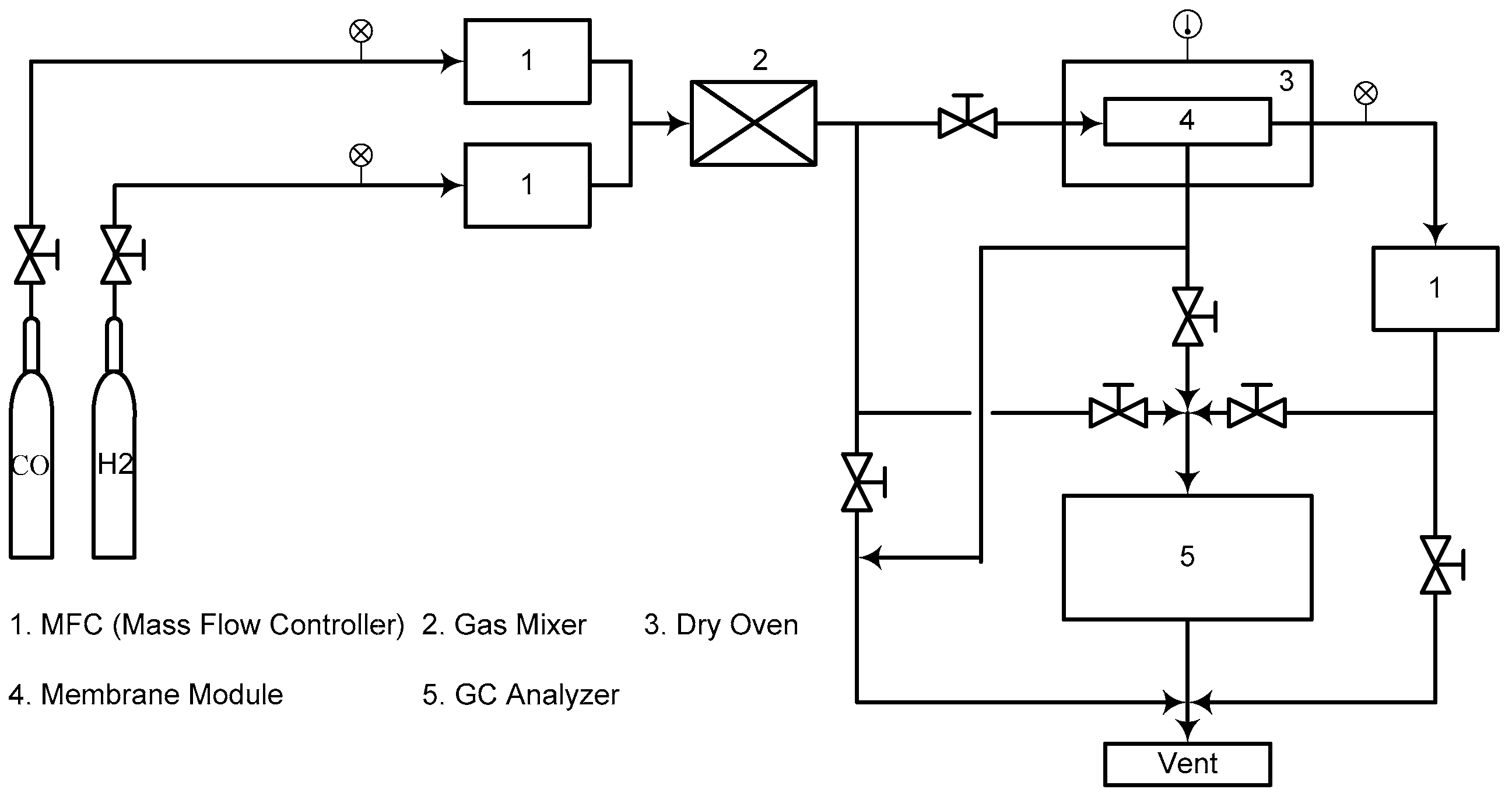
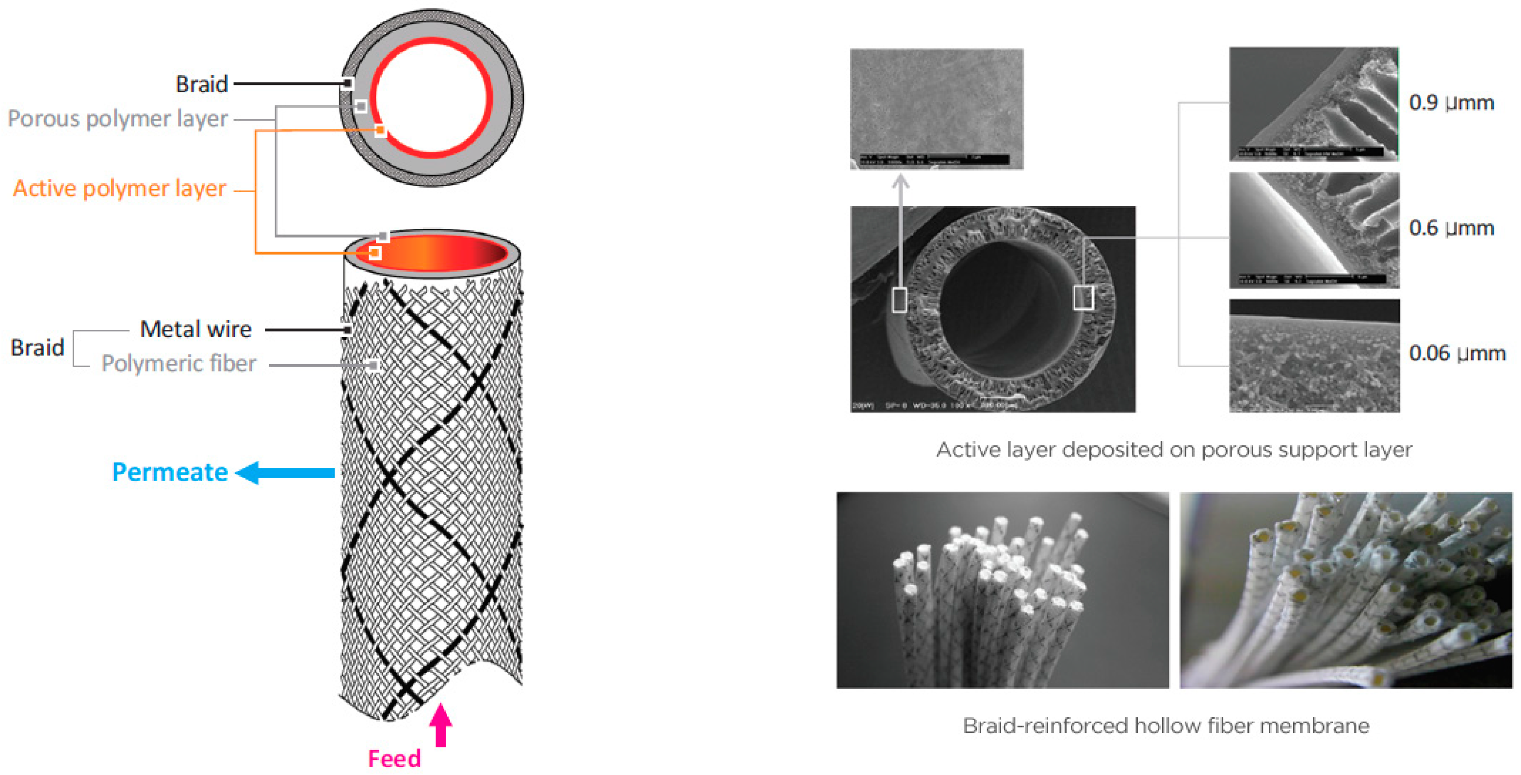
A polyamide composite membrane with polyimide support was used in this experiment. The membrane module was manufactured by SepraTek Co. (Republic of Korea). The schematic diagram of the overall membrane system used in this work and the specific features of the membrane are illustrated in Figure 1. It also demonstrates the SEM image of the outer surface and the active membrane layer where the inner polyamide membrane (active layer) is supported by the polyimide layer (middle layer). The outermost layer is the braid that provides support and strength to the membrane which comprises metallic wires and polymer fibers. The outermost layer is braided providing support and strength to the membrane and is made of a high strength polyester fiber, the porous intermediate substrate is of polyetherimide, and the active inner layer is of rubbery polyamide. The rubbery active layer has a dense structure. The integration of an individual braid-reinforced hollow fiber membrane aided to establish the complete membrane as demonstrated in Figure 2. The outer diameter of the final membrane is 7 cm with an inner surface area of 0.55 m2.
The pseudo syngas mixed from CO with purity of 99.95 vol% and H2 with purity of 99.999 vol% was used in this study. The composition of pseudo syngas was controlled by adjusting inlet flow rates of CO and H2 using mass flow controller (MFC). The CO and H2 gases from cylinders are uniformly mixed in a gas mixer and injected into membrane module. The gas inlet pressure was also controlled by the gas regulator connected to the gas cylinders. The stage cut was controlled by adjusting the flow rate of retentate using MFC, and the permeate pressure was atmospheric. To analyze the composition of gases, each gas flow line was connected to gas chromatography (GC) analyzer (i GC 7200, DS SCIENCE, Republic of Korea). Six foot by an eighth of an inch stainless steel packed column with 80/100 mesh molecular sieve 5A as column material was used in the GC analyzer. Argon (25 mL/min) was used as the carrier gas with a column temperature of 130 °C at a heating rate of 10 °C/min. The detector temperature was set at 130 °C/min. The kinetic diameter of CO and H2 was 3.6 and 2.9 Å, respectively [25] due to which H2 was obtained as permeate and CO as retentate. Furthermore, cumulative data of CO separation characteristics at various CO:H2 concentrations were studied to estimate the multistage membrane number required to obtain varying CO purity.
The permeability is related to the gas permeation rate through the membrane, the surface area of the membrane, and the pressure difference across the membrane and is expressed as:
where, PH2 and PCO are the permeability (cm3 cm−2 s−1 cm Hg−1) of H2 and CO, respectively, and QH2 and QCO are the flow rate (cm3 s−1) of H2 and CO, respectively. In addition, in Equation (1), A denotes the surface area (cm2) of the membrane, and ΔP is pressure difference (cm Hg) between retentate and permeate. The selectivity of H2 in permeate is defined as
In this work, the permeability of each gas was calculated by Equations (1) and (2). And the selectivity of H2 in permeate was calculated by Equation (3). Furthermore, the stage cut (%) used in this work was calculated as follows:
where, QR and QF are the flow rate (cm3 s−1) of retentate and feed gas, respectively.
3. Results and Discussions
3.1. Effect of Varying Gas Flow Rate for Various Stage Cut
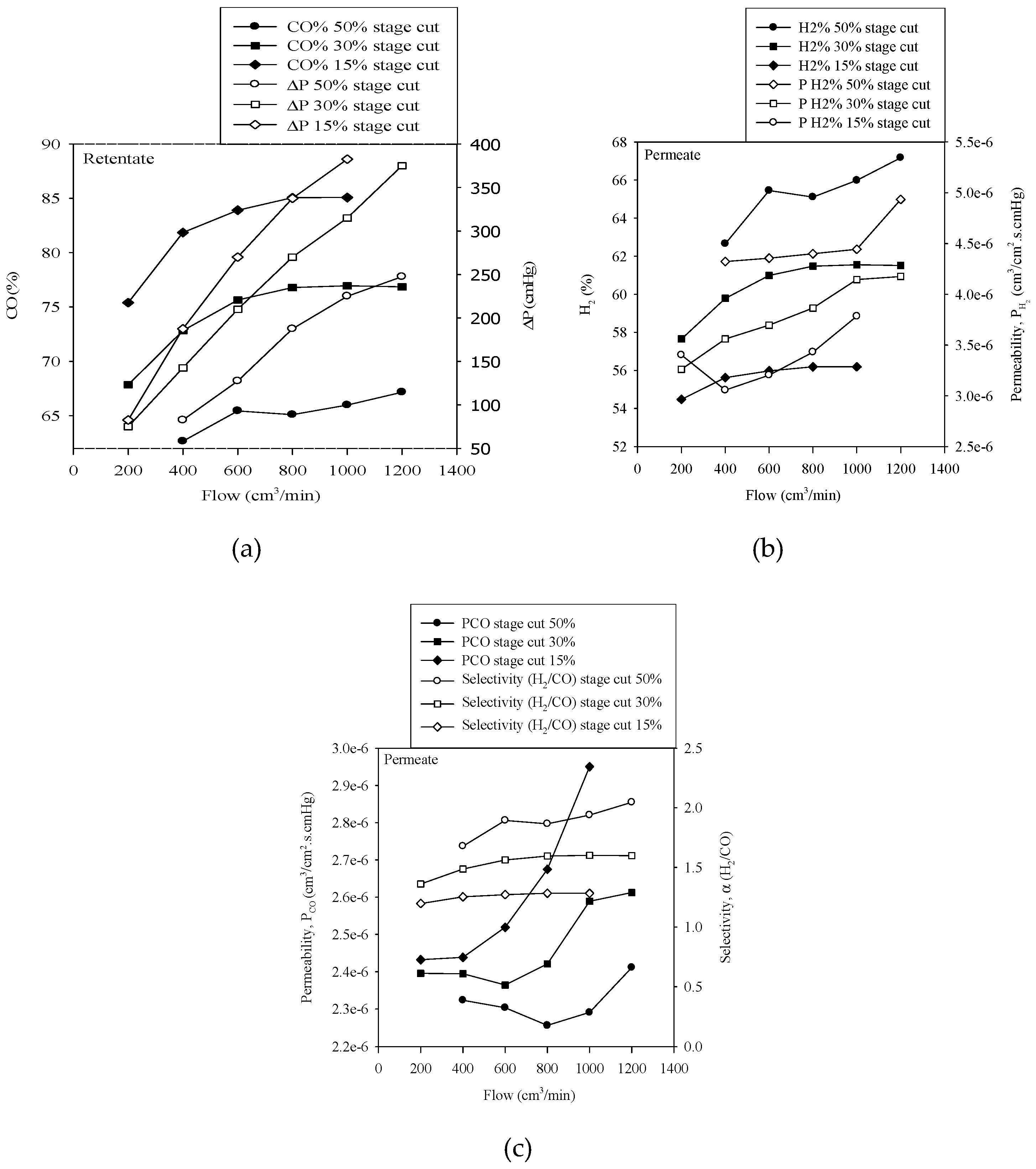
The characteristics of CO/H2 separation for various stage cut (15, 30, and 50%) with an increase in flow rate of the input gas at 6 bars inlet pressure is exhibited in Figure 3a–c. The actual working pressure (the gauge pressure of the membrane) was much lower in comparison to the inlet gas pressure and was maintained by controlling the stage cut. The stage cut is directly related to the recovery percentage and the economic feasibility of the process, thereby, making it one of the most important parameters while selecting membrane technology. From the figure, it can be observed that the working pressure of the membrane, which is the pressure difference, increased with a decrease in the stage cut, thereby, increasing the actual driving pressure of the membrane. A decrease in the stage cut reduced the free flow of gas through the retentate which increases the pressure inside the membrane volume. In addition, the CO purity was elevated while the H2 purity deteriorated with the lowering of the stage cut and vice versa. The decrease in the stage cut relates to the increase in driving pressure which tends to push the gas mixture more towards permeate forcing more CO to pass through the permeate. This increases the purity of CO in the retentate while the passage of CO in permeate decreases the purity of H2. A gradual increase in the input flow rate increases the CO and H2 purity which further is affected by the stage cut.
In addition, the permeability of H2 and CO increased with an increase in flow rate which is directly correlated with the amount of gas. The permeability of H2 was higher while permeability of CO was lower for increased stage cut. An increase in the stage cut permitted the natural flow of CO towards retentate and H2 towards permeate. However, a reduction in the stage cut increased the working pressures, thus, forcing CO towards permeate increasing CO permeability. Initially, on increasing the gas flow rate, the separation efficiency of the membrane increased with an increase in working pressure. On further increasing the flow rate, CO was forced to pass through permeate thereby increasing the CO permeability. However, the increase in CO permeability reduced the CO/H2 separation efficiency. Nevertheless, the purity of CO can be increased although the separation efficiency is reduced. However, reduction in the stage cut reduces the recovery while reducing the economic feasibility. The selectivity of the membrane for H2 as it is the target product of permeate slightly increases with the increase in flow rate and decreases with a decrease in the stage cut.
3.2. Effect of Varying Gas Flow Rate for Various Gas Inlet Pressures
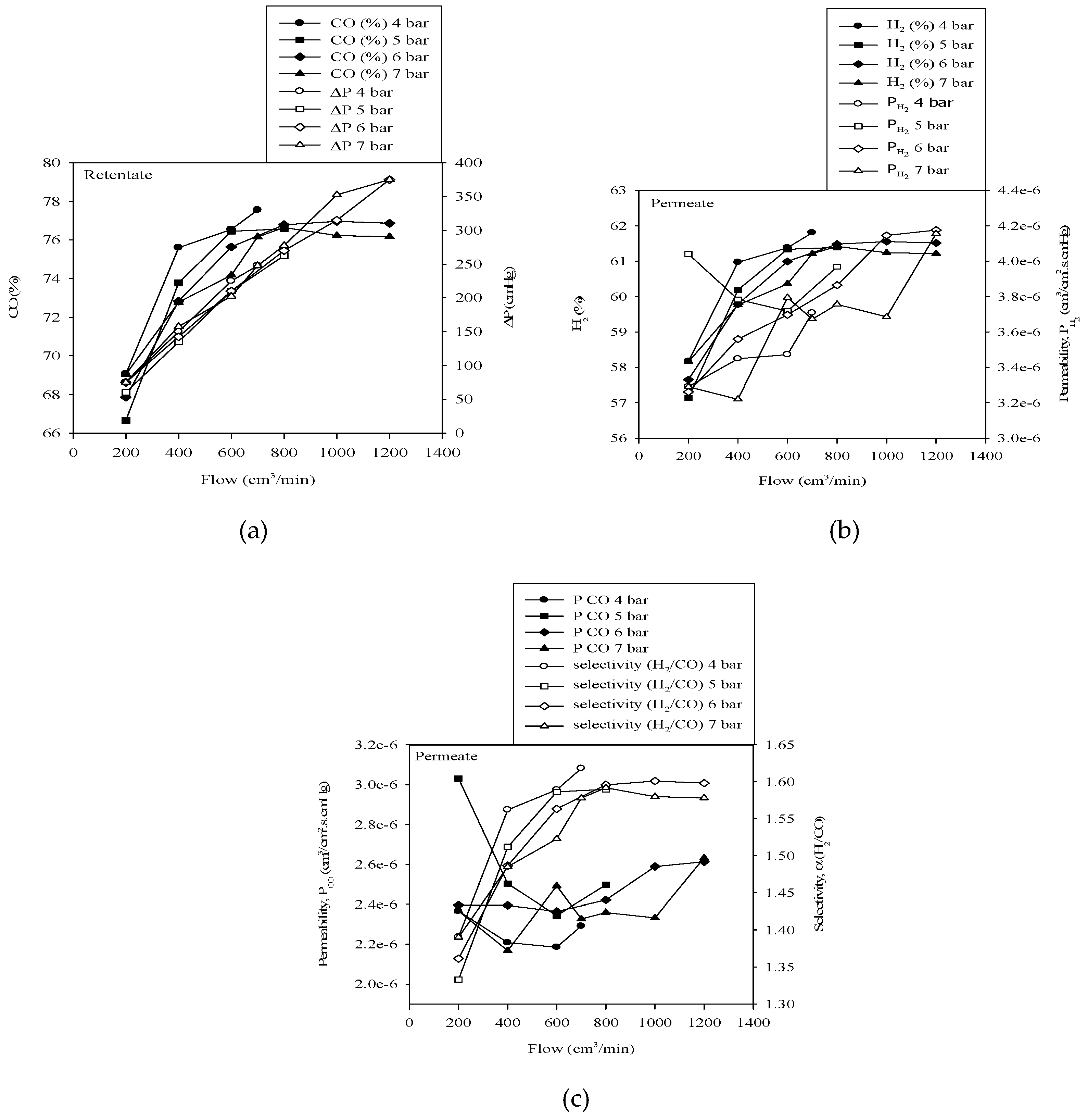
The characteristics of CO/H2 separation at various inlet pressures with an increase in inlet gas flow rate are shown in Figure 4a–c. Although the trend obtained for an increase in flow rate is similar to the discussion in Section 3.1 for gas flow rate, the characteristics were not significantly affected by the variation in gas inlet pressure. CO and H2 purity along with H2 selectivity somewhat reduced with an increase in inlet pressure thereby resulting in the forced passage of CO in permeate and H2 in the retentate. However, the pressure difference, which is the primary driving force of the membrane, was not affected at all by the change in the inlet pressure. Therefore, the characteristics are indifferent to the variation in inlet gas pressure. Furthermore, CO and H2 permeability failed to depict a particular trend with variation in gas inlet pressure. The presence of a mixer for homogeneous mixing of the inlet gases before entering the membrane as shown in Figure 1 significantly reduced the effect of inlet gas pressure.
3.3. Effect of Varying the Stage Cut for Various Gas Flow Rate
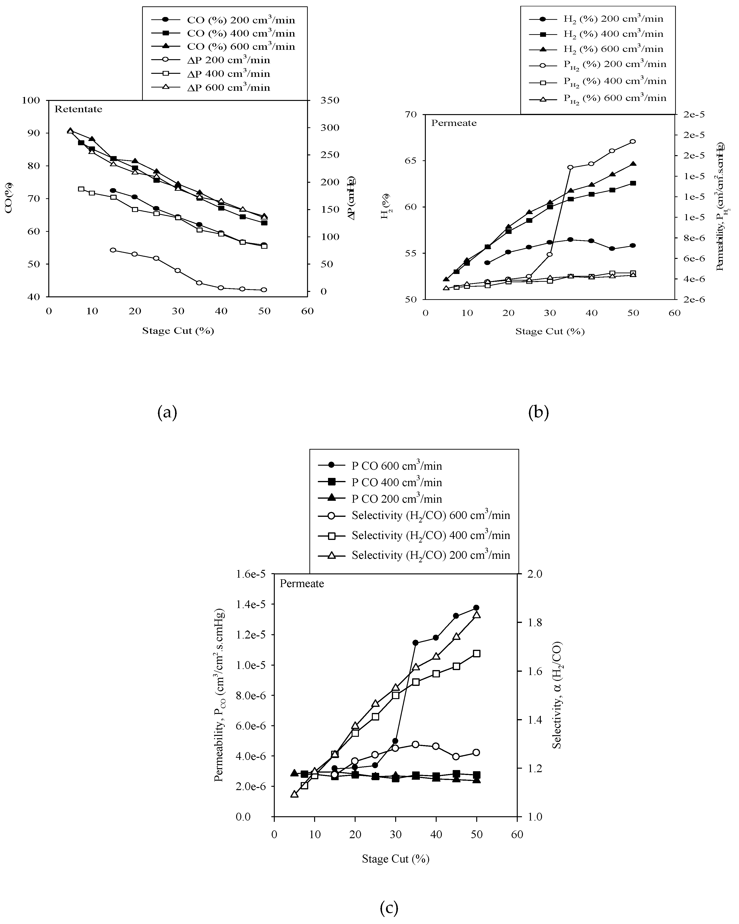
The effect of varying the stage cut for various gas flow rates is shown in Figure 5a–c. The increase in the stage cut refers to the increase in the gas flow amount from the retentate as described by Equation (4). CO purity and the pressure difference gradually dropped with an increase in the stage cut. On varying the gas flow rate, a notable difference was obtained for 200 and 400 cm3/min while the difference was insignificant for 400 and 600 cm3/min. An increase in the stage cut reduced the working pressure thereby forcing H2 to pass through the retentate and reducing CO purity. However, the reduction of working pressure significantly increased the H2 purity in the permeate. The permeability of H2 did not vary for 400 and 600 cm3/min which however increased after 25% stage cut. Oana et al. [26] also demonstrated a gradual increase in the permeability of H2 on increasing the gas flow rate to 6 cm3(STP)/min at 30 °C and 4 bar feed pressure. However, on further increasing the flow rate, the H2 permeability remained constant. Very low working pressure at this point resulted in a very low flow of CO in permeate thereby increasing H2 permeability. Contrarily, the CO permeability is not affected by the increase in the stage cut for 200 and 400 cm3/min while the CO permeability increased after 25% stage cut for 600 cm3/min. This is due to the volume of the membrane which after certain point forces the air to pass through the permeate as the driving pressure was highest for 600 cm3/min. H2 selectivity was lowest for 600 cm3/min while highest for 200 cm3/min as this is directly related to the permeability of H2 and CO as shown in Equation (3). Highest permeability of CO at 600 cm3/min resulted in the lowest selectivity of H2 at this point.
3.4. Effect of Varying Membrane Module Temperature
In dense polymeric materials, solution–diffusion is widely accepted to be the main mechanism of transport [27]. This mechanism is generally considered to be a three-step process. In the first step, the gas molecules are absorbed by the membrane surface in the upstream end. This is followed by the diffusion of the gas molecules through the polymer matrix. In the final step, the gas molecules are desorbed to the downstream end [28]. Thus, the permeability of gas in the polymer membrane system is affected by temperature. Furthermore, the small size of the hydrogen molecules gives H2 its high diffusivity [29] while the low temperature suggests that the solubility of hydrogen is very low [30,31]. Therefore, the goal of the process design is to exploit the high diffusivity of the hydrogen molecule and limit the effect of the lower solubility. Usually, with an increase in module temperature, diffusivity, depending on the free volume, increases which in turn decreases the solubility. However, correlations showing the separate effects of diffusion and solubility coefficients on selectivity and permeability are more limited [32].
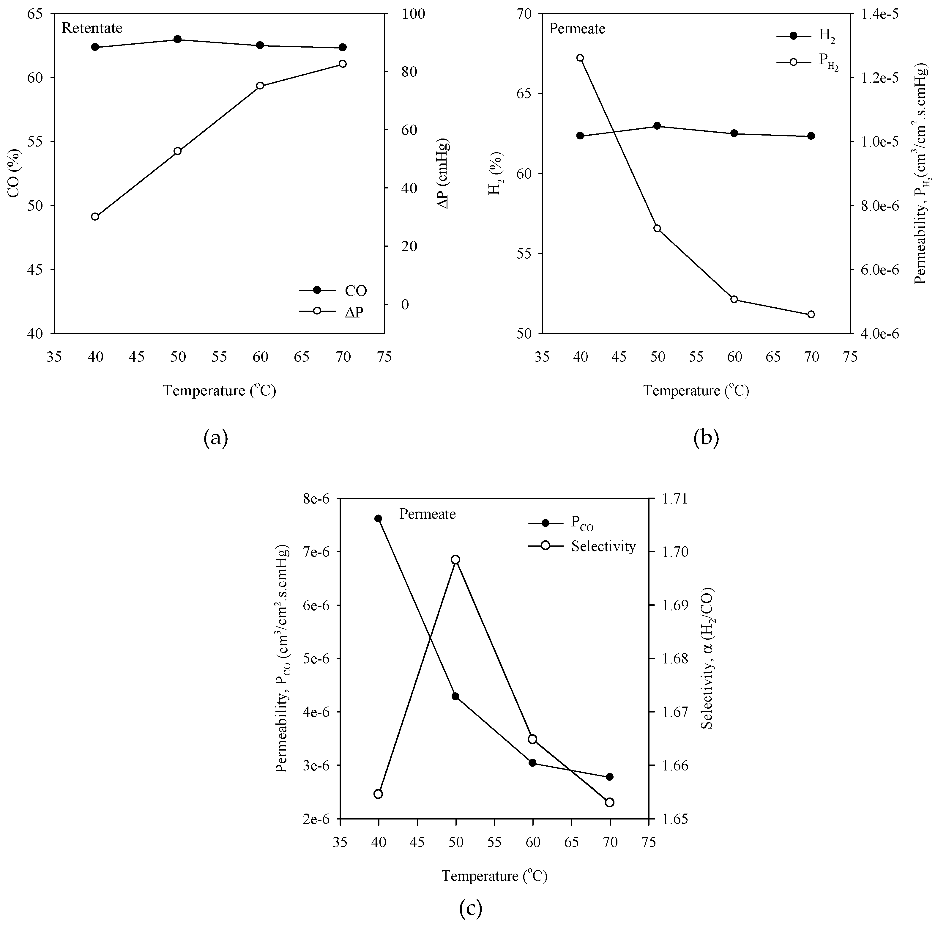
The effect of varying membrane module temperature on characteristics of CO/H2 separation was determined from the experiment and is demonstrated in Figure 6a–c. A stage cut of 50% for a gas flow rate of 400 cm3/min was considered with a gas inlet pressure of 6 bars. An increase in membrane temperature in this study increased the working pressure which however did not vary the CO and H2 purity. This is because with an increase in membrane module temperature solubility decreases while diffusivity increases thereby developing tradeoff relation for CO and H2 purity. The permeability of H2 and CO gradually decreases with increase in membrane module temperature due to the increase in kinetic diameter of CO and H2 which is increased on increasing the temperature. The kinetic diameter of H2 and CO was 2.9 and 3.6 Å, respectively [25]. The lower flow rate with increased driving force for a constant area, resulted in decreased permeability for CO and H2 as shown in Equations (1) and (2), a similar trend is reported in other studies [26,33,34]. Although the difference is not high, the selectivity of the membrane increased with an increase in membrane module temperature which again fell to its initial level on further increasing the membrane module temperature. Oana et al. [26] also obtained a gradual reduction trend in selectivity of H2 on increasing the membrane module temperature in a similar temperature range of this study. The increase in membrane module temperature demonstrated the negative effect on CO/H2 separation while using polyamide composite membrane. Contrarily, the study by Maryam et al. [35] obtained an increasing H2 permeability and selectivity on increasing the membrane module temperature while using hollow fiber polyimide membrane. The permeabilities of the gases at the temperature studied are similar to the temperature range studied by Markovic et al. [36]. Although for different gases like He, N2, Ar, CO2, and C3H8, reduction in permeabilities of various gases were obtained on increasing the membrane module temperature.
3.5. Estimation of Multistage Membrane Required for CO Purity
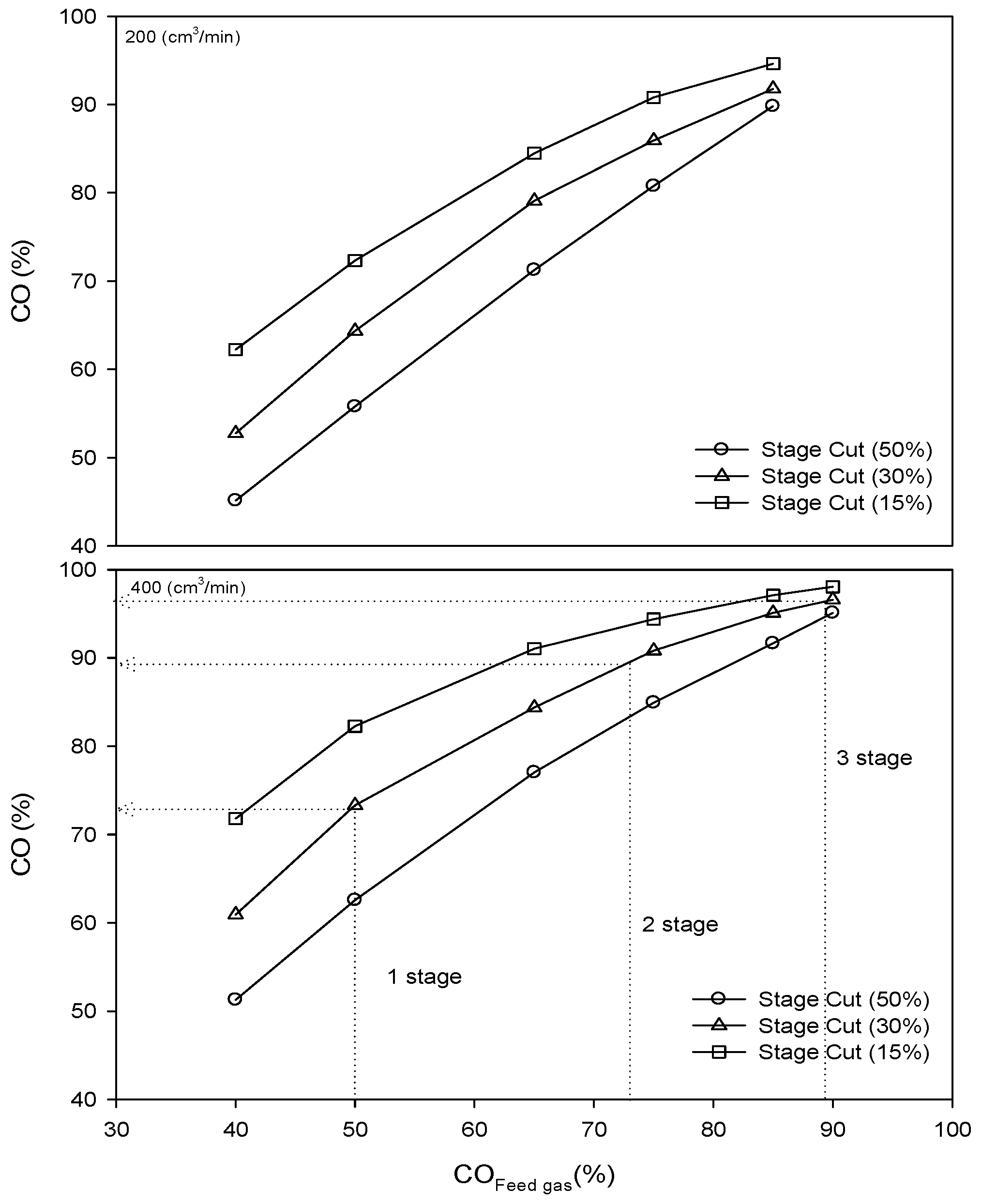
Figure 7 shows a graph demonstrating the CO purity for different stages in a multistage membrane system for the input gas flow rate of 200 and 400 cm3/min. It shows that CO purity can be obtained at every stage of the multi-stage membrane system for different stage cut and flow rates. The result obtained in this study reduces the effort to test for multistage gas separation, thus, reducing the preliminary cost. It can be inferred from the graph that at CO:H2 ratio of 50:50%, 97% pure CO can be obtained in the third stage of the multi-stage membrane system for 400 cm3/min. This, when passed through the 4th stage membrane, can generate CO purity percent of 99%. However, practically, along with the purity of CO, the recovery amount is very important for the economic feasibility of the membrane system. So, optimization of the CO purity percent and the recovery amount are indispensable.
It becomes evident that the use of single-stage membrane processes compromises the product purity and recovery as a trade-off that reduces separation performance compared to multistage membrane process [37]. In a multistage membrane system, there is a trade-off between permeate composition and permeate pressure, and, therefore, recompression costs incur. However, they are very useful in obtaining gas recovery above 95% [38]. Drioli et al. [39] suggested the multistage membrane system with highly permeable and less selective membranes in the first stage for enriching the stream of more permeable species and highly selective but less permeable membrane in the successive stages for achieving the high concentration of the desired species in retentate and permeate as a viable solution in the retentate and increase of CO as an impurity in the permeate. CO permeability initially decreased which increases on further increasing the flow rate. Initially, on increasing the gas flow rate, the separation efficiency of the membrane increased with an increase in working pressure. On further increasing the flow rate, CO was forced to pass through permeate thereby increasing the CO permeability. However, the increase in CO permeability reduces the CO/H2 separation efficiency. The selectivity of the membrane for H2 as it is the target product of permeate slightly increases with the increase in flow rate and decreases with a decrease in the stage cut.
4. Conclusions and Future Outlooks
CO and H2 purity, permeability, and its selectivity were studied as the process design characteristics of composite membrane based on various flow rates, stage cut, inlet pressures and membrane module temperatures. The study focused on the development of effective process design in implementing commercial polymeric membrane for syngas separation thereby reducing cost in CO/H2 separation which otherwise needs expensive inorganic membranes. The reduction in the stage cut enhances the CO purity while H2 purity is reduced while the permeability of CO and H2 decreases with an increase in the stage cut. However, the variation of inlet pressure did not demonstrate significant changes in CO/H2 separation. An increase in CO and H2 purity was observed while increasing the gas flow rates. A notable difference in CO/H2 separation characteristics was obtained for 200 and 400 cm3/min flow rate while the difference was minor for 400 and 600 cm3/min flow rate.
Increase in membrane module temperature had no effect on enhancing CO and H2 purity. However, the reduction in CO and H2 permeability was observed while increasing the membrane module temperature. This was due to the increase in kinetic diameter of CO and H2 with an increase in temperature. Multistage membrane process was found to be crucial in obtaining high purity CO. Ninety-seven percent pure CO was obtained for third stage arrangement of the composite membrane. The increase in the number of membranes will result in comparatively high purity of CO.
Although the results obtained show the possibility of its application in CO/H2 separation, further study is required to understand its performance in separating CO and H2 with consideration of recovery of individual components. Moreover, comparative analysis of the membrane should be done with the commercially available inorganic membranes to build a base for utilizing it in large scale gas separation applications. The increase in separation efficiency with lower stage cut will increase the recovery amount, and future research should be focused on enhancing recovery with reduced stage cuts which ultimately will increase its economic feasibility.
Author Contributions
J.P. was responsible for the overall experiment, data analysis and arrangement along with preparation of the manuscript; J.H.C. was responsible for the data analysis and editing of the manuscript. S.C.O. was the supervisor of the project and was mainly responsible for the data and manuscript confirmation. All the authors were equally responsible for finalizing the manuscript and submission.
Acknowledgments
This research was supported by the National Strategic Project-Carbon Upcycling of the National Research Foundation of Korea (NRF) funded by the Ministry of Science and ICT (MSIT), the Ministry of Environment (ME) and the Ministry of Trade, Industry and Energy (MOTIE) (No. 2017M3D8A2089593) and Waste to Energy Recycling Human Resource Development Project of Korea Ministry of Environment (ME).
Conflicts of Interest
The authors declare no conflicts of interest.
References
- Kwak, T.; Maken, S.; Lee, S.; Park, J.; Min, B.; Yoo, Y.D. Environmental Aspects of Gasification of Korean Municipal Solid Waste in a Pilot Plant. Fuel 2006, 85, 2012–2017. [Google Scholar] [CrossRef]
- Sakai, S.; Sawell, S.; Chandler, A.; Eighmy, T.; Kosson, D.; Vehlow, J.; Van der Sloot, H.; Hartlen, J.; Hjelmar, O. World Trends in Municipal Solid Waste Management. Waste Manag. 1996, 16. [Google Scholar] [CrossRef]
- Tchobanoglous, G.; Theisen, H.; Vigil, S.A.; Alaniz, V.M. Integrated Solid Waste Management: Engineering Principles and Management Issues; McGraw-Hill: New York, NY, USA, 1993. [Google Scholar]
- Murphy, J.D.; McKeogh, E. Technical, Economic and Environmental Analysis of Energy Production from Municipal Solid Waste. Renew. Energy 2004, 29, 1043–1057. [Google Scholar] [CrossRef]
- Alzate-Gaviria, L.M.; Sebastian, P.; Pérez-Hernández, A.; Eapen, D. Comparison of Two Anaerobic Systems for Hydrogen Production from the Organic Fraction of Municipal Solid Waste and Synthetic Wastewater. Int. J. Hydrogen Energy 2007, 32, 3141–3146. [Google Scholar] [CrossRef]
- Luo, S.; Xiao, B.; Hu, Z.; Liu, S.; Guan, Y.; Cai, L. Influence of Particle Size on Pyrolysis and Gasification Performance of Municipal Solid Waste in a Fixed Bed Reactor. Bioresour. Technol. 2010, 101, 6517–6520. [Google Scholar] [CrossRef] [PubMed]
- Desideri, U. Developments and Innovation in Carbon Dioxide (CO2) Capture and Storage Technology; Woodhead Publishing: Cambridge, UK, 2010. [Google Scholar]
- Nikolaidis, G.N.; Kikkinides, E.S.; Georgiadis, M.C. A Model-Based Approach for the Evaluation of New Zeolite 13X-Based Adsorbents for the Efficient Post-Combustion CO2 Capture using P/VSA Processes. Chem. Eng. Res. Des. 2018, 131, 362–374. [Google Scholar] [CrossRef]
- Cavenati, S.; Grande, C.A.; Rodrigues, A.E. Separation of CH4/CO2/N2 Mixtures by Layered Pressure Swing Adsorption for Upgrade of Natural Gas. Chem. Eng. Sci. 2006, 61, 3893–3906. [Google Scholar] [CrossRef]
- DiMartino, S.; Glazer, J.; Houston, C.; Schott, M. Hydrogen/Carbon Monoxide Separation with Cellulose Acetate Membranes. Gas Sep. Purif. 1988, 2, 120–125. [Google Scholar] [CrossRef]
- Khanipour, M.; Mirvakili, A.; Bakhtyari, A.; Farniaei, M.; Rahimpour, M.R. Enhancement of Synthesis Gas and Methanol Production by Flare Gas Recovery Utilizing a Membrane Based Separation Process. Fuel Process. Technol. 2017, 166, 186–201. [Google Scholar] [CrossRef]
- Dutta, N.; Patil, G. Developments in CO Separation. Gas Sep. Purif. 1995, 4, 277–283. [Google Scholar] [CrossRef]
- Hsieh, H. Inorganic Membranes for Separation and Reaction; Elsevier: Amsterdam, The Netherlands, 1996. [Google Scholar]
- Koros, W.J.; Mahajan, R. Pushing the Limits on Possibilities for Large Scale Gas Separation: Which Strategies? J. Membr. Sci. 2000, 175, 181–196. [Google Scholar] [CrossRef]
- Ho, W.; Sirkar, K. Membrane Handbook; Springer Science & Business Media: Berlin/Heidelberg, Germany, 2012. [Google Scholar]
- Bhadra, S.; Farooq, S. Separation of Methane–nitrogen Mixture by Pressure Swing Adsorption for Natural Gas Upgrading. Ind. Eng. Chem. Res. 2011, 50, 14030–14045. [Google Scholar] [CrossRef]
- Corbett, L. Industrial Engineering Chemistry Process Design and Development; American Chemical Society: Washington, DC, USA, 1975; Volume 13, p. 181. [Google Scholar]
- Lu, G.Q.; Da Costa, J.D.; Duke, M.; Giessler, S.; Socolow, R.; Williams, R.H.; Kreutz, T. Inorganic membranes for hydrogen production and purification: A critical review. J. Colloid Interface Sci. 2007, 314, 589–603. [Google Scholar] [CrossRef] [PubMed]
- Basile, A.; Gallucci, F.; Tosti, S. Synthesis, characterization and applications of palladium membranes. Membr. Sci. Technol. 2008, 13, 255–323. [Google Scholar]
- Sanchez, J.M.; Barreiro, MM.; Marono, M. Hydrogen enrichment and separation from synthesis gas by the use of a membrane reactor. Biomass Bioenergy 2011, 35, S132–S144. [Google Scholar] [CrossRef]
- Shimekit, B.; Mukhtar, H. Natural Gas Purification Technologies-Major Advances for CO2 Separation and Future Directions; INTECH Open Access Publisher: London, UK, 2012; pp. 235–270. [Google Scholar]
- Robeson, L.M. The upper bound revisited. J. Membr. Sci. 2008, 320, 390–400. [Google Scholar] [CrossRef]
- Noble, R.D. Perspectives on mixed matrix membranes. J. Membr. Sci. 2011, 15, 393–397. [Google Scholar] [CrossRef]
- Scholes, C.A. Membrane gas separation applications in natural gas processing. Fuel 2012, 96, 15–28. [Google Scholar] [CrossRef]
- Meulenberg, W.A.; Hansch, R.; Buchkremer, H.P.; Stöver, D. Device for Gas Separation and Method for Producing such a System. U.S. Patent 8,016,924, 13 September 2011. [Google Scholar]
- David, O.C.; Gorri, D.; Urtiaga, A.; Ortiz, I. Mixed Gas Separation Study for the Hydrogen Recovery from H2/CO/N2/CO2 Post Combustion Mixtures using a Matrimid Membrane. J. Membr. Sci. 2011, 378, 359–368. [Google Scholar] [CrossRef]
- Koros, W.J.; Fleming, G. Membrane-Based Gas Separation. J. Membr. Sci. 1993, 83, 1–80. [Google Scholar] [CrossRef]
- Javaid, A. Membranes for Solubility-Based Gas Separation Applications. Chem. Eng. J. 2005, 112, 219–226. [Google Scholar] [CrossRef]
- Hines, A.L.; Maddox, R.N. Mass Transfer: Fundamentals and Applications; Prentice-Hall: Englewood Cliffs, NJ, USA, 1985. [Google Scholar]
- Lin, H.; Freeman, B.D. Gas Solubility, Diffusivity and Permeability in Poly (Ethylene Oxide). J. Membr. Sci. 2004, 239, 105–117. [Google Scholar] [CrossRef]
- Reid, R.C.; Prausnitz, J.M.; Poling, B.E. The Properties of Gases and Liquids; Mcgraw-Hill: New York, NY, USA, 1987. [Google Scholar]
- Robeson, L.M.; Smith, Z.P.; Freeman, B.D.; Paul, D.R. Contributions of Diffusion and Solubility Selectivity to the Upper Bound Analysis for Glassy Gas Separation Membranes. J. Membr. Sci. 2014, 453, 71–83. [Google Scholar] [CrossRef]
- El-Azzami, L.A.; Grulke, E.A. Dual Mode Model for Mixed Gas Permeation of CO2, H2, and N2 through a Dry Chitosan Membrane. J. Polym. Sci. Part B Polym. Phys. 2007, 45, 2620–2631. [Google Scholar] [CrossRef]
- Tanaka, K.; Kita, H.; Okamoto, K.; Nakamura, A.; Kusuki, Y. Gas Permeability and Permselectivity in Polyimides Based on 3,3′,4,4′-Biphenyltetracarboxylic Dianhydride. J. Membr. Sci. 1989, 47, 203–215. [Google Scholar] [CrossRef]
- Peer, M.; Mehdi Kamali, S.; Mahdeyarfar, M.; Mohammadi, T. Separation of Hydrogen from Carbon Monoxide using a Hollow Fiber Polyimide Membrane: Experimental and Simulation. Chem. Eng. Technol. 2007, 30, 1418–1425. [Google Scholar] [CrossRef]
- Marković, A.; Stoltenberg, D.; Enke, D.; Schlünder, E.; Seidel-Morgenstern, A. Gas Permeation through Porous Glass Membranes: Part I. Mesoporous Glasses—Effect of Pore Diameter and Surface Properties. J. Membr. Sci. 2009, 336, 17–31. [Google Scholar]
- Zarca, G.; Urtiaga, A.; Biegler, L.T.; Ortiz, I. An Optimization Model for Assessment of Membrane-Based Post-Combustion Gas Upcycling into Hydrogen or Syngas. J. Membr. Sci. 2018, 563, 83–92. [Google Scholar] [CrossRef]
- Bernardo, P.; Drioli, E.; Golemme, G. Membrane Gas Separation: A Review/State of the Art. Ind. Eng. Chem. Res. 2009, 48, 4638–4663. [Google Scholar] [CrossRef]
- Drioli, M.S.B.; Barbieri, G. CO2-CH4 Membrane Separation. Available online: http://dx.medra.org/10.17374/CI.2015.97.5.14 (accessed on 15 September 2017).
Figure 1.
Schematic diagram of the membrane system.

Figure 2.
Schematic Representation of Braid-reinforced hollow fiber pervaporation membrane.

Figure 3.
Characteristics of CO/H2 separation with increasing flow rates at 6 bars inlet pressure for various stage cut (a) CO% & ΔP, (b) H2% & PH2, and (c) PCO & α(H2/CO).
Figure 3.
Characteristics of CO/H2 separation with increasing flow rates at 6 bars inlet pressure for various stage cut (a) CO% & ΔP, (b) H2% & PH2, and (c) PCO & α(H2/CO).

Figure 4.
Characteristics of CO/H2 separation with increasing flow rates at 70% stage cut for various inlet pressures (a) CO% & ΔP, (b) H2% & PH2, and (c) PCO & α(H2/CO).
Figure 4.
Characteristics of CO/H2 separation with increasing flow rates at 70% stage cut for various inlet pressures (a) CO% & ΔP, (b) H2% & PH2, and (c) PCO & α(H2/CO).

Figure 5.
Characteristics of CO/H2 separation with increasing stage cut at 6 bars inlet pressure for various inlet flow rates (a) CO% & ΔP, (b) H2% & PH2, and (c) PCO & α(H2/CO).
Figure 5.
Characteristics of CO/H2 separation with increasing stage cut at 6 bars inlet pressure for various inlet flow rates (a) CO% & ΔP, (b) H2% & PH2, and (c) PCO & α(H2/CO).

Figure 6.
Characteristics of CO/H2 separation with increasing membrane cut at 6 bars inlet pressure for 400 cm3/min flow rate and a stage cut of 50% (a) CO% & ΔP, (b) H2% & PH2, and (c) PCO & α(H2/CO).
Figure 6.
Characteristics of CO/H2 separation with increasing membrane cut at 6 bars inlet pressure for 400 cm3/min flow rate and a stage cut of 50% (a) CO% & ΔP, (b) H2% & PH2, and (c) PCO & α(H2/CO).

Figure 7.
Figure showing the cumulative data of CO separation characteristics at various CO: H2 concentrations for input pressure of 6 bars to estimate the multistage number required.
Figure 7.
Figure showing the cumulative data of CO separation characteristics at various CO: H2 concentrations for input pressure of 6 bars to estimate the multistage number required.

© 2019 by the authors. Licensee MDPI, Basel, Switzerland. This article is an open access article distributed under the terms and conditions of the Creative Commons Attribution (CC BY) license (http://creativecommons.org/licenses/by/4.0/).
Share and Cite
MDPI and ACS Style
Poudel, J.; Choi, J.H.; Oh, S.C. Process Design Characteristics of Syngas (CO/H2) Separation Using Composite Membrane. Sustainability 2019, 11, 703. https://0-doi-org.brum.beds.ac.uk/10.3390/su11030703
AMA Style
Poudel J, Choi JH, Oh SC. Process Design Characteristics of Syngas (CO/H2) Separation Using Composite Membrane. Sustainability. 2019; 11(3):703. https://0-doi-org.brum.beds.ac.uk/10.3390/su11030703
Chicago/Turabian StylePoudel, Jeeban, Ja Hyung Choi, and Sea Cheon Oh. 2019. "Process Design Characteristics of Syngas (CO/H2) Separation Using Composite Membrane" Sustainability 11, no. 3: 703. https://0-doi-org.brum.beds.ac.uk/10.3390/su11030703
Note that from the first issue of 2016, this journal uses article numbers instead of page numbers. See further details here.