Article

Strength Variation of Rocks Surrounding Road Tunnel Entrance/Exit in High–Altitude Mountain Areas under Freeze–Thaw Cycles

1
School of Geological and Mining Engineering, Xinjiang University, Urumqi 830017, China
2
Geological Exploration in the Chinese Building Materials Center Team in Gansu Province, Tianshui 741000, China
3
State Key Laboratory for Geomechanics and Deep Underground Engineering, Xinjiang University, Urumqi 830017, China
*
Author to whom correspondence should be addressed.
Sustainability 2022, 14(15), 9305; https://0-doi-org.brum.beds.ac.uk/10.3390/su14159305
Submission received: 29 May 2022 / Revised: 25 July 2022 / Accepted: 27 July 2022 / Published: 29 July 2022

Abstract

:
The Duku Highway in the study area is located in the high-altitude mountainous region of Xinjiang, China, and it is affected by various environmental factors during construction, among which the influence of freeze–thaw cycles cannot be ignored. In order to study the effect of freeze–thaw cycles on the strength of tuff surrounding rock at high-altitude mountainous areas, uniaxial compressive strength and shear wave velocity tests with different numbers of freeze–thaw cycles were conducted on dry and saturated rock samples from the tunnel entrance of the Duku Highway. The test results showed that the tuff specimens condensed a thin layer of ice on the surface with raised freezing points during the freezing stage, but the thickness of the thin ice and the density of the freezing points did not change with the increase of the number of freeze–thaw cycles. Analysis of the test data showed that the wave velocity, uniaxial compressive strength, breaking strain, modulus of elasticity, and Poisson’s ratio of the rock decreased as the number of freeze–thaw cycles increased. We believe that the freeze–thaw cycles caused the deterioration of the rock strength. The reason for this phenomenon is that we believe that the freeze–thaw cycling action changed the rock internally and affected its density, which, in turn, caused the attenuation of strength, etc. However, there is a limit to the effect of freeze–thaw cycling on the strength of the surrounding rock. After exceeding the limit of the effect of freeze–thaw cycling, the strength parameters of the surrounding rock will no longer change with the increase of the number of freeze–thaw cycles. The results of this study can provide a theoretical basis for the prevention and control of the stability of tuff surroundings at high-altitude mountain tunnel openings.

1. Introduction

Located in Xinjiang Province, China, the Duku Road connects the north and south of the Tianshan Mountains. The road is greatly affected by landform, climate, and geological disasters, causing severe security risks to people and vehicles on the road. In addition, the annual operation time is only five months (from June to October), which has a significant impact on the economic development of the north and south of the Tianshan Mountains. Therefore, building an all-weather bridge-tunnel highway across the north and south of the Tianshan Mountains is particularly important.
This site in the Tianshan Mountain area is at a high altitude. Some areas are up to 3700 m above sea level, belonging to the cold climate plateau area. According to the local meteorological data, the lowest ambient temperature can reach −40 °C, while the temperature is relatively high in summer, The highest temperature can reach 40 °C. Thus, the strength and stability of rocks surrounding the tunnel entrance/exit are affected by temperature changes. Rock mass engineering failure caused by freeze–thaw is a familiar construction problem encountered in high-altitude cold regions. For example, tunnel lining cracking caused by the frost heave of the surrounding rock is one of the primary forms of tunnel failure in cold areas [1,2]. This paper investigated the effect of freeze–thaw cycles on the strength changes in rocks at the tunnel entrance/exit.

1.1. Studies of High-Altitude Mountain Areas

For the study of high-altitude mountainous areas, some scholars [3,4,5,6] studied the evaluation of geological hazards such as mudslides on roads with typical alpine and high-altitude mountainous areas, as well as the hazards and prevention of roads. Some scholars [7,8,9] mainly studied the research on roadbed design and safety evaluation as well as safeguard measures of highways. It can be seen that, at present, for high-altitude mountainous areas, the main research is on the characteristics of highway geological hazards and safety evaluation, etc., and the research on the strength change of high-altitude highway tunnel entrances surrounding rocks under freeze–thaw cycle conditions studied in this paper is slightly insufficient.

1.2. Studies of Freezing–Thawing Cycles and Rocks

Yavuz et al. [10] found that the rock samples’ P-wave velocity decreased after 20 freeze–thaw cycles. Momeni et al. [11] investigated the impacts of freeze–thaw cycles on rocks’ physical and mechanical properties. Ghobadi et al. [12] conducted freeze–thaw cycle tests on the sandstone in Iran, analyzing its physical and mechanical loss. Yambae et al. [13] reported that the uniaxial compressive strength of rocks dropped as the number of freezing–thawing cycles increased. Based on experiments, Fahey et al. [14] found that weathering on shale was 3–4 times stronger than freeze–thaw cycles. Matsuoka et al. [15] demonstrated that freeze–thaw failure occurs in rock when exposed to the open aquifer system. Liu et al. [16] reported impacts of freeze–thaw cycles on rock weathering and variations of physical and mechanical parameters of rocks after freeze–thaw cycles. Wan et al. [17] found that the surrounding rocks’ physical and mechanical properties decreased as the freeze–thaw process continued, changing laws at different stages. Xu et al. [18,19] examined the failure characteristics of rock under various conditions such as other forces, cyclic temperatures, and water contents.
Rong et al. [20] conducted laboratory physical and mechanical performance tests and found the tensile, compressive, and shear performance of intact rock samples and the shear characteristics of its structural discontinuity plane. Zhang et al. [21] studied the impacts of rock characters and freeze–thaw cycles on the damage mechanics of rock. Liu et al. [22] found that after freeze–thaw cycling, the mass, longitudinal wave velocity, and coefficient of heat conductivity of the rock sample increased before decreasing. In contrast, the uniaxial compressive strength decreased monotonically, and the elastic modulus and peak strain increased as the number of freezing–thawing cycles increased. Inada et al. [23] showed that both rock’s tensile and compressive strength increased as the temperature increased. Tang et al. [24] demonstrated that as the number of freeze–thaw cycles grew, the rock compressive strength, cohesion, internal angle of friction, and elastic modulus would reduce gradually, whereas the Poisson’s ratio would increase. Hou et al. [25] reported that the rock compressive strength, tensile strength, and elastic modulus declined exponentially as the number of freeze–thaw cycles grew. Shen et al. [26] found that rock wave velocity reflects the degradation during freeze–thaw cycles, and the uniaxial compressive strength and elastic modulus declined exponentially. At the same time, the dynamic Poisson’s ratio increased exponentially as the number of freeze–thaw cycles grew. Wu et al. [27] demonstrated that elastic and secant moduli of rock-like materials decreased as the number of freeze–thaw cycles increased. Jiang et al. [28] reported that freeze–thaw cycles caused minor freeze–thaw damage to rock samples. Liu et al. [29] found that the frost-heave force of the surrounding rock would increase and be constant as the number of freeze–thaw cycles increased based on the theoretical calculation of the frost-heave force in the tunnel of the surrounding rock under freeze–thaw cycles, developing, later on, the rock damage model [30,31,32,33]. Al-Omari et al. [34] studied the internal damage of the porous structures of limestone and the surface spalling under thermal stress, condense, and freeze–thaw cycles. Wang M et al. [35] have studied the fracture behavior of mixed-model I/II cracks under dynamic loads. Tensile crack softening failure criterion is used to study impact-induced crack initiation and propagation in rocks [36]. The crack propagation toughness of tight sandstone under different loading rates was investigated [37]. The microstructure changes of specimens induced by cyclic freeze–thaw were measured using nuclear magnetic, the results show that the cyclic freeze–thaw plays an important part in rock dynamic fracture behavior [38].
In summary, current studies on this issue at home and abroad mainly explore the changes of compressive and shear strengths through freeze–thaw cycling of different types of rock and soil bodies. However, the analysis and research on the rock strength in high-altitude areas and tunnel entrances surrounded by freeze–thaw cycling deterioration remained weak. There is no research on rock quality changes under freeze–thaw cycling in the cold region of Duku Road.
This paper studied the variation rules of rock strength parameters in this area under freeze–thaw cycles based on relevant laboratory tests and theoretical analysis. The impacts of freeze–thaw cycles on strength parameters of rocks at the tunnel entrance/exit were analyzed and summarized.

2. Materials and Methods

2.1. Selection of Study Area

This study aimed to clarify variations of strength parameters of rocks surrounding the road tunnel entrance/exit in high-altitude mountainous areas under freeze–thaw cycles. Hence, the study area should meet the requirement of the test, i.e., having the capacity of simulating the freeze–thaw cycling. Furthermore, the proposed Duku Road (Figure 1) is in a high-altitude mountainous area, where the temperature difference between summer and winter was as high as 80 °C. Hence, this place naturally satisfied the requirement of the freeze–thaw test.

2.2. Sample Selection and Preparation

Test samples were from the rock surrounding the tunnel entrance/exit in the proposed Duku Road of G217. The rock sample taken is tuff. Figure 2 illustrates the sampling process used to obtain the standard-sized test sample (50 mm in diameter and 100 mm in height) through field coring and laboratory processing.

2.3. Specimen Characteristics

After sampling the site drilling, representative blocks of the proposed tunnel site were selected for lithological analysis, and it is known that the surrounding rock at the proposed tunnel entrance is mainly tuff stratigraphy. The lithology of the stratum is Yingan crystal glass chip tuff. This layer of tuff is tuff structure, block structure, debris composition is mainly glass chips and crystal chips, medium sorting, of which crystal chips account for about 60%, rock chips account for about 7%, glass chips about 13%, de-glassing is obvious, and sericitization and mudification of feldspar crystal chips occur. In this paper, we mainly focus on the above tuffs.

2.4. Experimental Design

We tested the uniaxial compressive strength and shear wave velocity of rocks after different numbers of freeze–thaw cycles in the laboratory and discussed the influence of freeze–thaw cycling on rock strength by analyzing experimental data.
Rock samples were divided into two groups in this experiment to simulate precipitation and drought environments in mountain areas. We obtained one group of samples when there was no natural precipitation. However, due to the substantial amount of local evaporation, annual evaporation reached 3008.9 mm, so these samples had low water content as dry samples. Therefore, we made the other samples by placing the dry samples in clean water for 24 h to simulate the tunnel entrance/exit surrounding rock situation after heavy natural precipitation. Therefore, this sample group was immersion-saturated, because the water in the natural tunnel entrance/exit surrounding rock only penetrates the crack during precipitation and no longer absorbs water after reaching a certain degree but was not fully saturated. Thus, this sample group simulated the surrounding rock after high natural rainfall.
According to the local meteorological data, the annual temperature difference in this area was excellent. The extreme maximum temperature in the summer project area can reach 40 °C, and the low winter temperature can reach −40 °C. In the laboratory experiment, the maximum temperature of freeze–thaw cycles was 40 °C, and the lowest temperature was −40 °C. One freeze–thaw cycle lasted for eight hours, i.e., four hours of freezing and four hours of thawing.
The freeze–thaw cycles were 0, 5, 10, 15, 20, 25, and 30. Freeze–thaw cycles were controlled using the programmable humidity chamber (constant temperature and humidity).

2.5. Procedures

2.5.1. Sample Grouping

According to the experimental design, the samples comprised two large groups, the dry sample groups and the saturated sample groups, and the number of samples in each group met the standard requirements and parallel experiments to ensure the data reliability and accuracy of the study. Therefore, as shown in Table 1, the dry samples were labeled G1~G7 groups and the immersion-saturated samples were S1~S7 groups. According to the relevant specifications, the number of samples in groups G1~G7 as well as S1~S7 was 3 for each group, totaling 14 groups and 42 specimens.

2.5.2. Freeze–Thaw Test

According to the experimental program, two groups of rock samples were put into the humidity chamber (with constant temperature and humidity), with preset freezing–thawing test temperature and time according to the test scheme. Then, according to the program, every five freezing–thawing cycles, the corresponding sample from the humidity chamber (with constant temperature and humidity) was used immediately for the shear wave speed and uniaxial compressive tests.
Figure 3 shows the freeze–thaw test temperature pattern. In addition, it shows, during two freeze–thaw cycles in the test box, the process of practical temperature in experimental temperature and experimental humidity chamber change process.

2.5.3. Shear Wave Velocity Test

A shear wave velocity test used the acoustic detector on the freeze–thaw test samples. As shown in Figure 4, Vaseline was first evenly smeared on the upper and lower surfaces of the sample, and the transmitter and receiver of the signal acquisition were attached to the upper and lower surfaces of the sample to collect shear wave speed samples.

2.5.4. Uniaxial Compressive Strength Test

According to the test design, uniaxial compressive strength tested rock samples with cycles of 0, 5, 10, 15, 20, 25, and 30. Thus, we determined the influence of freeze–thaw cycling on rock strength parameters and explored its variation rule.
After exposure to the freeze–thaw cycles, we removed the samples. First, two groups of resistance strain gauges were pasted symmetrically on the outer wall of the sample in the transverse and axial, respectively (see Figure 5), to observe the strain change of the sample during uniaxial compression. Then, we placed the sample on the compression testing machine and wired the resistance strain gauges to the resistance strain meter. Finally, the test was started after debugging (Figure 6).

3. Results and Analysis

3.1. Analysis of Apparent Phenomena of Freeze–Thaw Testing

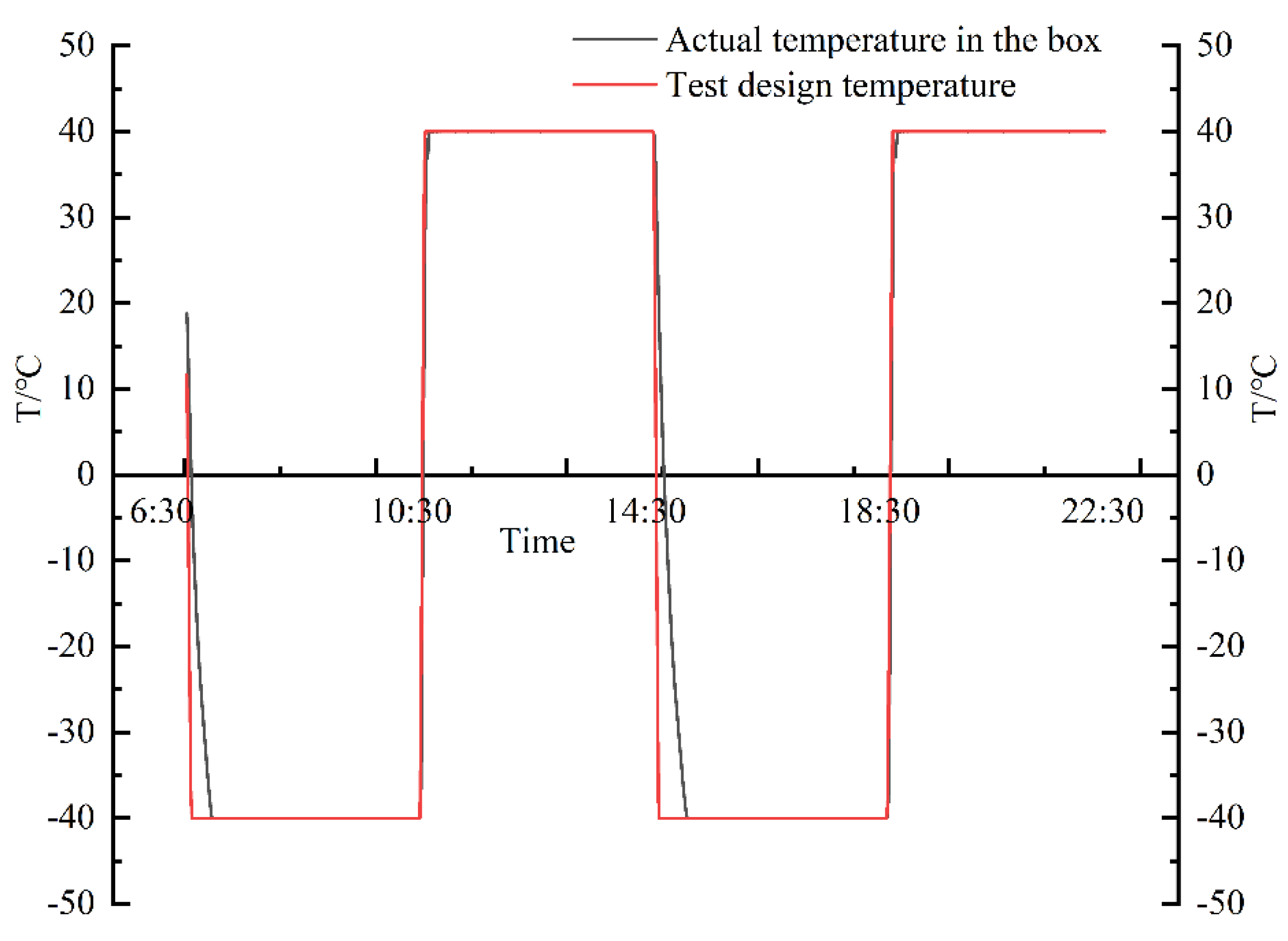
Figure 3 shows trends of freezing–thawing test temperatures. In freeze–thaw cycles, sample practical temperatures rapidly reduced from room temperature to the designed −40 °C within 28 min. For example, it took only 36 min for the sample experimental temperature to decrease from 40 °C to −40 °C and only 14 min to heat from −40 °C to 40 °C. Therefore, when the temperature is between −40 °C and 40 °C, the rising rate of rock temperature is 2.57 times the falling rate.
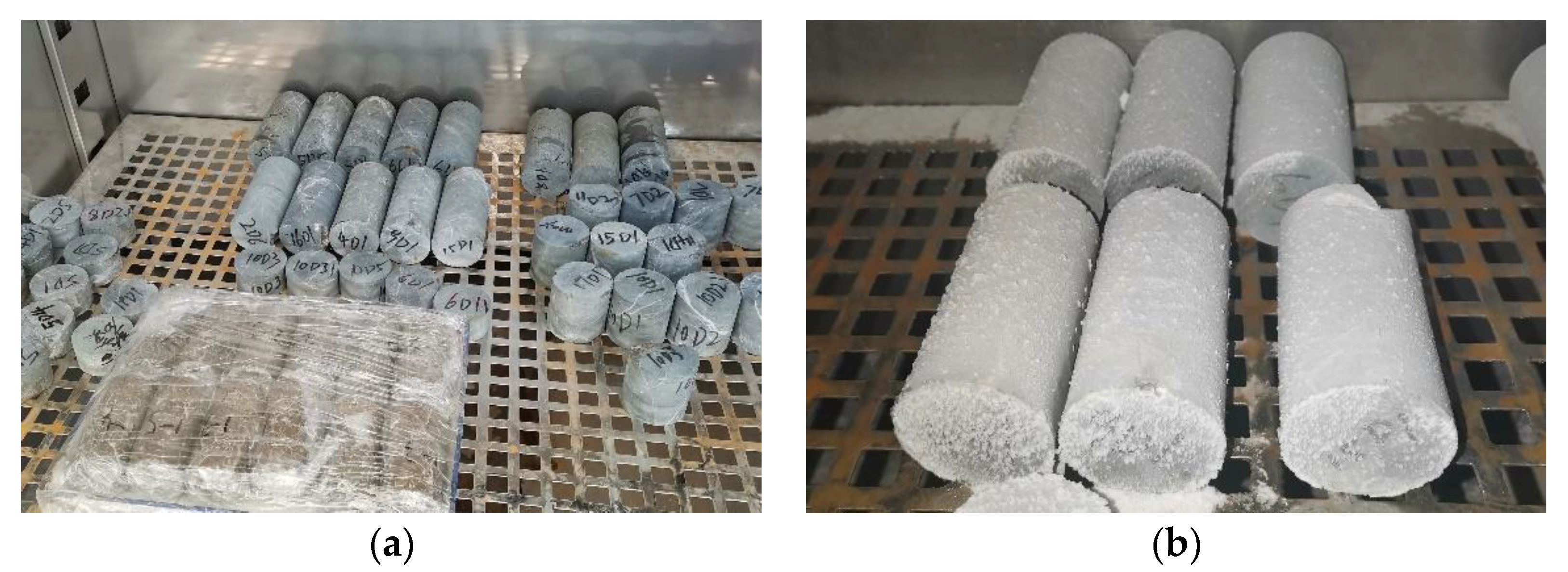
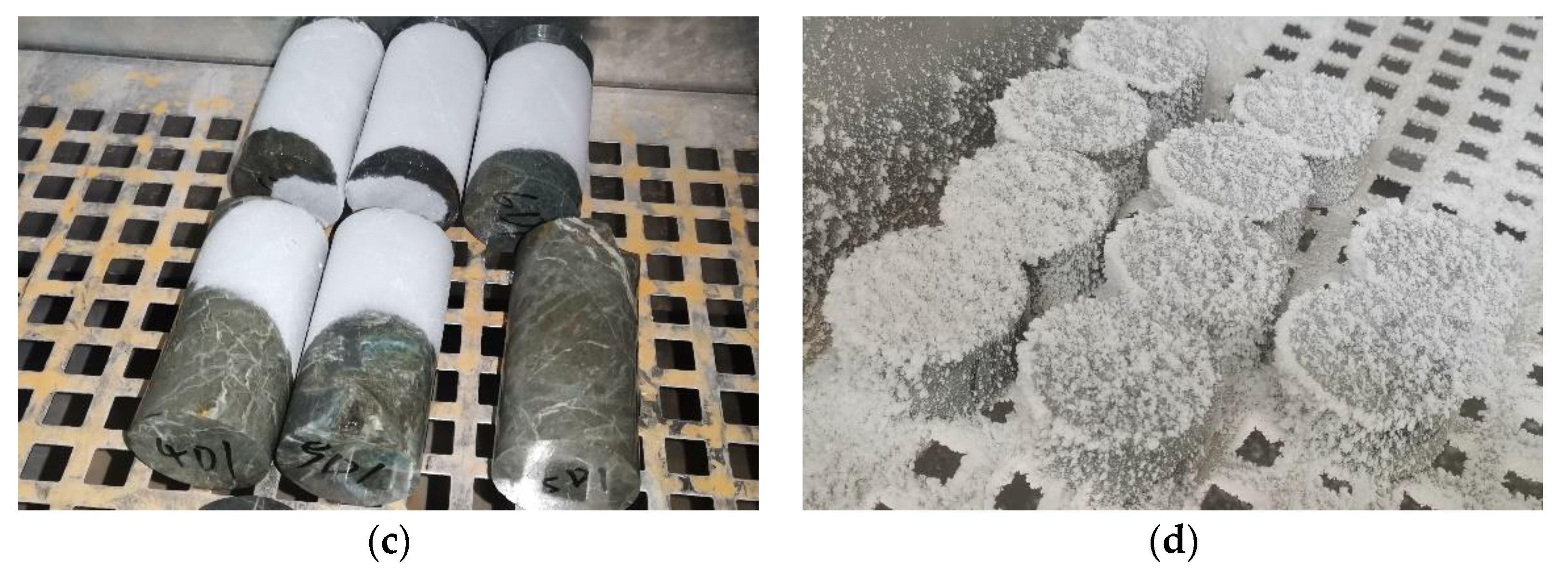
Figure 7 shows sample appearance at different freeze–thaw cycling stages. Figure 7a shows the original samples before the freeze–thaw test, without moisture and ice on the surface. Figure 7b shows the appearance of a dry sample after being deep-frozen. It has a thin layer of ice distributed with granular protrusion freezing points, and the sample was visible from the upper and bottom surfaces. Figure 7c shows the sample situation after freezing and beginning high-temperature ablation for a while. The frozen thin ice on its surface gradually melts, and the ablation process starts from the upper surface and gradually melts downward, in which the surface granular protrusion freezing point melts first. Figure 7d is the deep-frozen immersion-saturated sample. Its surface ice was more significant than in the dry sample, the granular protrusion freezing point was denser, and the sample was not visible from the upper or bottom surface.
After several freeze–thaw tests, the apparent analysis revealed that the sample showed no evident changes in the surface ice thickness and freezing point density after several cycles. The surface ice thickness of the dry sample was slightly smaller than that of the immersion-saturated sample. As a result, the granular protrusion freezing points were more sparsely distributed than the immersion-saturated sample.

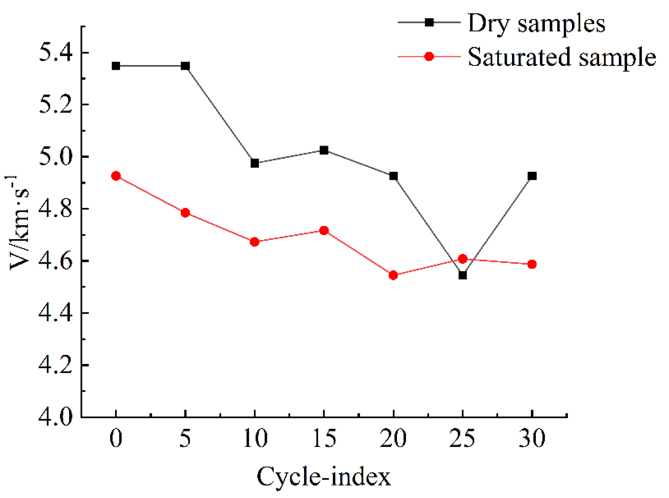
3.2. Shear Wave Velocity Test

Table 2 illustrates the impacts of freezing–thawing cycling on shear wave speed and amplitude of rocks. As shown in Table 2 and Figure 8, shear wave speeds of dry and immersion-saturated samples decreased as the number of freezing–thawing cycles increased. After the first 30 freezing–thawing cycles, the shear wave speeds of dry and immersion-saturated samples decreased by 0.8 and 0.34 km/s. The wave speed of the dry sample was significantly higher than that of the immersion-saturated sample.
As the number of freeze–thaw cycles increased, the difference in shear wave velocity between the two types of samples reduced, suggesting that, after a certain number of cycles, the difference between a dry sample and an immersion-saturated sample became less, and the wave velocity tended to stabilize, and no significant fluctuation was generated.
As shown in Table 2 and 
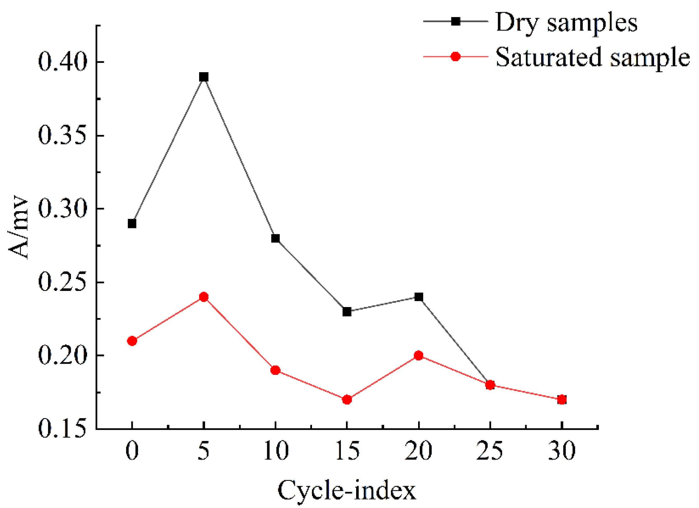
Figure 9, both amplitudes increased before decreasing with the increasing number of freeze–thaw cycles. In addition, the dry sample had a more apparent decreasing trend.
During the first five cycles, the amplitudes of both dry and immersion-saturated samples increased with the number of freeze–thaw cycles. However, the rate of amplitude increase of the dry sample was significantly higher than that of the immersion-saturated sample. Both amplitudes decreased after the 5th freeze–thaw cycle, and both amplitudes were stable after the 25th cycle. We predicted that after freeze–thaw cycles of a limited number of cycles, amplitudes of both samples decreased, stabilizing after a limited number of cycles, with no significant fluctuation with the increase of the cycle number.
According to the physical properties of waves, the freeze–thaw cycle test changes the nature of the propagating medium to a certain extent, which, in turn, leads to a change in the wave velocity.
V = h T
In Equation (1), V is the speed of sound in km/s; T is the sound time in μs; h is the height of the specimen in m.
c = λ f
In Equation (2), c is the wave speed, λ is the wavelength, and f is the frequency of the wave.
According to Equations (1) and (2), the propagation medium changes the wavelength, which, in turn, leads to a decrease in wave speed. Since the biggest difference between different propagation media is density, the analysis concluded that the freeze–thaw cycling action changed the density of the specimens, and there was a slight difference in the density of the specimens after different numbers of freeze–thaw cycles.
Zhu G. et al. [39] analyzed that the density is proportional to the wave velocity, and according to the wave velocity test results, as the number of freeze–thaw cycles increases, the specimen wave velocity decreases, that is, the density decreases.
According to the test results of water-saturated specimens and dry specimens, there is a difference, the analysis that the reason for this change is that the specimen after immersion in water changes the density of the specimen, etc., water fills the tiny voids inside the specimen, and the difference in the propagation medium causes the difference in wave speed and amplitude of the two specimens. The trend of wave velocity and amplitude after specimen immersion is relatively flat, and the analysis suggests that the difference between each specimen is reduced after water enters the tiny voids inside the specimen, which changes the wave propagation medium, so the trend is relatively flat, and the effect of freeze–thaw cycles on some properties of the rock, so that the wave velocity gradually decreases with the increase of the number of freeze–thaw cycles.

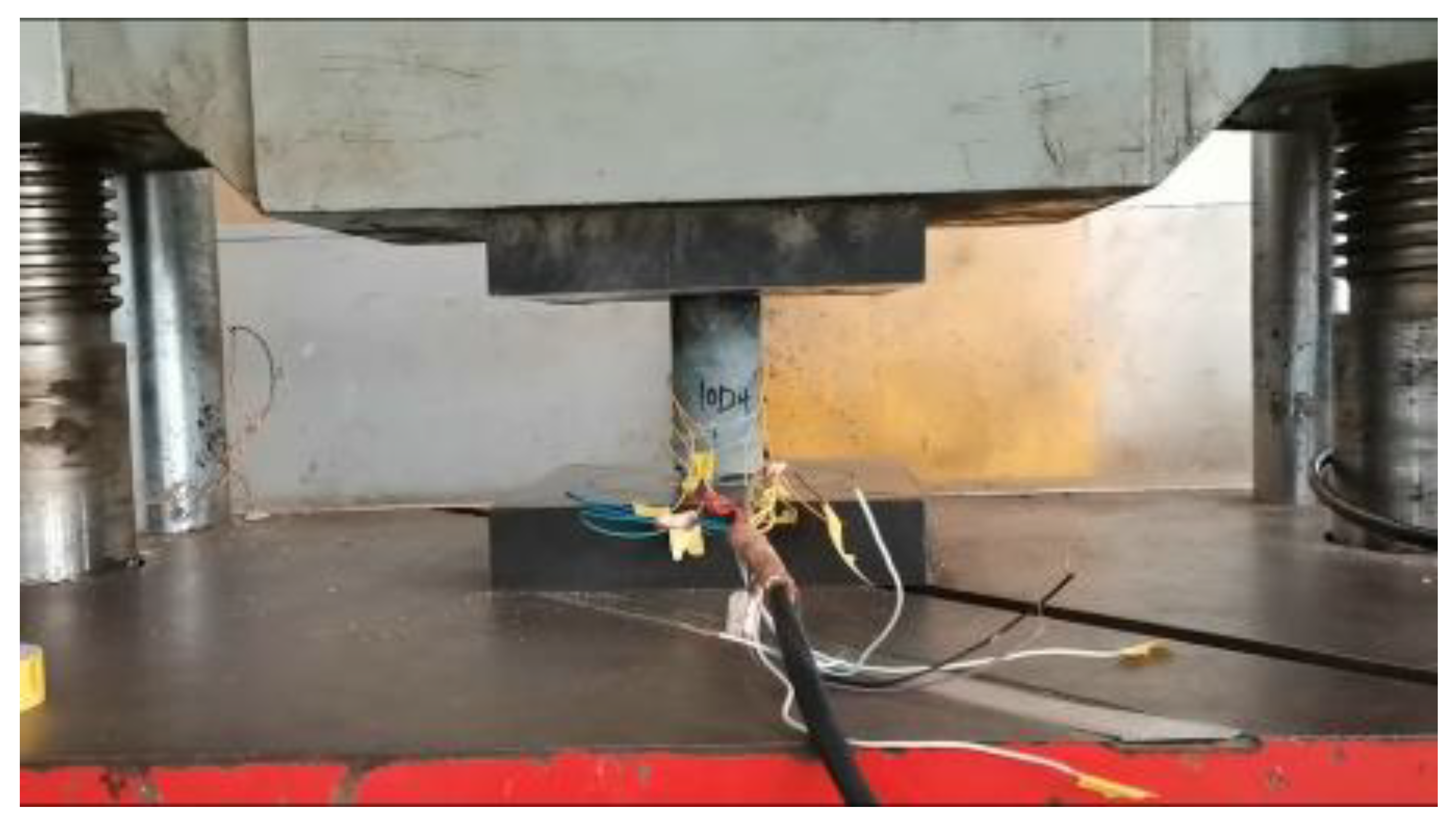
3.3. Uniaxial Compressive Strength Test

Table 3 illustrates the impacts of freeze–thaw cycling on the strength parameters of rocks.
According to Table 3 and 
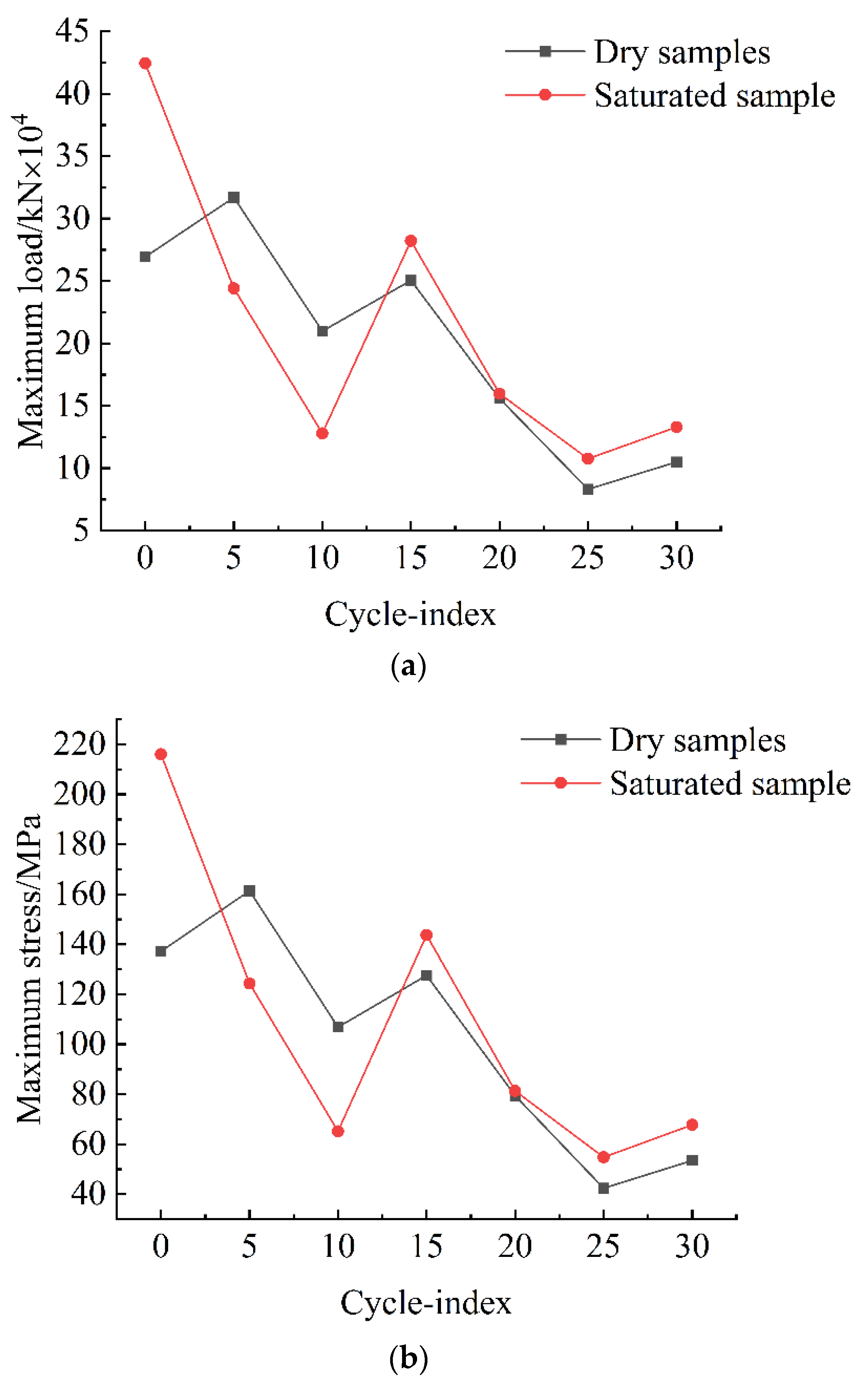
Figure 10, the uniaxial compressive strengths of samples decreased as the number of freeze–thaw cycles increased. Before the 13th freeze–thaw cycle, the uniaxial compressive strength of dry samples was significantly higher than that of immersion-saturated samples. However, the strengths of both samples decreased with the increasing number of freeze–thaw cycles. After the 13th freeze–thaw cycle, the strength of immersion-saturated samples was slightly larger than that of dry rock samples. However, with the increase in the number of freezing–thawing cycles, the uniaxial compressive strengths of both rock samples still decreased. However, strength decreased slightly less than before the 13th freezing–thawing cycle. After the 25th freezing–thawing cycle, the uniaxial compressive strengths of both rock samples increased somewhat. Still, the rate of increase was relatively low, suggesting that after a limited number of freeze–thaw cycles, uniaxial compressive strengths of the two rock samples remained within a specific range, and large fluctuations would not occur with the increase in the number of freeze–thaw cycles.
According to the analysis of the test results, the uniaxial compressive strength of the specimens decayed significantly after 30 freeze–thaw cycles, with the dry specimens decaying about 62.01% and the water-saturated specimens decaying about 68.65%. The reason for this situation was that the water immersion changed some properties inside the specimens, resulting in the difference in strength decay between the two specimens.
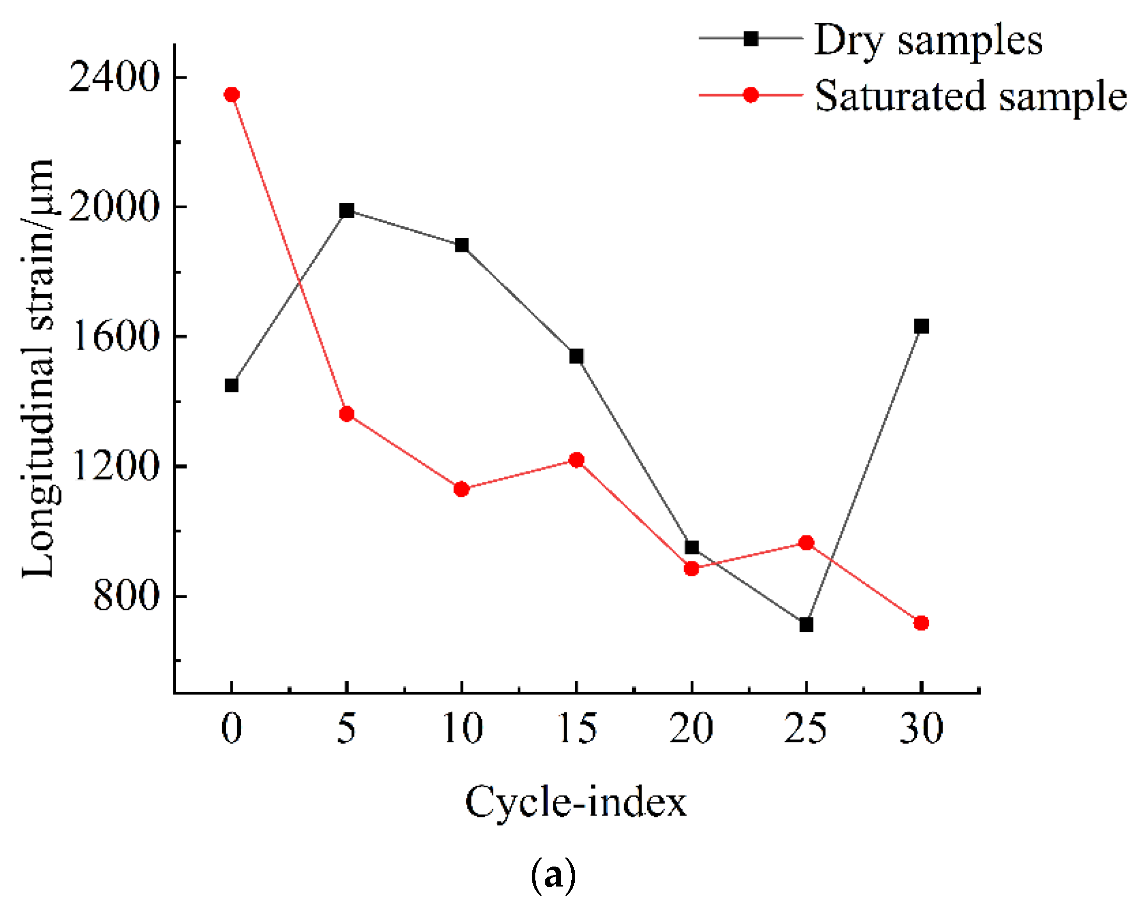
According to Table 4 and 
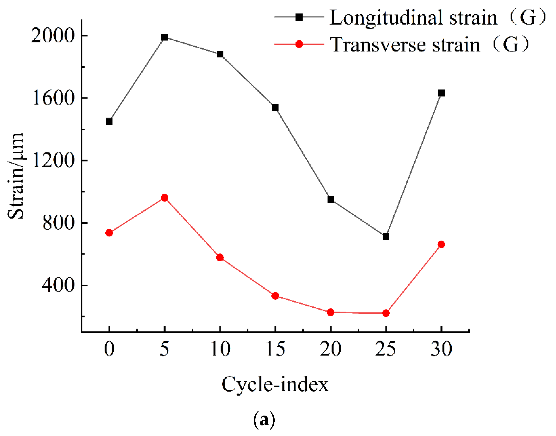
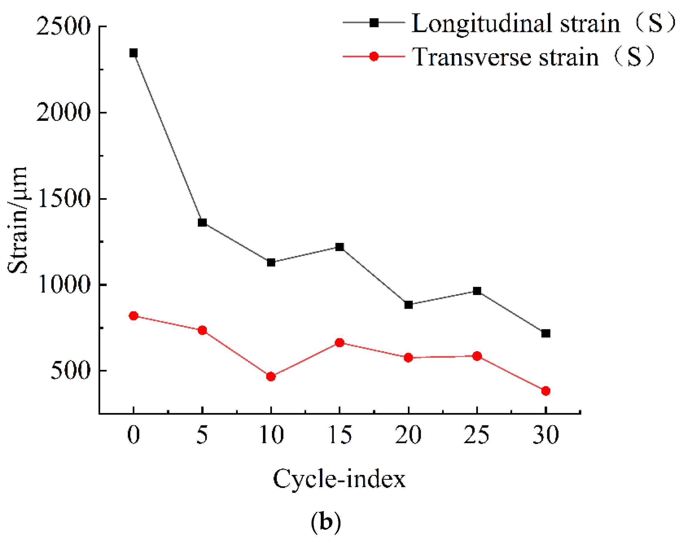
Figure 11a, with the increased number of freeze–thaw cycles, the strain during dry sample damage first increased, then decreased, and finally increased, with longitudinal strain greater than transverse strain. During the first five freeze–thaw cycles, the strain during dry sample damage increased with the number of freeze–thaw cycles. The number of damaged cycles decreased with the increase of cycles from the 5th to the 25th cycle and rose again after the 25th cycle.
As shown in Figure 11b, the strain of immersion-saturated sample destruction decreased gradually with the increase of freeze–thaw cycles, and the longitudinal strain was significantly more significant than the transverse strain. However, the strain change rate was substantial during the first ten freeze–thaw cycles, and the curve remained unchanged after the 10th cycle. Since strain would not decrease infinitely with the increase of the cycle number, we predicted that after a specific number of freeze–thaw cycles, the damaging strain of the immersion-saturated rock samples no longer significantly changed with the increase of the number of freeze–thaw cycles and appeared to be stable.
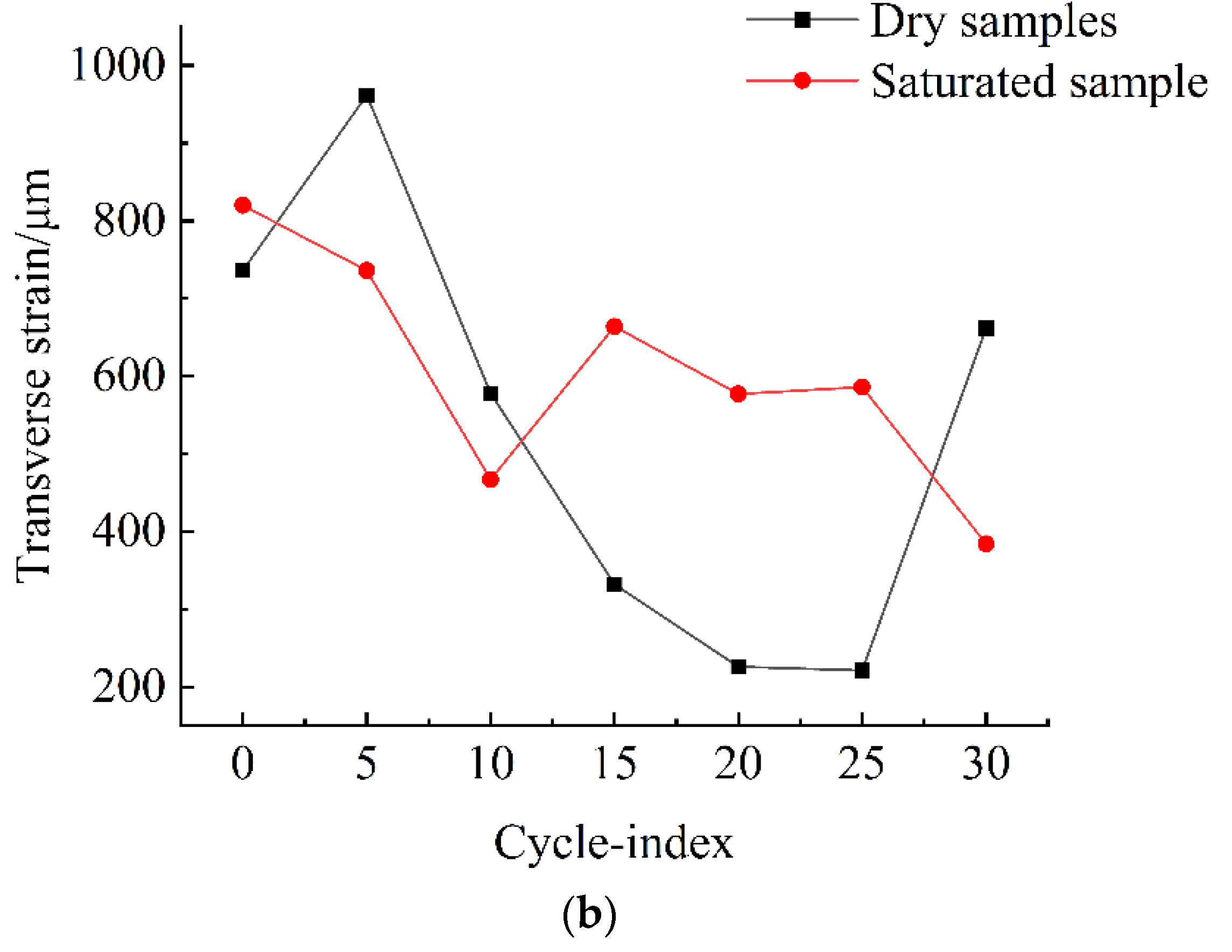
According to the comparison of the number of freeze–thaw cycles and the longitudinal and transverse strains during rock samples destruction (Figure 12a,b), the longitudinal strain, in general, was more significant than the immersion-saturated sample when the dry sample was damaged. However, between the 5th and 25th cycle, the longitudinal strain decreased with the increase in the number of freeze–thaw cycles.
As shown in Figure 12b, when the number of freezing–thawing cycles is less than 11, the transverse strain is more significant than that of the immersion-saturated sample when the dry sample fails. After the 11th cycle, the transverse strain upon the failure of the immersion-saturated rock samples was more significant than that of the dry sample as the number of freeze–thaw cycles. Moreover, the transverse strain, in general, decreased with the number of freeze–thaw cycles.
According to Table 5 and 
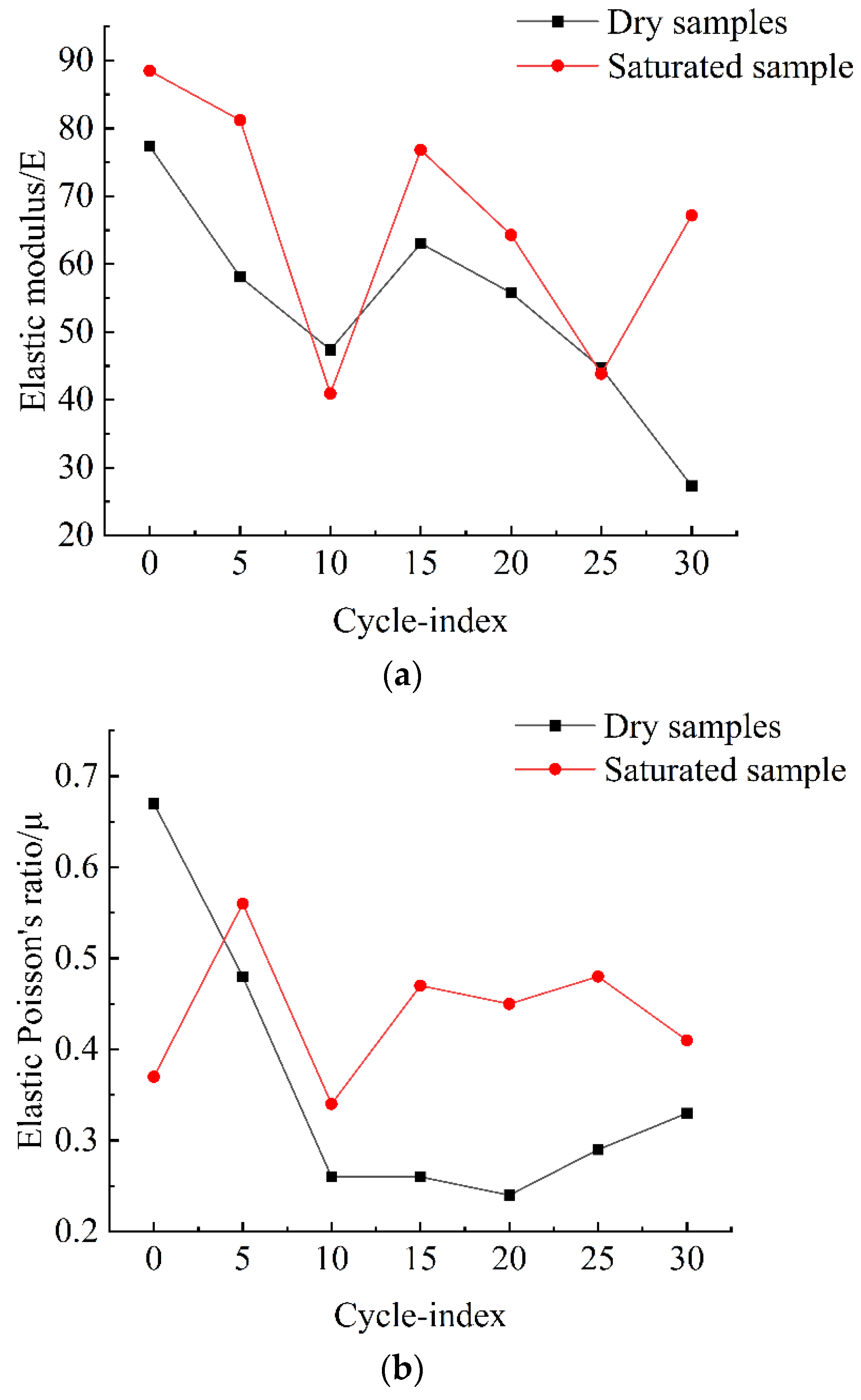
Figure 13a,b, freeze–thaw cycling impacts the rock elastic modulus and Poisson’s ratio.
As shown in Figure 13a, the elastic modulus of the immersion-saturated rock samples is slightly greater than that of the dry sample, and as the number of freeze–thaw cycles increases, the elastic modulus of both samples decreases. Before the first ten freeze–thaw cycles, the reduction in the elastic modulus of both samples was slightly more significant than the reduction after the 10th cycle; between the 10th and 15th cycles, the elastic moduli of both samples increased with the increase of the number of freeze–thaw cycles but decreased after the 15th cycle.
Figure 13b shows that immersion-saturated rock samples have a higher elastic Poisson’s ratio than dry samples. Before the first ten freeze–thaw cycles, the elastic Poisson’s ratios of the two samples decreased rapidly. However, after the first ten freeze–thaw cycles, the elastic Poisson’s ratios of both samples tended to be stable.
The analysis predicted that after a certain number of freeze–thaw cycles, the Poisson’s ratios of the two samples would be stable. According to the test curve, as the number of freezing–thawing cycles increased, the Poisson’s ratio of the dry rock sample approached 0.6–0.7 eventually. In contrast, the elastic Poisson’s ratio of the immersion-saturated sample would have a final elastic Poisson’s ratio of 0.45.
According to Table 6 and 
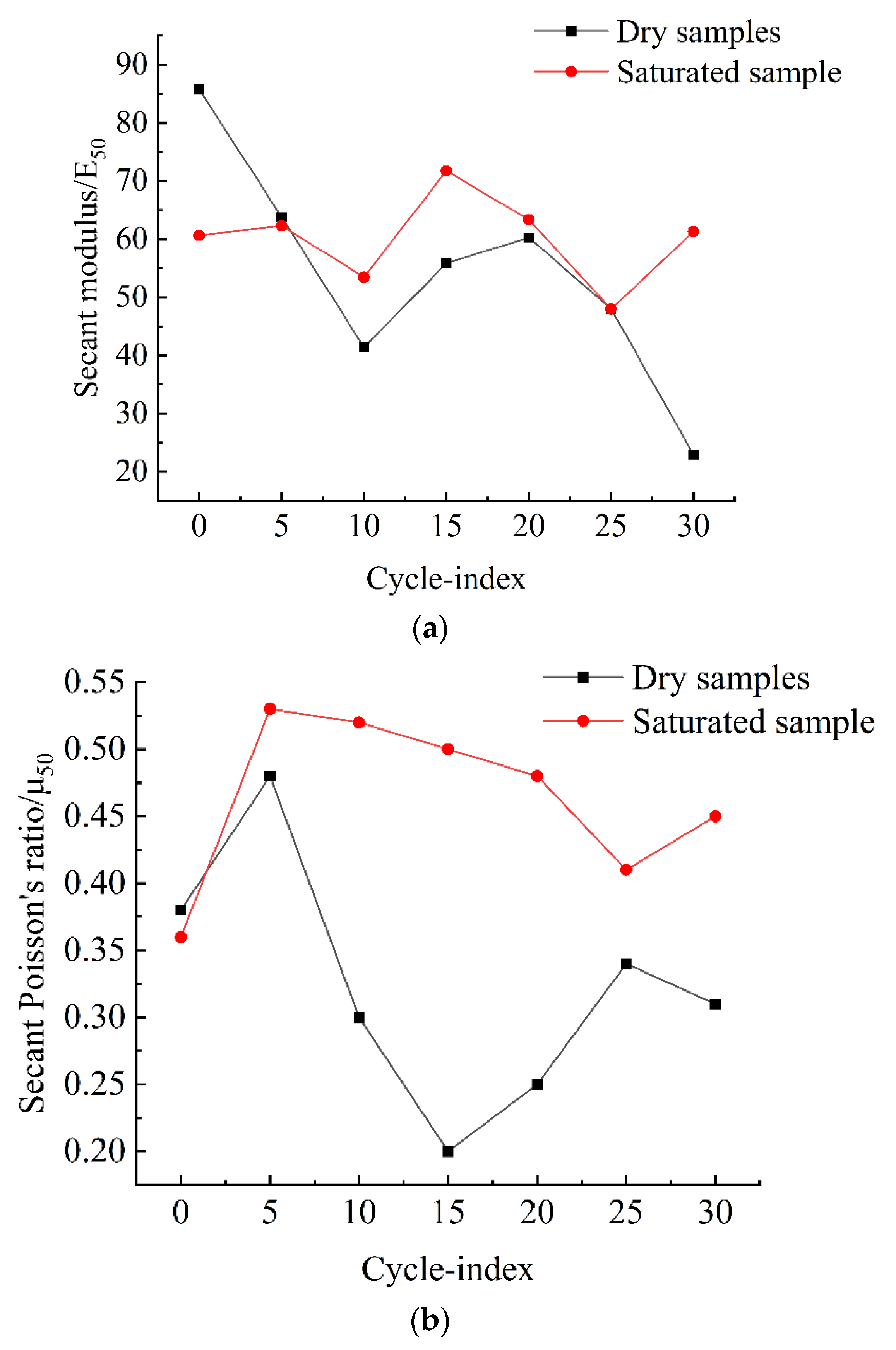
Figure 14a,b, freeze–thaw cycling impacted the secant modulus and secant Poisson’s ratio of rock.
As shown in Figure 14a, as the number of freeze–thaw cycles increased, the secant modulus of the immersion-saturated sample was slightly larger than that of the dry sample. The secant modulus of the two groups of rock samples decreased as the number of freeze–thaw cycles grew. Except for the fact that the secant modulus of the dry sample showed a slight increase during the 10th and 20th freeze–thaw cycles, it was continuously reducing with a gradually increasing gradient both when the freezing–thawing was within the first ten cycles and when the freeze–thaw was after the 20th cycle. However, the secant modulus of the immersion-saturated sample had a stable change during the freeze–thaw cycles.
As shown in the Figure 14b curve, the secant Poisson’s ratio of the immersion-saturated sample was more significant than that of the dry sample and had a decreasing trend in general as the number of freeze–thaw cycles grew, because the secant Poisson’s ratio of the dry sample had a significant rate of increase as the number of freeze–thaw cycles increased. In contrast, the rate of increase of the immersion-saturated sample was relatively low.
The effect of freeze–thaw cycles changed the nature of the rock, and the specimens containing fractures were eliminated after the pre-screening sample, so it is considered that the effect of water on fractures in freeze–thaw cycles is small, and it is considered that the freeze–thaw cycles changed the nature of the rock’s own strength by this test, and the strength deterioration of the specimens gradually increased with the increase of the number of freeze–thaw cycles, showing the phenomenon that the uniaxial compressive strength of the rock gradually decreased with the increase of the number of freeze–thaw cycles.
According to the loading direction, the specimens were mainly loaded along the longitudinal direction when the ring was broken, so the longitudinal strain was always greater than the transverse strain when the damage occurred. After the specimens were immersed in water, the modulus of elasticity and Poisson’s ratio changed, their brittleness changed, and their elastic phase at the time of destruction increased, so the strain value at the time of destruction of the immersed specimens increased. As the number of freeze–thaw cycles increases, the uniaxial compressive strength of the rock gradually decreases, so the longitudinal loading displacement gradually decreases, and the corresponding damage strain also decreases with the number of freeze–thaw cycles.

3.4. Summary and Analysis of Test Data

After the samples had the freeze–thaw cycles, we found that most physical and mechanical parameters of samples decreased as the number of freeze–thaw cycles increased.
Wang et al. [40] found that rock’s compressive strength and wave velocities were significantly positively correlated. The variation rules of different rock types were similar to their characteristics. This experimental study again confirmed the relationship between compressive strength and wave velocities. The modulus and Poisson’s ratio decreased after freeze–thaw cycles, indicating that the elastic behavior of rocks decreased gradually and shortened the elasticity range. This law could be explained again by the decrease of strain, secant modulus, and secant Poisson’s ratio upon failure. In other words, with the increasing number of freeze–thaw cycles, the wave velocity of rock gradually decreased, while the strength parameters also decayed. However, the influence of freeze–thaw cycling on the strength of the surrounding rock had a specific limit. On exceeding the influence limit of freeze–thaw cycling, the strength parameters ceased changing even if the number of freeze–thaw cycles continued to grow.

4. Conclusions and Discussion for Further Research

4.1. Conclusions

Based on the testing of two sets of tuff samples in this study, the uniaxial compressive strength, shear wave velocity, and amplitude, as well as the longitudinal strain, transverse strain, elastic modulus, Poisson’s ratio, secant modulus, and secant Poisson’s ratio upon failure were found affected by the freeze–thaw cycles. Furthermore, the following additional conclusions were evident as the number of freeze–thaw cycles grew:
(1)
When the temperature was between −40 °C and 40 °C, the rock temperature had a rate of increase 2.57 times greater than that of decrease.
(2)
The shear wave velocity of two rock groups decreased as the number of freeze–thaw cycles grew. Meanwhile, the samples’ uniaxial compressive strength, elastic modulus, Poisson’s ratio, secant modulus, and secant Poisson’s ratio showed a reduction.
(3)
Transverse strain of the two groups was more petite than the longitudinal strain, while the longitudinal strain of the dry sample was more significant than the immersion-saturated sample. Furthermore, it showed a trend of first increasing, then decreasing, and then increasing. On the other hand, longitudinal and transverse strains of the immersion-saturated sample showed a decreasing trend when it failed.
(4)
As the number of freeze–thaw cycles increased, the wave velocity of rock gradually decreased, and all strength parameters of rock also decayed. However, the influence of freeze–thaw cycling on the strength of the surrounding rock also had a specific limit. When the influence limit of freeze–thaw cycling was exceeded, the strength parameters of the surrounding rock would no longer change with the increase in the number of freeze–thaw cycles.
(5)
We believe that freeze–thaw cycles lead to deterioration of tuff strength. The reason for this phenomenon is that we believe that the freeze–thaw cycling action changes the rock internally, affecting its density, which, in turn, causes a decay in strength, etc.

4.2. Discussion for Future Research

This experiment focused on studying the strong attenuation of surrounding rocks at the tunnel entrance/exit after freeze–thaw cycles. The variation rules of wave velocity, uniaxial compressive strength, and related parameters with the number of freeze–thaw cycles were summarized. However, this test only discussed the two groups’ changes in sample parameters after the first 30 freeze–thaw cycles. Although the number of experimental groups in this study met the specification requirements, there was still a particular dispersion in the test results.
Based on the tests, we verified the influence of freeze–thaw cycling on the strength parameters of surrounding rocks in the later stage. Through this study, we realized that the following problems needed further investigation:
(1)
After how many freeze–thaw cycles will the strength parameters of rock no longer have large fluctuations?
(2)
Strength parameters of the surrounding rock will be stable after reaching the influence limit of freeze–thaw cycling. What is the relationship between the value and the initial index of surrounding rock strength parameters of surrounding rocks?
Therefore, from an engineering standpoint, the strength degradation of the surrounding rock at the tunnel entrance/exit should consider the impact of the freeze–thaw cycles induced by the local environment. Therefore, this study helped prevent the effects of strong attenuation of surrounding rocks caused by freeze–thaw cycling to a certain extent, thus avoiding specific engineering problems. Meanwhile, this study provided a theoretical basis for covering the stability control of the surrounding rock at the tunnel entrance/exit in the high-altitude mountainous area. The study in this paper is only applicable to the studied tuff stratum.

Author Contributions

Conceptualization, Z.G. and Z.Z.; methodology, Z.G. and Z.Z.; software, Y.Z. and G.S.; validation, Z.G. and Z.Z.; formal analysis, Z.G. and Z.Z.; investigation, Y.Z. and G.S.; resources, Z.Z.; data curation, Z.G. and Y.Z.; writing—original draft preparation, Z.G. and G.S.; writing—review and editing, Z.Z. and Y.Z.; visualization, Z.G.; supervision, Z.Z. and G.S.; project administration, Z.Z.; funding acquisition, Z.Z. All authors have read and agreed to the published version of the manuscript.

Funding

This research was funded by the Xinjiang Uygur Autonomous Region Special Program for Key R&D Tasks (2021B03004), State Key Laboratory for Geo Mechanics and Deep Underground Engineering, China University of Mining & Technology (SKLGDUEK2028).

Institutional Review Board Statement

Not applicable.

Informed Consent Statement

Not applicable.

Data Availability Statement

The data used to support the findings of this study are included within the manuscript.

Acknowledgments

Thanks to everyone who contributed to this article.

Conflicts of Interest

The authors declare no conflict of interest.

References

  1. Tian, J.; Yang, G.; Liu, H. Study on the freezing damage mechanism and its prevention in cold region rock tunnel. Chin. J. Undergr. Space Eng. 2007, 3 (Suppl. S2), 1484–1489. [Google Scholar]
  2. Lai, Y.; Wu, H.; Wu, Z. Analytical viscoelastic solution for frost force in cold-region tunnels. Cold Reg. Sci. Technol. 2000, 31, 227–234. [Google Scholar] [CrossRef]
  3. Li, G.; Huang, Y. Study on viscous debris flow rate of high altitude alpine highway in Xinjiang. Sci. Technol. Inf. 2008, 27, 50–76. [Google Scholar]
  4. Huang, Y.; Yang, S.; Zhou, Y.; Chen, H. Research on prevention and control of slope debris flow on alpine high altitude mountain roads. Resour. Environ. Eng. 2009, 23 (Suppl. S1), 107–110. [Google Scholar]
  5. Geng, W. Prevention and control measures of salivary ice disease on high altitude cold mountain roads. Build. Mater. Decor. 2018, 17, 222–223. [Google Scholar]
  6. Hu, Y. Evaluation of Geological Hazards of Mountain Roads. Master’s Thesis, Xi’an University of Science and Technology, Xi’an, China, 2017. [Google Scholar]
  7. Zhang, Z.; Lin, L. Key points of roadbed design in alpine and high-altitude snow-affected areas. Eng. Constr. 2016, 30, 473–475. [Google Scholar]
  8. He, E.; Li, S.; He, Y. Safety evaluation and guarantee measures for alpine high altitude mountain roads. Highw. Transp. Technol. (Appl. Technol. Ed.) 2016, 12, 273–276. [Google Scholar]
  9. Yao, X. Research on Crack Resistance of Semi-Rigid Subgrade for High Altitude Mountain Roads. Master’s Thesis, Chongqing Jiaotong University, Chongqing, China, 2017. [Google Scholar]
  10. Yavuz, H.; Altindag, R.; Sarac, S. Estimating the index properties of deteriorated carbonate rocks due to freeze-thaw and thermal shock weathering. Int. J. Rock Mech. Min. Sci. 2006, 43, 767–775. [Google Scholar] [CrossRef]
  11. Momeni, A.; Abdilor, Y.; Khanlari, G.R. The effect of freeze-thaw cycles on physical and mechanical properties of granitoid hard rocks. Bull. Eng. Geol. Environ. 2015, 75, 1649–1656. [Google Scholar] [CrossRef]
  12. Ghobadi, M.H.; Babazadeh, R. Experimental Studies on the Effects of Cyclic Freezing-Thawing, Salt Crystallization, and Thermal Shock on the Physical and Mechanical Characteristics of Selected Sandstones. Rock Mech. Rock Eng. 2014, 48, 1001–1016. [Google Scholar] [CrossRef]
  13. Yamabe, T.; Neaupane, K.M. Determination of some thermo-mechanical properties of Sirahama sandstone under subzero temperature condition. Int. J. Rock Mech. Min. Sci. 2001, 38, 1029–1034. [Google Scholar] [CrossRef]
  14. Fahey, B.D. Frost action and hydration as rock weathering mechanisms on schist: Alaboratory study. Catena 1995, 25, 7–20. [Google Scholar] [CrossRef]
  15. Matsuoka, N. Mechanisms of rock breakdown by frost action: An experimental approach. Cold Reg. Sci. Technol. 1990, 17, 253–270. [Google Scholar] [CrossRef]
  16. Liu, H.; Niu, F.; Xu, Z. Experimental study on the physical and mechanical properties of andesite and granite under cyclic freeze-thaw conditions. Glacial Permafr. 2011, 33, 231–237. [Google Scholar]
  17. Wan, Y. Study on Freeze-Thaw Damage Characteristics and Tunnel Stability of Quantai Tunnel. Master’s Thesis, Jilin University, Jilin, China, 2020. [Google Scholar]
  18. Xu, G.; Liu, Q.; Peng, W. Experimental study of basic mechanical properties of rocks under low temperature. J. Rock Mech. Eng. 2006, 25, 2502–2508. [Google Scholar]
  19. Xu, G.; Liu, Q. Analysis of freeze-thaw damage mechanism and freeze-thaw mechanics of rocks. J. Rock Mech. Eng. 2005, 24, 3076–3082. [Google Scholar]
  20. Rong, Z. Analysis and Evaluation of Stability of Rocky and Steep Slopes in Alpine Mines. Master’s Thesis, China University of Geosciences, Wuhan, China, 2010. [Google Scholar]
  21. Zhang, H.; Yang, Q. Experimental freeze-thaw mechanics and damage extension characteristics of rocks. J. China Univ. Min. Technol. 2011, 40, 123–126. [Google Scholar]
  22. Liu, C. Study on the Mechanism of Freeze-Thaw Damage in the Surrounding Rock of Houwaizi Tunnel in the Seasonal Freezing Zone. Master’s Thesis, Jilin University, Jilin, China, 2020. [Google Scholar]
  23. Inada, Y.; Yokota, K. Some Studies of Low Temperature Rock Strength. Int. J. Rock Mech. Min. Sci. Geomech. Abstr. 1984, 21, 145–153. [Google Scholar] [CrossRef]
  24. Tang, M.; Xu, Q.; Deng, W. Deterioration law of typical rock mechanical properties of Sichuan-Tibet Railway under freeze-thaw and loading-unloading conditions. Earth Sci. 2022, 47, 1917–1931. [Google Scholar]
  25. Hou, Z. Study on Freeze-Thaw Mechanical Properties of Fractured Rock and Its Stability of Mine Slope in High Altitude Cold Area. Master’s Thesis, University of Science and Technology Beijing, Beijing, China, 2022. [Google Scholar]
  26. Shen, X. Freeze-Thaw Cycle Characteristics and Deterioration Damage Mechanism of Slope Rock. Master’s Thesis, Changjiang Academy of Sciences, Wuhan, China, 2020. [Google Scholar]
  27. Wu, Y. Study on Strength, Damage and Creep Properties of Rock-Like Materials under Freeze-Thaw Cycles. Ph.D. Thesis, Qingdao University of Science and Technology, Qingdao, China, 2018. [Google Scholar]
  28. Jiang, S. Research on Physical and Mechanical Properties and Damage Characteristics of Freeze-Thaw Rocks in Alpine Mountains. Master’s Thesis, Chengdu University of Technology, Chengdu, China, 2016. [Google Scholar]
  29. Liu, H.; Zhao, Y. Theoretical calculation of freeze-swelling force in tunnel surrounding rock under freeze-thaw cycle. J. Cent. South Univ. (Nat. Sci. Ed.) 2020, 51, 1049–1058. [Google Scholar]
  30. Zhang, H.; Yang, Q. Study of rock damage model under coupled freeze-thaw and load. J. Rock Mech. Eng. 2010, 29, 471–476. [Google Scholar]
  31. Sayevand, K.; Arab, H. A fresh view on particle swarm optimization to develop a precise model for predicting rock fragmentation. Eng. Comput. 2019, 36, 533–550. [Google Scholar] [CrossRef]
  32. Bost, M.; Pouya, A. Stress generated by the freeze-thaw process in open cracks of rockwalls: Empirical model for tight limestone. Bull. Eng. Geol. Environ. 2017, 74, 1491–1505. [Google Scholar] [CrossRef] [Green Version]
  33. Ince, I.; Fener, M. A prediction model for uniaxial compressive strength of deteriorated pyroclastic rocks due to freeze-thaw cycle. J. Afr. Earth Sci. 2016, 120, 134–140. [Google Scholar] [CrossRef]
  34. Al-Omari, A.; Brunetaud, X.; Beck, K. Effect of thermal stress, condensation and freezing-thawing action on the degradation of stones on the Castle of Chambord, France. Environ. Earth Sci. 2013, 71, 3977–3989. [Google Scholar] [CrossRef]
  35. Wang, M.; Zhu, Z.; Dong, Y. Study of mixed-mode I/II fractures using single cleavage semicircle compression specimens under impacting loads. Eng. Fract. Mech. 2017, 177, 33–44. [Google Scholar] [CrossRef]
  36. Wang, M.; Wang, F.; Zhu, Z. Modelling of crack propagation in rocks under SHPB impacts using a damage method. Fatigue Fract. Eng. Mater. Struct. 2019, 38, 1139–1148. [Google Scholar] [CrossRef]
  37. Wang, F.; Wang, M.; Nezhad, M. Rock Dynamic Crack Propagation under Different Loading Rates Using Improved Single Cleavage Semi-Circle Specimen. Appl. Sci. 2019, 9, 4944. [Google Scholar] [CrossRef] [Green Version]
  38. Niu, C.; Zhu, Z.; Zhou, L. Study on the microscopic damage evolution and dynamic fracture properties of sandstone under freeze-thaw cycles. Cold Reg. Sci. Technol. 2021, 191, 103328. [Google Scholar] [CrossRef]
  39. Zhu, G.; Gui, C.; Xiong, X. Density versus longitudinal and transverse wave velocity relationships. J. Geophys. 1995, 38 (Suppl. S1), 260–264. [Google Scholar]
  40. Wang, R.; Ren, M.; Liu, J. Correlation study of rock wave velocity and strength parameters. Min. Res. Dev. 2021, 41, 87–91. [Google Scholar]
Figure 1. Schematic diagram of the location of the study area.
Sustainability 14 09305 g001
Figure 2. On-site sampling and photos of some samples. (a) Drilling sampling, (b) Sample.
Sustainability 14 09305 g002
Figure 3. Freeze–thaw cycle test temperature change curve.
Sustainability 14 09305 g003
Figure 4. Schematic diagram of wave speed test.
Sustainability 14 09305 g004
Figure 5. Schematic diagram of resistance strain gauge.
Sustainability 14 09305 g005
Figure 6. Uniaxial compression test.
Sustainability 14 09305 g006
Figure 7. Image of sample changes in different freeze–thaw cycle stages. (a) Before freeze–thaw cycle, (b) After freeze–thaw cycle (Dry), (c) Melting process, (d) After freeze–thaw cycle (Wet).
Sustainability 14 09305 g007aSustainability 14 09305 g007b
Figure 8. Shear wave velocity-freeze–thaw cycles curve.
Sustainability 14 09305 g008
Figure 9. Shear wave amplitude-freeze–thaw cycles curve.
Sustainability 14 09305 g009
Figure 10. Freeze–thaw cycles—maximum load curve, maximum stress curve. (a) Cycle-index and Maximum load, (b) Cycle-index and Maximum stress.
Sustainability 14 09305 g010
Figure 11. Freeze–thaw cycles-failure strain curve. (a) Dry samples strain curve, (b) Saturated samples strain curve.
Sustainability 14 09305 g011aSustainability 14 09305 g011b
Figure 12. Freeze–thaw cycles-failure strain comparison curve. (a) Longitudinal strain curve, (b) Transverse strain curve.
Sustainability 14 09305 g012aSustainability 14 09305 g012b
Figure 13. Freeze–thaw cycles-elastic modulus curve, elastic Poisson’s ratio curve. (a) Elastic modulus curve, (b) Elastic Poisson’s ratio curve.
Sustainability 14 09305 g013
Figure 14. Freeze–thaw cycles-secant modulus curve, secant Poisson’s ratio curve. (a) Secant modulus curve, (b) Secant Poisson’s ratio curve.
Sustainability 14 09305 g014
Table 1. The sample groups.
Cycle-Index051015202530
Dry samples groupsG1G2G3G4G5G6G7
Saturated sample groupsS1S2S3S4S5S6S7
Table 2. Freeze–thaw cycles and shear wave velocity results data table.
Cycle-IndexGroup No.T/μsA/mvV/km·s−1
0G118.70.295.348
5G218.70.395.348
10G320.10.284.975
15G419.90.235.025
20G520.30.244.926
25G622.00.184.545
30G720.30.174.926
0S120.30.214.926
5S220.90.244.785
10S321.40.194.673
15S421.20.174.717
20S522.00.204.545
25S621.70.184.608
30S721.80.174.587
Table 3. Freeze–thaw cycles and maximum load, maximum stress data table.
Cycle-IndexGroup No.Maximum Load/kNMaximum Stress/MPa
0G1269,362.2500137.1851
5G2316,925.4000161.4088
10G3209,809.1000106.8549
15G4250,503.1000127.5802
20G5155,875.800079.3869
25G683,218.765642.3830
30G7105,022.648453.4876
0S1424,275.7813216.0819
5S2244,133.1651124.3360
10S3128,023.953165.2021
15S4282,091.4583143.6680
20S5159,700.899081.3350
25S6107,604.400054.8025
30S7133,001.500067.7371
Table 4. Freeze–thaw cycles and longitudinal strain, transverse strain data table.
Cycle-IndexGroup No.Longitudinal Strain/μmTransverse Strain/μm
0G11451.00 736.00
5G21990.00 962.00
10G31882.00 578.00
15G41540.00 332.00
20G5950.00 226.00
25G6712.00 221.00
30G71633.00 662.00
0S12348.00 820.00
5S21362.00 736.00
10S31130.00 467.00
15S41220.00 664.00
20S5885.00 577.00
25S6964.00 586.00
30S7717.00 384.00
Table 5. Freeze–thaw cycles, elastic modulus, elastic Poisson’s ratio data table.
Cycle-IndexGroup No.Elastic ModulusElastic Poisson’s Ratio
0G177.34 0.67
5G258.11 0.48
10G347.37 0.26
15G463.04 0.26
20G555.75 0.24
25G644.69 0.29
30G727.33 0.33
0S188.47 0.37
5S281.20 0.56
10S340.93 0.34
15S476.81 0.47
20S564.30 0.45
25S643.84 0.48
30S767.18 0.41
Table 6. Freeze–thaw cycles, secant modulus, secant Poisson’s ratio data table.
Cycle-IndexGroup No.Secant ModulusPoisson’s Ratio
0G185.74 0.38
5G263.80 0.48
10G341.40 0.30
15G455.83 0.20
20G560.28 0.25
25G647.99 0.34
30G722.92 0.31
0S160.66 0.36
5S262.31 0.53
10S353.47 0.52
15S471.76 0.50
20S563.36 0.48
25S647.98 0.41
30S761.32 0.45
Publisher’s Note: MDPI stays neutral with regard to jurisdictional claims in published maps and institutional affiliations.

