Characterization of GNSS Signals Tracked by the iGMAS Network Considering Recent BDS-3 Satellites


1
GNSS Research Center, Wuhan University, Wuhan 430079, China
2
Faculty of Information Engineering, China University of Geosciences, Wuhan 430074, China
*
Author to whom correspondence should be addressed.
Remote Sens. 2018, 10(11), 1736; https://0-doi-org.brum.beds.ac.uk/10.3390/rs10111736
Submission received: 19 September 2018
/
Revised: 20 October 2018
/
Accepted: 31 October 2018
/
Published: 3 November 2018
(This article belongs to the Special Issue Environmental Research with Global Navigation Satellite System (GNSS))
Abstract
:The international GNSS monitoring and assessment system (iGMAS) tracking network has been established by China to track multi-GNSS satellites. A key feature of iGMAS stations is the capability to fully track new navigation signals from the recently deployed BDS-3 satellites. In addition to the B1I and B3I signals inherited from BDS-2 satellites, the BDS-3 satellites are capable of transmitting new open service signals, including B1C at 1575.42 MHz, B2a at 1176.45 MHz, and B2b at 1207.14 MHz. In this contribution, we present a comprehensive analysis and characterization of GNSS signals tracked by different receivers and antennas equipped in the iGMAS network, especially as they relate to BDS-3 signals. Signal characteristics are analyzed in terms of the carrier-to-noise density ratio for the different signals as measured by the receiver, as well as pseudo-range noise and multipath. Special attention is given to discussion of the satellite-induced code bias, which has been identified to exist in the code observations of BDS-2, and the inter-frequency clock bias (IFCB), which has been observed in the triple-frequency carrier phase combinations of GPS Block IIF and BDS-2 satellites. The results indicate that the satellite-induced code bias is negligible for all signals of BDS-3 satellites, while small IFCB variations with peak amplitudes of about 1 cm can be recognized in BDS-3 triple-carrier combinations.
1. Introduction
With the rapid development of the global navigation satellite system (GNSS), the China Satellite Navigation Office has initiated the international GNSS Monitoring and Assessment System (iGMAS) to monitor and assess the performance and operational status of the Chinese BeiDou Navigation Satellite System (BDS), as well as to promote compatibility and interoperability among different GNSS constellations [1,2]. As a backbone of iGMAS, a network of multi-GNSS monitoring stations has been set up around the globe to track multi-GNSS satellites. Several research institutions have been selected as analysis centers to process collected GNSS observation data and provide satellite orbits, clocks, and other kinds of information. There are currently 23 stations in the iGMAS network. A key feature of iGMAS stations is the capability to track new BDS signals from recently deployed global system satellites.
The development of BDS is divided into three phases: the demonstration system (BDS-1), the regional system (BDS-2), and the global system (BDS-3) [3,4]. BDS-1 was completed with two geostationary (GEO) satellites and a backup satellite in 2003. BDS-2 consists of five GEO, five inclined geostationary orbit (IGSO) satellites, and four medium earth orbit (MEO) satellites, and has been providing official positioning, navigation and timing services over the Asia-Pacific area since December 27, 2012. Each of the BDS-2 satellites transmits signals in quadrature phase-shift keying (QPSK) modulation on three frequency bands, namely B1I at 1561.098 MHz, B2I at 1207.14 MHz, and B3I at 1268.52 MHz. BDS-3 is expected to provide greatly improved services to global users with 3 GEO, 3 IGSO, and 24 MEO satellites by 2020.
By February 2016, five experimental BDS-3 satellites (hereafter, abbreviated to BDS-3e), including two IGSO and three MEO satellites, had completed deployment with the task of testing various key technologies for upcoming BDS-3, including new types of navigation signals, inter-satellite links, and onboard frequency standards. During the past two years, many studies have been carried out to investigate various aspects of these BDS-3e satellites, including signal quality analysis [5], precise orbit determination (POD) [6], performance of satellite clocks [7], precise point positioning (PPP) [8], and relative positioning [5]. Since the iGMAS stations support BDS-3 signal tracking, the majority of studies of the BDS-3e satellites were based on the data collected by the iGMAS tracking network. Tan et al. [9] conducted initial POD of BDS-3e satellites using observations of nine iGMAS stations, and the orbit overlap precision for IGSO and MEO satellites is approximately 10 cm and 40 cm, respectively, in the radial component. Zhang et al. [10] comprehensively analyzed the satellite-induced code bias for BDS-3e satellites using data from iGMAS stations. Li et al. [11] estimated the differential code biases (DCBs) of BDS-3e using iGMAS observations and evaluated the performance of both satellite and receiver DCBs, with results indicating that the estimated DCBs of BDS-3e satellites are more stable than those of BDS-2. In terms of satellite signals, Xiao et al. [12] analyzed the navigation signals transmitted by the M2-S satellite with the help of a 7.3-m high-gain antenna. Zhang et al. [5] performed quality assessment for four BDS-3e satellites using tracking data of only one station, including old B1I and B3I signals and new open service signals, namely B1C, B2a and B2b. In Yang et al. [13], B2a+b and S-band Bs signals transmitted by BDS-3e satellites were also included in quality analysis, which indicated that the B2a+b signal has the best performance.
It is worth noting that the BDS-3e satellites would not serve as a part of the BDS-3 constellation, but as a complement to the BDS-2 constellation with the termination of the validation task. At the end of 2017, China launched two BDS-3 satellites into space. The satellites were aboard a Long March-3B carrier rocket which launched from Xichang Satellite Launch Center, China. Up to June 2018, eight BDS-3 MEO satellites (excluding experimental satellites) have been successfully launched followed by extensive testing and evaluation. These satellites are manufactured by the China Academy of Space Technology (CAST) and the China Academy of Science (CAS). Some details of these eight BDS-3 satellites are listed in Table 1. It is noted that the PRN numbers of some satellites may be changed in the future. The ranging performance of a GNSS mainly depends on the measurement quality of the transmitted satellite navigation signals. Analysis of signal quality, measurement noise and multipath is critical for navigation systems [14]. Up to the present, only BDS-3e satellites have been analyzed. There has been a lack of reports conducted on the analysis of authentic BDS-3 satellite signals. In this study, we focus on the assessment and characterization of GNSS signals tracked by the iGMAS network, especially for the signals from the eight recently deployed BDS-3 satellites.
The paper is organized as follows. First, an overview of the iGMAS network with BDS-3 tracking capability is described. Then, the tracking characteristics of BDS-3, BDS-2, GPS, and Galileo signals are compared and discussed, including the carrier-to-noise density ratio and the pseudo-range multipath and errors. In the following section, we analyze the satellite-induced code biases for all the available signals of BDS-3. Finally, we present the results of triple-frequency carrier-phase combinations to investigate the inter-frequency clock biases.
2. Datasets
For BDS-3 satellites, signal design has been upgraded compared with BDS-2. In addition to the old B1I and B3I signals inherited from the BDS-2 satellites, several new open service signals are also transmitted by the BDS-3 satellites, namely, B1C at 1575.42 MHz, B2a at 1176.45 MHz, and B2b at 1207.14 MHz [12]. The B1C signal is compatible with GPS L1 and Galileo E1 signals; the B2a signal shares the same frequency as GPS L5 and Galileo E5a signals; and the B2b signal matches with the Galileo E5b signal. In addition, the BDS-3 B2b signal shares the same frequency as the BDS-2 B2 signal, but with a different modulation type. The frequencies, wavelengths and chip rates of BDS-2 and BDS-3 open service signals are listed in Table 2.
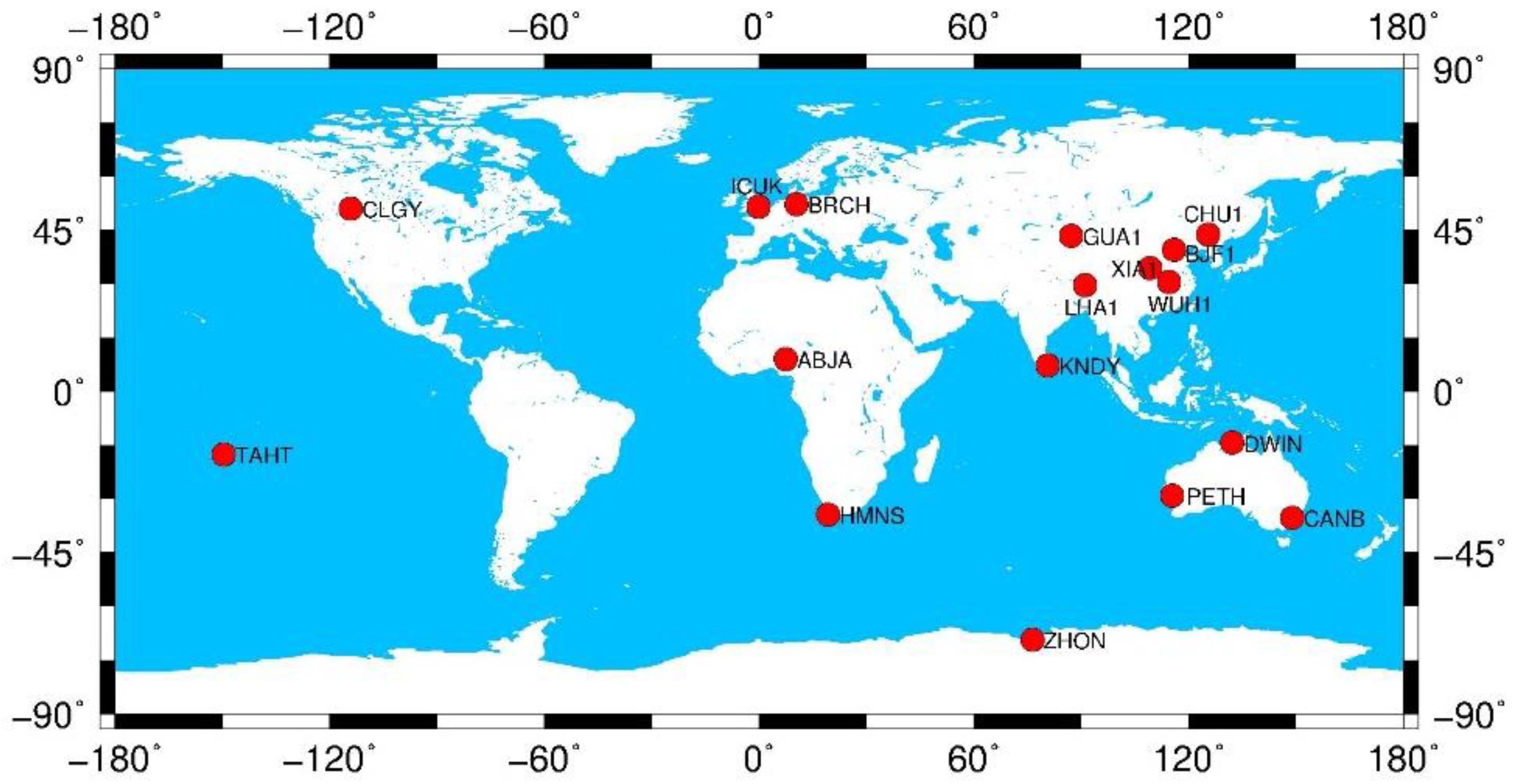
The iGMAS tracking network was developed by the China Satellite Navigation Office to track multi-GNSS observations and provide satellite orbits and clocks, station coordinates and many other kinds of information for users. At the time of this study, the iGMAS network consisted of 23 stations, 17 of which can track multi-GNSS satellites, including the recently deployed BDS-3 satellites. The distribution of these 17 stations is shown in Figure 1. Table 3 lists the configuration of these stations, which includes three different types of receivers and four different types of antennas. All receivers can simultaneously track GPS L1/L2/L5, Galileo E1/E5a/E5b, BDS-2 B1I/B3I, and BDS-3 B1I/B1C/B2a/B3I signals, and the GNSS_GGR receiver can additionally track BDS-3 B2b signals. Ten-day observation data collected by these stations from 28 May 2018 (DOY 148) to 6 June 2018 (DOY 157) are used for this study.
3. Methodology and Results
3.1. Carrier-To-Noise Density Ratio
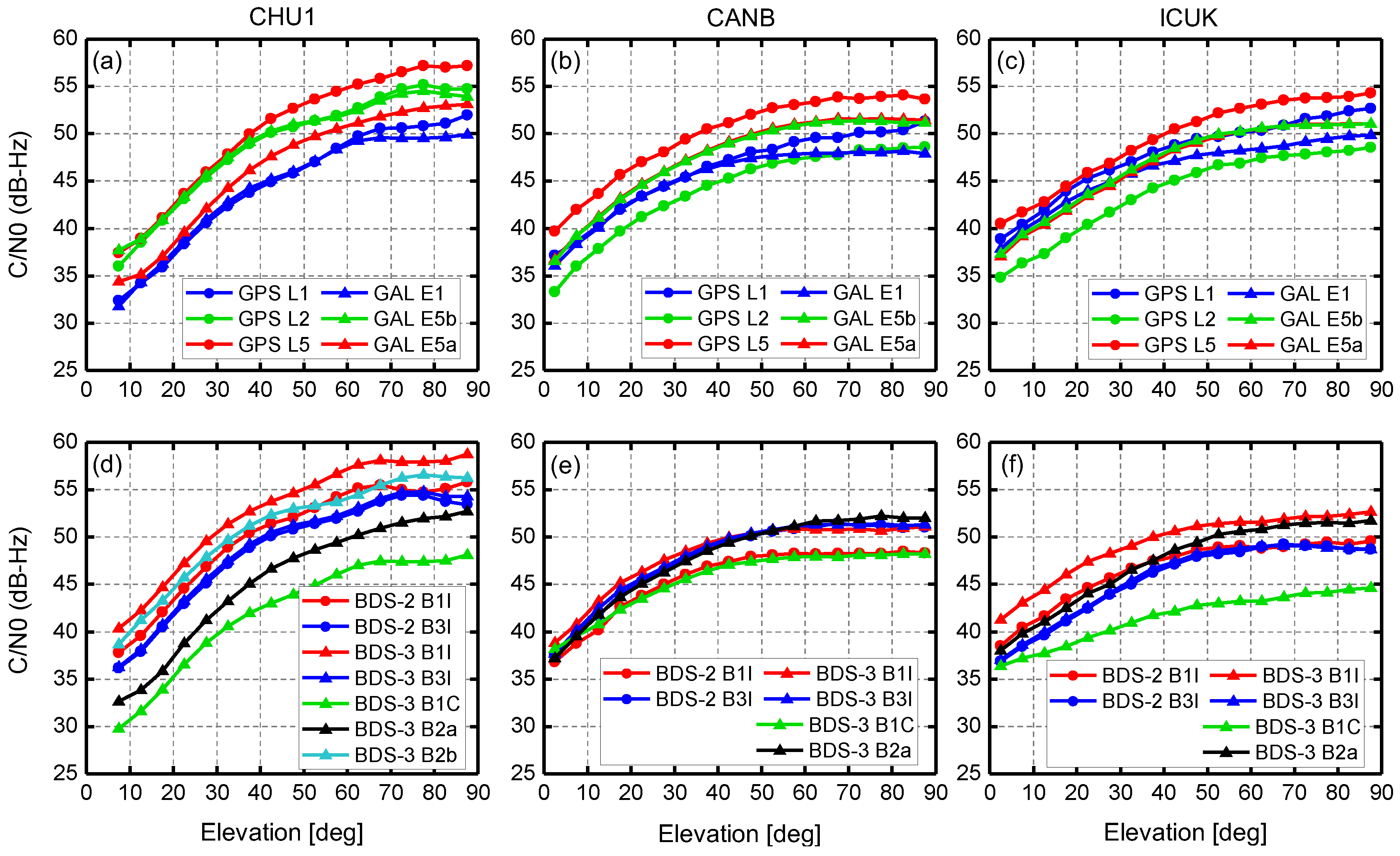
The carrier-to-noise density ratio (C/N0) and its variation with elevation provides a key figure of merit for the characterization of the wide variety of signals accessible with modern receivers. The observed C/N0 values of GPS, Galileo (GAL), and BDS-2 and BDS-3 signals at CHU1, CANB, and ICUK stations are depicted as a function of satellite elevation in Figure 2. These three stations are equipped with different receivers (Table 3). The CHU1 station can track BDS-3 B1I/B1C/B2a/B2b/B3I signals, while the CANB and ICUK stations are unable to track BDS-3 B2b signals. The GPS is restricted to Block IIF satellites that can simultaneously transmit L1/L2/L5 signals; the BDS-2 is confined to only MEO satellites (C11, C12, and C14) for comparison; and the BDS-3 involves the eight satellites listed in Table 1 and examined in this study. The tracking data for a period of ten days from DOY 148 to DOY 157 (2018) provide the basis for the analysis. For each station, we first group all C/N0 values according to their corresponding elevations separately for each signal of the selected GPS, Galileo, BDS-2, and BDS-3 satellites. Then, the C/N0 values within an elevation range of 5° are classified into one group. Finally, a mean value of C/N0 is computed and shown for each elevation group.
For GPS and Galileo in the top panels of Figure 2, it can be clearly seen that the GPS L5 signals exhibit the highest C/N0 values over the entire elevation range for each of the three stations. The CHU1 station shows distinctly different signal characteristics than the other two stations. On the whole, the Galileo E1 signal has the lowest power level at CHU1, while the GPS L2 signals have the lowest power levels at the CANB and ICUK stations. At the CANB and ICUK stations, the C/N0 values for all GPS and Galileo signals start at 34–40 dB-Hz at low elevation angles and reach 48–54 dB-Hz at zenith, while at the CHU1 station, the C/N0 values start at 32–38 dB-Hz at low elevation angles and reach 50–57 dB-Hz at zenith, and increase more quickly as elevation angle increases. For BDS-2 and BDS-3 in the bottom panels of Figure 2, it is clear that BDS-3 B1C signals exhibit the lowest C/N0 values for the three stations, especially CHU1 and ICUK, which is consistent with the results of BDS-3e satellite analysis in Zhang et al. [5] and Yang et al. [13]. For compatible signals (B1I/B3I) of BDS-2 and BDS-3, the B1I signals of BDS-3 are approximately 3 dB-Hz more powerful than those of BDS-2 for all three stations, while the B3I signals show almost the same C/N0 values for BDS-2 and BDS-3.
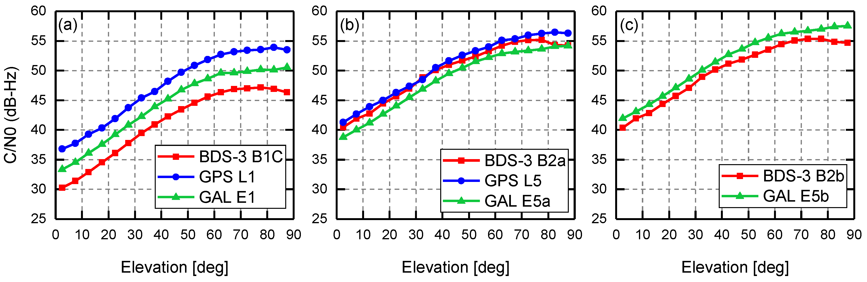
The new signals of BDS-3 share the same frequencies as some of GPS and Galileo signals. Figure 3 shows C/N0 values of these signals for BDS-3, GPS, and Galileo observed at ABJA station. For B1C/L1/E1 signals, the C/N0 values of GPS L1 signals are about 3 dB-Hz higher compared with Galileo E1, and about 6 dB-Hz higher compared with the BDS-3 B1C signal. For B2a/L5/E5a signals, the differences of their C/N0 values are within 2 dB-Hz. The GPS L5 signal is more powerful than the BDS-3 B2a signal, and the Galileo E5a signal is less powerful than the BDS-3 B2a. For B2b/E5b signals, the C/N0 values of the Galileo E5b signal are 1-2 dB-Hz higher than the BDS-3 B2b signal. There are also some differences for reported C/N0 values between stations (ABJA, CHU1) with the same receiver and antenna, which is inevitable as this is related to the environment, although signal strength is more affected by the hardware of the satellite and receiver. In addition, the observed C/N0 values could be affected by the tracking mode, and thus are not necessarily representative of the power level actually received from the satellites.
3.2. Pseudo-range Noise and Multipath
In order to analyze the pseudo-range noise and multipath errors, the multipath (MP) combination is computed as follows [15,16]:
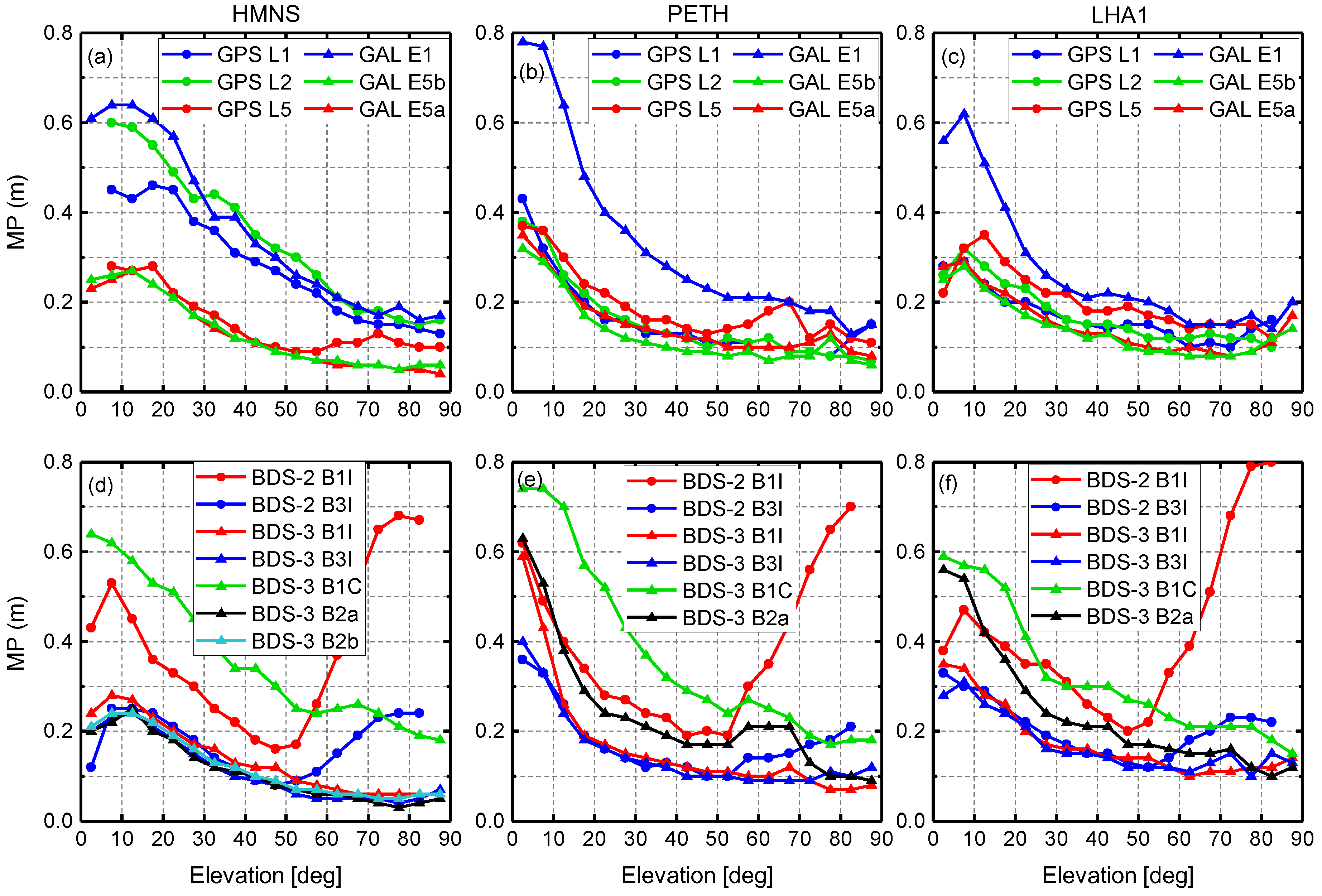
where the subscripts and indicate the carrier phase frequencies, is the code multipath of the signal , is the pseudo-range observation of signal , and are carrier phase observations (in meters), and is a bias that can be considered a constant if no cycle slip occurs on phase observations. The corresponding frequencies are and . This combination eliminates all errors except for receiver noise, multipath errors and bias variations in the pseudo-range observation. Results of the MP combination for all available GPS, Galileo, BDS-2, and BDS-3 signals at HMNS, PETH, and LHA1 stations equipped with different receivers are illustrated in Figure 4. The root mean square (RMS) of the MP combinations by satellite elevation is plotted. The used satellites and test period are the same as for the aforementioned C/N0 analysis.
For GPS and Galileo signals in the top panels of Figure 4, we can see that signals observed at low elevation angles are affected more severely by multipath conditions. At the station HMNS, the GPS L5 and Galileo E5a/E5b signals exhibit smaller noise and multipath errors, which are less than 0.3 m over the entire elevation range. This superior performance could be explained by the fact that the L5/E5a/E5b signals have higher chip rates of 10.23 Mbps and are therefore less susceptible to multipath errors. For PETH and LHA1 stations, only the Galileo E1 signal has obviously larger noise and multipath errors, and GPS L1 and L2 signals do not exhibit this phenomenon, which could be due to the receiver firmware. It should be noted, however, that multipath errors are largely affected by the specific choice of bandwidth, which may differ among receivers and tracked signals. For BDS-2 and BDS-3 signals in the bottom panels of Figure 4, we can see that the variations of noise and multipath errors for BDS-2 B1I/B3I signals are obviously different from the GPS and Galileo signals when the elevation angles are higher than about 50°, especially for the B1I signal. This is due to BDS-2 satellite-induced code biases, which are discussed in the next section. For the same signals of B1I and B3I, BDS-3 shows a better performance compared with BDS-2 for all stations. For all signals of BDS-3, as expected, the B1C signal exhibits the largest noise and multipath errors for both stations due to a lower chipping rate of 1.023 Mcps. For the station HMNS, the errors of BDS-3 B1I/B3I/B2a/B2b signals are less than 0.3 m at low elevation angles and about 0.05 m at zenith, while for PETH and LHA1 stations, the B2a signal shows an abnormal performance with larger errors.
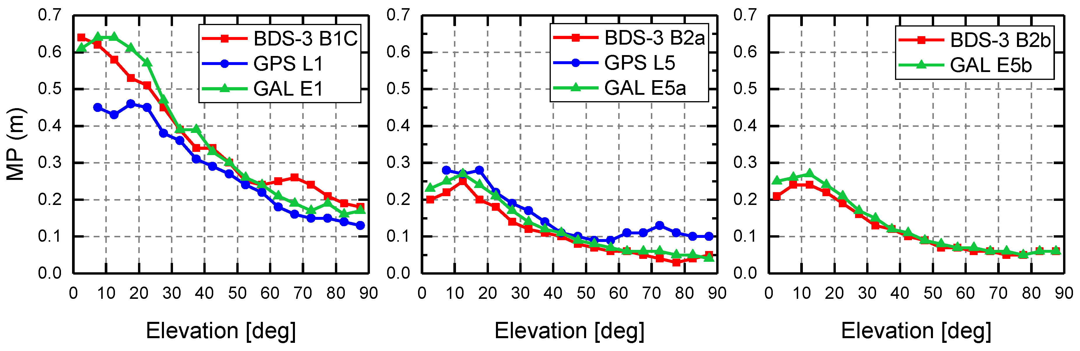
Figure 5 shows the RMS of receiver noise and multipath errors of BDS-3, GPS, and Galileo signals with overlapping frequencies, which are B1C/L1/E1, B2a/L5/E5a, and B2b/E5b. It can be seen that the differences of the RMS values are insignificant for each group of signals, and the pseudo-range errors of BDS-3 signals are comparable to those of GPS and Galileo. For B1C/L1/E1, the RMS values of the receiver noise and multipath errors are 0.1–0.2 m close to the zenith and increase to 0.4–0.6 m at low elevation angles, while for B2a/L5/E5a and B2b/E5b, the RMS values are less than 0.3 m over the entire elevation range, and less than 0.1 m at high elevation angles.
3.3. Satellite-Induced Code Bias
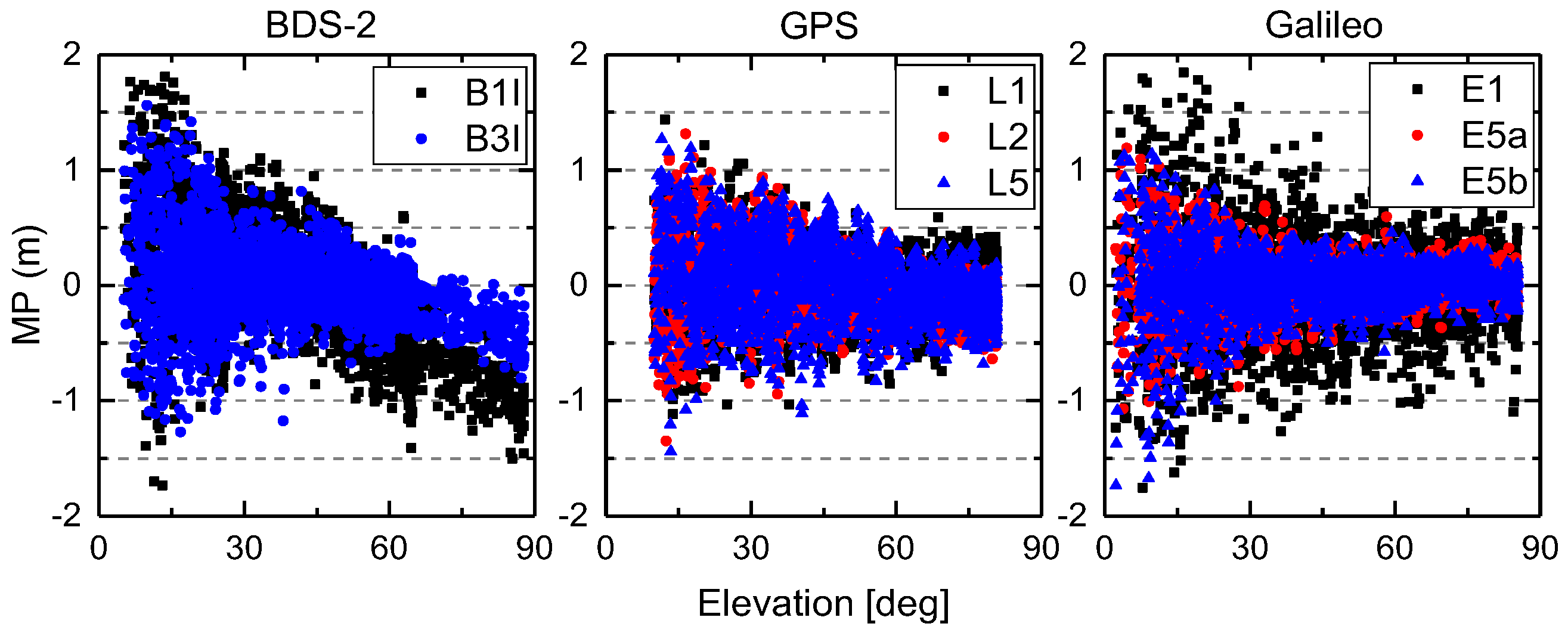
Satellite-induced code bias, which is absent from other GNSS satellites, has been identified to exist in BDS-2 code observations and reported in many studies [17,18,19]. In our experiment, it was further confirmed using observations from the iGMAS station, as shown in Figure 6. Since such an obvious bias was consistently observed with various receivers and antennas, it can likely be attributed to the transmitting satellites [20]. In addition, this satellite-induced code bias is frequency- and elevation-dependent, and can vary more than 1 m from horizon to zenith, which would severely affect BDS-2 precise applications involved with code observations [21,22,23]. Therefore, the question of whether this bias continues to exist in BDS-3 code observations deserves our attention.
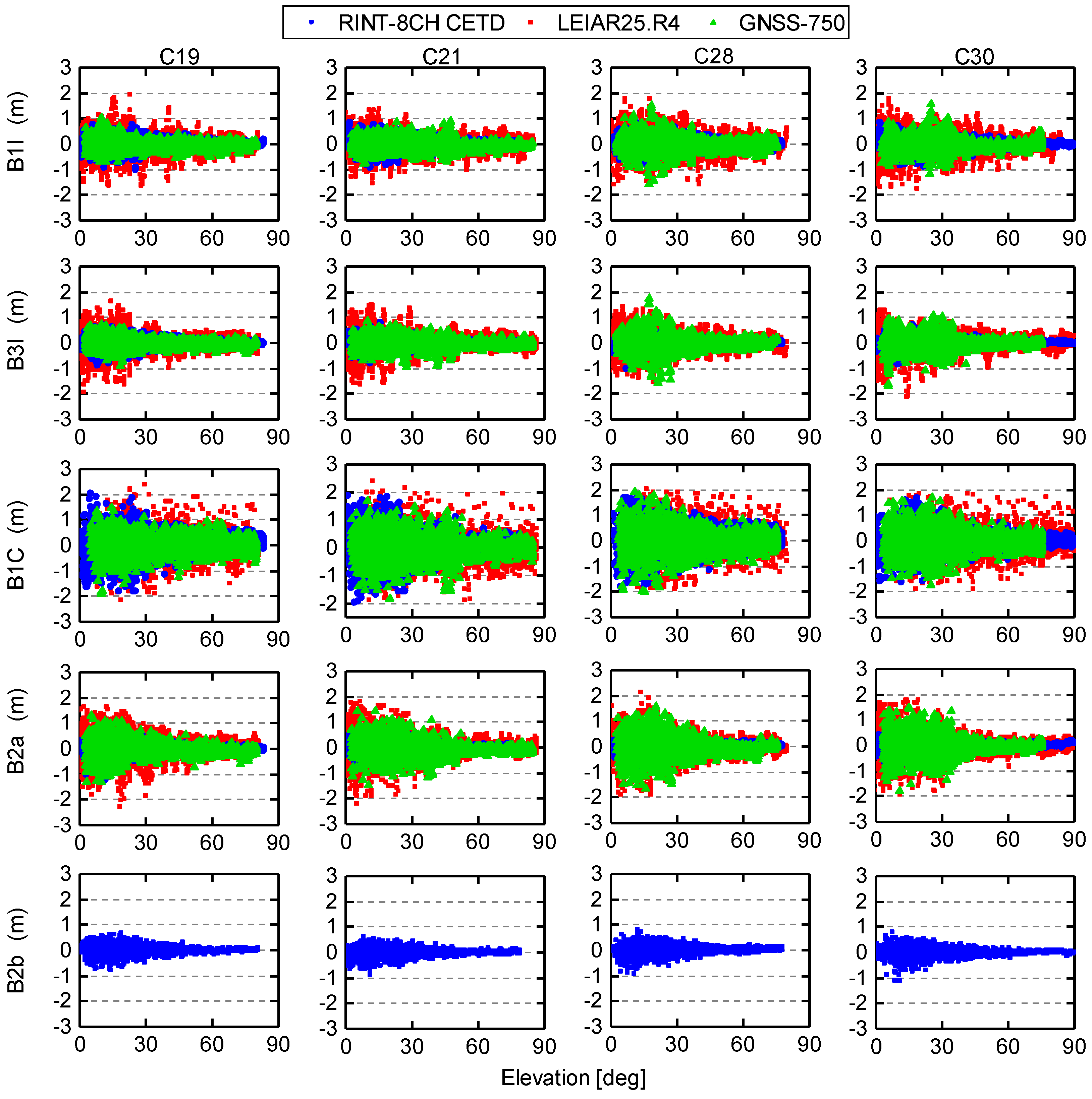
Figure 7 shows the MP series for five available BDS-3 signals observed from the station HMNS equipped with GNSS_GGR receiver and RINT-8CH CETD antenna, the station BJF1 with CETC-54-GMR-4016 receiver and LEIAR25.R4 LEIT antenna, and the station PETH with CETC-54-GMR-4011 receiver and GNSS-750 antenna, as listed in Table 3. The BDS-3 satellites used in this study can be divided into four groups (C19/C20, C21/C22, C27/C28, C29/C30) according to the launch status as shown in Table 1. We selected the results of one satellite from each group for illustration in Figure 7, and results of other BDS-3 satellites are similar. It should be noted that only the RINT-8CH CETD antenna is capable of receiving all five of the BDS-3 signals, and others cannot receive B2b signals in the iGMAS network (Table 3). From Figure 7, we can see that the MP values become more stable and gradually approach zero as the elevation angles increase. As was also seen in Figure 4, it is clear that the B1C signal is affected more seriously by multipath and noise for all selected satellites and stations due to a lower chip rate. Most notably, the satellite-induced elevation-dependent code biases of all the available BDS-3 signals observed by different GNSS receivers and antennas were dramatically reduced and considered to be inconsequential relative to those of BDS-2 in Figure 6.
3.4. Inter-Frequency Clock Bias
With the availability of three-frequency signals for GPS Block IIF satellites, inter-frequency clock bias (IFCB) was found, which was defined as the difference of the satellite clock offsets determined from two different ionosphere-free (IF) linear combinations of L1/L2 and L1/L5 carrier phase observations, and could most likely be attributed to inconsistency among frequency-dependent phase biases within a satellite [24,25]. According to previous studies, the IFCB between the BDS-2 B1/B2 and B1/B3 ionosphere-free satellite clocks showed a peak-to-peak amplitude of about 4 cm and, more noticeably, 10–40 cm for GPS Block IIF satellites [26,27]. In contrast, no apparent IFCB variations could be identified for the three signals of Galileo and QZSS satellites [28]. The presence of such IFCB makes it inappropriate to use one set of satellite clock products for data processing across all frequency bands, which complicates the implementation of triple-frequency PPP [29,30]. Thus, some approaches have been developed to estimate IFCBs [24,31]. The estimated IFCBs exhibit a time dependency and can be modeled. Li et al. [31] and Pan et al. [32] investigated the modeling of IFCBs for describing their characterization and predicting their values in advance.
As discussed in previous publications, the IFCB is directly observable from the triple-frequency carrier phase combination, which is the difference of two different carrier phase IF combinations, as follows:
where are carrier phase observations (in meters) on three distinct frequencies (with ). In addition to observing the IFCB variations, the triple-frequency carrier phase combination is usually used to assess carrier phase errors, since it is both geometry-free and ionosphere-free and reflects a weighted sum of the carrier phase multipath and noise on the respective frequencies after removing the constant ambiguity. Numerical values of the coefficients for several triple-frequency carrier phase combinations shown in this study are listed in Table 4. For BDS-2 satellites, the iGMAS stations can only receive double-frequency signals of B1I and B3I, and thus cannot form the combination. For BDS-3, some stations are capable of receiving five frequencies of signals, which provide more choices to form the triple-frequency carrier phase combination. In this study, (B1I, B3I, B2b) and (B1C, B2b, B2a) triple-frequency combinations of BDS-3 are chosen as typical examples for analysis.
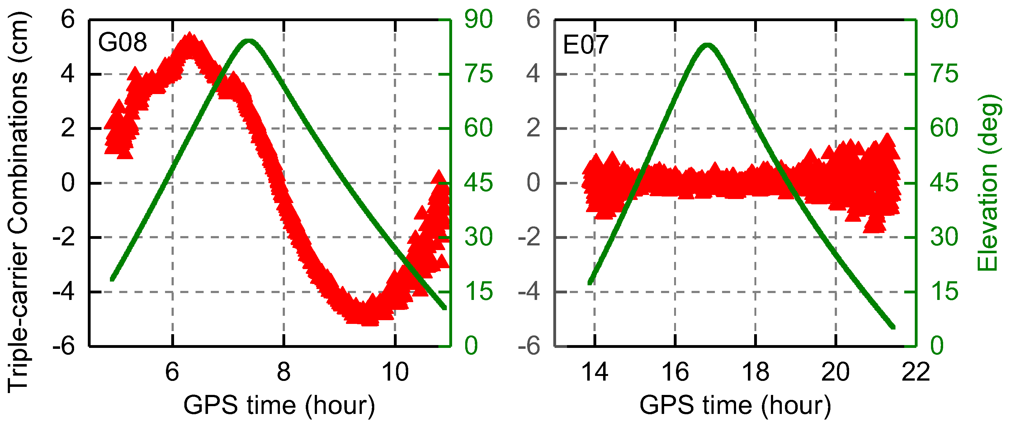
The triple-frequency carrier phase combinations for GPS Block IIF and Galileo satellites, which have been revealed in previous research, are further confirmed in our experiment, as shown in Figure 8, which plots the results of triple-frequency combinations for G08 and E07 satellites at station WHU1. As expected, obvious IFCB variations are recognized in the GPS Block IIF satellite and are confined to peak amplitudes of about 5 cm, while a good E1/E5b/E5a consistency and no significant bias variations can be seen in Galileo satellites.
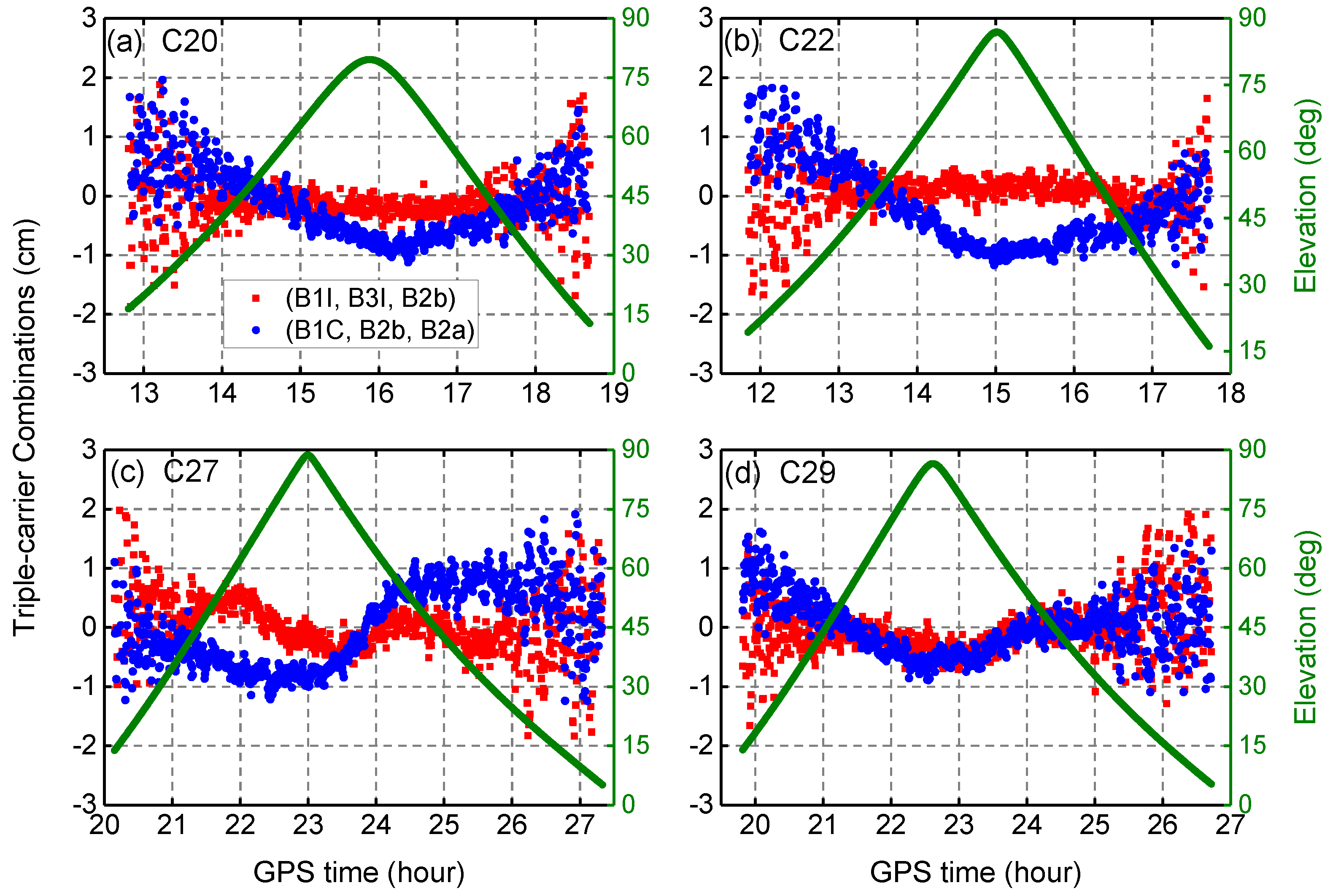
For BDS-3, the carrier phase observations on five frequencies from four selected satellites are used to form (B1I, B3I, B2b) and (B1C, B2b, B2a) triple-frequency combinations, as plotted in Figure 9. We can see that the time series of triple-frequency carrier phase combinations vary within ±2 cm for all the satellites. For C20 and C22 satellites manufactured by CAST, the (B1I, B3I, B2b) combination shows a good consistency and the series are dominated by the carrier phase multipath and noise with the dependence on elevation angles, while the (B1C, B2b, B2a) combination shows small IFCB variations with peak amplitudes of about 1 cm. For C27 and C29 satellites manufactured by CAS, the IFCB variations are observed in both (B1I, B3I, B2b) and (B1C, B2b, B2a) combinations and are generally confined to peak amplitudes of less than about 1 cm.
4. Discussion
The carrier-to-noise density ratio, pseudo-range noise and multipath, satellite-induced code bias and inter-frequency bias measured by the iGMAS stations for the different BDS-3 signals are characterized and compared with BDS-2, GPS, and Galileo. In addition to the old B1I and B3I signals inherited from the BDS-2 satellites, the BDS-3 satellites are capable of transmitting several new open service signals, namely B1C, B2a, and B2b. For the carrier-to-noise density ratio, the BDS-3 B1I signal is higher than that of BDS-2, and the B3I signals are at almost the same level. The new BDS-3 B2a/B2b signals have approximately similar signal strength to the GPS L5 and Galileo E5a/E5b signals, while BDS-3 B1C signals exhibit the lowest signal strength of all the analyzed signals, which is consistent with the results of analysis of BDS-3e satellites in Zhang et al. [5]. For the pseudo-range noise and multipath errors, the BDS-3 B1I/B3I signals show smaller errors compared with BDS-2, and B1C/B2a/B2b signals have no significant differences compared to GPS L1/L5 and Galileo E1/E5a/E5b signals.
Differently from other GNSS satellites, the BDS-2 code measurements are affected by satellite-induced biases larger than 1 m from horizon to zenith, which will inevitably affect the precise applications which involve the BDS-2 code measurements, such as single-frequency PPP [20] and PPP ambiguity resolution [21,22]. We use observations collected from different receivers/antennas to analyze the existence and magnitude of the satellite-induced code biases for the BDS-3 satellites. No obvious elevation-dependent and receiver-dependent code biases are identified for all of the available BDS-3 signals. Similar results have been found in previous experimental satellites [5,33]. This indicates that BDS-3 satellites have improved satellite internal hardware device design and navigation unit assembly to avoid the problem of satellite-induced code biases present in BDS-2, providing better performance.
For the IFCB variations, which have been identified to exist in BDS-2 and GPS Block IIF satellites [24,26], the small bias variations with peak amplitudes of about 1 cm can been found in BDS-3 triple-frequency carrier phase combinations. However, no apparent bias variations were observed for BDS-3e satellites in Zhang et al. [5] and Pan et al. [27]. Differences between the BDS-3 and BDS-3e satellites may be a cause of different results. In addition, it must be kept in mind that the triple-frequency carrier phase combinations show a comprehensive effect of the carrier phase noise, multipath, and the variations of the satellite phase hardware delay, namely IFCB. The results shown in Figure 9 might be affected by several factors, including the quality of the receiver and antenna, surroundings of station, and satellite internal hardware devices. The effect of such IFCB variations of BDS-3 satellites on multi-frequency data processing, e.g., triple-frequency PPP, need to be further investigated.
It should be noted that previous BDS-3e satellites, for the purpose of experiment validation, will not serve as a part of the BDS-3 satellite network. At present, the test task has been completed and these experimental satellites have been supplemented to the BDS-2 constellation. Although the signal characteristics of BDS-3e satellites have been analyzed in previous publications [5,13], it is still necessary to evaluate the performance of authentic BDS-3 satellites. The results of the satellite-induced biases are in line with the experimental satellites, and the results of IFCB variations are slightly different.
5. Conclusions
Following BDS-2 and BDS-3e satellites, China is rapidly launching its BDS-3 satellites. By June 2018, eight BDS-3 MEO satellites have been successfully launched into space. The transmitted signals of multi-GNSS satellites, including recently deployed BDS-3, have been tracked by a subset of the GNSS monitoring stations in the iGMAS network, enabling a meaningful characteristic analysis and performance assessment for various GNSS signals. The conclusions are summarized as follows:
- For the old B1I and B3I signals, BDS-3 shows a better performance compared with BDS-2. For the signals with overlapping frequencies of BDS-3, GPS, and Galileo, the observational quality of BDS-3 B2a/B2b signals is comparable to that of corresponding GPS and Galileo signals, while the BDS-3 B1C signal exhibits the lowest C/N0 values.
- Satellite-induced code biases are not obvious for all the available signals of BDS-3 satellites and may be negligible for high-precision applications.
- Inter-frequency clock bias still exists in BDS-3 signals, but the variations are small and generally confined to an amplitude of about 1 cm.
- The recently deployed BDS-3 satellites show similar signal tracking characteristics to the previous BDS-3e satellites.
The results mentioned above are expected to provide a useful understanding of performance, not only for the present BDS-3 satellites, but also for the iGMAS tracking network, hence potentially contributing to improvements to receivers and antennas. The performance of the BDS-3 system will be further verified and its long-term operation will be continuously analyzed via observation of the BDS-3 satellites. To facilitate further analysis, the GNSS receiver firmware in the iGMAS network should be upgraded to provide better tracking performance.
Author Contributions
R.F. conceived and designed the experiments; X.X. performed the data analysis and wrote the article; T.G. and G.W. reviewed and improved the paper; Q.Z. and J.L. supervised the experiments.
Funding
This research was funded by the National Natural Science Foundation of China (Grant Nos. 41631073, 41874038, 41674004, 41574030) and Key Laboratory of Geospace Environment and Geodesy, Ministry of Education, Wuhan University (Grant No. 413100041-17-02-10).
Acknowledgments
The contribution of data from iGMAS is greatly appreciated.
Conflicts of Interest
The authors declare no conflict of interest.
References
- Jiao, W.; Ding, Q.; Li, J.; Lu, X.; Feng, L.; Ma, J.; Chen, G. Monitoring and Assessment of GNSS Open Services. J. Navig. 2011, 64, S19–S29. [Google Scholar] [CrossRef]
- Cai, H.; Chen, G.; Jiao, W.; Chen, K.; Xu, T.; Wang, H. An Initial Analysis and Assessment on Final Products of iGMAS. In Proceedings of the China satellite navigation conference (CSNC) 2016, Changsha, China, 18–20 May 2016; pp. 515–527. [Google Scholar]
- Yang, Y.; Li, J.; Xu, J.; Tang, J.; Guo, H.; He, H. Contribution of the Compass satellite navigation system to global PNT users. Chin. Sci. Bull. 2011, 56, 2813–2819. [Google Scholar] [CrossRef] [Green Version]
- SCIO. China’s BeiDou Navigation Satellite System by the State Council Information Office of the People’s Republic of China (SCIO). 2016. Available online: http://www.beidou.gov.cn/xt/gfxz/201712/P020171221333863515306.pdf (accessed on 10 June 2017).
- Zhang, X.; Wu, M.; Liu, W.; Li, X.; Yu, S.; Lu, C.; Wickert, J. Initial assessment of the COMPASS/BeiDou-3: New-generation navigation signals. J. Geod. 2017, 91, 1225–1240. [Google Scholar] [CrossRef]
- Xie, X.; Geng, T.; Zhao, Q.; Liu, J.; Wang, B. Performance of BDS-3: Measurement Quality Analysis, Precise Orbit and Clock Determination. Sensors 2017, 17, 1233. [Google Scholar] [CrossRef] [PubMed]
- Wu, Z.; Zhou, S.; Hu, X.; Liu, L.; Shuai, T.; Xie, Y.; Tang, C.; Pan, J.; Zhu, L.; Chang, Z. Performance of the BDS3 experimental satellite passive hydrogen maser. GPS Solut. 2018, 22. [Google Scholar] [CrossRef]
- Xu, X.; Li, M.; Li, W.; Liu, J. Performance Analysis of Beidou-2/Beidou-3e Combined Solution with Emphasis on Precise Orbit Determination and Precise Point Positioning. Sensors 2018, 18, 135. [Google Scholar] [CrossRef] [PubMed]
- Tan, B.; Yuan, Y.; Wen, M.; Ning, Y.; Liu, X. Initial Results of the Precise Orbit Determination for the New-Generation BeiDou Satellites (BeiDou-3) Based on the iGMAS Network. ISPRS Int. J. Geo-Inf. 2016, 5, 196. [Google Scholar] [CrossRef]
- Zhang, X.; Li, X.; Lu, C.; Wu, M.; Pan, L. A comprehensive analysis of satellite-induced code bias for BDS-3 satellites and signals. Adv. Space Res. 2017. [Google Scholar] [CrossRef]
- Li, X.; Xie, W.; Huang, J.; Ma, T.; Zhang, X.; Yuan, Y. Estimation and analysis of differential code biases for BDS3/BDS2 using iGMAS and MGEX observations. J. Geod. 2018. [Google Scholar] [CrossRef]
- Xiao, W.; Liu, W.; Sun, G. Modernization milestone: BeiDou M2-S initial signal analysis. GPS Solut. 2015, 20, 125–133. [Google Scholar] [CrossRef]
- Yang, Y.; Xu, Y.; Li, J.; Yang, C. Progress and performance evaluation of BeiDou global navigation satellite system: Data analysis based on BDS-3 demonstration system. Sci. China Earth Sci. 2018, 61, 614–624. [Google Scholar] [CrossRef] [Green Version]
- Montenbruck, O.; Hauschild, A.; Hessels, U. Characterization of GPS/GIOVE sensor stations in the CONGO network. GPS Solut. 2010, 15, 193–205. [Google Scholar] [CrossRef]
- Kee, C. Calibration of multipath errors on GPS pseudorange measurements. In Proceedings of the ION GPS-1994, Salt Lake City, UT, USA, 20–23 September 1994; pp. 353–362. [Google Scholar]
- Estey, L.H.; Meertens, C.M. TEQC: The Multi-Purpose Toolkit for GPS/GLONASS Data. GPS Solut. 1999, 3, 42–49. [Google Scholar] [CrossRef]
- Montenbruck, O.; Hauschild, A.; Steigenberger, P.; Hugentobler, U.; Teunissen, P.; Nakamura, S. Initial assessment of the COMPASS/BeiDou-2 regional navigation satellite system. GPS Solut. 2012, 17, 211–222. [Google Scholar] [CrossRef]
- Shi, C.; Zhao, Q.; Hu, Z.; Liu, J. Precise relative positioning using real tracking data from COMPASS GEO and IGSO satellites. GPS Solut. 2012, 17, 103–119. [Google Scholar] [CrossRef]
- Pan, L.; Guo, F.; Ma, F. An Improved BDS Satellite-Induced Code Bias Correction Model Considering the Consistency of Multipath Combinations. Remote Sens. 2018, 10, 1189. [Google Scholar] [CrossRef]
- Wanninger, L.; Beer, S. BeiDou satellite-induced code pseudorange variations: Diagnosis and therapy. GPS Solut. 2014, 19, 639–648. [Google Scholar] [CrossRef]
- Lou, Y.; Gong, X.; Gu, S.; Zheng, F.; Feng, Y. Assessment of code bias variations of BDS triple-frequency signals and their impacts on ambiguity resolution for long baselines. GPS Solut. 2016, 21, 177–186. [Google Scholar] [CrossRef]
- Zhang, X.; He, X.; Liu, W. Characteristics of systematic errors in the BDS Hatch–Melbourne–Wübbena combination and its influence on wide-lane ambiguity resolution. GPS Solut. 2016, 21, 265–277. [Google Scholar] [CrossRef]
- Geng, T.; Xie, X.; Zhao, Q.; Liu, X.; Liu, J. Improving BDS integer ambiguity resolution using satellite-induced code bias correction for precise orbit determination. GPS Solut. 2017, 21, 1191–1201. [Google Scholar] [CrossRef] [Green Version]
- Montenbruck, O.; Hugentobler, U.; Dach, R.; Steigenberger, P.; Hauschild, A. Apparent clock variations of the Block IIF-1 (SVN62) GPS satellite. GPS Solut. 2011, 16, 303–313. [Google Scholar] [CrossRef]
- Li, H.; Zhou, X.; Wu, B. Fast estimation and analysis of the inter-frequency clock bias for Block IIF satellites. GPS Solut. 2013, 17, 347–355. [Google Scholar] [CrossRef]
- Zhao, Q.; Wang, G.; Liu, Z.; Hu, Z.; Dai, Z.; Liu, J. Analysis of BeiDou Satellite Measurements with Code Multipath and Geometry-Free Ionosphere-Free Combinations. Sensors 2016, 16, 123. [Google Scholar] [CrossRef] [PubMed]
- Pan, L.; Li, X.; Zhang, X.; Li, X.; Lu, C.; Zhao, Q.; Liu, J. Considering Inter-Frequency Clock Bias for BDS Triple-Frequency Precise Point Positioning. Remote Sens. 2017, 9, 734. [Google Scholar] [CrossRef]
- Hauschild, A.; Steigenberger, P.; Rodriguez-Solano, C. Signal, orbit and attitude analysis of Japan’s first QZSS satellite Michibiki. GPS Solut. 2011, 16, 127–133. [Google Scholar] [CrossRef]
- Pan, L.; Zhang, X.; Li, X.; Liu, J.; Li, X. Characteristics of inter-frequency clock bias for Block IIF satellites and its effect on triple-frequency GPS precise point positioning. GPS Solut. 2017, 21, 811–822. [Google Scholar] [CrossRef]
- Guo, J.; Geng, J. GPS satellite clock determination in case of inter-frequency clock biases for triple-frequency precise point positioning. J. Geod. 2017, 92, 1133–1142. [Google Scholar] [CrossRef]
- Li, H.; Li, B.; Xiao, G.; Wang, J.; Xu, T. Improved method for estimating the inter-frequency satellite clock bias of triple-frequency GPS. GPS Solut. 2015, 20, 751–760. [Google Scholar] [CrossRef]
- Pan, L.; Zhang, X.; Li, X.; Liu, J.; Guo, F.; Yuan, Y. GPS inter-frequency clock bias modeling and prediction for real-time precise point positioning. GPS Solut. 2018, 22, 76. [Google Scholar] [CrossRef]
- Zhou, R.; Hu, Z.; Zhao, Q.; Li, P.; Wang, W.; He, C.; Cai, C.; Pan, Z. Elevation-dependent pseudorange variation characteristics analysis for the new-generation BeiDou satellite navigation system. GPS Solut. 2018, 22. [Google Scholar] [CrossRef]
Figure 1.
Distribution of selected stations in the iGMAS network.

Figure 2.
Mean C/N0 values as a function of satellite elevation for all the available signals of GPS and Galileo (a–c) and BDS-2 and BDS-3 (d–f) at station CHU1 equipped with GNSS_GGR receiver (a,d); station CANB equipped with CETC-54-GMR-4011 receiver (b,e); and station ICUK equipped with CETC-54-GMR-4016 receiver (c,f), respectively.

Figure 3.
Mean C/N0 values as a function of elevation for the signals with overlapping frequencies of BDS-3, GPS, and Galileo at ABJA station. The signals include B1C/L1/E1 (a); B2a/L5/E5a (b); and B2b/E5b (c).
Figure 3.
Mean C/N0 values as a function of elevation for the signals with overlapping frequencies of BDS-3, GPS, and Galileo at ABJA station. The signals include B1C/L1/E1 (a); B2a/L5/E5a (b); and B2b/E5b (c).

Figure 4.
RMS of the noise and multipath errors as a function of satellite elevation for all the available signals of GPS and Galileo (a–c) and BDS-2 and BDS-3 (d–f) at station HMNS equipped with GNSS_GGR receiver (a,d); station PETH equipped with CETC-54-GMR-4011 receiver (b,e); and station LHA1 equipped with CETC-54-GMR-4016 receiver (c,f), respectively.

Figure 5.
RMS of the noise and multipath errors as a function of satellite elevation for the signals with overlapping frequencies of BDS-3, GPS, and Galileo at HMNS station. The signals include B1C/L1/E1 (a); B2a/L5/E5a (b); and B2b/E5b (c).
Figure 5.
RMS of the noise and multipath errors as a function of satellite elevation for the signals with overlapping frequencies of BDS-3, GPS, and Galileo at HMNS station. The signals include B1C/L1/E1 (a); B2a/L5/E5a (b); and B2b/E5b (c).

Figure 6.
Multipath (MP) series of tracked signals of BDS-2 (B1I/B3I), GPS (L1/L2/L5), and Galileo (E1/E5a/E5b) satellites as a function of satellite elevation at WUH1 station.
Figure 6.
Multipath (MP) series of tracked signals of BDS-2 (B1I/B3I), GPS (L1/L2/L5), and Galileo (E1/E5a/E5b) satellites as a function of satellite elevation at WUH1 station.

Figure 7.
MP combinations as a function of elevation for four BDS-3 satellites on five frequencies of signals observed at three iGMAS stations equipped with different antennas (RINT-8CH CETD/LEIAR25.R4 LEIT/GNSS-750) during DOY 150-152, 2018. The five rows from top to bottom represent five BDS-3 signals: B1I, B3I, B1C, B2a, and B2b; the four columns from left to right represent four selected BDS-3 satellites: C19, C21, C28, and C30.

Figure 8.
Variations of triple-frequency carrier phase combinations and elevation for G08 and E07 satellites at station WUH1 on 28 May 2018.
Figure 8.
Variations of triple-frequency carrier phase combinations and elevation for G08 and E07 satellites at station WUH1 on 28 May 2018.

Figure 9.
Variations of triple-frequency carrier phase combinations of (B1I, B3I, B2b) and (B1C, B2b, B2a) for C20, C22, C27, and C29 satellites during a pass at station HMNS.
Figure 9.
Variations of triple-frequency carrier phase combinations of (B1I, B3I, B2b) and (B1C, B2b, B2a) for C20, C22, C27, and C29 satellites during a pass at station HMNS.


Table 1.
Status of the BDS-3 satellites (June 2018).
| Satellite | SVN | Int. Sat. ID | Manuf. | PRN | Notes |
|---|---|---|---|---|---|
| BDS-3 MEO-1 | C201 | 2017-069A | CAST | C19 | Slot B-7; launched 5 Nov. 2017 PRN C19 used until 12 Jun. 2018 |
| BDS-3 MEO-2 | C202 | 2017-069B | CAST | C20 | Slot B-8; launched 5 Nov. 2017 |
| BDS-3 MEO-3 | C206 | 2018-018B | CAST | C21 | Slot B-5; launched 12 Feb. 2018 |
| BDS-3 MEO-4 | C205 | 2018-018A | CAST | C22 | Slot B-6; launched 12 Feb. 2018 |
| BDS-3 MEO-7 | C203 | 2018-003A | CAS | C27 | Slot A-4; launched 11 Jan. 2018 |
| BDS-3 MEO-8 | C204 | 2018-003B | CAS | C28 | Slot A-5; launched 11 Jan. 2018 |
| BDS-3 MEO-9 | C207 | 2018-029A | CAS | C29 | Slot A-2; launched 29 Mar. 2018 |
| BDS-3 MEO-10 | C208 | 2018-029B | CAS | C30 | Slot A-3; launched 29 Mar. 2018 |
Table 2.
Open service signals of BDS-2 and BDS-3.
| System | Signal | Frequency (MHz) | Wavelength (cm) | Chip Rate (Mcps) |
|---|---|---|---|---|
| BDS-2 | B1I | 1561.098 | 19.20 | 2.046 |
| B2I | 1207.140 | 24.83 | 2.046 | |
| B3I | 1268.520 | 23.63 | 10.23 | |
| BDS-3 | B1I | 1561.098 | 19.20 | 2.046 |
| B1C | 1575.420 | 19.03 | 1.023 | |
| B2a | 1176.450 | 25.48 | 10.23 | |
| B2b | 1207.140 | 24.83 | 10.23 | |
| B3I | 1268.520 | 23.63 | 10.23 |
Table 3.
Configuration of selected iGMAS stations.
| Abb. | Location | Receiver | Antenna | Tracked BDS-3 Signals |
|---|---|---|---|---|
| ABJA | Abuja | GNSS_GGR | RINT-8CH CETD | B1I, B3I, B1C, B2a, B2b |
| CHU1 | Changchun | GNSS_GGR | RINT-8CH CETD | B1I, B3I, B1C, B2a, B2b |
| GUA1 | Urumqi | GNSS_GGR | RINT-8CH CETD | B1I, B3I, B1C, B2a, B2b |
| HMNS | Hermanus | GNSS_GGR | RINT-8CH CETD | B1I, B3I, B1C, B2a, B2b |
| THAT | Tahiti | GNSS_GGR | RINT-8CH CETD | B1I, B3I, B1C, B2a, B2b |
| XIA1 | Xi’an | GNSS_GGR | RINT-8CH CETD | B1I, B3I, B1C, B2a, B2b |
| CANB | Canberra | CETC-54-GMR-4011 | GNSS-750 | B1I, B3I, B1C, B2a |
| DWIN | Darwin | CETC-54-GMR-4011 | GNSS-750 | B1I, B3I, B1C, B2a |
| PETH | Perth | CETC-54-GMR-4011 | GNSS-750 | B1I, B3I, B1C, B2a |
| ZHON | Antarctica | CETC-54 GMR-4011 | GNSS-750 | B1I, B3I, B1C, B2a |
| BJF1 | Beijing | CETC-54-GMR-4016 | LEIAR25.R4 LEIT | B1I, B3I, B1C, B2a |
| CLGY | Calgary | CETC-54-GMR-4016 | LEIAR25.R4 LEIT | B1I, B3I, B1C, B2a |
| WUH1 | Wuhan | CETC-54-GMR-4016 | LEIAR25.R4 LEIT | B1I, B3I, B1C, B2a |
| BRCH | Braunschweig | CETC-54-GMR-4016 | NOV750.R4 NOVS | B1I, B3I, B1C, B2a |
| LHA1 | Lhasa | CETC-54-GMR-4016 | NOV750.R4 NOVS | B1I, B3I, B1C, B2a |
| ICUK | London | CETC-54-GMR-4016 | NOV750.R4 NOVS | B1I, B3I, B1C, B2a |
| KNDY | Kandy | CETC-54-GMR-4016 | GNSS-750 | B1I, B3I, B1C, B2a |
Table 4.
Triple-frequency carrier phase combinations for analysis of carrier phase noise and multipath errors, as well as the inter-frequency clock bias (IFCB) variations.
Table 4.
Triple-frequency carrier phase combinations for analysis of carrier phase noise and multipath errors, as well as the inter-frequency clock bias (IFCB) variations.
| GNSS System | Signals | Combination |
|---|---|---|
| GPS | (L1, L2, L5) | +0.285 L1 − 1.546 L2 + 1.261 L5 |
| Galileo | (E1, E5b, E5a) | +0.161 E1 − 1.422 E5b + 1.261 E5a |
| BDS-3 | (B1I, B3I, B2b) | +0.457 B1I − 1.944 B3I + 1.487 B2b |
| (B1C, B2b, B2a) | +0.161 B1C − 1.422 B2b + 1.261 B2a |
© 2018 by the authors. Licensee MDPI, Basel, Switzerland. This article is an open access article distributed under the terms and conditions of the Creative Commons Attribution (CC BY) license (http://creativecommons.org/licenses/by/4.0/).
Share and Cite
MDPI and ACS Style
Xie, X.; Fang, R.; Geng, T.; Wang, G.; Zhao, Q.; Liu, J. Characterization of GNSS Signals Tracked by the iGMAS Network Considering Recent BDS-3 Satellites. Remote Sens. 2018, 10, 1736. https://0-doi-org.brum.beds.ac.uk/10.3390/rs10111736
AMA Style
Xie X, Fang R, Geng T, Wang G, Zhao Q, Liu J. Characterization of GNSS Signals Tracked by the iGMAS Network Considering Recent BDS-3 Satellites. Remote Sensing. 2018; 10(11):1736. https://0-doi-org.brum.beds.ac.uk/10.3390/rs10111736
Chicago/Turabian StyleXie, Xin, Rongxin Fang, Tao Geng, Guangxing Wang, Qile Zhao, and Jingnan Liu. 2018. "Characterization of GNSS Signals Tracked by the iGMAS Network Considering Recent BDS-3 Satellites" Remote Sensing 10, no. 11: 1736. https://0-doi-org.brum.beds.ac.uk/10.3390/rs10111736
Note that from the first issue of 2016, this journal uses article numbers instead of page numbers. See further details here.