Multi-Instance Inertial Navigation System for Radar Terrain Imaging


Faculty of Electronics, Military University of Technology, ul. gen. S. Kaliskiego 2, 00-908 Warsaw, Poland
*
Author to whom correspondence should be addressed.
Remote Sens. 2020, 12(21), 3639; https://0-doi-org.brum.beds.ac.uk/10.3390/rs12213639
Submission received: 24 September 2020
/
Revised: 30 October 2020
/
Accepted: 3 November 2020
/
Published: 6 November 2020
(This article belongs to the Special Issue Multi-Sensor Systems and Data Fusion in Remote Sensing)
Abstract
:Navigation systems used for the motion correction (MOCO) of radar terrain images have several limitations, including the maximum duration of the measurement session, the time duration of the synthetic aperture, and only focusing on minimizing long-term positioning errors of the radar host. To overcome these limitations, a novel, multi-instance inertial navigation system (MINS) has been proposed by the authors. In this approach, the classic inertial navigation system (INS), which works from the beginning to the end of the measurement session, was replaced by short INS instances. The initialization of each INS instance is performed using an INS/GPS system and is triggered by exceeding the positioning error of the currently operating instance. According to this procedure, both INS instances operate simultaneously. The parallel work of the instances is performed until the image line can be calculated using navigation data originating only from the new instance. The described mechanism aims to perform instance switching in a manner that does not disturb the initial phases of echo signals processed in a single aperture. The obtained results indicate that the proposed method improves the imaging quality compared to the methods using the classic INS or the INS/GPS system.
1. Introduction
Most navigation systems are aimed at minimizing slow-varying position and velocity errors of the object. These methods aim to keep the errors at a low level for as long as possible. However, there are certain applications that impose specific demands on navigation systems, e.g., synthetic aperture radar (SAR) terrain imagery.
Synthetic aperture radars allow for high-resolution terrain imaging with similar quality to optical methods. In contrast, however, this technique is independent of weather and lighting conditions. Currently, unmanned aerial vehicles (UAV) are commonly used as carriers of SAR systems. In side-looking aerial radar (SLAR), the direction of flight is called azimuth while the direction of observation is called range [1].
The advantages of SAR systems are accompanied by high requirements and limitations. To get focused and geometrically correct images, the UAV must move in a strictly defined manner, most often with uniform rectilinear motion, which ensures proper conditions for receiving and processing echo signals [2,3,4,5,6,7,8,9]. However, in real-world scenarios it is impossible to fulfill these requirements.
In [10], Fornaro distinguished three types of SAR-carrier trajectories: nominal, real, and measured. Due to measurement errors, the measured trajectory does not coincide with the real one. The discrepancy between the real and the nominal trajectories result from atmospheric disturbances and autopilot controls [3]. According to [6,11], the unfavorable effects of the atmosphere on the UAV lead to the range (radar to object) distance instabilities, nonuniform UAV motion in the azimuth direction, and changes in the UAV’s attitude. Groundspeed variations can be compensated by adjusting the radar pulse repetition frequency (PRF) so the distance traveled by a UAV in one pulse period is constant [12]. The second method of groundspeed instability compensation consists in resampling the received echo signals [2,3]. The UAV attitude variation can be compensated by the radar antenna stabilization system [13]. As a result, the flightpath curvature has the most negative impact on the quality of radar images. According to Kirk [4] and Fornaro [3], UAV movement instabilities can be divided into low- and high-frequency errors. Low-frequency errors (with a period longer than a duration of the synthetic aperture) lead to a shift in the center frequency of the echo signal, which results in geometric distortions of the image. High-frequency errors (with a period shorter than the synthetic aperture) increase the amplitude of the side lobes, which blurs the image. Therefore, the compensation of these errors has the greatest impact on the quality of radar images [9]. As a result, in SAR systems it is necessary to compensate the influence of UAV motion instabilities on the received echo signal phase history. These procedures are called motion compensation (MOCO) [14]. MOCO algorithms can be divided into procedures using navigation equipment, as well as procedures based on the analysis of the echo signal (autofocus) [10,14].
In navigation procedures, the echo signal phase correction is performed based on the measured and calculated discrepancy between the nominal and actual trajectories. However, the navigation system is a source of additional errors, which could decrease the quality of SAR images. The analysis of the inertial measurement unit (IMU) and INS errors in the imaging process is presented in [15]. The paper [16] presents the SAR MOCO procedure using INS navigation corrections, which suggest that in the case of the limited duration of the measurement session (approx. 30 s), it is possible to significantly improve the image quality.
In the case of the navigation systems dedicated to cooperation with SAR radars, it is necessary to consider their accuracy in the short and long term. The INS system ensures high short-term accuracy, but in the long-term perspective an increase of the positioning errors is the main disadvantage of the inertial navigation [17]. This drawback can be compensated for using additional sensors (e.g., Doppler radar, GPS receiver), ensuring a high long-term accuracy [18]. The disadvantage of this approach, however, is high-frequency measurement errors, which transfer to the MOCO procedure (through a data fusion algorithm), causing errors in the initial phase of the echo signals.
In the article [19], Fuxiang and Zheng noticed that navigation systems proposed in the MOCO literature, and in particular the methods of INS and GPS data integration, are predominantly focused on reducing the long-term errors, which makes them more suitable for navigating than for SAR MOCO. For example, in [20] Gong and Fang presented the navigation system used in MOCO, consisting of INS and GPS with real time kinematic (RTK). They presented four strategies for integrating the measurement data: a Kalman filter, an extended Kalman filter (EKF), a combination of the unscented Kalman filter (UKF) with an EKF, and a model predictive filter (MPF) with an EKF. The authors focused on long-term error minimalization and did not consider the impact of the short-term errors on the radar images. Focusing on the navigation system, and disregarding its influence on the SAR subsystem, is a common practice in the literature [19,21,22].
In the work [19], Fuxiang and Zheng presented a proposal to solve the high-frequency navigation system errors caused by GPS. According to the authors, the period of the Kalman filter correction phase (the period of GPS data used in the filter) should be longer than the duration of a synthetic aperture. In such a system, the INS errors grow during the synthetic aperture, which, however, is much less disadvantageous than random changes introduced by the GPS. Unfortunately, this limits the duration of the synthetic aperture, which may be especially problematic in the case of UAVs moving with low speeds in the azimuthal direction. A short synthetic aperture decreases the spatial resolution of the radar image.
According to Kennedy’s work [15], the INS used in a MOCO algorithm should not be reinitialized during the synthetic aperture. A proposed solution consists of the main INS (aircraft navigation system) and the auxiliary INS (IMU mounted on the radar antenna). A correction of the auxiliary INS (reinitialization) is performed after the synthesis of the aperture has been completed. This method is therefore analogous to that proposed by Fuxiang and Zheng [18]; they differ only in the source of the correction information (main INS or GPS receiver).
In [21], Fang and Gong presented a navigation system divided into two INS blocks using a common IMU. Errors of the main INS are estimated by a Predictive Iterated Kalman Filter (PIKF) by comparing results from the INS and GPS. As proposed by the authors, the main INS is only used during the approach to the radar scanning area. At the start of the measurement session, the output from the main INS is used to initialize the secondary INS (not corrected by the GPS), whose output is used in the SAR MOCO algorithm. The proposed mechanism has two goals. The first one is to reduce the operating time (and errors) of the secondary INS. The second goal is to reduce the influence of the GPS errors on the MOCO by isolating two INS blocks. The authors emphasize that the radar measurement session should last no longer than 15 s to keep INS errors at an acceptable level.
The second group of MOCO methods, called autofocus, consists in the analysis of the echo signals received by the radar sensor [14,23,24,25,26,27,28,29,30,31,32,33]. A great variety of autofocus methods exists due to their individual limitations, e.g., the Phase Gradient Autofocus (PGA) needs the presence of highly reflective objects in the imaged area [24], while in the Map-Drift method the area should be diversified (presence of edges, shadows, etc.) [32]. A majority of autofocus methods are iterative, which extends the time needed to obtain a result (image) [23]. For comparison, in the navigational MOCO procedures the image synthesis is performed once, and the corrections are computed independently in a dedicated subsystem. As a result, in navigational MOCO it is possible to reduce the computational effort (no iterations) and time consumption.
In summary, there are currently several navigational MOCO procedures using data from INS or INS/GPS systems. However, in many cases the navigation system is not optimized for the MOCO algorithm—these methods focus on the long-term accuracy of the system, ignoring the adverse impact of fast-changing errors contributed by the GPS receiver. In papers dealing with this problem, the authors have proposed methods limiting the duration of the synthetic aperture (shorter than the GPS update period) or limiting the duration of the measurement session (INS-only systems).
Based on this analysis, the authors propose a multi-instance INS (MINS) system, combining the advantages of the classic INS and INS/GPS systems. This paper is related to the works presented in [16,34,35,36]. An application of pure inertial navigation for SAR MOCO is presented in [16] and using INS/GPS for MOCO is described in [34]. A method of calculating position deviations from a theoretical, nominally rectilinear trajectory for a UAV-based SAR is explained in [36]. The MOCO method presented in this paper, however, is new and has not been presented before, both by the authors of this paper nor by other authors. The results presented in the further parts of this paper, based on real measurements obtained during UAV flights, show that the proposed MINS system is in many aspects superior with respect to the INS and the INS/GPS systems used for SAR MOCO applications.
The layout of the further parts of this paper is as follows: the idea of a multi-instance inertial navigation system is explained in Section 2, selected results of testing the algorithm with the use of real navigation data are presented in Section 3, whereas in Section 4 the influence of the MINS-based MOCO on SAR images is compared with the results obtained with other MOCO methods. Conclusions are provided in Section 5.
2. Materials and Methods
The proposed MOCO method, using the MINS system, is based on a combination of INS and INS/GPS systems described in [16,34,36]. The results presented in the mentioned papers show that each proposed solution improves the quality of SAR images, but in both cases the improvement is only partial and complementary. The INS system improves the image contrast (IC), entropy (E), spatial resolution (SR), peak to sidelobe ratio (PSLR), and integrated sidelobe ratio (ISLR), while the INS/GPS system better reduces the image geometric distortions.
The purpose of INS instances proposed in MINS is to keep INS errors limited in such a way that the corrections calculated by a navigation correction algorithm (NCA) [36] do not disturb the initial phases of radar echo signals in a single synthetic aperture. Therefore, in the proposed system, the INS error corrections are not performed during an aperture synthesis. During any single synthetic aperture, only the uncorrected INS system is used as a data source for an NCA, and a periodic INS correction, using the INS/GPS system, is conducted in a special manner that takes into account the specificity of the aperture synthesis algorithm.
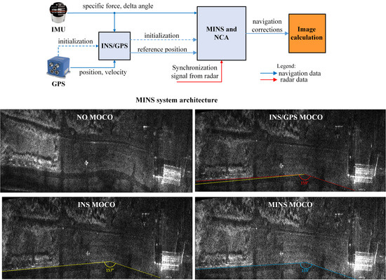
The proposed method assumes a parallel work of the MINS and INS/GPS systems. A diagram illustrating the concept of such a system is shown in Figure 1.
The INS/GPS subsystem [34] determines the UAV’s position, velocity, and attitude. Its output is then used to initialize the i-th INS instance, , in the MINS system. The integrated system also provides the position reference used to calculate MINS errors. Data obtained from the MINS are then used by the NCA to determine the navigation corrections for the SAR system. The INS/GPS system is initialized at the system launch and works until its power is off.
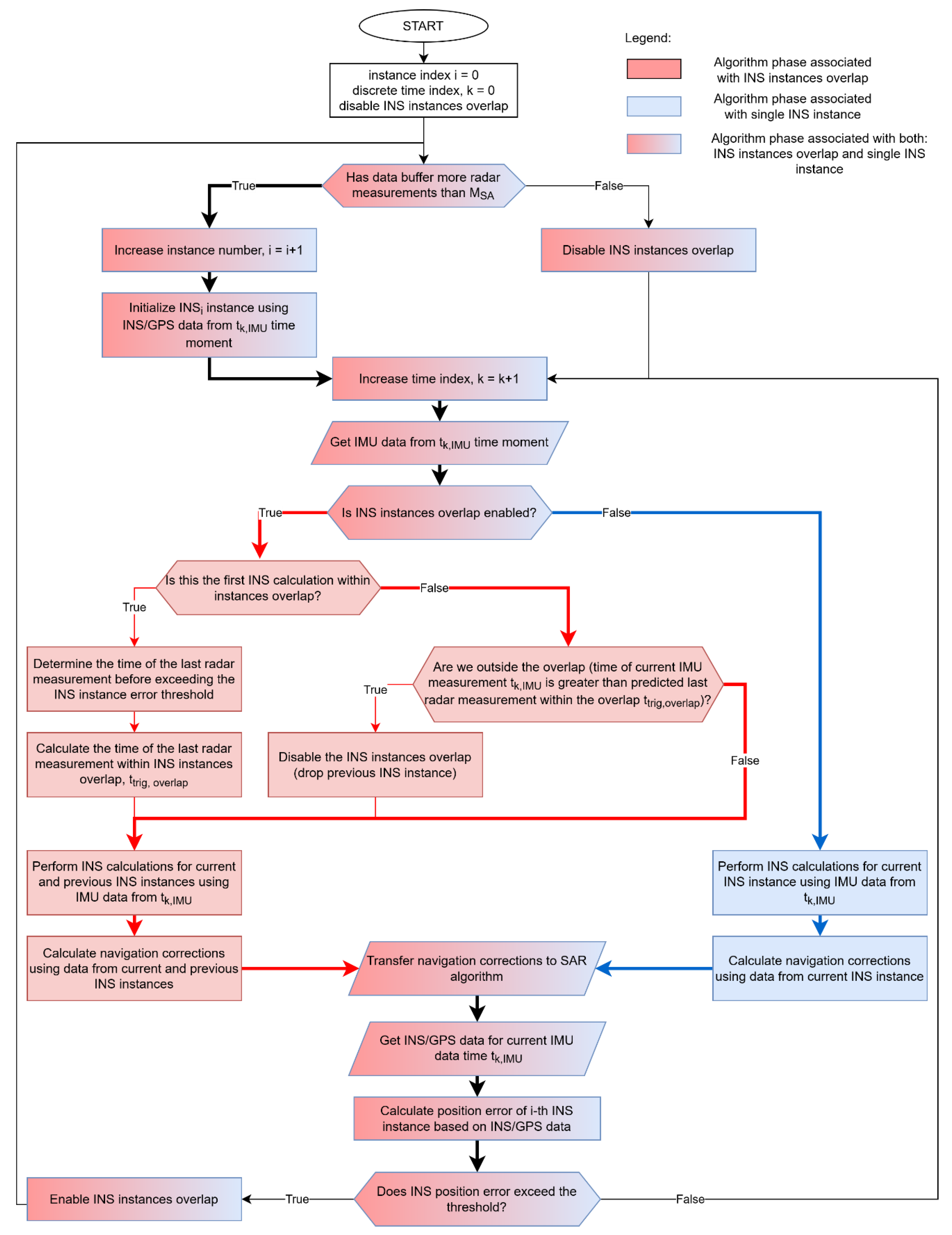
The detailed algorithm of MINS is presented in Figure 2. It has two main branches presented in Figure 2 using red and blue colored boxes and lines. The red branch is related to the overlapping INS instances, i.e., a situation when two INS instances work in parallel. The blue branch is executed when an INS overlap is finished or impossible to create and is related to a situation when only a single INS instance is working.
The SAR system synthesizes the image line for the central measurement within the synthetic aperture of length , where is the number of soundings that make up the synthetic aperture. Therefore, the IMU and radar data have to be buffered and the navigation algorithm’s output is delayed by the duration of the aperture (usually less than 1 s). The switching of INS instances can be performed if the buffer contains enough IMU data to calculate navigation corrections for the new synthetic aperture. During the MINS system operation, the IMU measurements are used both by the INS/GPS and an i–th instance . Both systems calculate the position and velocity of the UAV’s center of gravity (the origin of the body frame, b-frame). The results from the are then compared with the current INS/GPS estimates.
When exceeds a position error threshold and data buffer contains enough IMU data, the instance number i is increased and the next INS instance is started (the red part of the algorithm becomes active). If there is not enough data in the buffer (e.g., due to the end of the measurement session), then no new INS instance is created and the current instance runs until all the buffered data have been processed. A new INS instance is initialized using the INS/GPS data determined for the moment when the position error threshold was exceeded. The position error, denoted as , is a norm of the vector describing the position difference of the b-frame origin expressed in the n-frame navigation system (North East Down, NED), determined by the i-th INS instance () and the INS/GPS system ():
where , , are position coordinates expressed in the n-frame. After exceeding the position error threshold , i.e., when:
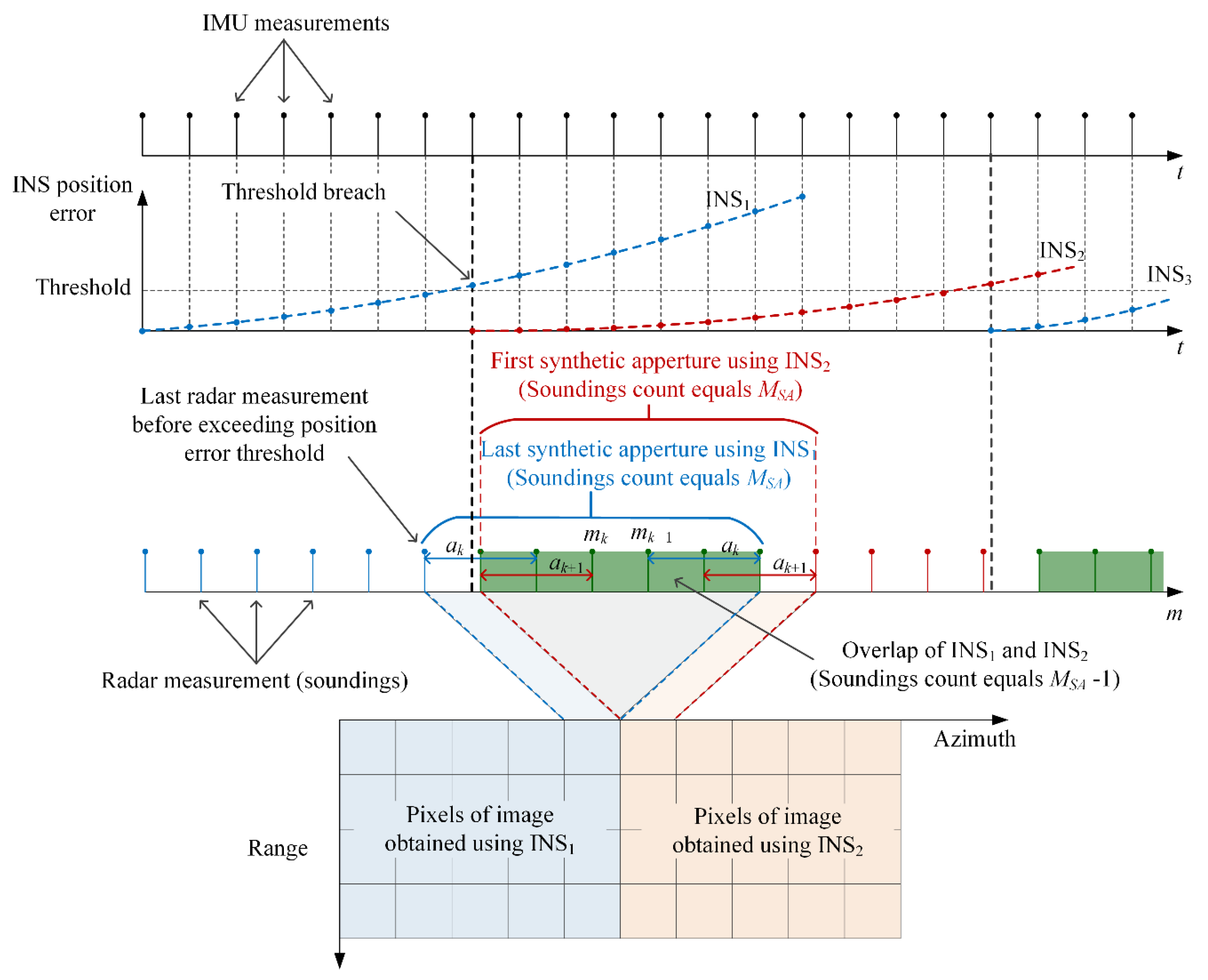
the instances and run in parallel, as shown in Figure 3. The purpose of the simultaneous operation of both instances is to enable their switching in a way that does not occur within a single synthetic aperture, which could lead to an abrupt change of the calculated position. Switching the INS instance (the source for the NCA) is performed after the current aperture is synthesized and before moving to the next aperture, which ensures smooth navigation data used in each of them.
At the end of the overlap, the set of navigational corrections determined on the basis of the new instance is sufficiently large to allow for an aperture synthesis. As a result, after instance switching, the pixels that make up a given line of the image are created using the data, while the previous line was created using the instance. The length of the overlap can be expressed in terms of the number of radar soundings. The parallel work of instances begins at the time of the first IMU measurement after exceeding the INS error threshold, continues through radar soundings, and ends when the first IMU measurement occurs after processing the given number of soundings. In the radar system used in the further described experiments, is an odd number:
where is a rounded down number of soundings making up half of the synthetic aperture.
The navigational corrections are calculated using results of the INS instance. During the overlap, a pair of corrections are determined using and . The image synthesis algorithm, thanks to the knowledge about the length of the synthetic aperture shared with MINS, can detect the end of the correction data set and switch to the next source—the next INS instance.
In the presented algorithm, the INS instance initialization procedure can be interpreted as a form of INS error correction; however, the INS/GPS data are not used to correct the current INS instance (the errors of which continue to increase) but to initialize a new one. The initial INS errors correspond to small errors of the INS/GPS system. Thus, the proposed method combines the advantages of the INS and the INS/GPS systems. Thanks to the initialization of the instances, it is possible to keep INS errors at a low level, depending on the established error threshold, and at the same time the NCA uses the uncorrected INS results. According to the conclusions presented in [16] and [34], this should have a positive impact on the quality of the radar terrain images.
3. Results
The MINS system was tested using measurement data from the WATSAR radar system [37]. Before starting the navigation calculations, it was necessary to determine the value of . If the value is too high, it leads to a shift between two image parts generated using INS data from the successive instances. The threshold value should also not be too low, as it would result in a short duration of INS instances, potentially shorter than the duration of the synthetic aperture, which in the WATSAR system was about 0.606 s. Taking into account the class of IMU used in the WASTAR system, the threshold was experimentally established and equaled 0.25 m.
After the threshold is exceeded, the errors of the instance still increase, but the time duration of this instance is limited to the time of the overlap. In a test flight (named here flight no 1), six INS instance switches were performed. Table 1 summarizes the duration of individual instances and the final values of position errors in relation to the INS/GPS trajectory.
The time duration of instances is varied and ranges from 2.053 to 6.966 s. The reasons for this variation are initialization errors of INS instances and INS/GPS errors—GPS errors cause small step changes in . Figure 4 shows the position error of the first instance of flight no 1.
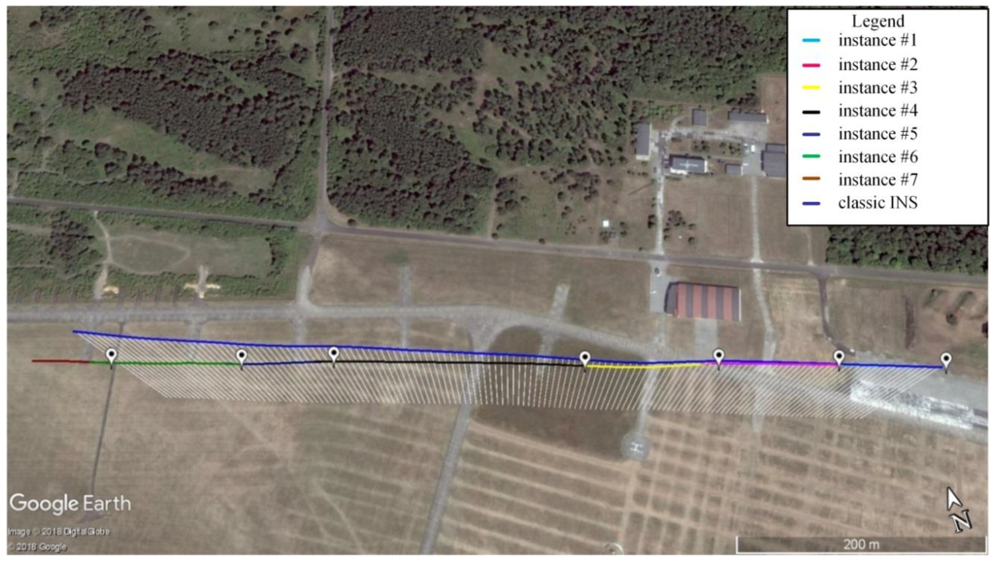
A visualization of the UAV flight trajectory determined by the MINS system for flight no 1 is shown in Figure 5. The white markers indicate locations where the instances were initialized.
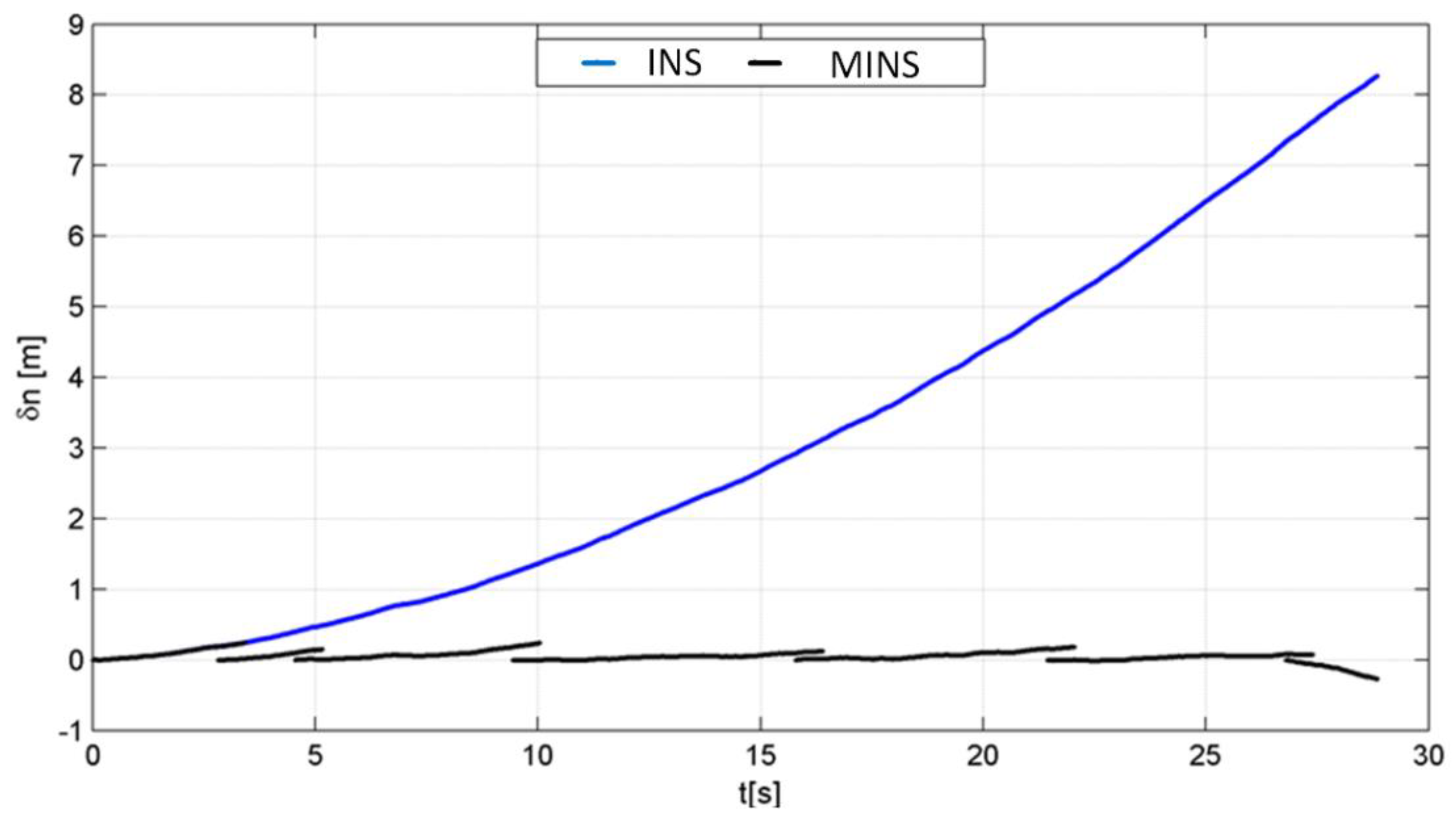
A visual comparison of the position errors of the classic INS and the proposed MINS, determined with respect to the INS/GPS data, is shown in Figure 6, while Figure 7 and Figure 8 show analogous results for the velocity and the velocity errors.
Thanks to the INS instance switching mechanism, the error in determining the navigation elements is kept at a low level, similar to the INS/GPS system, and the value of maximum error is related to the adopted threshold, which triggers a new instance. In the MINS system, the INS instances are initialized using INS/GPS data, thus the MINS trajectories originate on the INS/GPS trajectory. A random character of data presented in Figure 8 is caused by the error calculation mechanism, where from “smooth” INS data the “noisy” INS/GPS results were subtracted.
4. Discussion
MINS-based MOCO results were compared with those obtained using other MOCO methods: INS [16] and INS/GPS [34]. Based on the corrections, the radar terrain images of the region presented in Figure 10 were calculated. The radar terrain image obtained without MOCO correction, for flight no 1, is shown in Figure 11. Figure 12 presents an image obtained using INS-based MOCO, Figure 13 shows an image calculated using INS/GPS-based MOCO, whereas Figure 14 shows an image obtained using the proposed MINS system.
The total flight duration along the scanned area was approximately 29 s and was limited by the Visual Line of Sight (VLOS) UAV rules. Along the azimuth direction, the scanned swath had a length of 680 m. During imaging, the UAV moved along a semilinear trajectory. Its rectilinear shape was imposed by the radar aperture synthesis algorithm implemented in our system and described in [38]. In general, the applied SAR procedure allows for a nonrectilinear UAV motion as its displacements from an assumed linear trajectory are compensated using navigation corrections and the MOCO procedure. However, during large maneuvers (e.g., rapid turns) the spatial resolution of the image can be degraded. Therefore, our system is typically used for SAR imaging during flights along almost rectilinear trajectories. In order to present data representative for a normal operational use of the system, only straight flight trajectories were considered.
The geometric distortions of images were determined by measuring the angle between northern edges of the taxiway, whose true value is 159°. In Figure 12 (INS-based MOCO), the edge is marked in yellow, and the measured angle is 157°. The two-degree discrepancy is related to the slowly growing INS positioning errors with a final value of 11.7 m. In the case of INS/GPS-based MOCO, the taxiway edge is marked in red (Figure 13), while the measured angle is concise with the true one. In this image, the geometric distortions are reduced thanks to the INS error correction with the GPS receiver and the Kalman filter. In addition, in the case of the proposed MINS system, the taxiway angle has a proper value. In this system, the positioning error is kept low by the instance switching mechanism.
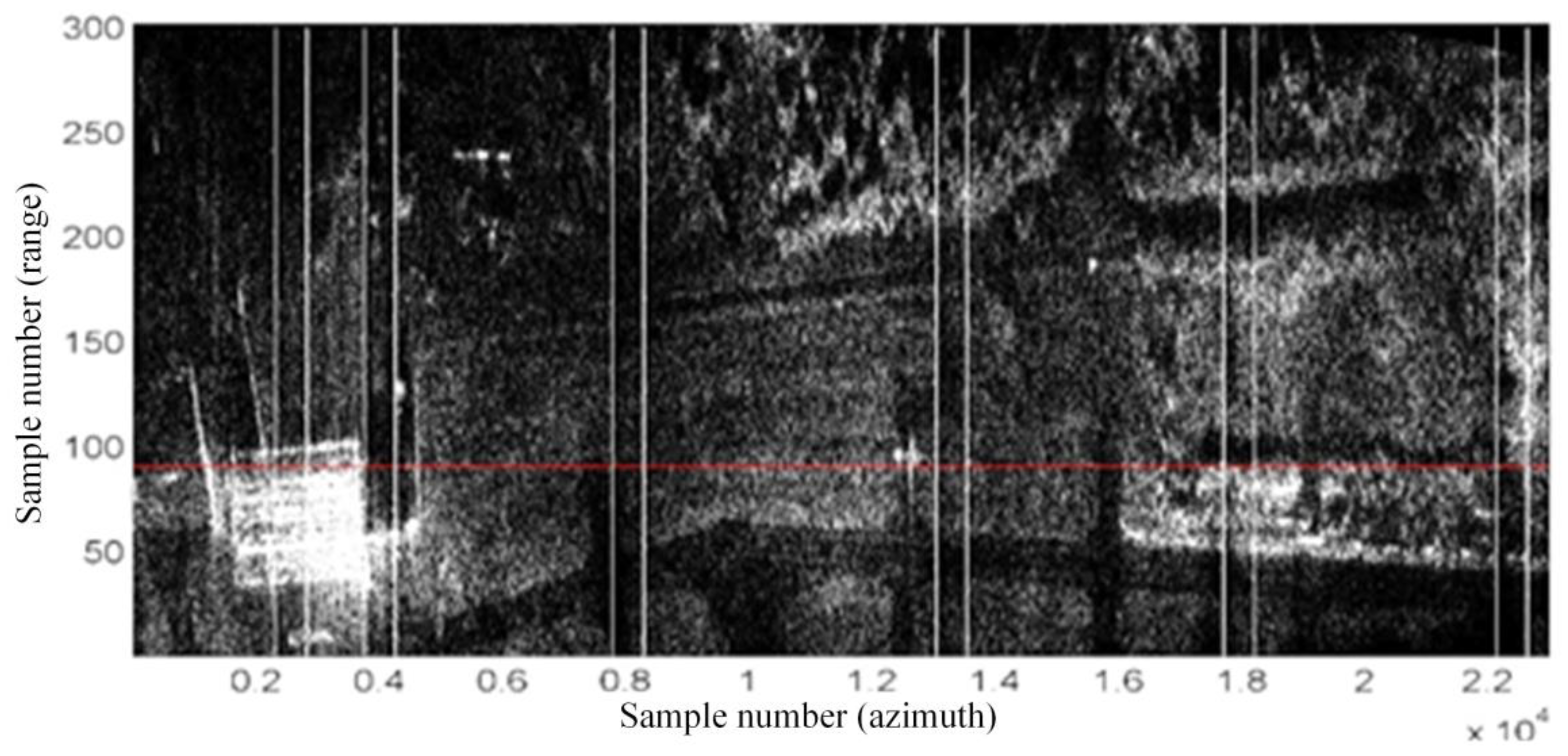
Vertical white lines, presented in Figure 15, mark the ranges of radar measurements with INS overlaps. As can be seen, these overlaps do not deteriorate the image quality or geometric conciseness of the image.
Radar terrain images obtained using the three considered MOCO methods (INS, INS/GPS, and MINS) were also compared using quality indicators such as image contrast (IC), entropy (E), spatial resolution (SR), PSLR, and ISLR [25,29,39,40,41]. The results are presented in Table 2.
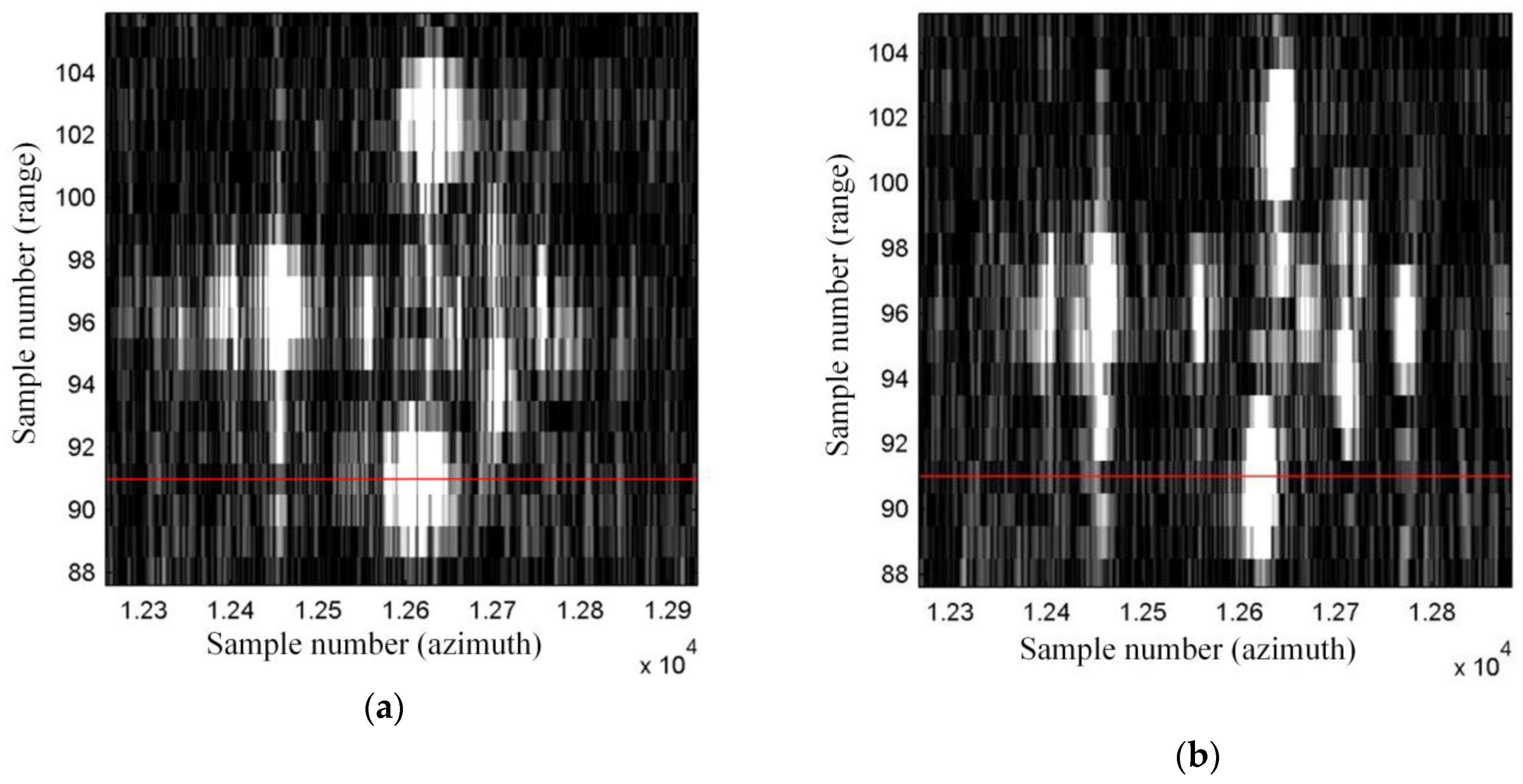
The image obtained using MINS-based MOCO has a better (higher) contrast than the image calculated without the navigation correction (IC increases from 4.06 to 8.01). This result is also better than the contrast of the INS/GPS-based image (IC = 7.56) and comparable to the contrast of the INS-based image (IC = 8.32). The improvement is also visible in the image entropy. Due to the usage of MINS-based MOCO, a reduction (improvement) of entropy was achieved in relation to the image without MOCO (E decreases from 14.43 to 13.84). The obtained result is also better than the entropy of the INS/GPS-based image (E = 13.94) and similar to the result obtained with a traditional INS (E = 13.83). The SR, PSRL, and ISLR parameters are determined based on point-like objects in the images. For this purpose, during preparations to the experiment a set of corner reflectors was placed in the central part of the imaged area and arranged in the shape of an arrow. In Figure 15 and Figure 16, the horizontal red line marks the image line running through a corner reflector located in the lower arm of the arrow, for which SR, PSLR, and ISLR were calculated. The normalized amplitude of image pixels measured along this line is presented in Figure 17.
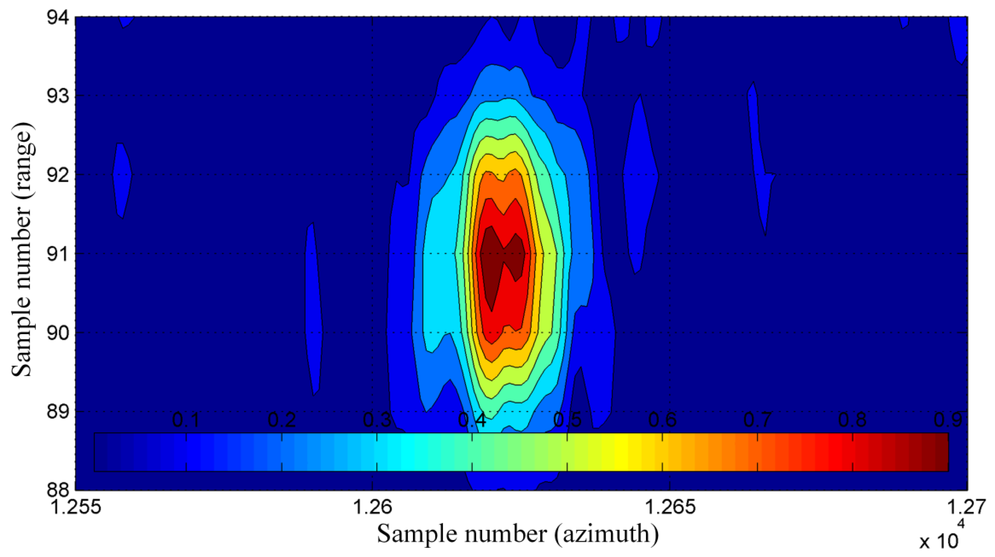
Compared to the image obtained using the INS/GPS system, in the case of the MINS-based image the amplitude of sidelobes is lower (which is an advantage), while the main lobe is apparently wider. As a result, the SR of the MINS-based image (SR = 0.278 m) is slightly better than in the INS-based image (SR = 0.304) and theoretically worse than the result obtained with INS/GPS-based MOCO (SR = 0.119). In the case of the INS/GPS method, however, it should be noted that high-level sidelobes deteriorate the practical resolution, which can be seen in Figure 16. Visualization of the normalized amplitude in 2D is shown in Figure 18 and Figure 19.
MINS-based MOCO allowed the best (lowest) values of PSLR and ISLR to be obtained among three analyzed navigation systems (PSLR = −8.57 dB, ISLR = −10.68 dB). The improvement with respect to the INS/GPS-based image (PSLR = 2.99 dB, ISLR = −1.52 dB) results from the smoothness of the navigation data calculated by the MINS system. The improvement with respect to the INS-based image (PSLR = −8.45 dB, ISLR = −10.50 dB) results from lower navigation errors, which led to a better fitting of the assumed reference function in the azimuth compression of the SAR algorithm. It should be noted that after evaluation of MOCO efficiency, the speckle noise of the SAR image can be reduced using techniques presented in [42,43].
Similar tests were carried out for other UAV flights. Figure 20 shows the trajectory obtained using the MINS system for another analyzed flight (called here flight no 2). The time duration of this trajectory was approximately 24 s. Table 3 contains the values of quality indicators calculated for images obtained during this flight and using three MOCO methods.
The results show that among all three verified MOCO methods, the worst values of the considered quality indicators were obtained using the INS/GPS method. Better results are ensured using the INS-based MOCO, however, it should be noted that this image has geometric distortions. The best results were obtained using the MINS system. The corresponding image has the lowest values of SR, PSLR, and ISLR. The proposed method also allowed the best contrast and entropy to be obtained. The results obtained for two different flights led to the same conclusions. The comparison of the image of the arrow and corresponding signal amplitudes obtained for the classic INS and for the proposed MINS system are presented in Figure 21 and Figure 22.
5. Conclusions
The article discusses a method of calculating UAV navigation elements (position, velocity, and attitude) using the proposed multi-instance INS (MINS). The motivation for its development was the analysis of the pros and cons of the INS- and INS/GPS-based MOCO methods used in SAR algorithms and the search for a new method which profits from the advantages of existing MOCO procedures but avoids their drawbacks.
The results obtained from the proposed MINS system are smooth, similar to the classical INS output. Moreover, thanks to the initialization of new INS instances, errors in MINS are kept at a low level, similar to the INS/GPS systems.
The presented MINS system was tested using real measurement navigation and radar data. Based on the obtained results, it can be concluded that the radar images calculated using MINS data combine the positive features of INS- and INS/GPS-based images. Thanks to the MINS error control, a significant reduction of geometric distortions was obtained, analogous to the results achieved with the use of the INS/GPS system. On the other hand, thanks to the INS instance switching procedure, it is possible to avoid abrupt changes of the position and velocity data, which is a drawback of the INS/GPS system. Moreover, the proposed mechanism allows for high contrast and entropy to be maintained and for the improvement of the PSRL and ISLR in relation to the INS-based images.
The proposed MINS system is based on chosen ideas presented in [15,19,21]. The authors added an INS instance switching algorithm that uses overlaps. Thanks to this procedure, each synthetic aperture uses corrections based on only one INS instance; therefore, there are no abrupt changes in the navigation elements which are characteristic of the INS/GPS integrated navigation system. As a result, the duration of the measurement session is not limited (contrary to the system presented in [21]) and, at the same time, the errors of measured flight trajectory are periodically corrected.
Further works related to the MINS algorithm are possible, and they should concern the use of a more complex filter than presented in [34]. By enriching the dynamics model with additional state variables, such as accelerometer and gyroscope biases and scale factor errors, as well as changing the structure of the loosely integrated INS/GPS system into a tightly integrated one, where GPS satellite pseudoranges and range rates are used instead of the position and velocity, it would be possible to improve the accuracy of the INS/GPS system. This would also positively influence the accuracy of the MINS system and consequently the quality of the radar terrain images.
The MINS-based MOCO can be an alternative to autofocus methods, especially in real-time systems, which aim to quickly obtain high-quality images. The advantage of the proposed method is the fact that the image synthesis is performed without iterations, and navigation corrections are calculated in a parallelly-working subsystem, independently of the SAR system calculations.
Author Contributions
Conceptualization, M.L., P.K.; methodology, M.L., P.K.; software and validation, M.L., P.K.; investigation, M.L., P.K.; writing-original draft preparation, M.L.; writing-review and editing, P.K. Both authors have read and agreed to the published version of the manuscript.
Funding
This project was supported by the National Centre for Research and Development, Poland, in the frame of the Applied Research Program under Research Project PBS/B3/15/2012.
Acknowledgments
We would like to thank our colleagues from MUT and WB Electronics S.A. who participated in data collection.
Conflicts of Interest
The authors declare no conflict of interest. The funders had no role in the design of the study; in the collection, analyses, or interpretation of data; in the writing of the manuscript, or in the decision to publish the results.
References
- Moreira, A.; Prats-Iraola, P.; Younis, M.; Kreiger, G.; Hajnsek, I.; Papathanassiou, K. A tutorial on synthetic aperture radar. IEEE Geosci. Remote Sens. Mag. 2013, 1, 6–43. [Google Scholar] [CrossRef] [Green Version]
- Blacknell, D.; Freeman, A.; Quegan, S.; Ward, I.; Finley, I.; Oliver, C.; Wood, J. Geometric accuracy in airborne SAR images. IEEE Trans. Aerosp. Electron. Syst. 1989, 25, 241–258. [Google Scholar] [CrossRef]
- Fornaro, G. Trajectory deviations in airborne SAR: Analysis and compensation. IEEE Trans. Aerosp. Electron. Syst. 1999, 35, 997–1009. [Google Scholar] [CrossRef]
- Kirk, J.C. Motion compensation for synthetic aperture radar. IEEE Trans. Aerosp. Electron. Syst. 1975, 11, 338–348. [Google Scholar] [CrossRef]
- Li, J.; Wang, P.; Li, C.; Chen, J.; Yang, W. Precise estimation of flight path for airborne SAR motion compensation. IEEE Geosci. Remote Sens. Symp. 2014, 1121–1123. [Google Scholar] [CrossRef]
- Li, Y.; Liu, C.; Wang, Y.; Wang, Q. A robust motion error estimation method based on raw data. IEEE Trans. Geosci. Remote Sens. 2012, 50, 2780–2790. [Google Scholar] [CrossRef]
- Purchla, M.; Malanowski, M. Simple motion compensation algorithm for unfocused synthetic aperture radar. In Proceedings of the SPIE: Photonics Applications in Astronomy, Communications, Research and High Energy Physics Experiments II, Wilga, Poland, 22 July 2004. [Google Scholar] [CrossRef]
- Samczyński, P.; Malanowski, M.; Gromek, D.; Gromek, A.; Kulpa, K.; Krzonkalla, J.; Mordzonek, M.; Nowakowski, M. Effective SAR image creation using low cost INS/GPS. In Proceedings of the 15th International Radar Symposium (IRS), Gdańsk, Poland, 16–18 June 2014. [Google Scholar] [CrossRef]
- Zhang, C.B.; Yeo, Y.S.; Kooi, P.S.; Deng, L.P.; Tsao, C. SAR real time motion compensation: Average cancellation method for aircraft motion error extraction. In Proceedings of the ICCS, Singapore, 14–18 November 1994. [Google Scholar] [CrossRef]
- Fornaro, G.; Franceschetti, G.; Perna, S. Motion compensation errors: Effects on the accuracy of airborne SAR images. IEEE Trans. Aerosp. Electron. Syst. 2005, 41, 1338–1352. [Google Scholar] [CrossRef]
- Guo, H.; Li, Y.; Qu, Q.; Lie, P. Studying atmospheric turbulence effects on aircraft motion for airborne SAR motion compensation requirements. In Proceedings of the IEEE International Conference on Imaging Systems and Techniques, Manchester, UK, 16–17 July 2012. [Google Scholar] [CrossRef]
- Moreira, J.R. A new method of aircraft motion error extraction from radar raw data for real time motion compensation. IEEE Trans. Geosci. Remote Sens. 1990, 28. [Google Scholar] [CrossRef]
- Sun, L.; Yao, D.; Tian, W.; Zeng, T. Research on antenna stabilization technology of micro SAR system. In Proceedings of the IET International Radar Conference, Xi’an China, 14–16 April 2013. [Google Scholar] [CrossRef]
- Oliver, C.; Quegan, S. Understanding Synthetic Aperture Radar Images; SciTech Publishing Inc.: Raleigh, NC, USA, 2004. [Google Scholar]
- Kennedy, T. Strapdown inertial measurement units for motion compensation for synthetic aperture radars. IEEE Aerosp. Electron. Syst. Mag. 1988, 3, 32–35. [Google Scholar] [CrossRef]
- Labowski, M.; Kaniewski, P.; Serafin, P. Inertial navigation system for radar terrain imaging. In Proceedings of the IEEE/ION Position Location and Navigation Symposium (PLANS), Savannah, GA, USA, 11–14 April 2016; pp. 942–948. [Google Scholar] [CrossRef]
- Titterton, D.H.; Weston, J.L. Strapdown Inertial Navigation Technology; The Institution of Electrical Engineers: London, UK, 2004. [Google Scholar]
- Groves, P.D. Principles of GNSS, Inertial and Multisensor Integrated Navigation Systems, 2nd ed.; Artech House: Boston, MA, USA, 2012. [Google Scholar]
- Fuxiang, C.; Zheng, B. Analysis and simulation of GPS/SINU integrated system for airborne SAR motion compensation. In Proceedings of the International Conference on Radar, Beijing, China, 15–18 October 2001. [Google Scholar] [CrossRef]
- Gong, X.; Fang, J. Analyses and comparisons of some nonlinear Kalman filters in POS for airborne SAR motion compensation. In Proceedings of the International conference on Mechatronics and Automation, Harbin, China, 5–8 August 2007. [Google Scholar] [CrossRef]
- Fang, J.; Gong, X. Predictive iterated Kalman filter for INS/GPS integration and its application to SAR motion compensation. IEEE Trans. Instrum. Meas. 2010, 59, 909–915. [Google Scholar] [CrossRef]
- Fuxiang, C.; Zheng, B.; Jianping, Y. Motion compensation for airborne SAR. In Proceedings of the 16th World Computer International Conference on Signal Processing Proceeding, Beijing, China, 21–25 August 2000; pp. 1864–1867. [Google Scholar] [CrossRef]
- Chen, Y.; Li, G.; Zhang, Q.; Zhang, Q.; Xia, X. Motion compensation for airborne SAR via parametric sparse representation. IEEE Trans. Geosci. Remote Sens. 2017, 55, 551–562. [Google Scholar] [CrossRef]
- Cumming, I.; Wong, F. Digital Processing of Synthetic Aperture Radar Data—Algorithms and Implementation; Artech House: London, UK, 2005. [Google Scholar]
- Martorella, M.; Berizzi, F.; Haywood, B. Contrast maximization based technique for 2-D ISAR autofocusing. IEEE Proc. Radar Sonar Navig. 2005, 152, 253–262. [Google Scholar] [CrossRef] [Green Version]
- Samczynski, P.; Kulpa, K. Concept of the coherent autofocus map-drift technique. In Proceedings of the 2006 International Radar Symposium, Krakow, Poland, 24–26 May 2006; pp. 1–4. [Google Scholar] [CrossRef]
- Samczynski, P.; Kulpa, K. Non iterative map-drift technique. In Proceedings of the 2008 International Radar Symposium, Krakow, Poland, 2–5 September 2008; pp. 76–81. [Google Scholar] [CrossRef]
- Wahl, D.; Eichel, P.; Ghighlia, D.; Jakowatz, C. Phase gradient autofocus—A robust tool for high resolution SAR phase correction. IEEE Trans. Aerosp. Electron. Syst. 1994, 30, 827–835. [Google Scholar] [CrossRef] [Green Version]
- Wang, J.; Liu, X. SAR Minimum-entropy autofocus using an adaptive-order polynomial model. IEEE Geosci. Remote Sens. Lett. 2006, 3, 512–516. [Google Scholar] [CrossRef]
- Xie, P.; Zhang, M.; Zhang, L.; Wang, G. Residual motion error correction with backprojection multisquint algorithm for airborne synthetic aperture radar interferometry. Sensors 2019, 19, 2342. [Google Scholar] [CrossRef] [PubMed] [Green Version]
- Li, N.; Niu, S.; Guo, Z.; Liu, Y.; Chen, J. Raw data-based motion compensation for high-resolution sliding spotlight synthetic aperture radar. Sensors 2018, 18, 842. [Google Scholar] [CrossRef] [Green Version]
- Bezvesilniy, O.; Gorovy, I.; Vavriv, D. Estimation of phase errors in SAR data by local-quadratic map-drift autofocus. In Proceedings of the 19th International Radar Symposium, Warsaw, Poland, 23–25 May 2012; pp. 376–381. [Google Scholar] [CrossRef]
- Huang, Y.; Liu, F.; Chen, Z.; Li, J.; Hong, W. An improved map-drift algorithm for unmanned aerial vehicle SAR imaging. IEEE Geosci. Remote Sens. Lett. 2020, 1–5. [Google Scholar] [CrossRef]
- Labowski, M.; Kaniewski, P. Motion compensation for radar terrain imaging based on INS/GPS system. Sensors 2019, 19, 3895. [Google Scholar] [CrossRef] [Green Version]
- Kulakova, V.I.; Nozdrin, S.A.; Sokharev, A.Y. Micronavigation system to support a radar with synthetic aperture aboard a small UAV. Gyroscopy Navig. 2019, 10, 245–255. [Google Scholar] [CrossRef]
- Labowski, M.; Kaniewski, P.; Konatowski, S. Estimation of flight path deviations for SAR radar installed on UAV. Metrol. Meas. Syst. 2016, 23, 383–391. [Google Scholar] [CrossRef]
- Kaniewski, P.; Komorniczak, W.; Lesnik, C.; Cyrek, J.; Susek, W.; Serafin, P.; Labowski, M. S-band and Ku-band SAR system development for UAV-based applications. Metrol. Meas. Syst. 2019, 26, 53–64. [Google Scholar] [CrossRef]
- Kaniewski, P.; Lesnik, C.; Serafin, P.; Labowski, M. Chosen results of flight tests of WATSAR system. In Proceedings of the 17th International Radar Symposium (IRS), Krakow, Poland, 10–12 May 2016; pp. 1–5. [Google Scholar] [CrossRef]
- Wang, B. Range-Doppler processing on SAR images. In Digital Signal Processing Techniques and Applications in Radar Image Processing; John Willey & Sons: Hoboken, NJ, USA, 2008; Volume 1, pp. 226–284. [Google Scholar]
- Lu, X.; Sun, H. Parameter assessment for SAR image quality evaluation system. In Proceedings of the 1st Asian and Pacific Conference on Synthetic Aperture Radar, Huangshan, China, 5–9 November 2007. [Google Scholar] [CrossRef]
- Zhang, H.; Li, Y.; Su, Y. SAR image quality assessment using coherent correlation function. In Proceedings of the International Congress on Image and Signal Processing, Chongqing, China, 16–18 October 2012. [Google Scholar] [CrossRef]
- Trouve, E.; Chambenoit, Y.; Classeau, N.; Bolon, P. Statistical and operational performance assessment of multitemporal SAR image filtering. IEEE Trans. Geosci. Remote Sens. 2003, 41, 2519–2530. [Google Scholar] [CrossRef]
- Ouahabi, A. A review of wavelet denoising in medical imaging. In Proceedings of the 8th International Workshop on Systems, Signal Processing and Their Applications (IEEE/WoSSPA), Algiers, Algeria, 12–15 May 2013; pp. 19–26. [Google Scholar] [CrossRef]
Figure 1.
Data flow in multi-instance inertial navigation system (MINS)-based motion correction (MOCO).
Figure 1.
Data flow in multi-instance inertial navigation system (MINS)-based motion correction (MOCO).

Figure 2.
MINS algorithm.

Figure 3.
INS instances switching in MINS.

Figure 4.
INS instance (no 1) position error in flight no 1.

Figure 5.
MINS trajectories for flight no 1.

Figure 6.
INS (blue) and MINS (black) position error with respect to the INS/GPS trajectory, North axis.
Figure 6.
INS (blue) and MINS (black) position error with respect to the INS/GPS trajectory, North axis.

Figure 7.
INS (blue), MINS (black), and INS/GPS (red) velocity, North axis.

Figure 8.
INS (blue) and MINS (black) velocity error with respect to the INS/GPS trajectory, North axis.
Figure 8.
INS (blue) and MINS (black) velocity error with respect to the INS/GPS trajectory, North axis.

Figure 9.
Navigation corrections data overlap.

Figure 10.
Aerial photography of the imaged area.

Figure 11.
Radar terrain image obtained without navigation correction.

Figure 12.
Radar terrain image obtained with the use of INS data; yellow line—the north edge of the taxiway determined using an INS-based image.
Figure 12.
Radar terrain image obtained with the use of INS data; yellow line—the north edge of the taxiway determined using an INS-based image.

Figure 13.
Radar terrain image obtained with the use of INS/GPS data; yellow line—the north edge of the taxiway determined using INS-based image, red line—the north edge of the taxiway determined using an INS/GPS-based image.
Figure 13.
Radar terrain image obtained with the use of INS/GPS data; yellow line—the north edge of the taxiway determined using INS-based image, red line—the north edge of the taxiway determined using an INS/GPS-based image.

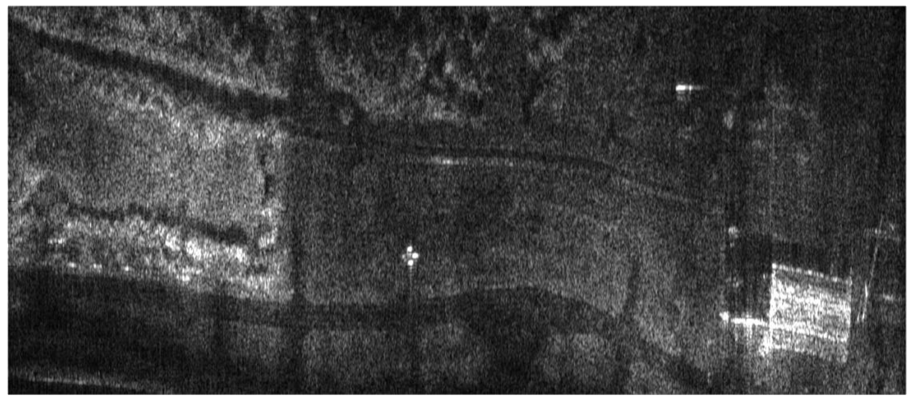
Figure 14.
Radar terrain image obtained with the use of MINS data.

Figure 15.
Radar terrain image obtained using MINS-based MOCO. Overlap bounds are marked white, whereas the red line is an image line chosen to determine SR, PSLR, and ISLR.
Figure 15.
Radar terrain image obtained using MINS-based MOCO. Overlap bounds are marked white, whereas the red line is an image line chosen to determine SR, PSLR, and ISLR.

Figure 16.
Image of the arrow made of corner reflectors: (a) with the INS/GPS-based MOCO, (b) with the MINS-based MOCO; red line—an analyzed row.
Figure 16.
Image of the arrow made of corner reflectors: (a) with the INS/GPS-based MOCO, (b) with the MINS-based MOCO; red line—an analyzed row.

Figure 17.
Normalized amplitude of the selected corner reflector image: (a) with the INS/GPS-based MOCO, (b) with the MINS-based MOCO.
Figure 17.
Normalized amplitude of the selected corner reflector image: (a) with the INS/GPS-based MOCO, (b) with the MINS-based MOCO.

Figure 18.
Normalized amplitude of corner reflector with INS/GPS-based MOCO.

Figure 19.
Normalized amplitude of corner reflector with MINS-based MOCO.

Figure 20.
MINS trajectories for flight no 2 (multicolor r line) and INS trajectory (blue line).

Figure 21.
Image of the arrow made of corner reflectors for flight no 2: (a) with the INS-based MOCO, (b) with the MINS-based MOCO; red line—an analyzed row.
Figure 21.
Image of the arrow made of corner reflectors for flight no 2: (a) with the INS-based MOCO, (b) with the MINS-based MOCO; red line—an analyzed row.

Figure 22.
Normalized amplitude of the selected corner reflector image: (a) with the INS-based MOCO, (b) with the MINS-based MOCO.
Figure 22.
Normalized amplitude of the selected corner reflector image: (a) with the INS-based MOCO, (b) with the MINS-based MOCO.


Table 1.
MINS results for flight no 1.
| Instance Number | Duration [s] | |
|---|---|---|
| 1 | 3.425 | 0.354 |
| 2 | 2.342 | 0.350 |
| 3 | 5.486 | 0.342 |
| 4 | 6.966 | 0.338 |
| 5 | 6.249 | 0.311 |
| 6 | 5.590 | 0.253 |
| 7 | 2.053 | 0.295 |
Table 2.
Parameters of the quality of the selected synthetic aperture radar (SAR) image.
| Source of Corrections | Parameter of Image Quality | ||||
|---|---|---|---|---|---|
| IC (↑) | E (↓) | SR [m] (↓) | PSLR [dB] (↓) | ISLR [dB] (↓) | |
| none | 4.06 | 14.43 | 0.913 | −5.17 | −5.85 |
| INS | 8.32 | 13.83 | 0.304 | −8.45 | −10.50 |
| INS/GPS | 7.56 | 13.94 | 0.119 | −2.99 | 1.52 |
| MINS | 8.01 | 13.84 | 0.278 | −8.57 | −10.68 |
Table 3.
Parameters of the quality of the selected SAR image.
| Source of Corrections | Parameter of Image Quality | ||||
|---|---|---|---|---|---|
| IC (↑) | E (↓) | SR [m] (↓) | PSLR [dB] (↓) | ISLR [dB] (↓) | |
| none | 4.69 | 13.83 | – | – | – |
| INS | 6.00 | 13.01 | 0.195 | −4.12 | −2.58 |
| INS/GPS | 5.78 | 12.96 | 0.366 | −1.92 | −0.40 |
| MINS | 6.50 | 12.91 | 0.187 | −6.80 | −5.46 |
Publisher’s Note: MDPI stays neutral with regard to jurisdictional claims in published maps and institutional affiliations. |
© 2020 by the authors. Licensee MDPI, Basel, Switzerland. This article is an open access article distributed under the terms and conditions of the Creative Commons Attribution (CC BY) license (http://creativecommons.org/licenses/by/4.0/).
Share and Cite
MDPI and ACS Style
Labowski, M.; Kaniewski, P. Multi-Instance Inertial Navigation System for Radar Terrain Imaging. Remote Sens. 2020, 12, 3639. https://0-doi-org.brum.beds.ac.uk/10.3390/rs12213639
AMA Style
Labowski M, Kaniewski P. Multi-Instance Inertial Navigation System for Radar Terrain Imaging. Remote Sensing. 2020; 12(21):3639. https://0-doi-org.brum.beds.ac.uk/10.3390/rs12213639
Chicago/Turabian StyleLabowski, Michal, and Piotr Kaniewski. 2020. "Multi-Instance Inertial Navigation System for Radar Terrain Imaging" Remote Sensing 12, no. 21: 3639. https://0-doi-org.brum.beds.ac.uk/10.3390/rs12213639
Note that from the first issue of 2016, this journal uses article numbers instead of page numbers. See further details here.