
Link Budget Analysis with Laser Energy for Time Transfer Using the Ajisai Satellite


Korea Astronomy and Space Science Institute, Daejeon 34055, Korea
*
Author to whom correspondence should be addressed.
Remote Sens. 2021, 13(18), 3739; https://0-doi-org.brum.beds.ac.uk/10.3390/rs13183739
Submission received: 23 August 2021
/
Revised: 13 September 2021
/
Accepted: 15 September 2021
/
Published: 18 September 2021
(This article belongs to the Special Issue Space LiDAR Technologies and Applications)
Abstract
:Two-way Laser Time Transfer (TLTT) using the Ajisai satellite has been considered as a more accurate and stable time transfer technique than existing methods; TLTT requires the kHz laser pulses to decrease the systematic restrictions for TLTT realization. However, because of the low energy of the kHz laser pulses as well as the low cross section due to the small size of the Ajisai reflecting mirror, the link budget is an important issue to establish the TLTT link between two ground stations. In this study, the TLTT link budget is investigated to find the optimal laser pulse energy via analysis of geometric effects using 30 days of orbital data of the Ajisai satellite from 29 March 2021 within a ground network consisting of four stations located in three countries. The geometric configuration reduces the TLTT link budget by three orders of magnitude due to free space loss, atmospheric transmission, and effective cross section; then, the pulse energy is required to be much higher than laser ranging to the Ajisai satellite. It is shown from the simulation that a few tens of mJ level of pulse energy at the transmitting station is quite enough for TLTT realization.
1. Introduction
Laser Time Transfer (LTT) is the one of the laser applications in space, which allows time synchronization between two remote clocks using a short laser pulse. This technique can provide the high-precision time transfer with accuracy of sub-nanosecond level that is required to enhance performance in astronomy, space geodesy, timekeeping systems and deep space exploration. LTT has been recognized as a more accurate and stable time synchronization technique than other time transfer methods using radio waves, such as the two-way satellite time and frequency transfer (TWSTFT) technique [1] and GNSS common view observation.
Laser Synchronization from Stationary Orbit (LASSO) was the first experimental project in space for optical time transfer using an artificial satellite. The LASSO instruments package onboard the geostationary MeteoSat-3 satellite was designed to compare the time at two or more laser ranging sites using a one-way up-link laser pulse transmitted from the ground. In 1992, this experiment not only successfully performed inter-continental time transfer between McDonalds (Texas, USA) and Grasse (France) with an accuracy on the order of nanoseconds but also validated the feasibility of the LTT concept [2].
The Time Transfer by Laser Link (T2L2) experiment is the follow-on mission to LASSO, and the T2L2 instrument was the one of experimental passengers on the Jason 2 mission, launched in June 2008 [3,4,5]. The T2L2 payload records the arrival time of laser pulses from Satellite Laser Ranging (SLR) stations at the scale of the on-board oscillator and provides these data for time synchronization through post-processing with laser ranging data of the stations. The accuracy of the T2L2 instrument is essential to translate the raw information into time transfer data and to facilitate the calibration process. Through the rigorous data processing, T2L2 showed the capability of time transfer with stability better than 1 picosecond over 1000 s and accuracy of 100 picoseconds [6].
Another approach for LTT is Two-way Laser Time Transfer (TLTT) using the reflective mirrors on satellites such as the Ajisai satellite. The Ajisai satellite is a Japanese geodetic satellite launched in 1986, which is covered with not only corner cube reflectors (CCRs) for laser ranging but also mirror panels for photometric observation. The Ajisai satellite has a long mission life, and its mirrors are made of an alloy of aluminum that has no lifetime limit [7].
The TLTT technique using the Ajisai’s reflective mirrors as a two-way zero-delay optical transponder was proposed and initial analysis including configuration, calibration and link budget were provided by Kunimori et al. [8]. As with the TWSTFT technique, each SLR station transmits a laser pulse to the other station using the reflective mirror on the Ajisai’s satellite and measures the firing and arriving time of reflected pulse at both stations with the internal system delays to determine the time difference for the synchronization of atomic clocks with the accuracy of 10−10~10−11 order.
However, there are two critical issues to realize this concept using the Ajisai satellite. One is the limited hitting probability at the right time when employing the low repetition rate laser pulse in traditional SLR systems. The individual mirror of the Ajisai was designed to flash three times per rotation (~2 s) and the passage duration time of the reflected mirror, that is, the footprint passage time of the reflection beam of Ajisai’s curved mirror at the receiving station, is 5 to 10 milliseconds. Therefore, the repetition rate of the laser pulse is required to be at least 200 Hz, which is a few tens of times faster than that of traditional systems, to hit the mirror at every footprint passage. Another issue is the weak strength of reflected signals due to the very small size of the Ajisai’s reflective mirror, and the variation of the effective cross section resulting from the phase angle of the reflective mirror when dealing with signals from two ground stations. Daniel et al. [9] simulated the laser link via individual mirrors, based on the Ajisai’s spin model, between the Matera (Italy) and Graz (Austria) SLR systems for TLTT, and the result showed an average signal strength of 3.46 photoelectrons at the received station (Graz) when the parameters of laser source (532 nm) at the transmitting station are the high energy level of 100 mJ and low repetition rate of 10 Hz.
Even though there are some difficulties to realize this concept, it can provide a more accurate and stable time transfer compared to that of the T2L2 technique because there are no error sources, such as modeling error of onboard time comparison unit and the long-term variation of transponder delay. This approach has received considerable attention as a potential technology to allow very high-precision and accuracy of 100 picoseconds or even better.
The TLTT concept using the Ajisai satellite was re-formulated as a kilohertz (kHz) SLR application by Otsubo et al. [10]. The high repetition rate of laser pulses based on kHz laser technology provides full capability for the laser pulse to hit the Ajisai’s reflective mirror at the right time, and the event timer at the kHz SLR station can record multiple stop events for TLTT; these were the key problems involved in the TLTT approach using the Ajisai satellite. However, the low signal strength of received photons at the receiving station is still a serious issue for real application.
In general, the repetition rate and the pulse energy of a laser system have a reciprocal relationship. This means that a high repetition rate usually decreases the pulse energy for a fixed average power. The low pulse energy of the kHz laser system makes the expected number of photons less than 1 photon/footprint passage of the Ajisai satellite. To overcome this restriction, several methods to improve system performance were proposed, which include (i) increasing the laser energy, (ii) enhancing the optical efficiency, and (iii) using a modified algorithm allowing a single signal transfer [10].
For TLTT realization based on kHz laser technology, there are two critical elements (i.e., geometric configuration and laser pulse energy) to determine the signal strength of received photons. Therefore, the effects of geometric configuration are analyzed in this paper for the TLTT application in terms of the laser link budget, which plays a large role in the variation of the TLTT link budget. Additionally, an analytical approach to find the optimal laser energy for the kHz laser system is investigated based on the threshold of detection probability and the operation concept of the network for TLTT application.
2. TLTT Link Budget
2.1. Link Budget Equation for TLTT
The radar link equation is used to calculate the mean signal flux at an SLR receiver, which is expressed as the mean number of photoelectrons () in the SLR system [11].
where is the wavelength of the laser pulse, is the Planck’s constant, and is the speed of light. The link budget equation consists of the system dependent terms and the geometric configuration terms. The system dependent terms include the laser pulse energy , the transmit optics efficiency (, the transmitter gain (), the receiving area of the telescope () with receiving optics efficiency (), the quantum efficiency of the photon detector (), and the cross section of satellite’s CCRs ). The terms that correspond to the geometric configuration are the free-space loss in the laser travelling path ), atmospheric attenuation (), and cirrus cloud effects ().
The TLTT approach for laser time transfer using the Ajisai satellite has two main differences in calculating the link budget when compared to the general SLR observation. The first is that there are two ground stations for transmitting and receiving the laser signal, respectively, the other is the cross section of Ajisai’s reflective mirror used for TLTT application, which is very much smaller than the CCRs on the satellite and is affected by the phase angle of the satellite between the two ground stations. The reflective mirror on Ajisai is a small part of the satellite surface, with a virtual radius of 8.5 m; the average size of the reflective mirrors is 0.04 m2 [8]. Therefore, we need to take into account these two characteristics in the link budget equation to realize the TLTT technique using the Ajisai satellite.
2.1.1. Free Space Loss and Atmospheric Effects for TLTT
The geometric configuration consisting of one satellite and two SLR stations for the TLTT technique changes depending on the time. Free space loss and atmospheric effect in the laser link budget equation are affected by changes of geometric configuration, which are functions of slant range and zenith angle between satellite and ground station.
In the case of the free space loss term, we can simply replace the two slant ranges in Equation (1) with the slant ranges between the transmitting station and satellite () and the slant range between the remote receiving station and satellite (), respectively. Atmospheric attenuation and cirrus cloud cover are the main effects that decrease the intensity of electromagnetic waves propagating through the Earth’s atmosphere, and have to be considered separately for the transmitting and receiving stations when using the TLTT technique because these values are dependent on the zenith angle of each station.
The atmospheric attenuation at the altitude of the ground station above sea level () is given approximately by [11]:
where is the sea-level atmospheric attenuation, which is the function of wavelength () and the sea-level atmospheric visibility (), is a visibility scale height, and is the zenith angle of the satellite as observed at the station. The mean cirrus transmission achieved from the experiment with assumption of no cirrus clouds 50% of the time is given by [11]:
where is the cirrus cloud thickness.
Therefore, the link budget equation for TLTT can be introduced from the ordinary SLR link budget equation with slight modification to account for the effect of geometric configuration, as in:
where , , , and are the atmospheric attenuation and the mean cirrus transmission at the transmitting (t) and receiving (r) stations, respectively.
2.1.2. Effective Cross Section of Ajisai’s Mirror for TLTT
The optical flux returned to the receiving station by a satellite is a function of satellite optical cross section () and distance between satellite and receiving point. The effective target cross section is defined as:
where is the scattering steradian solid angle of target, is the target reflectivity, and is the target area.
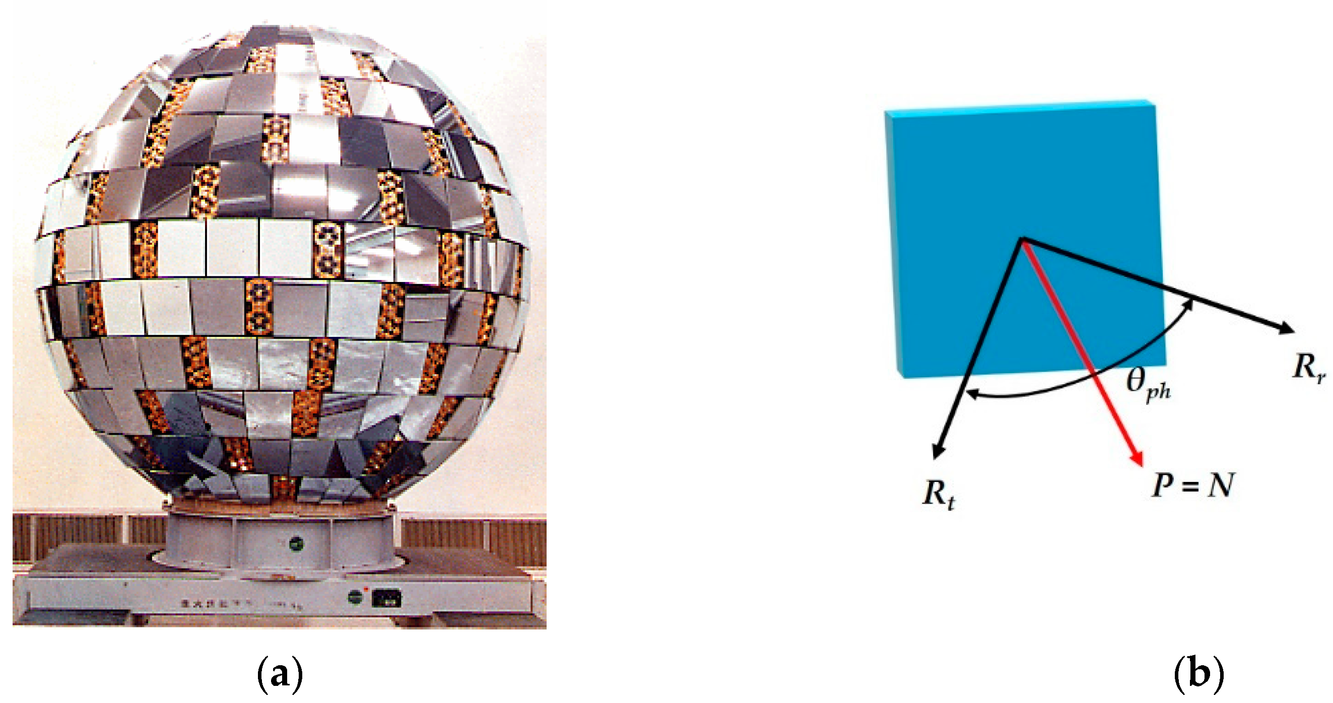
The spin axis and spin rate of the Ajisai satellite change slowly due to the Earth’s gravitation, magnetic fields and solar irradiation; prediction of the rotational phase of the Ajisai at the sub degree level is nearly impossible, although a highly accurate spin model of Ajisai does exist [8]. This means that the geometrical configuration between the reflecting mirror of the Ajisai and the ground stations is difficult to calculate. To simplify this complicated problem, we take into consideration a simple analytical model in which the normal vector (N) of the reflective convex mirror of the Ajisai satellite is coincident with the phase vector (P), which is defined as the product of two vectors pointing to the transmitting () and receiving () ground stations with respect to the satellite, as shown in Figure 1.
The phase angle () can be calculated using the following position vector equation
Then, the effective target cross section in Equation (5) can be modified to account for the specular reflection of the mirror as in:
Finally, the link budget equation for TLTT with Ajisai’s reflecting convex mirror can be expressed as Equation (8):
2.2. Minimum Required Laser Energy for TLTT
The Geiger-mode avalanche photodiode (GmAPD) is considered for TLTT weak signal detection due to its single-photon detection capability, which follows Poisson statistics in the photon detection model. Background noise coming from both the sky and the Sun interrupts the signal photon detection because the GmAPD detector is triggered by the first few photons arriving at the detector, regardless of whether these are signal photons or background noise. However, background noise is made negligible by not only employing three types of filters in the receiver (i.e., special spatial, spectral and temporal filters), but also by executing the TLTT link during the night, when the intensity of background noise, at 532 nm of laser wavelength, is about five orders of magnitude smaller than in the daytime [12].
The probability that the received photons will create primary photoelectrons on the GmAPD is expressed as:
where is the number of primary photoelectrons that trigger the avalanche process. To allow single-photon detection, the GmAPD is biased above the breakdown voltage with a much higher gain than that used in the linear-mode APD and triggered when at least a single photoelectron is generated. According to Equation (9), the probability of generating no primary photoelectrons is . Therefore, the probability of triggering the detector (i.e., detection probability) is given by:
Considering that the number of laser pulses is fired from the ground station during the observation time interval , the expected number of events () triggering the detector (in other words, successful counts of TLTT link) is expressed statistically as:
where is the repetition rate of laser pulses. The threshold of detection probability in which the count of the TLTT link occurs once during the observation time interval (i.e., ), can be calculated by:
where is the threshold number of received photons to make one successful TLTT link, which corresponds to the minimum energy level () needed to create more than one photoelectron in the given time interval. It is worth noting that the average number of received photons is linearly proportional to the transmitting laser energy. Using Equations (8), (10) and (12), and can be written, in terms of average number of received photons and the transmitting laser energy, by:
3. Simulation Results
3.1. Simulation Parameters
3.1.1. Characteristics of Ajisai for TLTT
Ajisai is the nickname of the Japanese geodetic satellite EGS (Experimental Geodetic Satellite) operated by the Japan Aerospace Exploration Agency (JAXA). The satellite was launched into the circular orbit with an altitude of 1500 km and inclination of 50 degrees in Aug. 1986; it was one of three payloads of the test flight on the H-1 rocket [7].
The shape of the Ajisai is a hollow sphere with a 2.15 m diameter; it is covered with 1436 corner cube reflectors for laser ranging and 318 mirror panels for photometric observation. The surface size and radius of curvature of the reflective mirrors are 393 cm2 at maximum and 8.35~8.70 m, respectively. These mirrors are placed in 14 rings on the surface of the Ajisai satellite with 2.15 m diameter; the latitude angle of each mirror on the 8.5 m radius sphere is maintained on the surface of Ajisai satellite to reduce the actual radius to 1.08 m. The allocation of convex mirrors on Ajisai was designed to provide solar reflection to the ground observer at 3 times per rotation period by installing three mirrors in the same ring to have an identical latitude angle [7,10]. The key satellite parameters used for TLTT simulation are listed in Table 1.
The initial spin rate of the Ajisai was 40 rotations per minute (rpm), chosen to stabilize the attitude of the hollow sphere; this rotation can provide observability of flashing light at a repetition rate of 2 times per second for the reflecting mirror configuration. The satellite spin period has slowly changed due to the effects from gravitation, solar radiation and irradiation pressure [13,14,15]. Following a recent analysis, the Ajisai spin period was found to double every 46.6 years; the current value is approximately 2.4 s [16,17]. Therefore, the current rate of light flashing has changed to 1.5 Hz for a spin rate of 25 rpm, from 2 Hz for 40 rpm.
The reflectivity of Ajisai’s mirror is a key parameter that determines the performance of the observation of reflected light. The convex mirrors of Ajisai were coated by silicon oxide for protection on the aluminum base; the reflectivity was in a range from 0.85 to 0.92 (mean 0.898) before launch. Based on analysis of the hyper temporal light curves of the Ajisai over 2 years from October 2015, the specular coefficients of the reflecting mirror were determined in the range of 82.3% to 88.2% (mean 85.3%), which shows that there has been a very small degradation of reflectivity of Ajisai’s convex mirrors over the last 30 years.
3.1.2. Parameters of SLR Stations in the Target Network
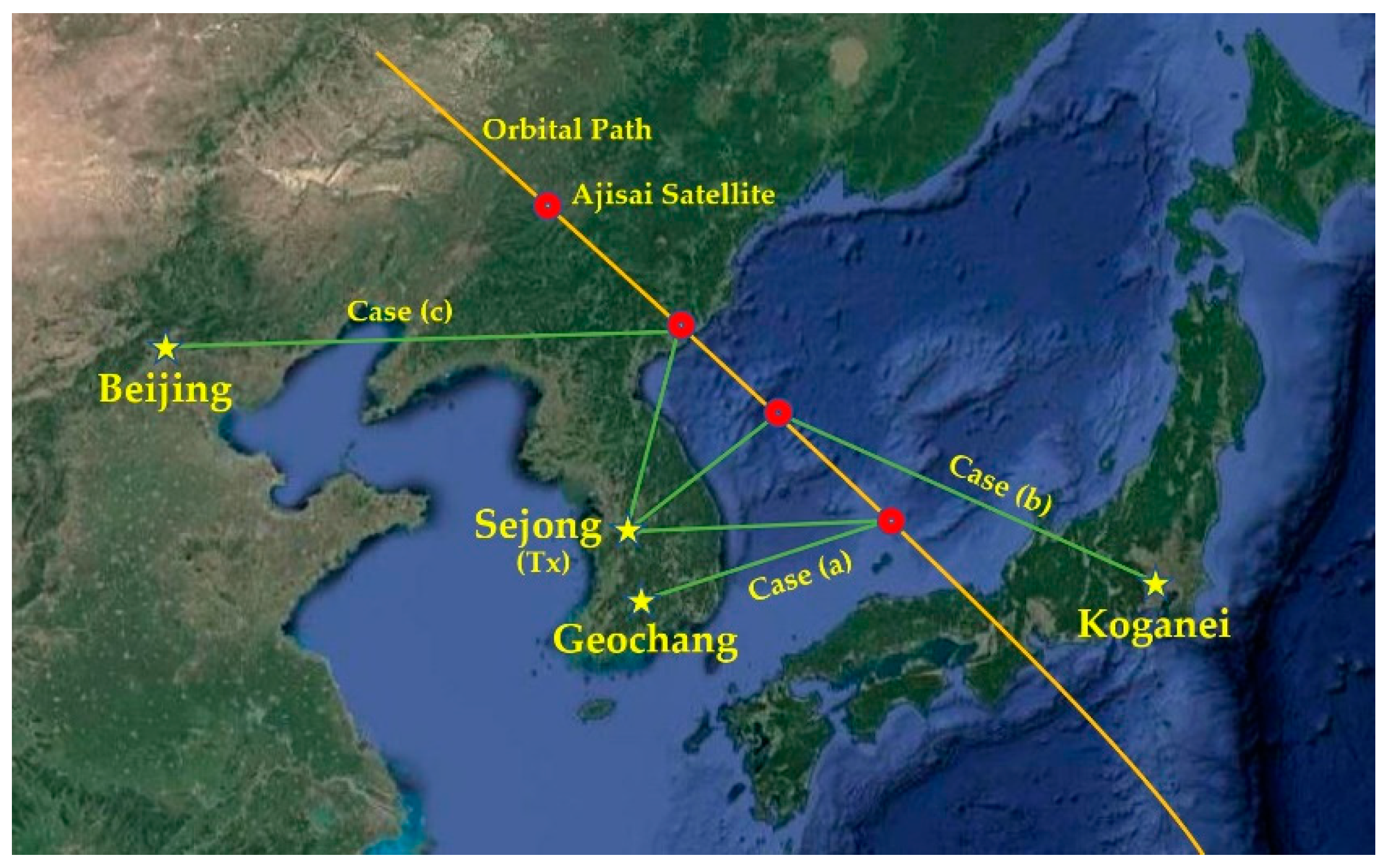
We selected 4 SLR stations from among 10 ILRS (International Laser Ranging Service) sites in the East Asia region—Sejong, Geochang, Beijing and Koganei—as the target network to analyze the link budget in terms of number of received photons for TLTT using the Ajisai satellite. All the parameters of the four SLR stations used in this simulation, including the geographical position, are shown in Table 2.
The Sejong SLR station was chosen as a laser transmitting station for the TLTT simulation because it has the smallest transmitting telescope aperture (0.1 m) and highest repetition rate of laser pulse (5 kHz at maximum). The key parameters of the Sejong SLR station affected to the laser link budget of Equation (8) are the laser pulse energy () of 2.5 mJ, transmit optic efficiency () of 92.3%, beam divergence half angle () of 5 arcsec, and beam pointing error () of 5 arcsec [12].
The other three SLR stations were selected as receiving stations for TLTT implementation in the target network, with three combinations of one transmitting and one receiving station, as shown in Figure 2; these stations are located around the Sejong station at distances of 117.3 km (Geochang), 1056 km (Beijing) and 1098.7 km (Koganei).
3.2. Results
To analyze the effects of geometric configuration on the laser link budget and to find the optimal laser energy at the transmitting station for the TLTT application, we simulated the link budget and the detection probability for 30 days from 29 Mar. 2021, based on the ephemeris dataset of the Ajisai satellite.
The parameters related to the geometric configuration, including slant range, zenith angle and phase angle, were calculated, along with the position of the Ajisai satellite estimated from the SGP4 orbit propagator, the Two Line orbital Elements (TLE) of Ajisai and the Earth Orientation Parameter (EOP) [19,20,21]. Considering a clear sky, we adopted the atmospheric attenuation coefficient of σ(λ, V, 0) = 0.25 for 1.5 km of visibility scale height, the visibility scale height of = 1.2 km and cirrus cloud thickness of = 1341 m in Equations (2) and (3). In total, 102 night passes have the common view for all three geometric combinations consisting of one transmitting (Sejong) station, three receiving stations and the Ajisai satellite, for 20 degrees of elevation cut off angle.
3.2.1. Effects of Geometric Configuration
Since the geometric configuration consisting of the Ajisai satellite and the two ground stations has more complicated effects on the TLTT link budget than those of ordinary SLR observation, we investigated the effect of the geometric configuration in terms of slant range, zenith angle and phase angle to analyze the capability of time synchronization via TLTT technique.
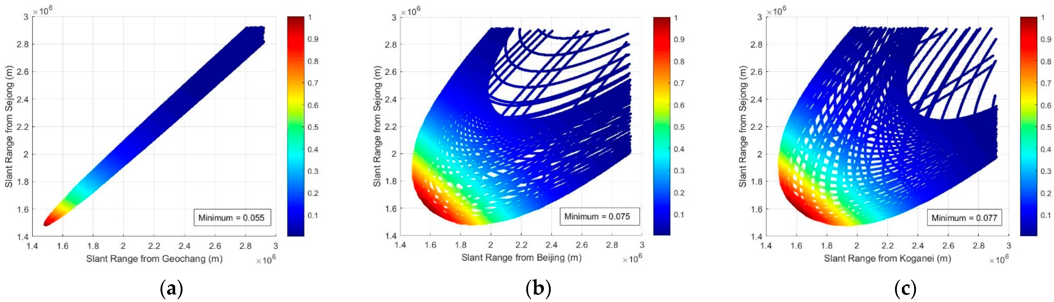
The energy of electromagnetic waves is inversely proportional to the square of the distance between source and target (i.e., slant range) in free space; it also decreases proportionally to the atmospheric propagation angle between the satellite and SLR station (i.e., zenith angle). The peak value of the geometric term due to these two effects is obtained when the slant range and zenith angle to the Ajisai satellite from the two stations are at their minimum, and the ratios of these minimum values are 5.5%, 7.5%, and 7.7%, respectively, of the peak value of each combination case during the simulation period, as shown in Figure 3.
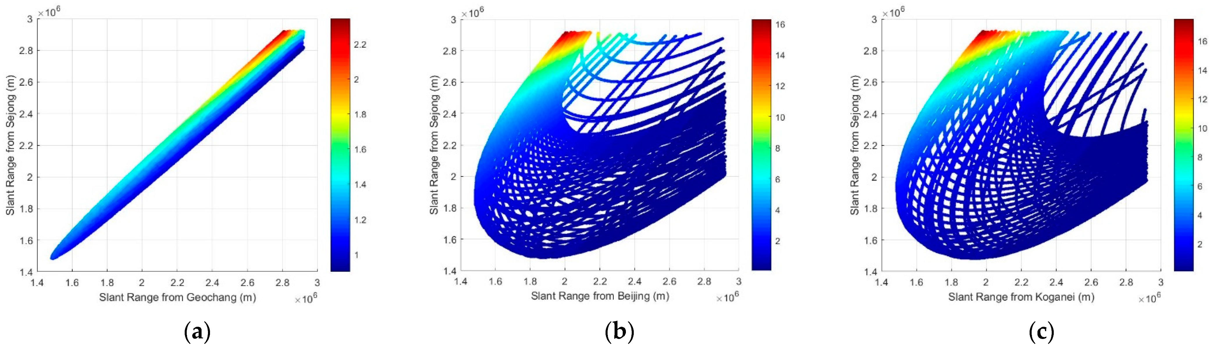
In order to validate the impacts of these effects on the link budget compared to ordinary SLR observation, the ratios of geometric terms were analyzed; these are defined as the relative size of Equation (4) for the TLTT link (i.e., Sejong-Ajisai-three stations) with respect to Equation (1) for the SLR link (i.e., Sejong-Ajisai-Sejong), neglecting other terms in the link budget. Figure 4 shows that the ratio is in a range of 0.05% to 17.5% for the three combination cases, depending on the position of the Ajisai satellite and ground stations; the largest value of each case increases with the distance of the receiving station from the transmitting station. This means that the TLTT link budget is significantly affected (by two orders of magnitude) by the free space loss and atmospheric transmission.
Another term affected by the geometric configuration in the TLTT link budget is the effective cross section of target, which is the function of the phase angle between the target satellite and the two ground stations, as in Equation (7). The maximum cross section of the target satellite is achievable when the transmitting and receiving paths are exactly the same (= 0). This case is usually applied to calculate the laser link budget for tracking space objects not equipped with CCRs [22,23].
The effective cross section of the Ajisai satellite varies from 771.1 to 725.1 m2 during the simulation period, with phase angle of 0.83~40.02 degrees for the three geometric combination cases. In the simulation, the minimum value of the effective cross section is in the range of 93.9% to 99.9% when compared to the peak value in each configuration. The cross section has less influence on the laser link budget than does the geometric effect resulting from the free space loss and atmospheric transmission.
In conclusion, the geometric effects coming from the variation of slant range, zenith angle and phase angle for the TLTT link using the Ajisai satellite reduce the link budget by three orders of magnitude, as shown in Figure 5, when compared to the peak value of TLTT link budget during the simulation period.
3.2.2. Optimal Laser Energy
It is essential to investigate the optimal laser energy of the transmitting SLR station in the simulation network for TLTT application using the Ajisai satellite. Therefore, we analyzed the detection probability to establish the TLTT link under the condition of the given system parameters and geometric configurations during the observable paths. Using Equation (14), we also analyzed the minimum laser energy corresponding to the threshold of detection probability at each epoch to receive one photoelectron. It is noteworthy that the minimum laser energy provides one chance to trigger the detector or establish the successful TLTT link during the passage duration time of 5 msec at minimum.
As shown in Figure 6a, the peak values of detection probability for the three combinations are smaller than the threshold of the detection probability ( = 0.2) for the 1 kHz repetition rate of laser pulses and the passage duration time of 5 msec. This means that there is no chance to successfully establish the TLTT link in the target network during the simulation period. The required or minimum laser energy, which makes the detection probability at each epoch equal to the threshold value during the reflecting duration of Ajisai’s mirror, reaches approximately one thousand times the original transmitting laser energy ( =2.5 mJ), as shown in Figure 6b. The minimum laser energy is mainly caused by geometric effects with the same order analyzed in the previous section, because the peak value of the detection probability is close to the threshold (i.e., ) for each combination.
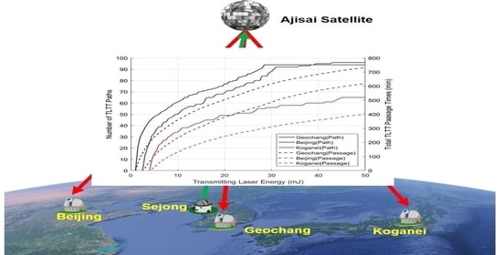
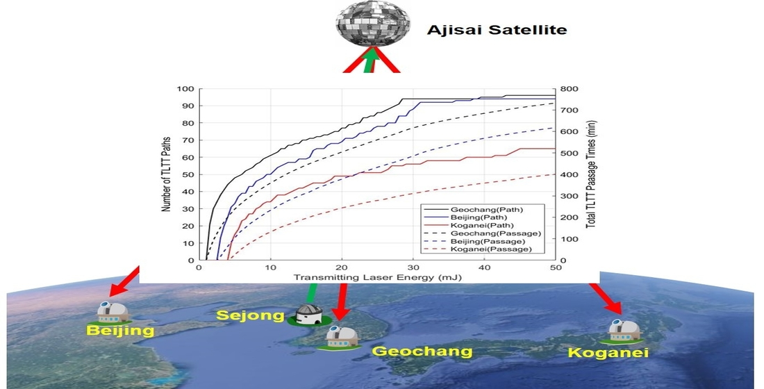
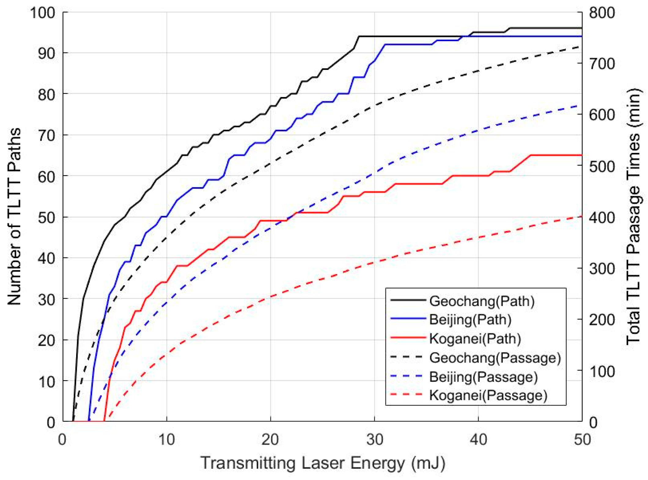
For the analytical approach to finding the optimal laser energy for the TLTT link in the target network, the number of TLTT paths (i.e., TLTT link available paths) and the total TLTT passage times, and the TLTT link available times in the TLTT path were also simulated in terms of changing the transmitting laser energy.
As shown in Figure 7, the number of TLTT paths and the total passage time to allow TLTT link increase gradually to 96 paths and 732.5 min for Geochang station when the laser energy of 50 mJ is employed, which is 20 times the original energy of the transmitting laser at the Sejong SLR station. The averaged TLTT passage time per TLTT path at the Geochang SLR station is 7.6 min; this is quite enough time to receive the signal reflected by the Ajisai’s convex mirror over 570 times (i.e., 7.6 min × 60 s × 1.25 Hz). For the Sejong-Beijing and Sejong-Koganei combinations with transmitting laser energy of 50 mJ, the number of TLTT paths and total TLTT passage times to allow TLTT link are 94 paths with 618.1 min and 65 paths with 400.7 min, respectively, as shown in Table 3.
The optimal laser energy of the transmitting SLR station in the target network can be determined from the simulation results based on the operational concept of the TLTT application. If the averaged chance of the TLTT link is required to be more than one time per day in the target network, the laser energy of the Sejong SLR station should increase from 2.5 mJ to 10.0 mJ because Sejong-Koganei has the minimum number of TLTT paths, at 34 orbital paths, enabling the TLTT link for the period of 30 days.
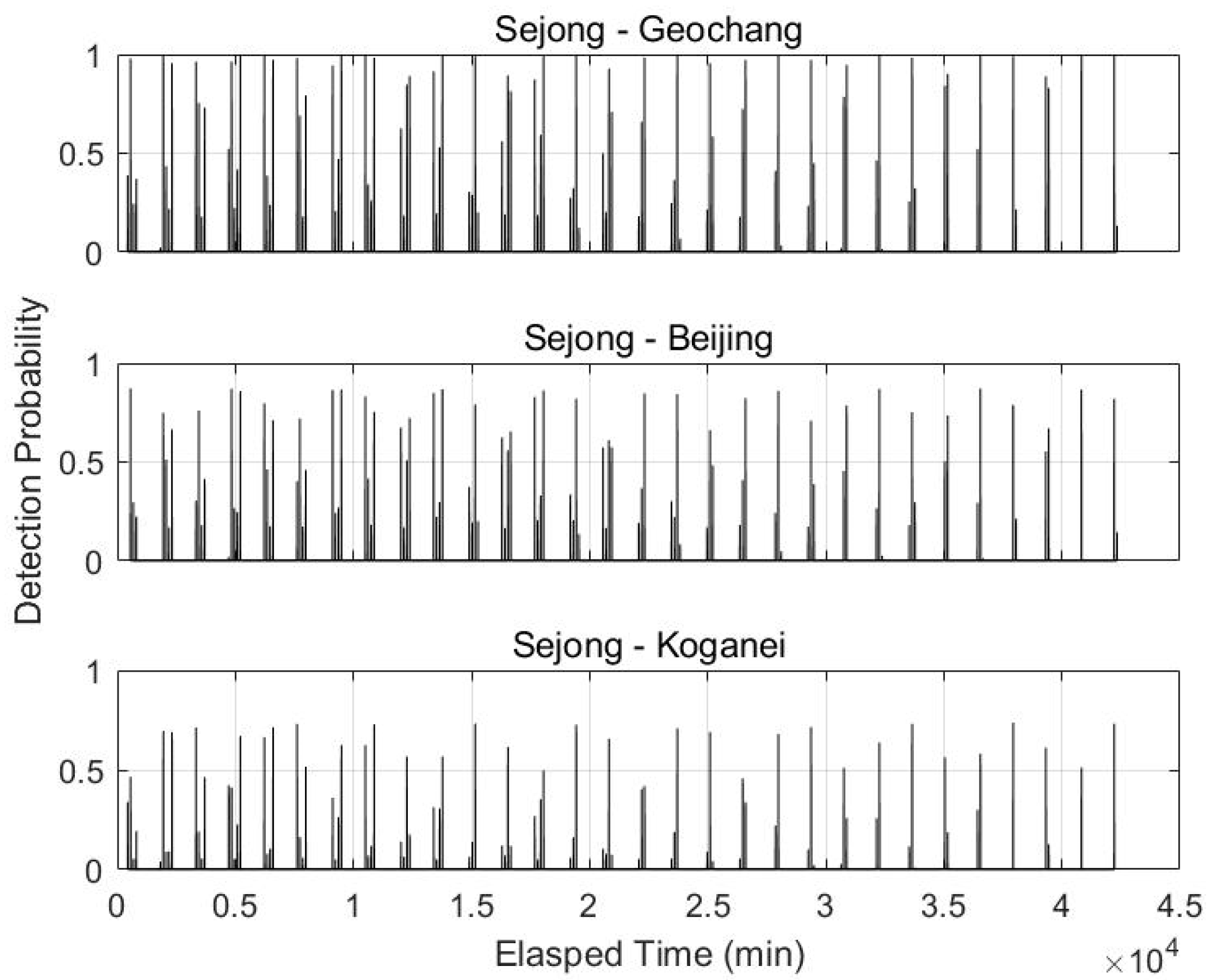
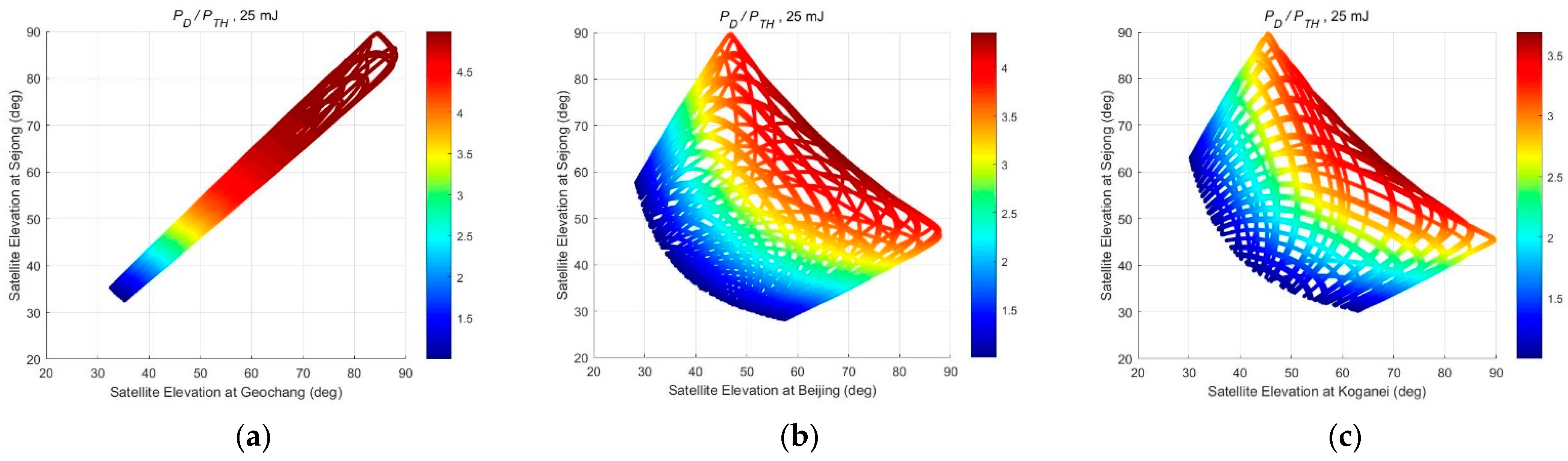
Figure 8 and Figure 9 show the time series of detection probability and the ratio of more than one between the detection probability and its threshold (i.e., ), respectively, when employing a laser energy of transmitting station of 25 mJ, which was used at the Graz SLR station to track space debris with kHz repetition [23]. It is worth noting that this ratio indicates that the TLTT link occurs more than once during the duration of the light flash.
The TLTT link is available over the 30 degrees of satellite elevation from the receiving station, where the ratio of detection probability is near to 1 and its maximum values are 4.98, 4.36 and 3.68 for Geochang, Beijing and Koganei, respectively. These values can be interpreted as the maximum number of photoelectrons received at each station for the passage duration time of 5 msec. In these cases, the number of TLTT paths and averaged TLTT passage times per path at the Geochang SLR station are 86 paths (84% of total observable paths) and 6.5 min. These values are 78 paths, 5.6 min and 51 paths, 5.5 min for Beijing and Koganei, respectively, as shown in Table 3.
4. Discussion
The purpose of this paper is to investigate an analytical approach to finding the optimal laser energy of a transmitting station via analysis of the geometric effects on the TLTT link budget for TLTT implementation using the Ajisai satellite.
The minimum geometric terms of space loss, atmospheric attenuation and cirrus cloud cover in the TLTT link budget have values of 0.055%, 0.075% and 0.077%, respectively, when compared to the peak values of each combination. The peak values can be obtained when the slant range and zenith angle of receiving path are at minimum under the maximum zenith angle of the transmitting path. Another term affected by the geometric configuration is the effective cross section of the Ajisai’s convex mirror, which has a range of 93.9%~99.9% when compared to the peak value of effective cross section at the minimum phase angle of each combination. Consequently, the geometric effects reduce the TLTT link budget by three orders of magnitude when compared to the peak value of the TLTT link budget in the simulation; the cross section effect of the Ajisai’s convex mirror is relatively smaller than other geometric effects coming from free space loss and atmospheric degradation. The reduced value of TLTT link budget increases the required laser energy to receive one photoelectron by the same order at every epoch during the entire TLTT passage time, because the peak value of the TLTT link budget in the target network is close to the critical value for TLTT link establishment.
The chance of establishing a TLTT link can be determined as the ratio between the detection probability and the threshold value = 0.2 for 1 kHz repetition rate of laser pulse and the passage duration time of 5 msec. When employing the original value of laser energy = 2.5 mJ at Sejong SLR station, all the detection probabilities are less than the threshold ratio (i.e., . This means that there is no chance to establish the TLTT link and zero TLTT path in the target network during the simulation period. When the laser energy of the transmitting station increases to = 25 mJ, the ratio of the detection probability improves 3–5 times for each combination, which can be interpreted as the maximum number of photoelectrons to receive at each station; the TLTT paths also increase to 50% of total observable paths during the simulation period.
By increasing the laser energy of the transmitting station from 2.5 mJ to 50 mJ, the number of TLTT paths increases from 0% to 94.1% of the total observable paths; total TLTT passage times gradually increase from 0% to 66.4% of the total passage times for all observable paths in the period of 30 days with 20 degrees cut-off angle. Therefore, using these simulation data, the optimal laser energy of the transmitting station can be selected following the operational concept for TLTT implementation (i.e., frequency of TLTT paths and total TLTT passage times) in the target network.
It was demonstrated that a few tens of mJ level of laser pulse energy at the transmitting station is quite enough for TLTT realization in the target network, and that optimal laser energy can be selected through an analytical approach based on not only the operation concept of the TLTT network but also the threshold of detection probability.
Author Contributions
Conceptualization, J.U.P.; Formal analysis, J.U.P. and M.C.; Software, J.U.P. and H.-C.L.; Writing—original draft, J.U.P.; Writing—review and editing, H.-C.L. and K.-P.S.; Project administration, M.C. All authors have read and agreed to the published version of the manuscript.
Funding
This research received no external funding.
Institutional Review Board Statement
Not applicable.
Informed Consent Statement
Not applicable.
Data Availability Statement
All data generated or analyzed during this study are included in this article.
Acknowledgments
This work was supported by the Korea Astronomy and Space Science Institute through the project “Operation of Observation Facilities for Space Object Surveillance” funded by the Ministry of Science and ICT (MSIT) of the Korean government.
Conflicts of Interest
The authors declare no conflict of interest.
References
- Kirchner, D. Two-Way Time Transfer via Communication Satellites. Proc. IEEE 1991, 79, 983–990. [Google Scholar] [CrossRef]
- Freelance, P.; Veillet, C. Operation and data analysis in the LASSO experiment. Metrologia 1995, 32, 27–33. [Google Scholar] [CrossRef]
- Fridelance, P.; Samain, E.; Veillet, C. T2L2—Time Transfer by Laser Link: A New Optical Time Transfer Generation. Exp. Astron. 1997, 7, 191–207. [Google Scholar] [CrossRef]
- Vrancken, P. Characterization of T2L2 (Time Transfer by Laser Link) on the Jason 2 Ocean Altimetry Satellite and Micrometric Laser Ranging. Ph.D. Thesis, Université de Nice, Sophia-Antipolis, Nice, France, 2008. [Google Scholar]
- Samain, E.; Weick, J.; Vrancken, P.; Para, F.; Albanese, D.; Paris, J.; Torre, J.-M.; Zhao, C.; Guillemot, P.; Petitbon, I. Time transfer by laser link—The T2L2 experiment on Jason-2 and further experiments. Int. J. Mod. Phys. D 2008, 17, 1043–1054. [Google Scholar] [CrossRef] [Green Version]
- Samain, E.; Vrancken, P.; Guillemot, P.; Fridelance, P.; Exertier, P. Time transfer by laser link (T2L2): Characterization and calibration of the flight instrument. Metrologia 2014, 51, 503–515. [Google Scholar] [CrossRef] [Green Version]
- Sasaki, M.; Hashimoto, H. Launch and Observation Program of the Experimental Geodetic Satellite of Japan. IEEE Trans. Geosci. Remote Sens. 1987, GE-25, 526–533. [Google Scholar] [CrossRef]
- Kunimori, H.; Takahashi, F.; Itabe, T.; Yamamoto, A. Laser ranging application to time transfer using geodetic satellite and to other Japanese space programs. In Proceedings of the 8th international Workshop on Laser Ranging Instrumentation, Annapolis, MD, USA, 18–22 May 1992; pp. I-34–I-42. [Google Scholar]
- Kucharski, D.; Kirchner, G.; Otsubo, T.; Kunimori, H.; Jah, M.K.; Koidl, F.; Bennett, J.C.; Lim, H.; Wang, P.; Steindorfer, M.; et al. Hypertemporal photometric measurement of spaceborne mirrors specular reflectivity for Laser Time Transfer link model. Adv. Space Res. 2019, 64, 957–963. [Google Scholar] [CrossRef]
- Otsubo, T.; Kunimori, H.; Gotoh, T. New Application for Khz Laser Ranging: Time Transfer Via Ajisai. In Proceedings of the 15th international Workshop on Laser Ranging, Canberra, Australia, 15–20 October 2006; pp. 420–424. [Google Scholar]
- Degnan, J.J. Millimeter Accuracy Satellite Laser Ranging: A Review. In Contributions of Space Geodesy to Geodynamics: Technology; Smith, D.E., Turcotte, D.L., Eds.; AGU: Washington, DC, USA, 1993; Volume 25, pp. 133–162. [Google Scholar]
- Lim, H.; Seo, Y.; Na, J.; Bang, S.; Lee, J.; Cho, J.; Park, J.H.; Park, J. Tracking Capability Analysis of ARGO-M Satellite Laser Ranging System for STSAT-2 and KOMPSAT-5. J. Astron. Space Sci. 2010, 27, 245–252. [Google Scholar] [CrossRef] [Green Version]
- Kucharski, D.; Kirchner, G.; Otsubo, T.; Lim, H.; Bennett, J.; Koidl, F.; Kim, Y.; Hwang, J. Confirmation of gravitationally induced attitude drift of spinning satellite Ajisai with Graz high repetition rate SLR data. Adv. Space Res. 2016, 57, 983–990. [Google Scholar] [CrossRef]
- Kucharski, D.; Kirchner, G.; Otsubo, T.; Koidl, F. The impact of solar irradiation on Ajisai’s spin period measured by the Graz 2 kHz SLR system. IEEE Trans. Geosci. Remote Sens. 2010, 48, 1629–1633. [Google Scholar] [CrossRef]
- Hattori, A.; Otsubo, T. Time-varying solar radiation pressure on Ajisai in comparison with LAGEOS satellite. Adv. Space Res. 2019, 63, 63–72. [Google Scholar] [CrossRef]
- Otsubo, T.; Amagai, J.; Kunimori, H.; Elphick, M. Spin motion of the Ajisai satellite derived from spectral analysis of laser ranging data. IEEE Trans. Geosci. Remote Sens. 2000, 38, 1417–1424. [Google Scholar] [CrossRef]
- Kirchner, G.; Hausleitner, W.; Crisrea, E. Ajisai spin parameter determination using Graz kilohertz satellite laser ranging data. IEEE Trans. Geosci. Remote Sens. 2007, 45, 201–205. [Google Scholar] [CrossRef]
- International Laser Ranging Service. Available online: https://ilrs.gsfc.nasa.gov/network/stations/index.html (accessed on 2 April 2021).
- Vallado, D.; Crawford, P. SGP4 Orbit Determination. In Proceedings of the AIAA/AAS Astrodynamics Specialist Conference, Honolulu, HI, USA, 18-21 August 2008; p. AIAA-2008-6770. [Google Scholar] [CrossRef]
- CelesTrak: Current NORAD Two-Line Element Sets. Available online: https://www.celestrak.com/NORAD/elements (accessed on 29 March 2021).
- International Earth Rotation and Reference System Service. Available online: https://www.iers.org/IERS/EN/Science/EarthRotation/EOP.html (accessed on 29 March 2021).
- Zhang, Z.; Yang, F.; Zhang, H.; Wu, Z.; Chen, J.; Li, P.; Meng, W. The use of laser ranging to measure space debris. Res. Astron. Astrophys. 2012, 12, 212–218. [Google Scholar] [CrossRef] [Green Version]
- Kirchner, G.; Koidl, F.; Friederich, F.; Buske, I.; Völker, U.; Riede, W. Laser measurements to space debris from Graz SLR station. Adv. Space Res. 2013, 51, 21–24. [Google Scholar] [CrossRef]
Figure 1.
(a) Ajisai satellite (courtesy of JAXA) and (b) phase angle model of Ajisai’s convex mirror.
Figure 1.
(a) Ajisai satellite (courtesy of JAXA) and (b) phase angle model of Ajisai’s convex mirror.

Figure 2.
Target ground network for TLTT implementation with three combination cases between laser transmitting station (Sejong) and receiving stations on the google maps.
Figure 2.
Target ground network for TLTT implementation with three combination cases between laser transmitting station (Sejong) and receiving stations on the google maps.

Figure 3.
Ratio of geometric term to peak value including free space loss, atmospheric attenuation and cirrus cloud transmission in TLTT link budget. (a) Sejong−Geochang, (b) Sejong−Beijing and (c) Sejong−Koganei.
Figure 3.
Ratio of geometric term to peak value including free space loss, atmospheric attenuation and cirrus cloud transmission in TLTT link budget. (a) Sejong−Geochang, (b) Sejong−Beijing and (c) Sejong−Koganei.

Figure 4.
Ratio of geometric effects including free space loss and atmospheric transmission in TLTT link budget with respect to ordinary SLR observation. (a) Sejong−Geochang, (b) Sejong−Beijing and (c) Sejong−Koganei.
Figure 4.
Ratio of geometric effects including free space loss and atmospheric transmission in TLTT link budget with respect to ordinary SLR observation. (a) Sejong−Geochang, (b) Sejong−Beijing and (c) Sejong−Koganei.

Figure 5.
Ratio of geometric term in TLTT link budget to peak value including free loss, atmospheric transmission and effective cross section in time domain. (a) Sejong−Geochang and (b) Sejong−Koganei.
Figure 5.
Ratio of geometric term in TLTT link budget to peak value including free loss, atmospheric transmission and effective cross section in time domain. (a) Sejong−Geochang and (b) Sejong−Koganei.
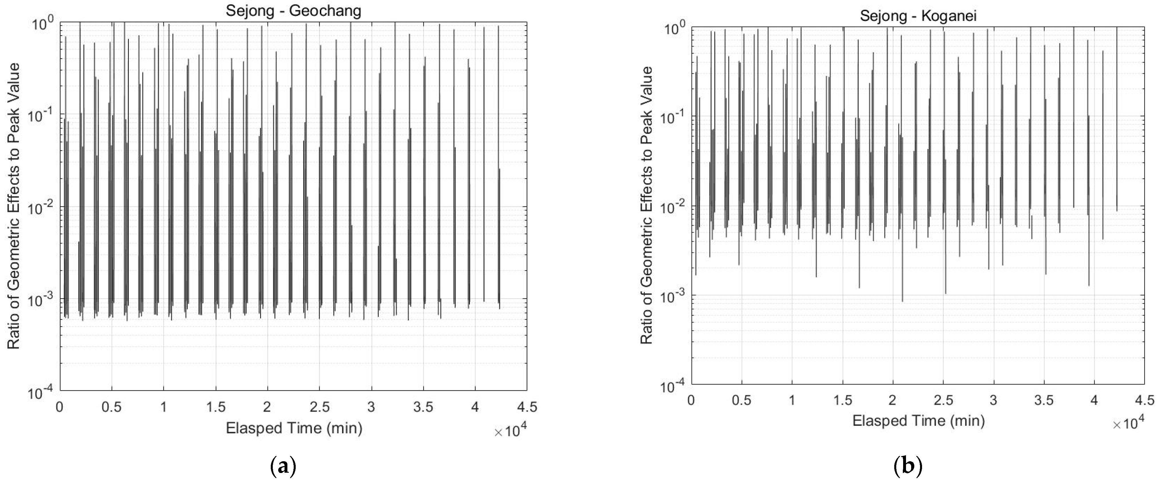
Figure 6.
Time series of (a) detection probability and (b) minimum laser energy corresponding to threshold of detection probability.
Figure 6.
Time series of (a) detection probability and (b) minimum laser energy corresponding to threshold of detection probability.
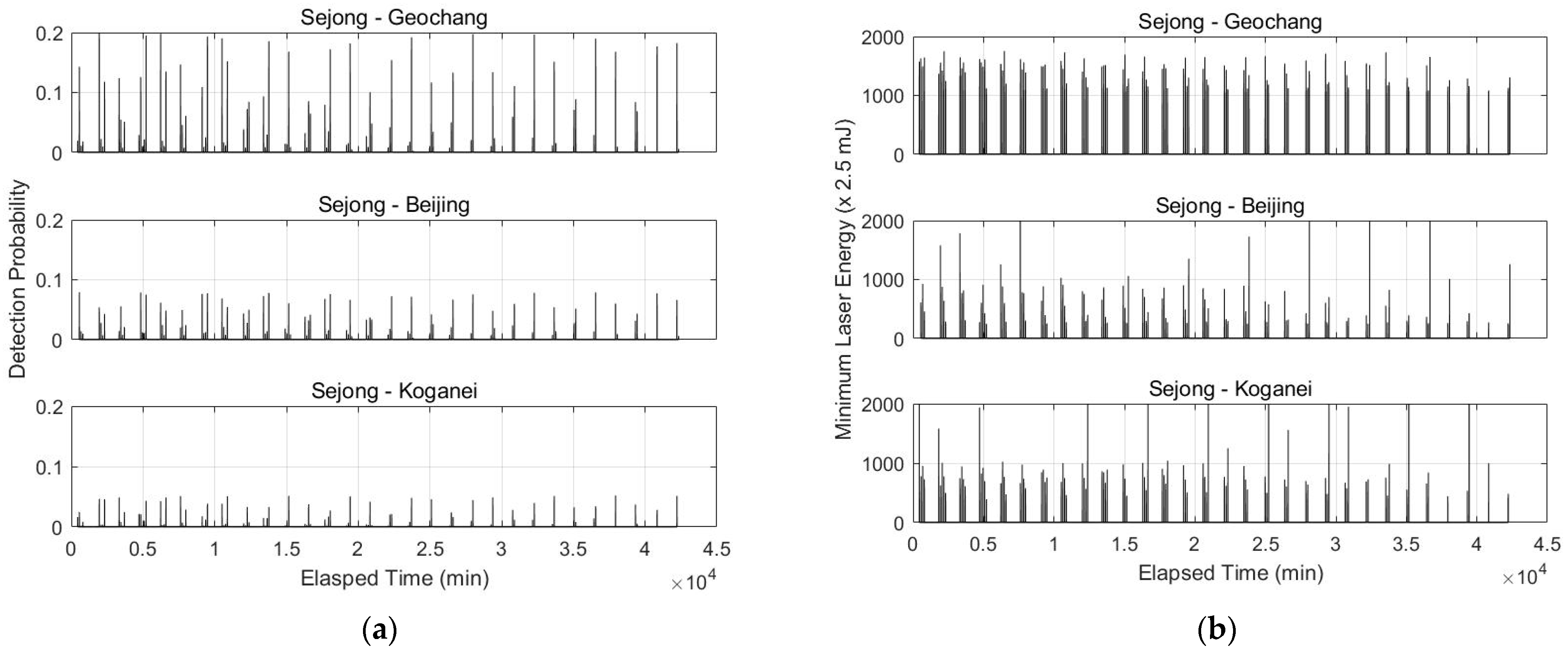
Figure 7.
Number of TLTT paths and total TLTT passage times to enable TLTT link in terms of transmitting laser energy.
Figure 7.
Number of TLTT paths and total TLTT passage times to enable TLTT link in terms of transmitting laser energy.

Figure 8.
Time series of detection probability with 25 mJ energy at transmitting station (Sejong).

Figure 9.
Ratio of detecting probability to threshold value for receiving one photoelectron from Ajisai’s reflective mirror in satellite elevation space. (a) Sejong−Geochang, (b) Sejong−Beijing and (c) Sejong−Koganei.
Figure 9.
Ratio of detecting probability to threshold value for receiving one photoelectron from Ajisai’s reflective mirror in satellite elevation space. (a) Sejong−Geochang, (b) Sejong−Beijing and (c) Sejong−Koganei.


Table 1.
Key parameters of Ajisai for TLTT simulation.
| Number of mirrors | 318 pieces |
| Curvature of mirrors | 8.35~8.7 m (8.5 m for simulation) |
| Reflectivity | 0.85~0.92 (0.85 for simulation) |
| Duration of light flash | 5 msec |
| Rate of flashing | 1.25 Hz (2 Hz at initial) |
| Spin rate | 25 rpm (40 rpm at initial) |
Table 2.
Parameters of 4 SLR stations in the target network [18].
Table 2.
Parameters of 4 SLR stations in the target network [18].
| Parameters | Sejong | Geochang | Beijing | Koganei | ||
|---|---|---|---|---|---|---|
| Laser | λ | Wavelength | 532 nm | 532 nm | 532 nm | 532 nm |
| Pulse energy | 2.5 mJ | 15 mJ | 1 mJ | 50 mJ | ||
| Pulse width | 50 ps | 9.2 ps | 200 ps | 35 ps | ||
| Repetition rate | 1 KHz | 60 Hz | 1 KHz | 20 Hz | ||
| Telescope | Tx Primary mirror | 0.1 m | 1.0 m | 0.16 m | 1.5 m | |
| Tx Secondary mirror | - | 0.25 m | - | |||
| Transmit optic efficiency | 92.3% | 75% | 70% | 30% | ||
| Beam divergence angle | 5~200 arcsec | 8 arcsec | <103 arcsec | 5 arcsec | ||
| Beam pointing error | <5 arcsec | <4 arcsec | <5 arcsec | <5 arcsec | ||
| Rx Primary mirror | 0.4 m | 1.0 m | 0.60 m | 1.5 m | ||
| Rx Secondary mirror | 0.1 m | 0.25 m | - | - | ||
| Receiver optic efficiency | 64.9% | 35% | 70% | 10% | ||
| Detector | Quantum efficiency | 20% | 20% | 20% | 15% | |
| Position | Longitude | 127.3029E | 127.9201E | 115.8920E | 139.489E | |
| Latitude | 36.5210N | 35.5902N | 39.6069N | 35.710N | ||
| Altitude | 176.415 m | 934.063 m | 82.300 m | 121.820 m | ||
Table 3.
Number of TLTT paths and total TLTT passage times with respect to transmitting laser energy.
Table 3.
Number of TLTT paths and total TLTT passage times with respect to transmitting laser energy.
| Laser Energy | Number of TLTT Paths | Total TLTT Passage Times (min) | ||||
|---|---|---|---|---|---|---|
| Geochang | Beijing | Koganei | Geochang | Beijing | Koganei | |
| 2.5 mJ | 0(0%) | 0(0%) | 0(0%) | 0 | 0 | 0 |
| 5.0 mJ | 48(47%) | 33(33%) | 15(16%) | 238.3 | 104.4 | 26.0 |
| 10.0 mJ | 61(60%) | 50(50%) | 34(36%) | 359.7 | 232.5 | 131.5 |
| 25.0 mJ | 86(84%) | 78(79%) | 51(54%) | 561.6 | 433.2 | 278.6 |
| 50.0 mJ | 96(94%) | 94(95%) | 65(68%) | 732.5 | 618.1 | 400.7 |
| Observable | 102 | 99 | 95 | 1163.8 | 930.5 | 837.6 |
Publisher’s Note: MDPI stays neutral with regard to jurisdictional claims in published maps and institutional affiliations. |
© 2021 by the authors. Licensee MDPI, Basel, Switzerland. This article is an open access article distributed under the terms and conditions of the Creative Commons Attribution (CC BY) license (https://creativecommons.org/licenses/by/4.0/).
Share and Cite
MDPI and ACS Style
Park, J.U.; Lim, H.-C.; Sung, K.-P.; Choi, M. Link Budget Analysis with Laser Energy for Time Transfer Using the Ajisai Satellite. Remote Sens. 2021, 13, 3739. https://0-doi-org.brum.beds.ac.uk/10.3390/rs13183739
AMA Style
Park JU, Lim H-C, Sung K-P, Choi M. Link Budget Analysis with Laser Energy for Time Transfer Using the Ajisai Satellite. Remote Sensing. 2021; 13(18):3739. https://0-doi-org.brum.beds.ac.uk/10.3390/rs13183739
Chicago/Turabian StylePark, Jong Uk, Hyung-Chul Lim, Ki-Pyoung Sung, and Mansoo Choi. 2021. "Link Budget Analysis with Laser Energy for Time Transfer Using the Ajisai Satellite" Remote Sensing 13, no. 18: 3739. https://0-doi-org.brum.beds.ac.uk/10.3390/rs13183739
Note that from the first issue of 2016, this journal uses article numbers instead of page numbers. See further details here.