
Recent Advances in the GPR Detection of Grouting Defects behind Shield Tunnel Segments

1
Key Laboratory of Geotechnical and Underground Engineering of Ministry of Education, Department of Geotechnical Engineering, Tongji University, Shanghai 200092, China
2
Department of Geotechnical Engineering, College of Civil Engineering, Tongji University, Shanghai 200092, China
3
State Key Laboratory of Geomechanics and Geotechnical Engineering, Institute of Rock and Soil Mechanics, Chinese Academy of Sciences, Wuhan 430071, China
4
Guangxi Nonferrous Survey & Design Institute, Nanning 530031, China
*
Author to whom correspondence should be addressed.
Remote Sens. 2021, 13(22), 4596; https://0-doi-org.brum.beds.ac.uk/10.3390/rs13224596
Submission received: 14 October 2021
/
Revised: 6 November 2021
/
Accepted: 12 November 2021
/
Published: 16 November 2021
(This article belongs to the Special Issue Review of Application Areas of GPR)
Abstract
:Injecting grout into the gaps between tunnel shield segments and surrounding rocks can reduce ground subsidence and prevent ground water penetration. However, insufficient grouting and grouting defects may cause serious geological disasters. Ground penetrating radar (GPR) is widely used as a nondestructive testing (NDT) method to evaluate grouting quality and determine the existence of defects. This paper provides an overview of GPR applications for grouting defect detection behind tunnel shield segments. State-of-the-art methodologies, field cases, experimental tests and signal processing methods are discussed. The reported field cases and model test results show that GPR can detect grouting defects behind shield tunnel segments by identifying reflected waves. However, some subsequent problems still exist, including the interference of steel bars and small differences in the dielectric constants among media. Recent studies have focused on enhancing the signal-to-noise ratio and imaging methods. Advanced GPR signal processing methods, including full waveform inversion and machine learning methods, are promising for detecting imaging defects. Additionally, we conduct a preliminary experiment to investigate environmental noise, antenna configuration and coupling condition influences. Some promising topics, including multichannel configuration, rapid evaluation methods, elastic wave method scanning equipment for evaluating grout quality and comprehensive NDT methods, are recommended for future studies.
1. Introduction
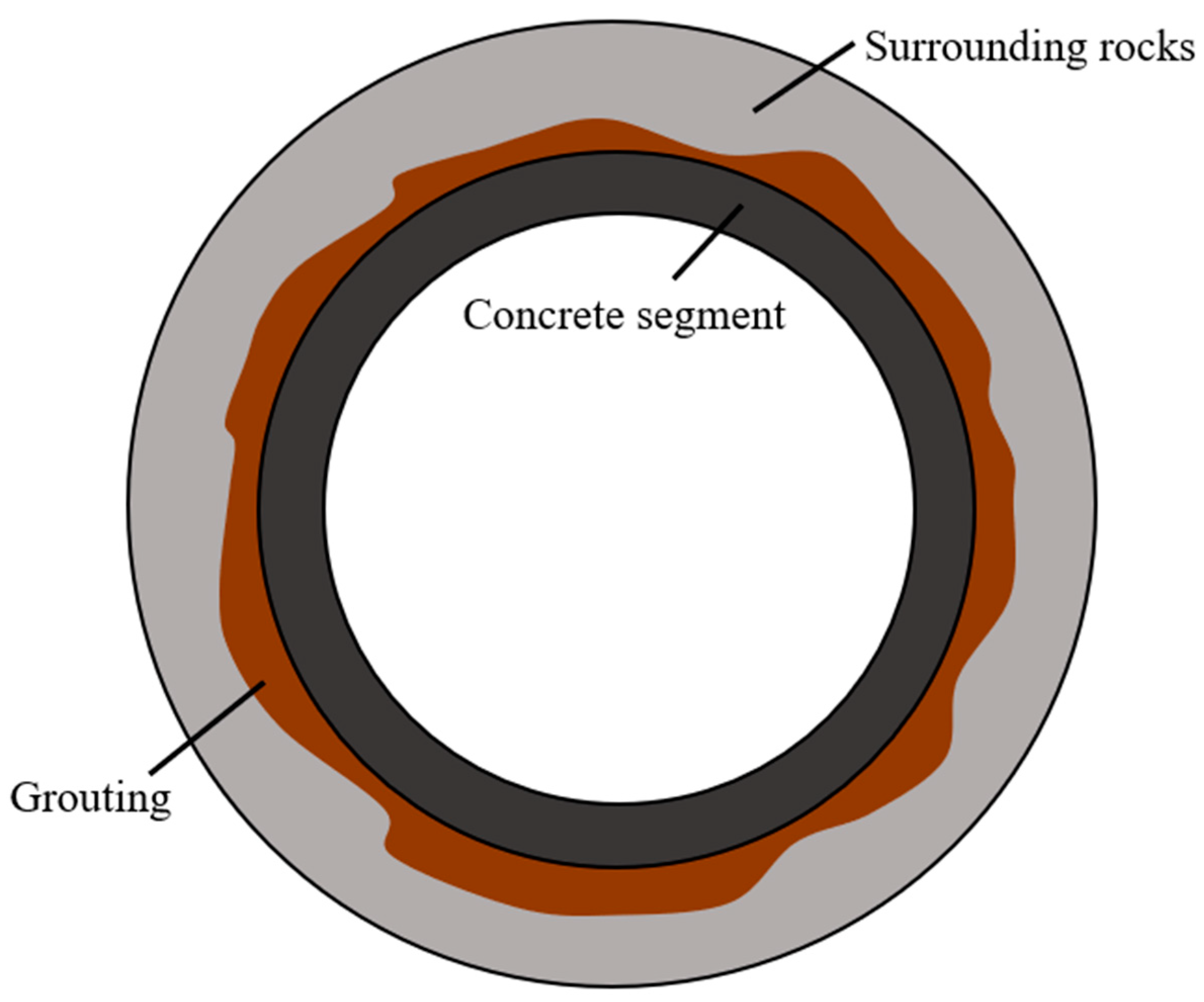
In recent decades, shield construction has become a developed construction technology [1]. Currently, shield construction is widely used in soft soil tunnel constructions, such as saturated soft clay, silty soft soil, saturated sandy silt, and silty sand. In shield construction, by injecting grout to fill the gap between the pipe wall and the ground, the formation loss can be effectively reduced. Grouting reduces ground subsidence and prevents the penetration of ground water into the tunnel [2,3]. As shown in Figure 1, fast-setting grout is injected into the soil, thus generating a soil-concrete mixture with enhanced ground resistance to the developing movement due to lining expansion [4]. However, during grouting, the grouting quality is difficult to observe. Therefore, quantitatively controlling the grouting amount is challenging. Grouting defects, such as uneven filling, insufficient filling and nonuniformity, may cause serious geological disasters, such as ground water erosion and surface collapse [5,6].
Currently, tunnel construction is based on whether the grouting hole is overflowing or whether the grouting pressure meets the requirements to determine whether the grouting is full [7]. Nondestructive testing (NDT) methods provide a new way to detect the defects behind the segment in tunnels. Among geophysical methods, ground penetrating radar (GPR) is widely recognized as one of the most powerful and useful NDT methods of concrete structure detection [8,9,10,11]. GPR that is used to detect the quality of the tunnel lining and grouting behind tunnel shield segments has two main functions. One function is to detect the gap between the cement wall of the segment and the rock and soil layer, and to determine whether the space is empty or filled with grouting by using the amplitude of the reflected signal and the estimated electromagnetic properties of the medium. The other function is to check whether the tunnel construction results are consistent with the design by considering certain details, such as the distribution of steel bars, the thickness of the lining, and whether there is groundwater leakage.
In detecting grouting defects behind segment walls, GPR has several advantages over other geophysical methods. (1) The large workload of detecting grouting defects requires an efficient and easy-to-implement prospecting method. Therefore, a contact but nondestructive, portable, and fast data acquisition technique is very suitable for grouting defect detection. (2) The main media involved in grouting defects behind segments are concrete, steel rebar, water (in water-bearing defects), air (in dry defects), and rocks. There are reliable differences in the dielectric constant among these media. The interfaces between the media may generate reflected electromagnetic waves very well. (3) To detect grouting defects behind tunnel segments, the required detection depth is usually less than 1 m. GPR is therefore a suitable method because the commonly used GPR has an acceptable attenuation at this depth. Additionally, compared to competing geophysical approaches, GPR has a much higher resolution.
This paper summarizes the research results of using GPR for detecting grouting defects behind shield tunnel segments. Additionally, to provide advice for future NDT research on detecting grouting defects behind shield tunnel segments, this paper includes a forward-looking aspect regarding the research of NDT methods in grouting defect detection.
2. GPR Method
GPR has been commonly used for investigating concrete structures over recent decades [12]. GPR detects underground structures by propagating electromagnetic (EM) waves through materials. The positions of the interfaces between materials with different electrical properties can be inferred by the arrival time of the reflected wave. The wave velocity, attenuation, polarization changes, and redirection of signals are affected by the electric and magnetic properties of the materials. Such signals can be interpreted to help analyze the properties of materials and the geometry of the subsurface. A detailed description of the GPR methodology and theoretical background can be found in [13,14,15,16,17,18]. Additionally, in GPR, numerical simulation is often used as a supplemental tool to help generate realistic big data [19,20,21]. Such data can be used in comparative analysis with field data [22], full waveform inversion [23,24], and machine learning approaches [25].
Typical GPR equipment (Figure 2) consists of two antennas. When the equipment moves over the concrete surface, the transmission antenna sends electromagnetic waves into the subsurface, and the other antenna receives the arriving waves to generate the profile. In concrete structure applications, GPR systems usually operate in the 10–5000 MHz frequency range for different purposes [26]. A lower frequency improves the penetrating ability of EM waves to detect deeper waves, and a higher frequency improves the resolution. In practice, there is a trade-off between accuracy and detection depth [27]. Additionally, the frequency determines the size of the equipment, and the lower the frequency is, the larger the size of the equipment is.
3. GPR Detection of Grouting Defects behind Shield Tunnel Segments
3.1. Experiments and Field Cases
Some studies have been conducted on detecting grouting defects behind shield tunnel segments as shown in Table 1. Most of these studies are field cases and experiments, and numerical simulation is also used as a tool.
The following are field cases and experimental studies that successfully applied GPR to grouting defect detection.
Xie et al. [28] used GPR to evaluate the grouting situation of tunnel segments during the construction of a subway tunnel. In an indoor test, the dielectric constant of the grouting material was determined. Algorithms, such as time and space filtering, defined gain, and absolute value calculation, were proposed to enhance the visibility of GPR data.
Zhang et al. [29] used GPR to detect the thickness of the grouting layer behind the segment. The difference between the grouting and soil was not large enough in the early stage, thus making it difficult to determine the interface. However, after the grouting body had solidified for 40 days, better detection results were obtained. In the tunnel project in the Shanghai soft soil area, the geophysical NDT method is suitable as a long-term structural strength testing and risk assessment method.
Yu et al. [31] used the GPR method to inspect the quality of the grouting behind the tunnel shield segment of the subway tunnel and subsequently verified the feasibility of the GPR method. One aspect of the feasibility of this method is its ability to detect the thickness of the grouting layer behind the segment, and the other is its ability to detect whether there are defects or damages in the grouting layer. A finite difference time-domain numerical simulation was used to carry out auxiliary research. The results show that the thickness of the grouting layer is 30 cm, and the grouting layer has defects, mainly cavities and cracks.
Lalague et al. [33] used GPR to detect the surrounding rock after tunnel lining was completed in model tests and engineering practice. Remote detection of the cavity behind the concrete tunnel lining and detection of the rock falling on the top of the concrete segment from the tunnel roof were achieved. A medium-frequency (1 GHz) air-coupled antenna can meet the needs of detecting boulders (>40 cm), but metal surrounding objects may cause the detection quality to decrease and make the signal more difficult to analyze. Ground-coupled GPR was shown to be the best method for detecting loose rocks around tunnels. A 1.5 GHz antenna was used to detect boulders, and 2.6 GHz was used for the more precise detection of small and medium-sized rocks. The test results show that seven days after grouting is the best time to detect the quality of grouting, and the distance between the transmitting and receiving antennas importantly influences the detection results.
Hu et al. [34] established a full-scale shield tunnel model test platform and used GPR to carry out preset grouting defect detection behind the segment. The distance between transmitting and receiving antennas of 5 cm to 10 cm was shown to achieve the best accuracy in detecting defects behind tunnel shield segments.
Zeng et al. [37] used GPR to establish a detection system that can monitor the grouting situation in real time while the shield machine is tunneling. Synchronous analysis was carried out using a three-dimensional time-domain finite difference approach. The grouting pressure was adjusted in real time according to the GPR detection results. This measure effectively limits uneven ground settlement in urban areas due to grouting problems.
GPR has shown its feasibility in detecting grouting defects behind tunnel shields. According to case studies and experimental studies, using GPR to detect grouting defects behind tunnel shield segments still has some problems [29,35,36,40,41]: (1) the electromagnetic wave penetration ability is poor, especially for higher resolution and high-frequency antenna conditions; (2) the dielectric constant difference between the soil and the grouting material needs to be large enough to better detect the interface; (3) the data depend on experienced experts for interpretation, where complex procedures are required for processing, and (4) the detection interference of the steel bar is very extensive, thus making it difficult to determine the position of the soil and grouting body and the boundary.
3.2. Signal Processing
3.2.1. Signal-to-Noise Ratio Enhancement
In the detection of grouting defects behind tunnel shield segments, the inspection targets are usually the thickness of the grouting layer, the interface between grouting and surrounding rock, and the defects in the grouting body. Except for the targets listed above, the signals caused by all other objects will interfere with the detection. To eliminate interreferences and improve the signal-to-noise ratio (SNR), scholars have performed the following research.
Zhao et al. [42] proposed a “wave field prediction and removal method” to predict the propagation of the GPR wave field, and successfully removed strong scattering and multiples. In addition to predictive deconvolution, the method uses fuzzy Kalman (f-k) filtering and Karhunen–Loève (K-L) filtering. Since the lining segment can be regarded as the known information, including its geometry, dimension, and dielectric parameters, finite-difference time-domain (FDTD) can be used to predict the scattering wave and multiples of lining segment and steel bars within. By subtracting the predicted wave field from the raw GPR record, we precisely abstracted the reflections from objects.
Zhao et al. [22] proposed a GPR image reconstruction method based on Maxwell’s curl equation to eliminate the harmful effects of near-surface diffraction and scattering. This method was applied to the detection of defects behind shield tunnel segments, and the GPR data were processed in a numerical experiment, model experiment, and the construction of Shanghai Metro Line 9. Compared to the conventional Kirchhoff migration method, this method can eliminate the strong scattering of shallow steel bars and make the interface between the grouting layer and the soil more obvious so that deep grouting can be observed more clearly.
Xie et al. [30] used a bandpass filter and K-L filtering to process GPR data, thereby improving the signal-to-noise ratio of the signal. To effectively identify the grouting layer and the abnormal body, it is recommended to select the maximum eigenvalue N = 3 for the K-L filter as the optimal parameter.
3.2.2. GPR Profile Reconstruction
GPR is the mainstream method for detecting the grouting quality behind tunnel shield segments; however, traditional GPR detection can provide only a common offset profile, which cannot meet the requirements of high-precision detection and construction design. The positions of subsurface objects can be estimated from signal data. Depth information can be retrieved when the reflection arrival times are determined from the data [26,43]. In recent decades, seismic signal processing methods and techniques have been adapted into EM wave processing [44,45,46]. In traditional geophysical methods, the migration method is a commonly used approach that can process the signal profile into an image; examples of migration methods include the Kirchhoff integrated wave field extrapolation method [47,48], finite difference method, and shift reference method [49,50]. Grasmueck et al. [51,52] studied 3D GPR image reconstruction based on the migration method. However, these mentioned methods require an accurate background velocity to perform accurate imaging. In recent years, to enhance the GPR detection capability, scholars have proposed imaging methods, such as diffraction tomography (DT) [53,54], range migration (RM) [43,55], and back projection (BP) [56,57].
K-L transformation and F-K Stolt migration were used to improve the radar image and help identify the interface between the grout and the soil [32]. Using these two methods, authors calculated the thickness and spatial distribution of the grouting body behind the tunnel segment wall by using the two-way travel time and radar signals. The results show that the GPR can effectively detect the quality of the grouting body during shield construction. The results show that the GPR can effectively detect the quality of the grouting body during shield construction.
Xie et al. [38] used the bifrequency BP (BBP) method to produce GPR images to detect the quality of tunnel segments after grouting. High-resolution visualization of the grouting body was achieved. During the construction of Shanghai Metro Line 12, it was verified that the BBP imaging method can identify the position of the steel bar in the segment, the shape and thickness of the grouting layer, and the location of the defects in the grouting layer.
3.2.3. Advanced Methods in GPR
Research has shown that quite effective signal processing methods are used in detecting defects behind tunnel shield segments. The purpose of various processing methods is to suppress the scattering interference of steel bars, to amplify the reflection signals of the grouting layer and defects, and to use imaging methods to transform the radar signal into an image of the subsurface distribution. Additionally, advanced techniques have been introduced; these techniques range from image processing to statistical methods (including machine learning). However, thus far, concerning the detection of defects behind tunnel shield segments, GPR signal processing methods have been used to determine the location and scale of the defects and the interface between the grouting layer and surrounding rocks. The results are shown as amplitude images to determine the reflection location.
Full waveform inversion (FWI) is an emerging technique for quantitative, high-resolution imaging used in seismic exploration and GPR investigation [58]. FWI obtains higher-resolution images compared with the traditional GPR profile because FWI employs all information in the received signal data. There are GPR FWI applications in numerical research [59], crosshole investigations [60], and soil moisture mapping [61]. However, FWI has not yet been applied in the GPR detection of defects behind tunnel shield segments. Eisenmann et al. [62] assessed the detectability improvement via synthetic aperture focusing techniques (SAFTs) in GPR concrete structure inspection.
A data-based analysis method for detecting defects behind tunnel shield segments was recently introduced. Statistical analysis is a data-based method. Qin et al. [39] proposed a probabilistic inversion method for using GPR waveform data to infer the thickness of the grouting layer behind the segments and its dielectric constant and conductivity parameters. The sliding window method, Makarov chain Monte Carlo model, and Bayesian theory are used to explore the posterior distribution of the model parameters. Numerical simulation verifies that this method can effectively estimate the thickness of the grouting layer. The influence of modeling error on the inversion results was measured, and a modified likelihood function was used to correct this influence.
As a popular data-based method, machine learning is also applied to GPR processing to detect the location of rebar in tunnel shield segments. Giannakis et al. [25] proposed a machine learning method that can estimate the diameter of the investigated rebar by using amplitude-scan (A-scan) signals. The suggested approach combines neural networks and a random forest regression, and has been trained entirely using synthetic data. The scheme was successfully evaluated with real data. Moreover, the machine learning method was used as an alternative forward solver in FWI [59].
In terms of signal processing, research has shown that attempts have been made to improve the signal-to-noise ratio and suppress steel bar interference and background noise. Imaging and migration methods have been used to determine the scale and location of grouting defects. However, current signal processing methods in grouting defect detection focus on imaging and locating defects. The defect filling material parameters are difficult to obtain. Using the FWI method along with other emerging techniques to determine both location and parameter information is a future research direction.
4. Characteristics of GPR Grouting Defects
In synthetic models, experiments, and field cases, GPR shows its capability in detecting grouting defects behind tunnel shield segments. However, grouting defect detection is still an emerging technique, and GPR detection has some unique features, such as interference in the segment and grouting, and the influence of antenna configuration, coupling mode and frequency. In this chapter, we conducted a series of model tests to support discussions.
GPR detection of grouting defects has some unique issues that differentiate this GPR application from other GPR investigations. In grouting defect detection, the tunnel shield segment structures are designed and basically constant. Additionally, the interferences are mostly from the multiple waves between the segment interface and surface, and the scattering waves from steel bars. Consequently, the interferences in grouting defect detection might be predictable. Thus, preliminary model tests can help us better understand the mechanism, analyze influencing factors, and provide a basis for future applications of GPR detection of grouting defects behind tunnel shield segments. The full-size tunnel shield segment model with preset defects is shown in Figure 3a. The model is composed of 6 segments (as shown in Figure 3b). There are preset defects in the grouting layer, as shown in the flattened illustration (Figure 3c). The defects are made of polyvinyl chloride (PVC) pipes that can be filled with air or water. The surrounding rock is a water-bearing pebble formation. GSSI SIR-4000 GPR equipment was used in the model test with 400 MHz and 900 MHz antennas. Regular and simple processing, including time zero position correction, defined exponential gain, and infinite impulse response (IIR) filtering are applied to amplify the deep signal of defects and improve the SNR.
4.1. Interferences of Metals and Multiples
Unlike other GPR applications, steel bar reflection strongly interferes with the detection of defects behind tunnel shield segments. Other metal objects, such as segment bolts and the surrounding metal materials, may cause serious problems in detection because compared to other media near the tunnel shield segment, metal materials have very large differences in dielectric parameters. The reflection of metal objects is much more intensive than the reflection of defects and grouting layer interfaces and, thus, may result in the invisibility of the detection targets. Thus, researchers designed implements to eliminate the interferences caused by steel bars [22,30,38]. The segment seams and multiples of the horizontal interfaces (the roof and floor of the segment) also interfere with GPR detection.
4.2. Defects’ Filling Material
In the grouting layer, defects appear mostly as voids. The material filling the voids can also influence the detection results. The experiment presented the detection result differences between air-filled defects and water-filled defects. The corresponding test results are shown in Figure 4. When the defects are filled with air, the reflections are much weaker, and some defects are invisible in the profile (marked in Figure 4b) because the dielectric constant difference between the grouting body and air is much smaller than that between the grouting body and water. However, the multiples are more intensive when the defects are filled with water probably because the water infiltrates into the gap between the segment and grouting layer. The reflection is enhanced, and so are the multiples.
Additionally, as the grouting body consolidates, the dielectric constant of the grouting body changes as moisture decreases. The dielectric constant of the grouting body is 34.5 on the third day and 22.5 on the 14th day [29]. Therefore, the inspection results will differ due to grouting consolidation. To obtain the best detection results, a proper time window must be found to avoid intensive multiples and to ensure the available dielectric constant difference between the grouting body and surrounding rock.
4.3. Transmitter-Receiver Configurations
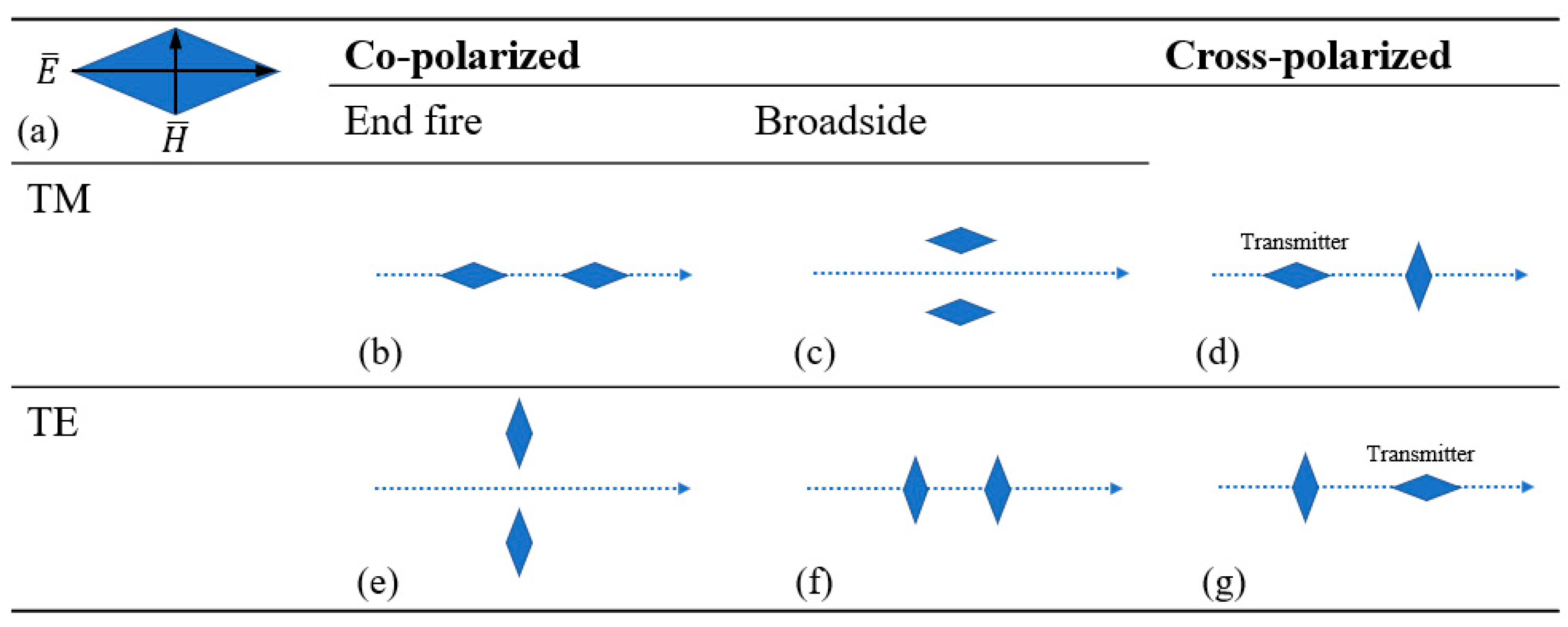
Generally, when the GPR is scanning, the system keeps moving with the transmitting antenna and receiving antenna, progressing back and forth. Alternatively, the transmitter-receiver configuration can be different [63,64]. According to study [63], Figure 5 gives a sketch of all the possible geometries between the two antennas (Figure 5). is the direction of the electric vector, and is the direction of the magnetic vector. The blue arrow indicates the survey direction. Antennas can have electric field vectors oscillating along (TM mode) or perpendicular (TE mode) to the survey direction.
Preliminary experiments in the test model (Figure 3) were employed to verify how the transmitter-receiver configuration influences the GPR detection results. The transmitter-receiver configurations were set as electric field vectors, oscillating parallel (Figure 5b) and perpendicular (Figure 5e) to the survey direction. The frequency is 900 MHz. The grouting defects were filled with water to obtain more obvious results.
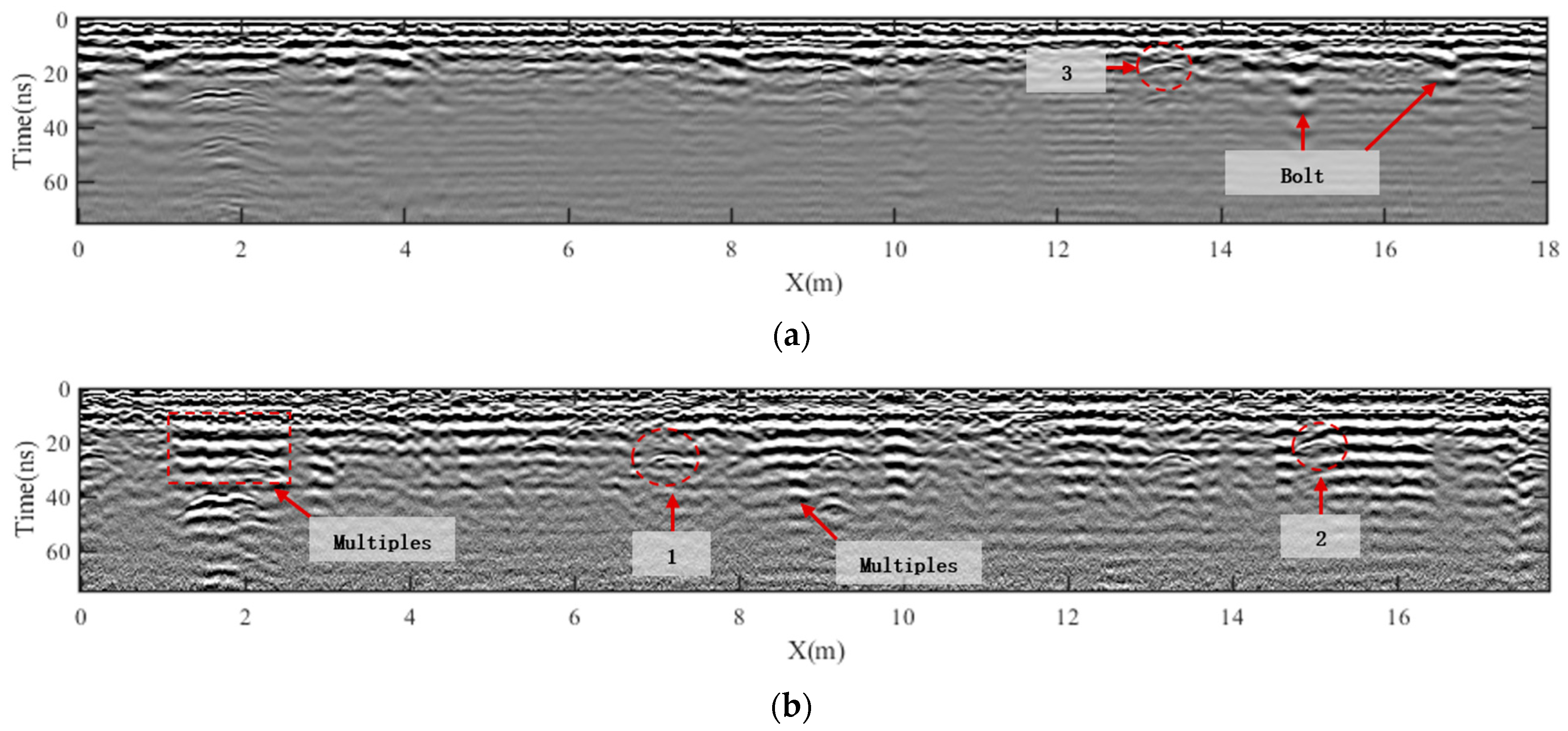
The test results are shown in Figure 6. When the electric field vector oscillates along the survey direction, the multiples have weaker influences, and the defects are easier to observe. When the electric field vector is perpendicular to the survey direction, the multiples are stronger. Some defects (1 and 2 in Figure 6a) are covered by multiples. Moreover, the segment seams are observed clearly. The segment seams are regarded as interferences, although they can sometimes be used as marks to help determine object locations in the profile. These two configurations can support each other in the analysis. Thus, an investigation combining different transmitter-receiver configurations can help enhance the information attained from detecting defects behind tunnel shield segments.
The seismic method and GPR use similar physical mechanisms but are sensitive to different physical properties. In seismic methods, multiple transmissions and multiple receipts are commonly used to collect data [63]. The distance between the transmitting and receiving antennas also significantly influence detection performance [34]. Using radar in array form can improve the quality of the information collected [65]. There are many developed techniques regarding the signal processing of array-collected data. In seismic exploration, there are techniques for obtaining velocity profiles [66]. In medical imaging, sensors are attached to the surface with an adhesive. The transducer transmits ultrasonic waves and collects the reflected waves to reconstruct the profile of the human body structure. Beamforming imaging is a well-developed medical method [67,68,69] that also shares similar physical mechanisms with NDT techniques. Beamforming assigns a delay time to each receiver and superimposes each delayed signal to obtain the image amplitude of the target point (Figure 7). The beamforming method can also suppress ground waves.
4.4. Coupling Condition
Two coupling forms are commonly used in GPR investigations: air coupling and ground coupling [33]. Air-coupled GPR systems are more efficient and are carried on vehicles to achieve a faster acquisition [70]. Ground-coupled systems allow for a higher penetration depth [71,72]. Table 2 gives a summary of the different coupling modes and frequencies when GPR is used to detect loose rock on the top of the tunnel lining [33]. In the detection of grouting defects behind tunnel shield segments, ground-coupled systems are employed to acquire more penetrating ability. However, an air-coupled GPR system can be considered to improve survey efficiency.
4.5. Antenna Frequency
Table 3 gives the frequency range for civil engineering GPR applications. For detecting grouting defects behind tunnel shield segments, 100 to 2000 MHz is primarily used. Step-frequency GPR systems were applied to estimate the dielectric properties of materials in a layered pavement structure [65].
Tests were employed to determine how antenna frequency influences the detection results in the test model in Figure 3, and the results are shown in Figure 8. In the 400 MHz results, there are fewer multiple interferences, but there are some interferences caused by segment bolts. In the detection results for 900 MHz antennas, multiple waves caused intensive interferences. However, 900 MHz can be used to detect more detailed defects (1 and 2 in Figure 8b), thus indicating that (1) 900 MHz antennas indeed have a better resolution due to their shorter wavelength and (2) when GPR is used to detect grouting defects behind shield tunnel segments, 900 MHz antennas have not yet met penetration problems. Different frequencies have been recommended in previous studies because the best frequency also depends on practical local conditions. However, indoor material tests would help determine a suitable antenna frequency [28,29].
4.6. Summary
In this chapter, some GPR features in grouting defect detection are discussed. The GPR method has characteristics under the influence of tunnel shield segment structures, including steel bars, grouting layers, and grouting defects. In this chapter, we obtain the following: (1) The main interferences in detecting grouting defects behind tunnel shield segments come from steel bars (including other metal subjects) and multiple waves between the surface and segment interface. (2) The difference in the dielectric constant between materials determines the reflection amplitude. Thus, the defect fillings significantly influence the GPR detection results. (3) The configuration, coupling mode, and frequency of antennas affect grouting defect detection.
5. Multigeophysical Method for Grout Defect Detection
In addition to GPR, other NDT methods may have the potential to detect grouting defects behind tunnel shield segments; these methods include elastic wave methods and transient electromagnetic methods. Competing methods, which supplement GPR detection, have both advantages and limitations.
In addition to GPR, many geophysical prospecting methods have been applied to the investigation of reinforced concrete materials and structures, including grouting defects [73]. Tosti and Ferrente [9] gave a detailed overview of the NDT methods used in concrete structures, as shown in Table 4. According to the advantages and limitations of each method, in addition to GPR, sonic (ultrasonic) and seismic methods have the most potential for application in the detection of grouting defects behind shield tunnel segments. According to study [74], for any NDT inspection on a tunnel liner (this process is similar to the detection of defects behind tunnel shield segments), the following workflow is recommended. First, thermal images and air-coupled GPR are used to collect data. Then, areas are selected for detailed testing with ground-coupled GPR and ultrasonic tomography, ultrasonic echo, or portable seismic property analyzer devices. Thus, a multigeophysical hybrid investigation is recommended for detecting grouting defects behind tunnel shield segments.
5.1. Elastic Wave Prospecting
GPR has the best practical conditions, detection accuracy, and feasibility for detecting grouting defects behind tunnel shield segments. Additionally, the elastic wave method, which is widely used in oil and gas exploration, engineering prospecting, medical investigation, and structure testing, also shows potential for grouting defect detection because the materials mentioned in the tunnel segment and grouting layers have reliable differences in their elastic properties.
Wang et al. [75] applied GPR and seismic imaging methods to test the quality of the grouting layer behind the segment and suggested that the GPR method has a high resolution but is limited to the dense steel mold contained in the segment. In tube tunnel construction, the FWI technique was used to effectively detect the grouting quality in immersed tube tunnels [76]. Tang et al. [77] proposed a quantitative detection method based on acoustic spectrum analysis to estimate the inner state of tunnel linings.
The impact echo method is an NDT testing method that is widely used in concrete flaw detection [78,79,80,81]. The impact echo method uses a steel ball or magnetostriction as a seismic source, where the source hits the concrete surface and the structural strength or defect location is judged according to the primary wave (P-wave) signals [82]. Compared with GPR, the impact echo method is more economically friendly, has fewer interferences caused by steel bars, and provides better detection of air-filled defects. In recent years, some scholars have studied the relationship between the reflection and vibration of concrete structures as well as the size and depth of defects [83,84], and then applied the impact echo method to civil engineering applications, such as bridge girder tests, pipe inner wall integrity tests, bridge surface damage tests, highway pavement quality tests, and the detection of grouting defects behind tunnel shield segments [85,86].
Yao et al. [82] used the impact method to detect the grouting defects behind shield tunnel segments in both numerical simulation and segment model experiments. The results show that the impact echo method can be applied for monitoring grouting defects behind walls. The acoustic impedance value of the grouting material significantly affects the characteristics of the echo. Subsequently, the authors conducted further research and analysis [86] by introducing the short-time Fourier transform (STFT) and wavelet transform to transform the impact echo signal into the frequency domain. The analysis was carried out to determine the location of the defects in the grouting layer. The authors pointed out that the signal analysis in the impact echo method needs to be combined with the time-frequency information and energy information to effectively detect the existence of defects. The wavelet basis decomposition technique is especially important in signal analysis in the impact echo method [87].
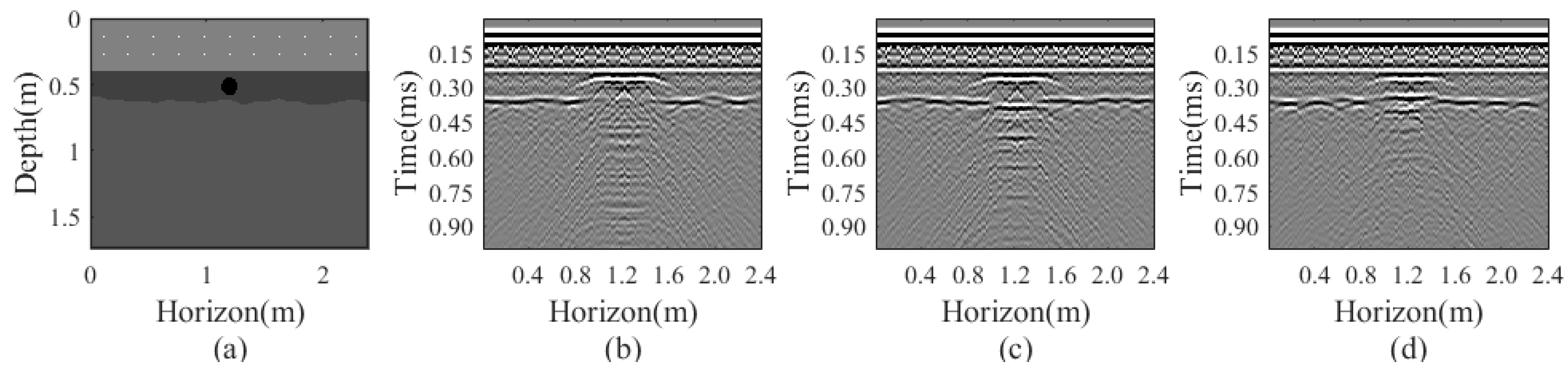
A numerical experiment (Figure 9a) is conducted to verify whether the elastic wave method can detect defects filled with air (Figure 9b), water (Figure 9c), and clay (Figure 9d). Compared with the GPR method, the seismic method can generate results when the defects are filled with air, water, and clay. The data are collected in the same manner as is done by GPR, thus comprising a common offset profile. The seismic method is more robust to changing defect fillings.
Compared with the GPR method, the elastic wave-based methods for detecting the grouting quality behind segment walls have better applicability in theory. (1) Elastic wave-based methods are better for consolidated grouting body detection because the consolidated grouting body and the surrounding soil still have a good elastic coefficient difference, and can thus produce obvious reflections. For the GPR method, many scholars suggest that the grouting body should be consolidated for a certain period (7–14 days) for better detection results [31,34,35]. (2) For detecting grouting bodies that have been consolidated, if the defect in the grouting layer is air filled, elastic wave methods have better detection results because the difference between the elastic parameters of the air and the grouting layer is greater than that of the dielectric. The interfaces can therefore produce better elastic wave reflection. (3) Compared with electromagnetic waves, the steel bars do not strongly interfere with the elastic waves, and the signals are not shielded by the steel bars. Elastic waves theoretically have better capabilities for detecting targets behind steel bars. (4) Elastic wave methods are limited by the survey efficiency because the coupling between sensors and concrete surfaces needs to be strong enough. Partially destructive contact or coupling agents are used in elastic wave surveys, thus resulting in the low feasibility of scanning surveys.
5.2. Transient Electromagnetic Method
The transient electromagnetic method (TEM) is based on the difference in the electrical resistivities of the underground layers used for hydrogeological purposes and general geological mapping [88,89].
Ye et al. [10,36] used both the GPR method and transient electromagnetic radar (TER) to detect grouting defects behind tunnel shield segments. A TER was designed based on the TEM, and was verified using TER to detect the grouting defects behind segments in a model test. Several resistivity change modes were summarized to distinguish the different contact states of the grouting layer behind the tunnel shield segments.
5.3. Summary
In this chapter, some GPR features in grouting defect detection are discussed. The GPR method has characteristics that are influenced by the tunnel shield segment structures, including steel bars, grouting layers, and grouting defects. In this chapter, we obtained the following. (1) The main interferences in detecting grouting defects behind tunnel shield segments come from the steel bars (including other metal objects) and multiple waves between the surface and segment interface. (2) The difference in the dielectric constants between materials determines the reflection amplitude. Thus, the defect fillings significantly influence the GPR detection results. (3) The configuration, coupling mode, and antenna frequencies affect grouting defect detection. (4) Other geophysical methods are promising for detecting grouting defects behind tunnel shield segments. The seismic method is the most theoretically adaptable because the elastic parameter differences are reliable for grouting defect detection. However, such seismic methods face an urgent need to solve sensor issues and rapid survey measures. (5) A comprehensive investigation will improve the efficiency and accuracy of grouting defect detection. For rapid surveying, air-coupled GPR is recommended. When a high-risk zone is found, ground-coupled GPR and seismic equipment can be used for high-resolution detection. The seismic method and TER can compensate for the deficiencies of the GPR method.
6. Discussion
In data acquisition, there are some advanced techniques that improve data information and effectively help tunnel shield construction. Many scholars indicate that multistep frequency can improve detection quality because different frequencies cause differences in penetration and attenuation. Generally, a higher frequency means a higher resolution but a smaller detection depth. In grouting defect detection, consolidation can cause a large difference in the dielectric constant of the grouting body. It is a unique characteristic in grouting defect detection, thus making the detection results very different after several weeks of injection. This characteristic can be used when the target objective is different. Additionally, grouting defect detection can instruct tunnel shield construction. The real-time GPR system was successfully applied in the tunnel shield machine to accordingly adjust the injection pressure and improve the grouting quality. According to the preliminary tests and reference [63], different antenna configurations can be used to support each other in the analysis. This is potentially a future research direction, but few studies are related to this aspect.
In signal processing, advanced techniques are used to improve the SNR, reconstruct the distribution of the subsurface, and determine grouting defects. In grouting defect detection, the interferences are intensive but with strong regularity. Most interferences include multiples and reflections of steel bars. In addition to regular processing, including defined gain and low-pass filtering, there are advanced methods to exclude artifacts and interferences. Predictive deconvolution, f-k multiple filtering, K-L transformation, and Maxwell’s curl equation can be used to eliminate the harmful effects and improve the SNR. By subtracting the predicted wave field of the designed segment structure, the reflection from the grouting layer and defects can be precisely abstract. For GPR profile imaging and reconstruction, most of the techniques used are seismic migration methods. Some new and advanced methods are emerging in GPR data processing; these methods include diffraction tomography, range migration, and BP methods. Data-based techniques, such as statistical and machine learning methods, are introduced into GPR processing. These methods can now be an assisting measure for traditional processing and might be a future research direction.
According to the advantages, characteristics, and limitations of each NDT method, it is concluded that other geophysical methods have potential. The elastic wave (acoustic) method is probably an available method for detecting grouting defects behind tunnel shield segments. Seismic geophysical theory has been well researched and widely used at various scales of investigation and exploration. In practice, elastic wave methods, including sonic, ultrasonic, and seismic methods, are widely used in the NDT of various concrete structures. In terms of the physical principle and the elastic parameter difference in the medium mentioned, the elastic wave method is a very suitable method for detecting grouting defects behind tunnel shield segments. However, there are still some limitations regarding the source coupling contact condition, sensor arrangement, and detection efficiency. Elastic wave detection equipment for detecting grouting defects behind tunnel shield segments is in urgent need of further research and development. Otherwise, grouting defect detection is large-scale work in real cases, and rapid investigation is urgently needed. For efficiency, an ideal investigation flow could be (1) using rapid detection methods to mark segments suspected of having a high risk of having defects and (2) using refined detection methods to locate defects and map subsurfaces. However, how to automatically determine the high-risk segments as quickly as possible is still unknown in field cases. This might also be a future research direction.
7. Conclusions
The GPR method has been proven to be a practical method for detecting grouting defects behind tunnel shield segments. In data acquisition, there are some advanced techniques that improve data information and effectively help tunnel shield construction. Advanced data acquisition techniques are used to obtain more information in different dimensions and capture different target objects. The detection performance of GPR is affected by factors such as antenna frequency, distance between transmission and reception, contact coupling conditions, and the curing of the grouting layer. For GPR profile interpretation and signal processing, scholars have proposed many effective methods to improve the SNR and profile image quality. Regular processing and advanced methods are used to exclude artifacts and interferences. Techniques from other scientific areas are emerging in GPR data processing; these techniques include diffraction tomography, range migration, and BP methods. Data-based techniques, such as statistical and machine learning methods, are introduced into GPR processing. However, thus far, the theoretical analysis, implementation, and signal processing of GPR still have deficiencies that limit GPR from being used for detecting grouting defects behind tunnel shield segments.
Additionally, other geophysical methods—especially elastic (acoustic) wave methods—can be considered for detecting grouting defects behind tunnel shield segments. Seismic geophysical theory has been well researched and widely used at various scales of investigation and exploration. In practice, elastic wave methods, including sonic, ultrasonic, and seismic methods, are widely used in the NDT of various concrete structures. However, efficient data acquisition in the elastic wave method could be an issue that needs to be solved.
Through an overview of detecting grouting defects behind tunnel shield segments by using GPR (and other NDT methods), further research should be carried out in the following directions:
(1) Study of various forms of GPR transmission and reception. Currently, GPR detection of grouting defects behind tunnel shield segments is carried out mostly with a constant transmitting and receiving distance. This form of transmission and reception somehow limits the information volume of the GPR signal to a certain extent. In the future, variable transmission and reception distances should be considered. A GPR array, in which multiple antennas simultaneously receive signals, should be used to enrich the information volume of the GPR signal.
(2) Research on rapid analysis methods for GPR data. In practice, detecting grouting defects behind tunnel shield segment walls involves a workload comprising several kilometers of tunnel construction with very many segments. Tunnel circumferential and axial inspections need to be performed at the same time, thus resulting in many GPR data. Therefore, the rapid analysis method of GPR defect recognition, which avoids manual interpretation, is a direction that needs to be studied.
(3) Refined FWI of the GPR profile. Currently, the GPR detection of grouting defects behind tunnel shield segments starts mostly with the common offset profile, and then a series of filtering, gaining, denoising and imaging processes are carried out to determine the location of the grouting defects. These processing methods can well characterize the positions of steel bars, grouting layer defects, and the grouting layer interface, but the defect types and media properties cannot be inverted. In the future, we should consider adopting FWI to further improve the GPR fine characterization ability in detecting grouting defects behind tunnel shield segments.
(4) Research on machine learning methods for GPR profiles and other NDT method data for detecting grouting defects behind tunnel shield segments. During NDT, the signal data generated have large volumes and variable dimensions; both of these characteristics are very suitable for analysis by using machine learning methods. Machine learning methods can be used for various purposes, such as data SNR improvement, feature extraction, and signal imaging. Therefore, the use of machine learning methods is a further research direction.
(5) Research on the transceiver arrangement of the elastic wave method, sensor coupling mode, and scanning detection equipment. The elastic wave method is very developed in studies on oil and gas exploration and engineering exploration, and the theoretical knowledge and practical experience are very rich. Moreover, the various media involved in detections of grouting defects behind tunnel shield segments have sufficient elastic parameter differences, thus indicating that such media are theoretically suitable for defect detection with the elastic wave method. On the one hand, to detect grouting defects behind tunnel shield segments, engineers need to complete much inspection work efficiently. However, on the other hand, the elastic wave method requires stable coupling between the sensor and the surface of the test object; this coupling is inconsistent with the required efficiency of the investigation. Therefore, research on elastic wave instruments and equipment, especially the excitation arrangement and sensor coupling mode, requires in-depth research.
(6) Research on the comprehensive detection of multiple NDT methods. When the grouting liquid is not completely solidified in the early stage of construction, it is difficult to carry out reliable detection by using GPR because of interference caused by the high conductivity of the media. However, the elastic wave method and the TER method can detect defects better when the grouting body is not completely solidified. Therefore, comprehensive detection and inversion with multiple geophysical methods is a way to improve detection reliability, and a direction that needs further research.
Author Contributions
Conceptualization, D.W.; funding acquisition, Z.S. and M.P.; methodology, L.L. and D.W.; project administration, M.P. and Z.S.; resources, M.P., L.L., Z.S. and F.M.; software, D.W., L.L. and J.S.; writing—original draft, D.W.; writing—review and editing, M.P., D.W. and L.L. All authors have read and agreed to the published version of the manuscript.
Funding
This research was funded by the National Natural Science Foundation of China, grant numbers 42172296, 42071010 and 42061160480, and the Shanghai Natural Science Foundation, grant number 20ZR1461300.
Data Availability Statement
The data presented in this study are available on request from the corresponding author.
Conflicts of Interest
The authors declare no conflict of interest.
References
- Armaghani, D.J.; Koopialipoor, M.; Marto, A.; Yagiz, S. Application of several optimization techniques for estimating TBM advance rate in granitic rocks. J. Rock Mech. Geotech. Eng. 2019, 11, 779–789. [Google Scholar] [CrossRef]
- Miliziano, S.; De Lillis, A. Predicted and observed settlements induced by the mechanized tunnel excavation of metro line C near S. Giovanni station in Rome. Tunn. Undergr. Space Technol. 2019, 86, 236–246. [Google Scholar] [CrossRef]
- Liu, X.X.; Shen, S.L.; Xu, Y.S.; Zhou, A. A diffusion model for backfill grout behind shield tunnel lining. Int. J. Numer. Anal. Methods Geomech. 2020, 45, 457–477. [Google Scholar] [CrossRef]
- Zhao, T.; Han, T.; Wu, G.; Gao, Y.; Lu, Y. Effects of grouting in reducing excessive tunnel lining deformation: Field experiment and numerical modelling using material point method. Tunn. Undergr. Space Technol. 2021, 116, 104114. [Google Scholar] [CrossRef]
- Wang, J.; Huang, H.; Xie, X.; Bobet, A. Void-induced liner deformation and stress redistribution. Tunn. Undergr. Space Technol. 2014, 40, 263–276. [Google Scholar] [CrossRef]
- Meguid, M.A.; Dang, H.K. The effect of erosion voids on existing tunnel linings. Tunn. Undergr. Space Technol. 2009, 24, 278–286. [Google Scholar] [CrossRef]
- Khazaei, S.; Shimada, H.; Kawai, T.; Yotsumoto, J.; Matsui, K. Monitoring of Over Cutting Area and Lubrication Distribution in a Large Slurry Pipe Jacking Operation. Geotech. Geol. Eng. 2006, 24, 735–755. [Google Scholar] [CrossRef]
- Torres-Luque, M.; Bastidas-Arteaga, E.; Schoefs, F.; Sánchez-Silva, M.; Osma, J.F. Non-destructive methods for measuring chloride ingress into concrete: State-of-the-art and future challenges. Constr. Build. Mater. 2014, 68, 68–81. [Google Scholar] [CrossRef] [Green Version]
- Tosti, F.; Ferrante, C. Using Ground Penetrating Radar Methods to Investigate Reinforced Concrete Structures. Surv. Geophys. 2020, 41, 485–530. [Google Scholar] [CrossRef]
- Ye, Z.J.; Zhang, C.P.; Ye, Y.; Zhu, W.J. Application of transient electromagnetic radar in quality evaluation of tunnel composite lining. Constr. Build. Mater. 2020, 240, 117958. [Google Scholar] [CrossRef]
- Solla, M.; Pérez-Gracia, V.; Fontul, S. A Review of GPR Application on Transport Infrastructures: Troubleshooting and Best Practices. Remote Sens. 2021, 13, 672. [Google Scholar] [CrossRef]
- Davis, J.L.; Annan, A.P. Ground-penetrating radar for high-resolution mapping of soil and rock stratigraphy1. Geophys. Prospect. 1989, 37, 531–551. [Google Scholar] [CrossRef]
- Annan, A.P. Chapter 1—Electromagnetic Principles of Ground Penetrating Radar. In Ground Penetrating Radar Theory and Applications; Jol, H.M., Ed.; Elsevier: Amsterdam, The Netherlands, 2009; pp. 1–40. [Google Scholar]
- Cassidy, N.J. Chapter 2—Electrical and Magnetic Properties of Rocks, Soils and Fluids. In Ground Penetrating Radar Theory and Applications; Jol, H.M., Ed.; Elsevier: Amsterdam, The Netherlands, 2009; pp. 41–72. [Google Scholar]
- Daniels, D.J. Chapter 4—Antennas. In Ground Penetrating Radar Theory and Applications; Jol, H.M., Ed.; Elsevier: Amsterdam, The Netherlands, 2009; pp. 99–139. [Google Scholar]
- Cassidy, N.J. Chapter 5—Ground Penetrating Radar Data Processing, Modelling and Analysis. In Ground Penetrating Radar Theory and Applications; Jol, H.M., Ed.; Elsevier: Amsterdam, The Netherlands, 2009; pp. 141–176. [Google Scholar]
- Carrick, U.E. Introduction. In Ground Penetrating Radar; Carrick, U.E., Ed.; Butterworth-Heinemann: Oxford, UK, 2017; pp. xiii–xvii. [Google Scholar]
- Carrick, U.E. Chapter 1—Fundamentals of GPR Operation. In Ground Penetrating Radar; Carrick, U.E., Ed.; Butterworth-Heinemann: Oxford, UK, 2017; pp. 1–11. [Google Scholar]
- Giannopoulos, A. Modelling ground penetrating radar by GprMax. Constr. Build. Mater. 2005, 19, 755–762. [Google Scholar] [CrossRef]
- Warren, C.; Giannopoulos, A.; Giannakis, I. gprMax: Open source software to simulate electromagnetic wave propagation for Ground Penetrating Radar. Comput. Phys. Commun. 2016, 209, 163–170. [Google Scholar] [CrossRef] [Green Version]
- Warren, C.; Giannopoulos, A.; Gray, A.; Giannakis, I.; Patterson, A.; Wetter, L.; Hamrah, A. A CUDA-based GPU engine for gprMax: Open source FDTD electromagnetic simulation software. Comput. Phys. Commun. 2019, 237, 208–218. [Google Scholar] [CrossRef]
- Zhao, Y.; Xie, X.; Wu, J.; Chen, J.; Ge, S. Maxwell curl equation datuming for GPR based on the Kirchhoff integral solution and application in a tunnel grouting test. Near Surf. Geophys. 2013, 11, 211–219. [Google Scholar] [CrossRef]
- Sun, F.; Wang, J.; Ma, C.; Li, W.; Zhang, F.; Fan, K. Cross-Hole Radar Fractures Detection of Tunnel Side Wall Based on Full Waveform Inversion and Reverse Time Migration. Geotech. Geol. Eng. 2021, 1–12. [Google Scholar] [CrossRef]
- Giannakis, I.; Giannopoulos, A.; Warren, C. Realistic FDTD GPR Antenna Models Optimized Using a Novel Linear/Nonlinear Full-Waveform Inversion. IEEE Trans. Geosci. Remote Sens. 2019, 57, 1768–1778. [Google Scholar] [CrossRef]
- Giannakis, I.; Giannopoulos, A.; Warren, C. A Machine Learning Scheme for Estimating the Diameter of Reinforcing Bars Using Ground Penetrating Radar. IEEE Geosci. Remote Sens. Lett. 2021, 18, 461–465. [Google Scholar] [CrossRef] [Green Version]
- Wai-Lok Lai, W.; Dérobert, X.; Annan, P. A review of Ground Penetrating Radar application in civil engineering: A 30-year journey from Locating and Testing to Imaging and Diagnosis. NDT E Int. 2018, 96, 58–78. [Google Scholar] [CrossRef]
- Bungey, J.H. Sub-surface radar testing of concrete: A review. Constr. Build. Mater. 2004, 18, 1–8. [Google Scholar] [CrossRef]
- Xie, X.; Liu, Y.; Huang, H.; Du, J.; Zhang, F.; Liu, L. Evaluation of grout behind the lining of shield tunnels using ground-penetrating radar in the Shanghai Metro Line, China. J. Geophys. Eng. 2007, 4, 253–261. [Google Scholar] [CrossRef]
- Zhang, F.; Xie, X.; Huang, H. Application of ground penetrating radar in grouting evaluation for shield tunnel construction. Tunn. Undergr. Space Technol. 2010, 25, 99–107. [Google Scholar] [CrossRef]
- Xie, X.; Zeng, C.; Wang, Z. GPR signal enhancement using band-pass and K–L filtering: A case study for the evaluation of grout in a shielded tunnel. J. Geophys. Eng. 2013, 10, 034003. [Google Scholar] [CrossRef]
- Yu, Q.-M.; Zhou, H.-L.; Wang, Y.-H.; Duan, R.-X. Quality monitoring of metro grouting behind segment using ground penetrating radar. Constr. Build. Mater. 2016, 110, 189–200. [Google Scholar] [CrossRef]
- Zhao, Y.; Wu, J.; Xie, X.; Feng, K.; Zeng, C. Ground-penetrating radar measurement of the distribution of thixotropic slurry behind large-diameter segments in long-distance pipe-jacking construction. Near Surf. Geophys. 2016, 14, 171–181. [Google Scholar] [CrossRef]
- Lalagüe, A.; Lebens, M.A.; Hoff, I.; Grøv, E. Detection of Rockfall on a Tunnel Concrete Lining with Ground-Penetrating Radar (GPR). Rock Mech. Rock Eng. 2016, 49, 2811–2823. [Google Scholar] [CrossRef]
- Hu, S.; Xu, G.; Tang, F.; Ma, F.; Rong, J. Optimization Research on GPR Detecting of Grouting behind Shield Tunnel S in Water-Soaked Sand and Pebble Stratum. In Proceedings of the 2016 International Conference on Intelligent Transportation, Big Data & Smart City (ICITBS), Changsha, China, 17–18 December 2016. [Google Scholar]
- Kravitz, B.; Mooney, M.; Karlovsek, J.; Danielson, I.; Hedayat, A. Void detection in two-component annulus grout behind a pre-cast segmental tunnel liner using Ground Penetrating Radar. Tunn. Undergr. Space Technol. 2019, 83, 381–392. [Google Scholar] [CrossRef]
- Ye, Z.; Ye, Y. Comparison of Detection Effect of Cavities Behind Shield Tunnel Segment Using Transient Electromagnetic Radar and Ground Penetration Radar. Geotech. Geol. Eng. 2019, 37, 4391–4403. [Google Scholar] [CrossRef]
- Zeng, L.; Zhou, B.; Xie, X.; Zhao, Y.; Liu, H.; Zhang, Y.; Shahrour, I. A novel real-time monitoring system for the measurement of the annular grout thickness during simultaneous backfill grouting. Tunn. Undergr. Space Technol. 2020, 105, 103567. [Google Scholar] [CrossRef]
- Xie, X.; Zhai, J.; Zhou, B. Back-fill grouting quality evaluation of the shield tunnel using ground penetrating radar with bi-frequency back projection method. Autom. Constr. 2021, 121, 103435. [Google Scholar] [CrossRef]
- Qin, H.; Tang, Y.; Wang, Z.; Xie, X.; Zhang, D. Shield tunnel grouting layer estimation using sliding window probabilistic inversion of GPR data. Tunn. Undergr. Space Technol. 2021, 112, 103913. [Google Scholar] [CrossRef]
- Xiang, L.; Zhou, H.-L.; Shu, Z.; Tan, S.-H.; Liang, G.-Q.; Zhu, J. GPR evaluation of the Damaoshan highway tunnel: A case study. NDT E Int. 2013, 59, 68–76. [Google Scholar] [CrossRef]
- Hong, W.-T.; Kang, S.; Lee, S.J.; Lee, J.-S. Analyses of GPR signals for characterization of ground conditions in urban areas. J. Appl. Geophys. 2018, 152, 65–76. [Google Scholar] [CrossRef]
- Zhao, Y.; Wu, J.; Xie, X.; Chen, J.; Ge, S. Multiple Suppression in GPR Image for Testing Back-Filled Grouting within Shield Tunnel. In Proceedings of the XIII Internarional Conference on Ground Penetrating Radar, Lecce, Italy, 21–25 June 2010. [Google Scholar]
- Luo, T.X.H.; Lai, W.W.L.; Chang, R.K.W.; Goodman, D. GPR imaging criteria. J. Appl. Geophys. 2019, 165, 37–48. [Google Scholar] [CrossRef]
- Garambois, S.; Sénéchal, P.; Perroud, H. On the use of combined geophysical methods to assess water content and water conductivity of near-surface formations. J. Hydrol. 2002, 259, 32–48. [Google Scholar] [CrossRef]
- Huisman, J.A.; Sperl, C.; Bouten, W.; Verstraten, J.M. Soil water content measurements at different scales: Accuracy of time domain reflectometry and ground-penetrating radar. J. Hydrol. 2001, 245, 48–58. [Google Scholar] [CrossRef]
- Zajícová, K.; Chuman, T. Application of ground penetrating radar methods in soil studies: A review. Geoderma 2019, 343, 116–129. [Google Scholar] [CrossRef]
- Berryhill, J.R. Wave-equation datuming before stack. Geophysics 1984, 49, 2064. [Google Scholar] [CrossRef]
- Berryhill, J.R. Wave-equation datuming. Geophysics 1979, 44, 1329. [Google Scholar] [CrossRef]
- Reshef, M. Depth migration from irregular surfaces with depth extrapolation methods. Geophysics 1991, 56, 119. [Google Scholar] [CrossRef]
- McMechan, G. Implicit static corrections in prestack migration of common-source data. Geophysics 1990, 55, 757–760. [Google Scholar] [CrossRef] [Green Version]
- Grasmueck, M.; Weger, R.; Horstmeyer, H. Full-resolution 3D GPR imaging. Geophysics 2005, 70, K12–K19. [Google Scholar] [CrossRef]
- Grasmueck, M. 3-D ground-penetrating radar applied to fracture imaging in gneiss. Geophysics 1996, 61, 1050–1064. [Google Scholar] [CrossRef]
- Krauze, W.; Kuś, A.; Śladowski, D.; Skrzypek, E.; Kujawińska, M. Reconstruction method for extended depth-of-field optical diffraction tomography. Methods 2018, 136, 40–49. [Google Scholar] [CrossRef] [PubMed]
- Kodjikian, S.; Klein, H. Low-dose electron diffraction tomography (LD-EDT). Ultramicroscopy 2019, 200, 12–19. [Google Scholar] [CrossRef] [PubMed]
- Leandro, C.G.; Barboza, E.G.; Caron, F.; De Jesus, F.A.N. GPR trace analysis for coastal depositional environments of southern Brazil. J. Appl. Geophys. 2019, 162, 1–12. [Google Scholar] [CrossRef]
- Demirci, S.; Yigit, E.; Eskidemir, I.H.; Ozdemir, C. Ground penetrating radar imaging of water leaks from buried pipes based on back-projection method. NDT E Int. 2012, 47, 35–42. [Google Scholar] [CrossRef]
- Schofield, R.; King, L.; Tayal, U.; Castellano, I.; Stirrup, J.; Pontana, F.; Earls, J.; Nicol, E. Image reconstruction: Part 1—Understanding filtered back projection, noise and image acquisition. J. Cardiovasc. Comput. Tomogr. 2020, 14, 219–225. [Google Scholar] [CrossRef]
- Lavoué, F.; Brossier, R.; Métivier, L.; Garambois, S.; Virieux, J. Two-dimensional permittivity and conductivity imaging by full waveform inversion of multioffset GPR data: A frequency-domain quasi-Newton approach. Geophys. J. Int. 2014, 197, 248–268. [Google Scholar] [CrossRef] [Green Version]
- Giannakis, I.; Giannopoulos, A.; Warren, C. A Machine Learning-Based Fast-Forward Solver for Ground Penetrating Radar with Application to Full-Waveform Inversion. IEEE Trans. Geosci. Remote Sens. 2019, 57, 4417–4426. [Google Scholar] [CrossRef] [Green Version]
- Yang, X.; Klotzsche, A.; Meles, G.; Vereecken, H.; van der Kruk, J. Improvements in crosshole GPR full-waveform inversion and application on data measured at the Boise Hydrogeophysics Research Site. J. Appl. Geophys. 2013, 99, 114–124. [Google Scholar] [CrossRef]
- Minet, J.; Bogaert, P.; Vanclooster, M.; Lambot, S. Validation of ground penetrating radar full-waveform inversion for field scale soil moisture mapping. J. Hydrol. 2012, 424–425, 112–123. [Google Scholar] [CrossRef] [Green Version]
- Eisenmann, D.; Margetan, F.; Chiou, C.-P.T.; Roberts, R.; Wendt, S. Ground penetrating radar applied to rebar corrosion inspection. AIP Conf. Proc. 2013, 1511, 1341–1348. [Google Scholar]
- Forte, E.; Pipan, M. Review of multi-offset GPR applications: Data acquisition, processing and analysis. Signal Process. 2017, 132, 210–220. [Google Scholar] [CrossRef]
- Tsoflias, G.P.; Perll, C.; Baker, M.; Becker, M.W. Cross-polarized GPR imaging of fracture flow channeling. J. Earth Sci. 2015, 26, 776–784. [Google Scholar] [CrossRef]
- Gagarin, N.; Mekemson, J. Step-frequency ground-penetrating-radar array calibration requirements to estimate dielectric properties of pavements. Near Surf. Geophys. 2016, 14, 105–115. [Google Scholar] [CrossRef]
- Yilmaz, O. Seismic Data Analysis: Processing, Inversion, and Interpretation of Seismic Data; SEG: Tulsa, OK, USA, 2001. [Google Scholar]
- Asl, B.M.; Mahloojifar, A. Minimum Variance Beamforming Combined with Adaptive Coherence Weighting Applied to Medical Ultrasound Imaging. IEEE Trans. Ultrason. Ferroelectr. Freq. Control 2009, 56, 1923–1931. [Google Scholar] [CrossRef] [PubMed]
- Havlice, J.F.; Taenzer, J.C. Medical ultrasonic imaging: An overview of principles and instrumentation. Proc. IEEE 1979, 67, 620–641. [Google Scholar] [CrossRef]
- Synnevag, J.F.; Austeng, A.; Holm, S. Adaptive Beamforming Applied to Medical Ultrasound Imaging. IEEE Trans. Ultrason. Ferroelectr. Freq. Control 2007, 54, 1606–1613. [Google Scholar] [CrossRef] [PubMed] [Green Version]
- Lambot, S.; Weihermüller, L.; Huisman, J.A.; Vereecken, H.; Vanclooster, M.; Slob, E.C. Analysis of air-launched ground-penetrating radar techniques to measure the soil surface water content. Water Resour. Res. 2006, 42, 11. [Google Scholar] [CrossRef] [Green Version]
- Zan, Y.; Li, Z.; Su, G.; Zhang, X. An innovative vehicle-mounted GPR technique for fast and efficient monitoring of tunnel lining structural conditions. Case Stud. Nondestruct. Test. Eval. 2016, 6, 63–69. [Google Scholar] [CrossRef] [Green Version]
- Leng, Z.; Al-Qadi, I.L. An innovative method for measuring pavement dielectric constant using the extended CMP method with two air-coupled GPR systems. NDT E Int. 2014, 66, 90–98. [Google Scholar] [CrossRef]
- Terzioglu, T.; Karthik, M.M.; Hurlebaus, S.; Hueste, M.B.D.; Maack, S.; Woestmann, J.; Wiggenhauser, H.; Krause, M.; Miller, P.K.; Olson, L.D. Nondestructive evaluation of grout defects in internal tendons of post-tensioned girders. NDT E Int. 2018, 99, 23–35. [Google Scholar] [CrossRef]
- Wimsatt, A.; White, J.; Leung, C.; Scullion, T.; Hurlebaus, S.; Zollinger, D.; Grasley, Z.; Nazarian, S.; Azari, H.; Yuan, D. Mapping Voids, Debonding, Delaminations, Moisture, and Other Defects behind or within Tunnel Linings; The National Academies Press: Washington, DC, USA, 2014. [Google Scholar]
- Wang, X.; Meng, L.; Cheng, D.; Lu, S. Research and Application of Comprehensive Geophysical Methods for Quality Testing of Backfill Grouting behind Lining Segment of TBM Construction Tunnel (in Chinese). Tunn. Constr. 2019, 39, 166–175. [Google Scholar]
- Wang, H.; Che, A.; Feng, S. Quantitative Investigation on Grouting Quality of Immersed Tube Tunnel Foundation Base using Full Waveform Inversion Method. Geotech. Test. J. 2017, 40, 833–845. [Google Scholar] [CrossRef]
- Tang, H.-X.; Long, S.-G.; Li, T. Quantitative evaluation of tunnel lining voids by acoustic spectrum analysis. Constr. Build. Mater. 2019, 228, 116762. [Google Scholar] [CrossRef]
- Sansalone, M.; Lin, Y. Detecting Delaminations in Concrete Slabs with or without Overlays Using the Impact Echo Method. Springer Neth. 1991, 86, 175–184. [Google Scholar]
- Sansalone, M. Detecting Delaminations in Concrete Bridge Decks with and Without Asphalt Overlays Using an Automated Impact-Echo Field System. In Proceedings of the Conference British Institute of Non-destructive Testing International Conference, Liverpool, UK, 14–16 April 1993. [Google Scholar]
- Carino, N.J. The impact-echo method: An overview. In Proceedings of the Structures Structures Congress, Washington, DC, USA, 21–23 May 2001. [Google Scholar]
- Colla, C. Improving the Accuracy of Impact-Echo in Testing Post-Tensioning Ducts. AIP Conf. Proc. 2003, 657, 1185–1192. [Google Scholar]
- Yao, F.; Chen, G.; Su, J. Experimental Research and Numerical Simulation on Grouting Quality of Shield Tunnel Based on Impact Echo Method. Shock Vib. 2016, 2016, 1025276. [Google Scholar] [CrossRef] [Green Version]
- Wang, J.-J.; Chang, T.-P.; Chen, B.-T.; Lin, H.-C.; Wang, H. Evaluation of Resonant Frequencies of Solid Circular Rods with Impact-Echo Method. J. Nondestruct. Eval. 2010, 29, 111–121. [Google Scholar] [CrossRef]
- Lee, I.; Kwon, S.-H.; Park, J.; Oh, T. The effective near-surface defect identification by dynamic behavior associated with both impact-echo and flexural modes for concrete structures. KSCE J. Civ. Eng. 2018, 22, 747–754. [Google Scholar] [CrossRef]
- Kim, D.S.; Seo, W.S.; Lee, K.M. IE–SASW method for nondestructive evaluation of concrete structure. NDT E Int. 2006, 39, 143–154. [Google Scholar] [CrossRef]
- Yao, F.; Chen, G.; Abula, A. Research on signal processing of segment-grout defect in tunnel based on impact-echo method. Constr. Build. Mater. 2018, 187, 280–289. [Google Scholar] [CrossRef]
- Yao, F.; Chen, G. Time-Frequency Analysis of Impact Echo Signals of Grouting Defects in Tunnels. Russ. J. Nondestruct. Test. 2019, 55, 581–595. [Google Scholar] [CrossRef]
- Zhang, D.; Yang, H.; Rao, Z.; Ou, Z.; Tang, P. Research on Application of Transient Electromagnetic Method in Hydraulic Fracturing. Geotech. Geol. Eng. 2019, 38, 507–516. [Google Scholar] [CrossRef]
- Wu, G.; Yang, G.; Tan, H. Mapping coalmine goaf using transient electromagnetic method and high density resistivity method in Ordos City, China. Geod. Geodyn. 2016, 7, 340–347. [Google Scholar] [CrossRef] [Green Version]
Figure 1.
Cross-section profile of a shield tunnel segment.

Figure 2.
(a) Conceptual illustration of GPR use in defect detection by using a ground-coupled antenna system; (b) A-scan amplitude; (c) A synthetic B-scan profile for segment inspection.
Figure 2.
(a) Conceptual illustration of GPR use in defect detection by using a ground-coupled antenna system; (b) A-scan amplitude; (c) A synthetic B-scan profile for segment inspection.

Figure 3.
The full-size test model. (a) Full-size experimental segment model; (b) Six segments in the model; (c) A flattened illustration of the segment model with grouting defects.
Figure 3.
The full-size test model. (a) Full-size experimental segment model; (b) Six segments in the model; (c) A flattened illustration of the segment model with grouting defects.

Figure 4.
Test results for different filling materials. (a) Defects filled with air; (b) Defects filled with water.
Figure 4.
Test results for different filling materials. (a) Defects filled with air; (b) Defects filled with water.

Figure 5.
Plan view of the different possible transmitter-receiver configurations. (a) Directions of electric vector and magnetic vector in an antenna; (b) End fire TM mode; (c) Broadside TM mode; (d) Cross-polarized TM mode; (e) End fire TE mode; (f) Broadside TE mode; (g) Cross-polarized TE mode.
Figure 5.
Plan view of the different possible transmitter-receiver configurations. (a) Directions of electric vector and magnetic vector in an antenna; (b) End fire TM mode; (c) Broadside TM mode; (d) Cross-polarized TM mode; (e) End fire TE mode; (f) Broadside TE mode; (g) Cross-polarized TE mode.

Figure 6.
Test results of different transmitter-receiver configurations. (a) Electric field vector oscillating along the survey direction; (b) Electric field vector oscillating perpendicular to the survey direction.
Figure 6.
Test results of different transmitter-receiver configurations. (a) Electric field vector oscillating along the survey direction; (b) Electric field vector oscillating perpendicular to the survey direction.

Figure 7.
A beamformer illustration.

Figure 8.
Test results for different antenna frequencies: (a) 400 MHz and (b) 900 MHz.

Figure 9.
Synthetic seismic detection of (a) grouting defects filled with (b) air, (c) water, and (d) clay.
Figure 9.
Synthetic seismic detection of (a) grouting defects filled with (b) air, (c) water, and (d) clay.


Table 1.
Some examples of GPR applications on tunnel liners and grouting.
| Reference | Frequency | Survey Line Direction | Location | Tunnel Type | Detection Object | 3D | Main Results and Conclusions |
|---|---|---|---|---|---|---|---|
| Xie et al., 2007 [28] | 200 MHz | Axial | Shanghai, China | Metro | Grout quality and defects | No | The GPR is an effective method to detect the quality of the grouting after the pipe segment. The 200 MHz antenna meets the requirements of detection and detection depth at the same time. |
| Zhang et al., 2010 [29] | 250 MHz, 500 MHz, 1 GHz | Hoop | Shanghai, China | Metro | Grouting layer thickness | No | The most reliable frequency is 500 MHz. The detection quality is further improved when the grouting layer is consolidated. The dielectric parameters of the tested materials are pretested in the laboratory, thus helping to improve detection quality. |
| Zhao et al., 2013 [22] | 1000 MHz | Hoop | Shanghai, China | Metro | Interface between the grouting layer and surrounding rock | No | The imaging method based on Maxwell’s curl equation is proposed; the proposed method effectively suppresses the strong scattering caused by steel bars and amplifies the reflection signal of the interface between the grouting layer and the soil. |
| Xie et al., 2013 [30] | 500 MHz | Axial | Shanghai, China | Transport tunnel | Grouting layer thickness | No | The signal-to-noise ratio is improved by using bandpass and K-L filtering. |
| Yu et al., 2016 [31] | 800 MHz | Axial and hoop | Nanchang, China | Metro | Grout layer thickness and existence of defects | No | The thickness of the grouting layer and grouting defects are detected. Suggestions for supplementary grouting are given based on the detection results. |
| Zhao et al., 2016 [32] | 900 MHz | Hoop | Shanghai, China | Port transportation tunnel | Grout quality and defects | No | The quality of the radar image is improved, and the interface between the grouting layer and the rock-soil is effectively detected, thus further helping to determine the grouting quality. |
| Lalague et al., 2016 [33] | 100 MHz | Axial and hoop | Vestfold, Norway | Highway tunnel | The gap between the tunnel lining and the surrounding rock | Yes | The detection of the tunnel roof rocks falling onto the concrete segments is realized, and the antenna frequency and layout suggestions are given for different scenes and stone sizes. |
| Hu et al., 2016 [34] | 200 MHz, 400 MHz | Hoop | Nanning, China | Full-size tunnel shield model | Preset defects in grouting layer | No | China’s first full-scale preset defect shield tunnel segment grouting inspection experimental platform is presented. It is pointed out that the seventh day after grouting is the best time to inspect the quality of grouting behind the wall, and a reasonable distance between the transmitting and receiving antennas is the key to good detection. |
| Kravitz et al., 2019 [35] | 400 MHz, 800 MHz, 900 MHz, 1200 MHz, 1600 MHz, 2600 MHz | Hoop | Colorado, United States | Tunnel shield model | Preset air/saturated defect | No | Considering different frequencies, it is determined that a 900 MHz frequency antenna can penetrate the steel bar while maintaining the highest resolution. Due to the high conductivity of the slurry, it is difficult to detect the curve of the grouting body when the curing time is insufficient. |
| Ye et al., 2019 [36] | 900 MHz | Axial | Beijing, China | Tunnel shield model | Anomalies behind the segment | No | Comparing the GPR method and the TER method shows that TER detection can compensate the shortcomings of GPR detection. |
| Zeng et al., 2020 [37] | 300 MHz | Axial | Shanghai, China | Metro | Grout quality | Yes | A real-time GPR detection system for controlling the quality of grouting behind tunnel shield segments is established. |
| Xie et al., 2021 [38] | 400 MHz, 900 MHz | Axial | Jinan, China | Metro | Grouting layer boundary and defects | No | The BBP method is introduced for detecting the grouting defects behind the tunnel shield segment. |
| Qin et al., 2021 [39] | 900 MHz | Hoop | – | Numerical model | Grouting layer thickness, relative permittivity, and conductivity values | No | The sliding window and Markov chain Monte Carlo with Bayesian inference are introduced to explore the posterior distribution of the model parameters. |
Table 2.
Summary of GPR measurements recommendation under certain situation according to [33].
Table 2.
Summary of GPR measurements recommendation under certain situation according to [33].
| GPR System | Ground-Coupled | Air-Coupled | Step-Frequency | |||
|---|---|---|---|---|---|---|
| Frequency | 400 MHz | 1.5 GHz | 2.6 GHz | 1 GHz | 2 GHz | 100 MHz–3 GHz |
| Large rocks | No | Yes | No | Yes | No | Yes |
| Small and medium-sized rocks | No | Yes | Yes | No | No | Yes |
Table 3.
GPR antenna frequency range and application according to [26].
Table 3.
GPR antenna frequency range and application according to [26].
| GPR Frequency | Application |
|---|---|
| 10–100 MHz | Foundation inspection in depths of tens of meters. |
| 100–1000 MHz | Pavement and tunnel lining investigation within a few meters. |
| 1000–5000 MHz | Tunnel lining and structure investigation at a centimeter scale. |
Table 4.
The main NDT methods for the investigation of concrete and reinforced concrete materials and structures according to [9,11,33].
| Method | Contact Mode | Applications | Advantages | Limitations |
|---|---|---|---|---|
| Sonic | Contact and partially destructive | Defects detection and uniformity evaluation. Structure strength evaluation. | Reliability of results. Suitability for outdoor surveys. | Complexity of result interpretation. High signal attenuation for high-resolution imaging. Low- efficient data acquisition. Stable coupling required. |
| Ultrasonic | Contact and partially destructive | Defects detection and uniformity evaluation. | Reliability of results. Portable equipment is available. Relatively easy to use. | Applicable to limited member thickness. Experienced operators required. Stable coupling required. |
| Microwave | Noncontact and fully nondestructive | Evaluation of concrete decay conditions. Moisture distribution evaluation. | Small size of the antennas. High-resolution. | Available hardwires are not suitable for outdoor surveys. Difficulty in identifying the nature of the decay. |
| Infrared Thermography | Noncontact Fully nondestructive | Voids and delamination detection. Defect evaluation. Assessment of concrete moisture conditions. | Reliability of the result. Suitability for the rapid assessment of large or high- rise buildings. Remote use without direct coupling with the structures/materials. | Limitations for deep defects. Difficulty in decay detection for low-quality concrete. Expensive equipment. Experienced operator required. |
| GPR | Contact/noncontact and fully nondestructive | Defect and decay detection. Location of rebars. Estimation of rebar size. Measurement of dielectric properties. Industrial quality control. | Totally nondestructive. Portable equipment. Use of different frequencies for different types of targets. Real-time continuous display of collected results. Rapid investigations of large areas. Sensitive to the presence of moisture and chlorides. | Skill required to interpret the data. Congested reinforcement can prevent penetration beyond the reinforcement. Difficulty in detecting early-stage decay. Cracks and delamination not easy to detect unless moisture is present in the cracks or in the region of the delamination. Limited penetration depth of the pulses from high-resolution antennas (300 to 500 mm). |
| Radiography | Contact and fully nondestructive | Visualizing the internal structure of the test object. Use of image plates to extract more information about the internal structure of the test object. Checking the reinforced bars. | Equipment can be turned off when not in use (X-rays). Equipment reasonably portable and cost-effective (γ-rays). Minimal operator skills required for data collection (γ-rays). Reliability of results for large data sets. | Safety concerns due to the emission of hazardous radiations. Operators must be licensed. Bulky and expensive equipment (X-rays). γ-ray penetration limited to 500 mm in concrete materials. Access to opposing faces required. Large differences more readily detected than small differences. Difficulty in identifying cracks perpendicular to the radiation beam. |
Publisher’s Note: MDPI stays neutral with regard to jurisdictional claims in published maps and institutional affiliations. |
© 2021 by the authors. Licensee MDPI, Basel, Switzerland. This article is an open access article distributed under the terms and conditions of the Creative Commons Attribution (CC BY) license (https://creativecommons.org/licenses/by/4.0/).
Share and Cite
MDPI and ACS Style
Peng, M.; Wang, D.; Liu, L.; Shi, Z.; Shen, J.; Ma, F. Recent Advances in the GPR Detection of Grouting Defects behind Shield Tunnel Segments. Remote Sens. 2021, 13, 4596. https://0-doi-org.brum.beds.ac.uk/10.3390/rs13224596
AMA Style
Peng M, Wang D, Liu L, Shi Z, Shen J, Ma F. Recent Advances in the GPR Detection of Grouting Defects behind Shield Tunnel Segments. Remote Sensing. 2021; 13(22):4596. https://0-doi-org.brum.beds.ac.uk/10.3390/rs13224596
Chicago/Turabian StylePeng, Ming, Dengyi Wang, Liu Liu, Zhenming Shi, Jian Shen, and Fuan Ma. 2021. "Recent Advances in the GPR Detection of Grouting Defects behind Shield Tunnel Segments" Remote Sensing 13, no. 22: 4596. https://0-doi-org.brum.beds.ac.uk/10.3390/rs13224596
Note that from the first issue of 2016, this journal uses article numbers instead of page numbers. See further details here.