1. Introduction
The miniaturization of antennas for global navigation satellite system (GNSS) receivers is important to meeting the requirements of customers for more compact devices. If an antenna has overall dimensions (including any ground plane) of less than one-quarter of a wavelength (λ/4), it is often referred to as an electrically small antenna (ESA) [
1]. The theoretical gain and bandwidth of an ESA is limited by its size [
2,
3,
4,
5]. In general, the miniaturization of an antenna leads to low radiation resistance, high input reactance, a narrow impedance bandwidth, and poor radiation efficiency. Therefore, it is somewhat difficult to design an ESA with a frequency range covering the full band of GNSS signals.
The main miniaturization techniques—antenna loading (by using high-permittivity or high-permeability materials), virtualization of some parts of the antenna (by using ground planes or short circuits), and optimization of the geometry—can be employed to design ESAs. By using at least two of the abovementioned miniaturizing techniques, one can expect better performance of ESAs. Various ESA designs employing different miniaturization techniques have been reported in the literature. For example, in [
6], a monopole with a height of approximately 0.16 λ was top-loaded to cover a frequency range from 1750 to 2500 MHz, and in [
7], high-permittivity materials (between 10 and 100) were investigated to shorten a rectangular dielectric resonator antenna. In [
8], a short-circuited monopole antenna, which is partially similar to the design proposed in this letter, was presented. The authors noted that apart from the normal omnidirectional radiation in the plane perpendicular to the monopole antenna, some radiation was observed in a plane in the transverse direction of the antenna and parallel to the axis of the monopole. This is probably because the antenna extended in the longitudinal direction; thus, the surface current flow was more intensive in the lateral direction, which, in turn, changed the principal polarization of the antenna.
This paper is an extended version of [
9], where the design of an ESA for BeiDou GNSSs is presented. The design is based on antenna loading, ground plane imaging, and optimization of the matching circuit geometry. The novel contribution of this letter in respect to [
9] includes a new method of tuning to bands of different GNSSs. In addition, the operational principle and analysis of the radiation characteristic are meticulously discussed.
2. Materials and Methods
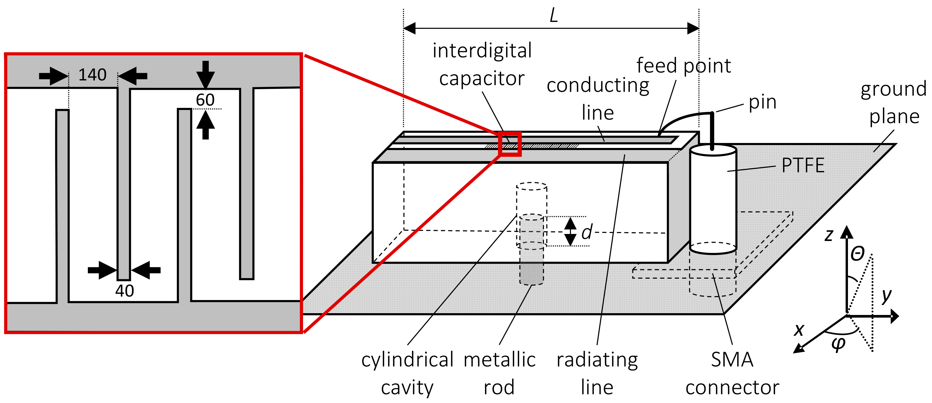
The main concept of the proposed ESA, which is shown in
Figure 1, is based on antenna loading by using a dielectric block (22 × 10 × 10 mm) and utilizing a ground plane. A 7-mm-long cylindrical cavity was drilled inside the dielectric block, and a metallic rod was inserted into this cavity for frequency tuning of the ESA. The dielectric block was made of sapphire and was placed on a 30 × 30 mm ground plane. The value of the sapphire permittivity used for the simulations and optimization was measured in our laboratory and found to equal 11.2, which corresponds well with the literature [
10]. The characterization of sapphire was performed by using a very precise split post-dielectric resonator technique [
11]. A surface of the dielectric block adjacent to the connector was fully coated by a conductive material. This surface, together with a conductive layer placed on the top surface, formed the radiating line. The other line, named the conducting line, was also located on the top surface. An interdigital capacitor was placed between the conducting line and the radiating line and interconnected both. The interdigital capacitor was composed of 40-μm-thick parallel lines 180 μm apart, as illustrated in
Figure 1. The lines alternatively connected the conducting line and the radiating line. The ESA was fed by a coaxial connector, SubMiniature version A (SMA), with a long central pin approximately 0.05 λ in length, where λ is the free-space wavelength. The length of the pin was 5 times smaller than the typical length of a quarter-wavelength monopole antenna for the L-band. The pin was connected to the conducting line on the top surface and was loaded by an interdigital capacitor. The capacitance of the interdigital capacitor has a crucial impact on antenna performance; therefore, its dimensions were optimized considering both the permittivity and dimensions of the dielectric block.
The design of the ESA presented in this communication somewhat resembles the inverted-F antenna (IFA) and inverted-L antenna (ILA) illustrated in
Figure 2a,b, respectively. However, a closer look reveals a significant difference—for both IFA and ILA, the radiation in the direction indicated by the arrows in
Figure 2a,b is noticeably reduced, and the polarization of both antennas is linear and oriented toward the electric field vector E.
The ILA is a type of a top-loaded monopole. For such a structure, the surface current density is significant only in the direction that is perpendicular to the ground plane. Moreover, at the feed point of the monopole, the current density is the highest. The current distribution is almost uniform because the top-loading helps to equalize it. In the top-loaded monopole, increasing the current generates incremental radiation resistance and input impedance.
The IFA also has no longitudinal current component due to the proximity of the longitudinal part of the antenna to the ground plane. In this case, the existence of a longitudinal current is limited.
Conversely, the proposed ESA demonstrated a significant density of surface currents, not only on the parts perpendicular to the ground plane (as is the case for a monopole), but also on the parallelly oriented parts, as illustrated in
Figure 2c. This is confirmed by the results of the surface current simulation shown in
Figure 2d. Such a unique feature enables radiation along the
z-axis.
To obtain an effective radiating structure, the currents have to add up in phase. Moreover, the impedance of the transmission line should match the input impedance of the antenna.
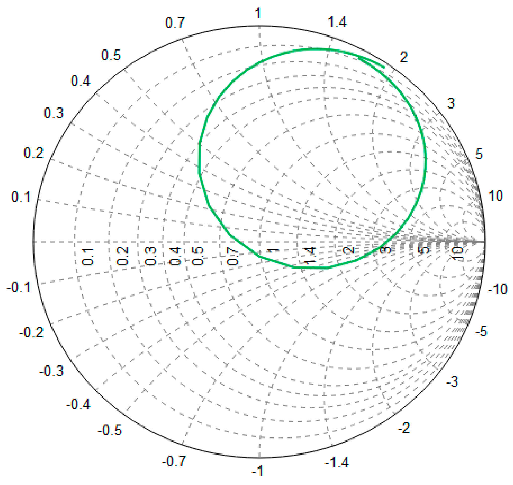
In our antenna, the feed “sees” a conducting line that is a fraction of a wavelength and that is connected to a radiating line with an interdigital capacitor. The radiating line consists of an open circuit on the one side of the interdigital capacitor and is connected to the ground plane on the other side according to
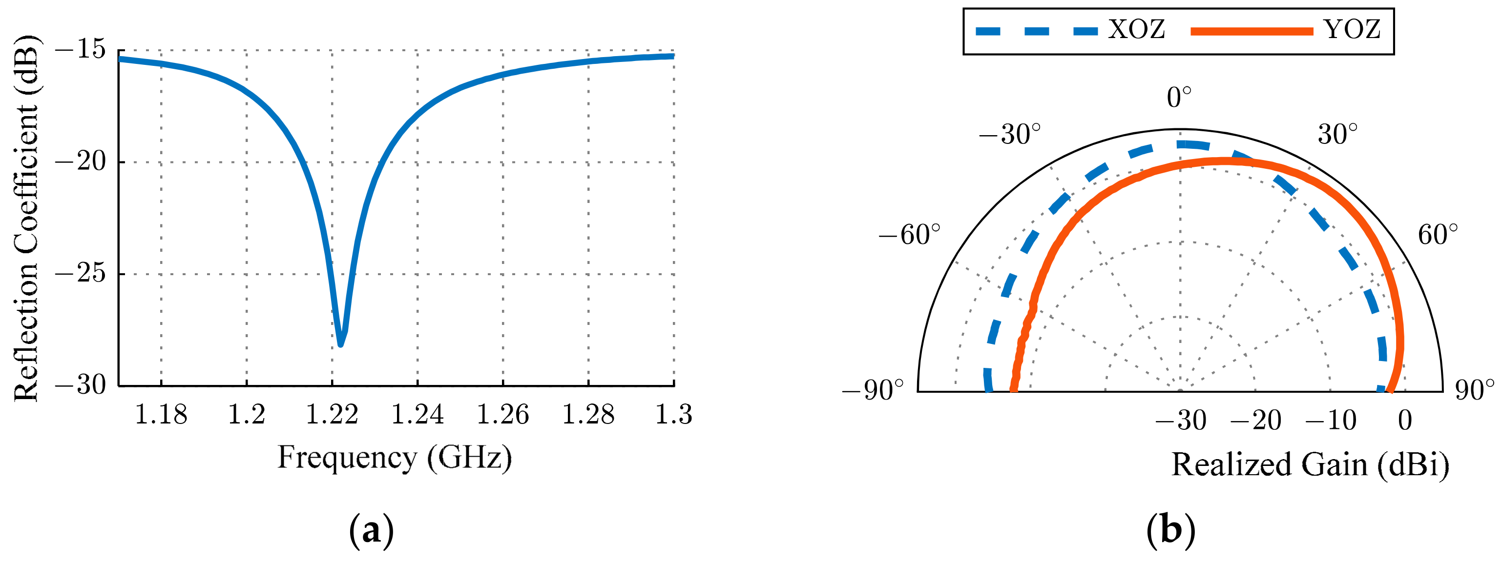
Figure 2c. The feed location was chosen to "balance out" the capacitance and the inductance of such a structure. The inductance and capacitance canceled out one another, leaving just the radiation resistance and the resistance related to the losses. The complex reflection coefficient is shown in
Figure 3. Its value is close to 1, obtained for a frequency of 1232 MHz and a 5-mm-long metallic rod inserted into the dielectric block.
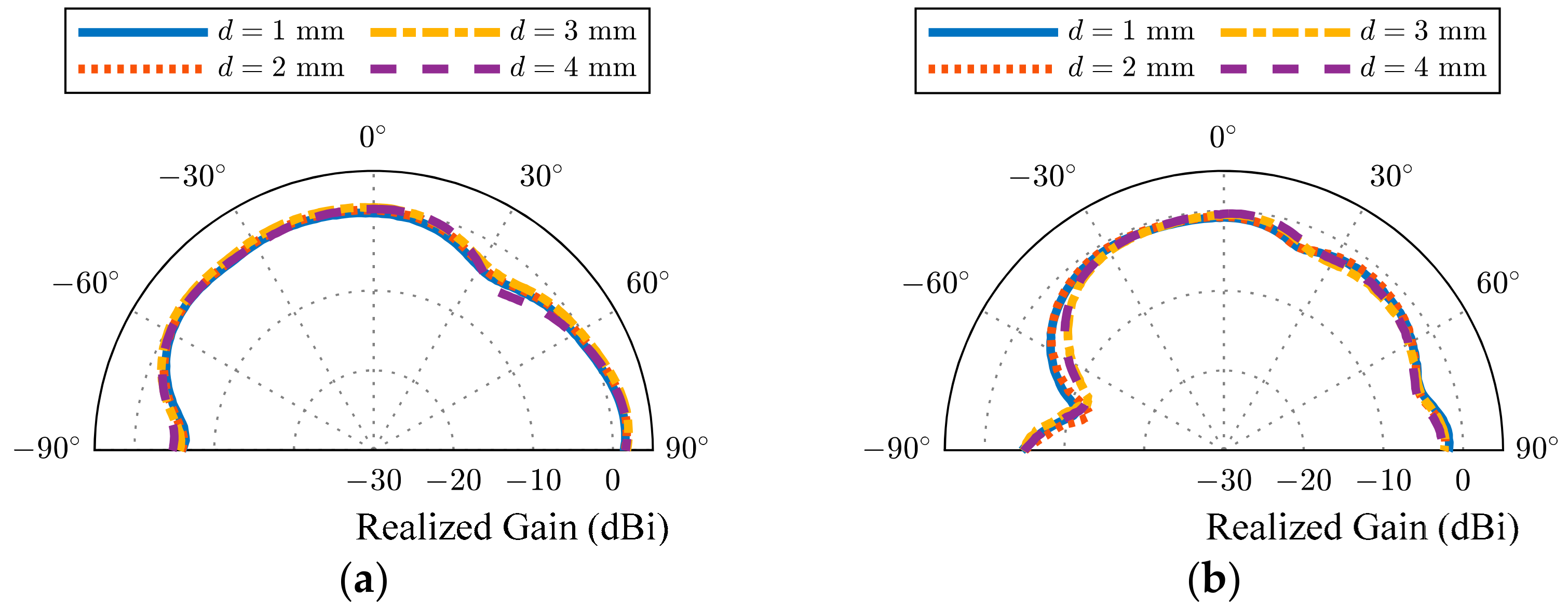
The presented ESA with a cylindrical cavity and a dielectric block length of 22 mm was also simulated for the insertion of different metallic rods. The results are presented in
Figure 4. According to the results, the operational frequency of the ESA is tunable and depends on the metallic rod height. Such functionality is possible because the dielectric block was not used as a resonator, but only as an element that allows the dimensions of the radiation line to be reduced.
The resonant frequency of the presented ESA can be changed either by modifying the dimensions of the dielectric block or by changing the permittivity. Another method, which is proposed in this communication, is based on changing the insertion of a metallic rod into the cylindrical cavity drilled inside the dielectric block. We need to note that the size of the dielectric block has an effect on the resonant frequency; however, block sizes are chosen so as not to excite the resonant modes. To prove this, let us consider the resonant frequency of a rectangular cavity resonator, which, in a general case, could be calculated as
where
n, m, and
l are any integers, and
b, c, and
d are the dimensions of the dielectric block in the
x,
y, and
z directions. For each value of
m,
n, and
l, we obtained a specific type of resonance with the only difference being that one of the three indices can be equal to zero in the case of the lowest modes of the H-type (
f011 =
f101 = 5 GHz), and none of them can equal zero for the lowest mode of the E-type (
f111 = 6.3 GHz). Assuming that the resonator is fully filled with a dielectric with a permittivity of 11.2, then the resonant frequency will be at a lower frequency. The lowest resonant frequency will be around 1.5 GHz. In our case, the dielectric block was not fully metallized, but, rather, was partially open. It should be assumed that the effective permittivity of the dielectric block will be less than the value of
, and that the resonant frequency will be higher. This can also be proven by simulating the near-field distribution inside the dielectric block. Therefore, herein, the dielectric block was used only for shortening the radiator length, and its resonances were not utilized.
The design of the presented ESA was initially analyzed without the cylindrical cavity. Electromagnetic software FEKO was used to conduct a series of simulations and to find optimal dimensions for the antenna elements. The optimization revealed that the antenna resonated at 1216 MHz; hence, the corresponding free-space wavelength (λ) and the wavenumber (
k) were 246.7 mm and 25.468 rad/m, respectively. These values determine the fundamental bandwidth limitation due to a reduction in the dimension. The approximate normalized bandwidth (
B) for a given maximum voltage standing wave ratio (VSWR) in terms of the limit on the quality factor (
QL) can be found by [
12]
where
and
a is the radius enclosing the antenna. Since the antenna is linearly polarized, the fundamental limit for the minimum quality factor is
A theoretical limit of the relative bandwidth for a VSWR of 2:1 can be estimated using Equation (2) as follows:
which corresponds to 28 MHz of the absolute bandwidth.
Additional simulations were performed to examine the relationship between the dielectric block length and the resonant frequency. The length of the dielectric block was changed from 21 to 22 mm, with the other dimensions remaining unchanged. In
Table 1, the influence of the dielectric block length on the resonant frequency is presented. One can observe that changing the length of the dielectric block allowed us to choose the desired frequency of operation, i.e., each 0.5 mm shifted the central frequency by 25 MHz. Eventually, it was possible to easily redesign the ESA for various GNSSs, such as GPS, GLONASS, or BeiDou, only by changing the length of the dielectric block.
Table 1 also shows the efficiency of radiation, which slightly decreased with the dielectric block length. The length of 22 mm was chosen for the final design.
Figure 5 provides the far-field, 2D radiation patterns simulated at 1232 MHz in three planes (XOY, XOZ, and YOZ), which reflect the space distribution of the two field components,
Eθ and
Eφ.
Figure 5a,b presents the radiation patterns of the ESA with and without the metallic rod. The similarity between the obtained results indicates that the influence of the metallic rod on the radiation pattern is negligible. From the presented figures, it is clear why, apart from the omnidirectional radiation in the XOY plane, some radiation can be observed in the plane in the transverse directions of the antenna (i.e., the XOZ plane). In the XOZ plane, the radiation in the perpendicular direction (
z-axis) to the antenna was dominant based on the
Eφ component, which is in line with the surface current direction of the designed ESA (
Figure 2d).
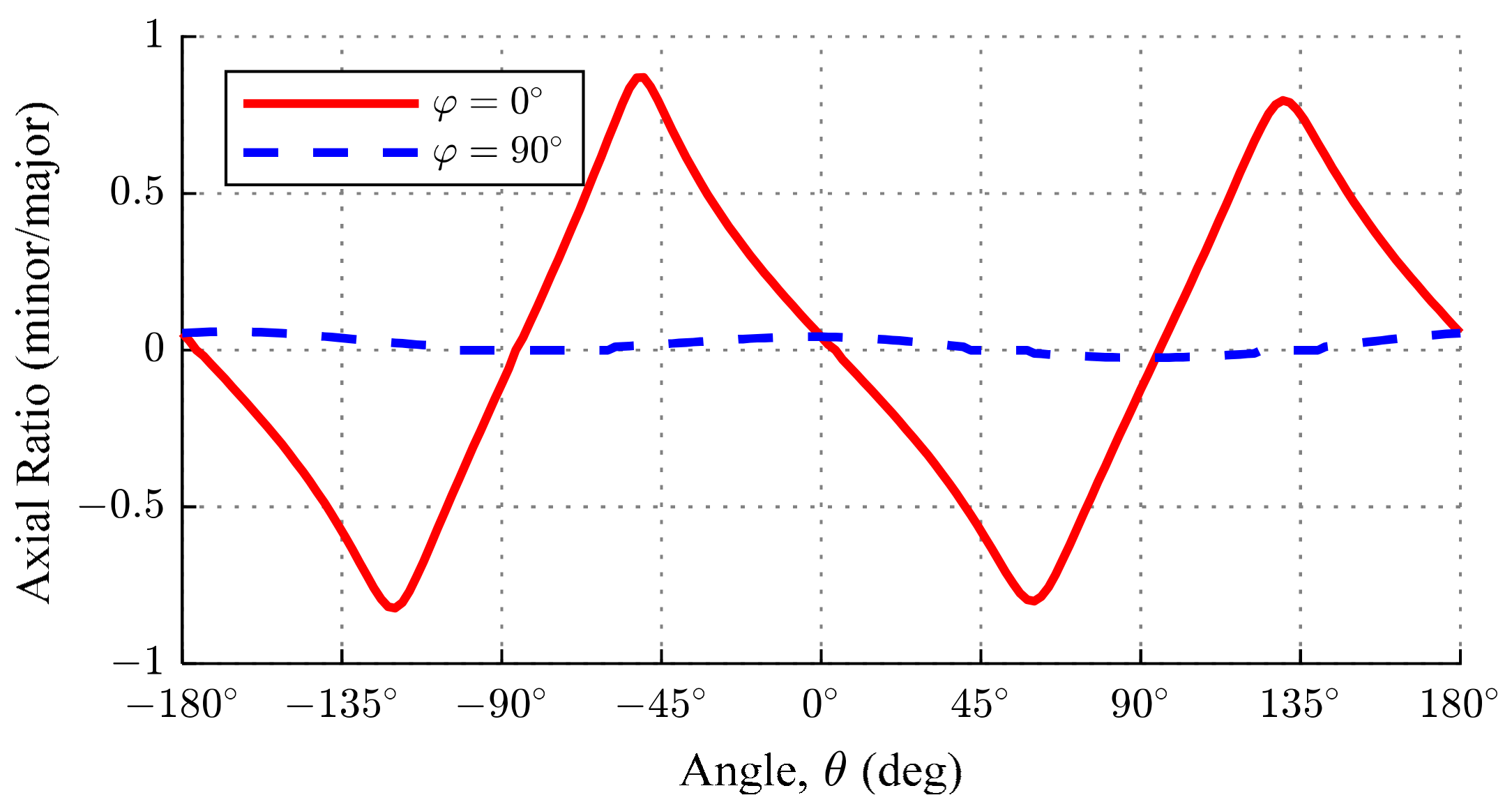
Figure 6 shows the axial ratio in two planes, namely, XOZ and YOZ, where it is very clear that the presence of
Eφ caused elliptical polarization in limited space. This functionality is very advantageous in navigation systems because the mutual positioning of the source and receiver is undefined and the polarization is not aligned.


 and
and 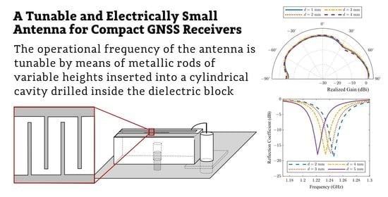


