1. Introduction
The Accademia Gallery in Florence is the fourth museum for numbers of visitors in Italy. This worldwide fame is due to its collection of Michelangelo’s sculptures, dominated by Michelangelo’s David. The Accademia Gallery was founded by Grand Duca Pietro Leopoldo in 1784 as an art museum for academics. In 1872 the architect E. De Fabris built the “Tribuna”, a space specifically designed for hosting Michelangelo’s David [
1]. After that, the structural configuration of the Gallery has not been changed but the building has undergone several maintenance and renovation works. In the 1980s a new ventilation system was installed under the floor of the “Tribuna” and the adjacent “Galleria dei Prigioni”.
The evaluation of the stability of Michelangelo’s David has enlivened the scientific discussion over time [
2,
3,
4,
5,
6]: the statue is affected by visible cracks on the legs, first observed between 1852 and 1872. In 2006 Borri and Grazini [
2,
3], on the basis of a historical analysis and a finite element model of the statue, identified the likely causes of the cracks: a slight forward inclination of the statue that ocurred after the Florence flood of 1844. The additional weight placed on the statue by Clemente Papi in 1847 to make a plaster cast contributed to the damage. Some scholars [
4] have suggested that the weakness of its legs could make the statue sensitive to the daily visitors walking by. Therefore, in 2017 Pieraccini et al. [
5] monitored the dynamic displacements of Michelangelo’s David by means of an interferometric radar. The measurement results did not show a significant increase of the vibration amplitude during the opening days of the Academia with respect to closing days.
In 2010 Borri et al. [
6] performed a GPR survey of the basement and of the pavement surrounding the David. The survey of the whole floor was prevented by the security shield around the basement. This survey was performed using 1600 MHz antennas on the basement and 600 MHz antennas on the floor. The results showed the presence of a metallic grid under the tiles (around the basement) and a metallic anchoring system inside the basement.
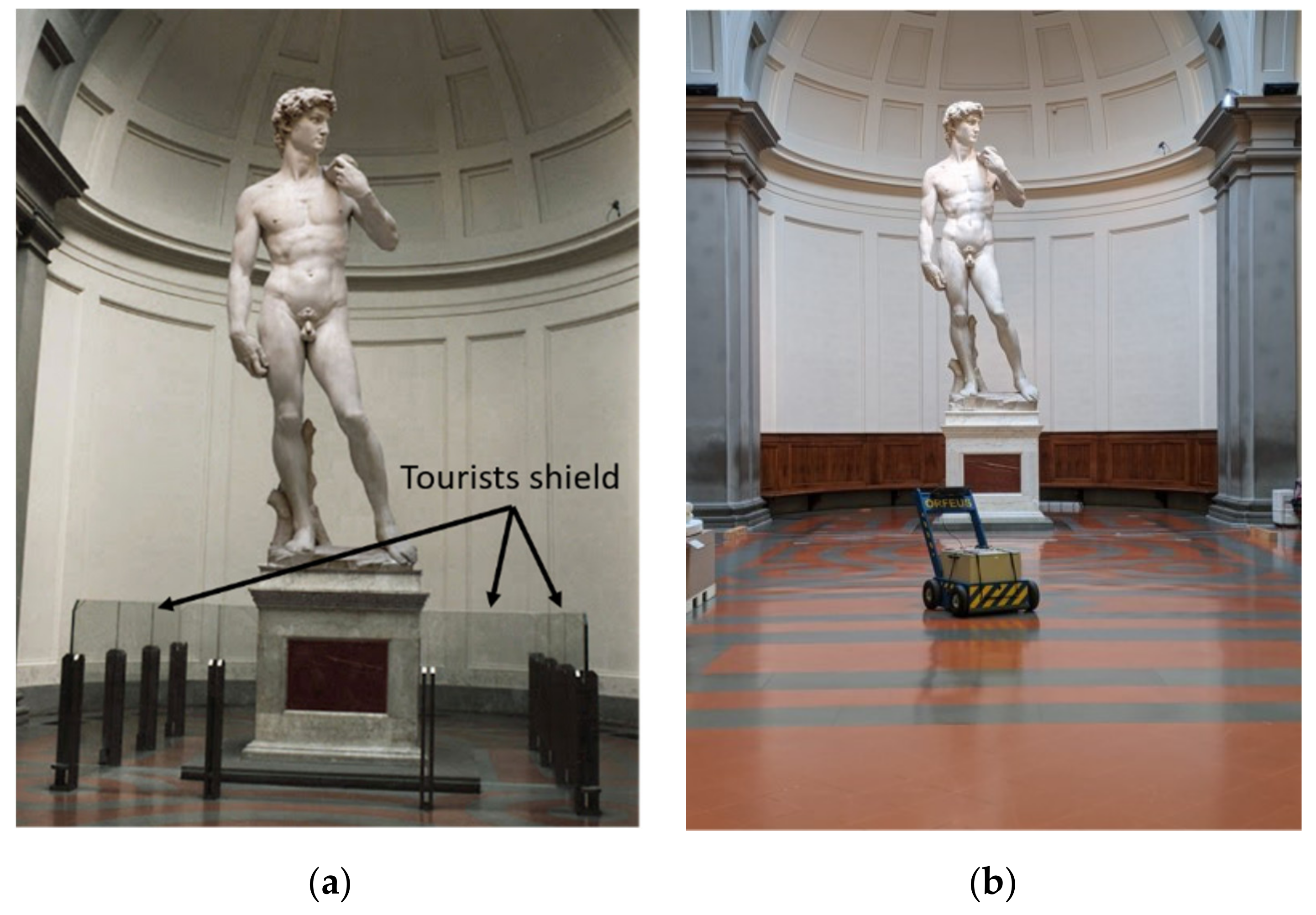
This paper reports the results of a new GPR survey performed from December 2020 to January 2021. Within this period the security glass shield around the Michelangelo’s David was removed (see
Figure 1), thus making it possible to investigate the whole area around the statue. This was a unique opportunity to carry out a full-floor orthogonal survey of the “Tribuna”.
2. Materials and Methods
2.1. The “Tribuna”
The “Tribuna” is located at the end of the “Galleria dei Prigioni”. It has a square plan with 8.70 m long sides, and it ends in an exedra. The central area, where the statue is located, is covered with a circular skylight which ensures natural lighting.
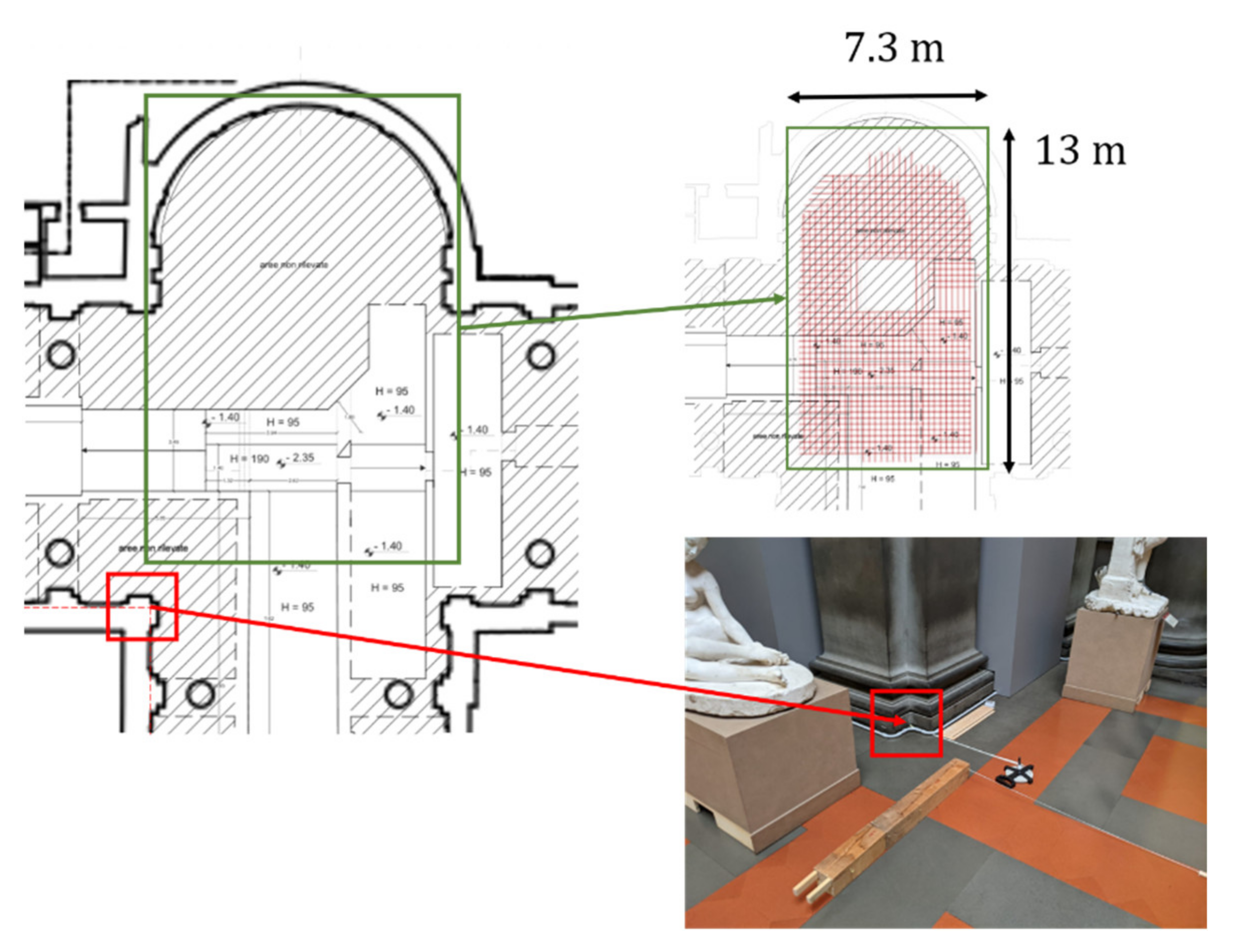
The underground level of the “Galleria dei Prigioni” and the “Tribuna” hosts technical spaces. The underground planimetry of this area is shown in
Figure 2 and
Figure 3.
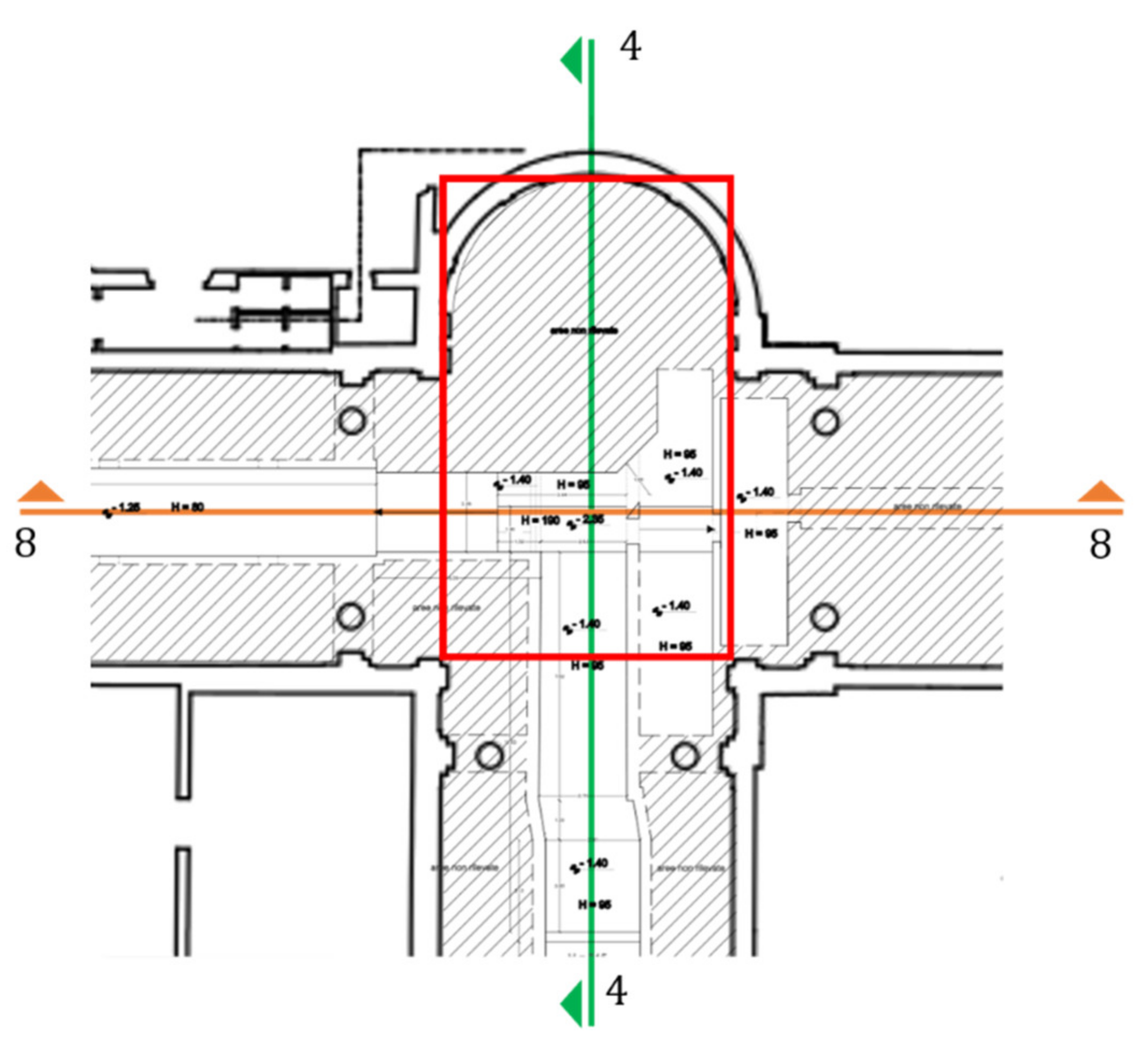
Figure 2 shows the plan of the “Tribuna” overlapped to the layout of the underground air-conditioning ducts. The corridor of the ducts is about
wide.
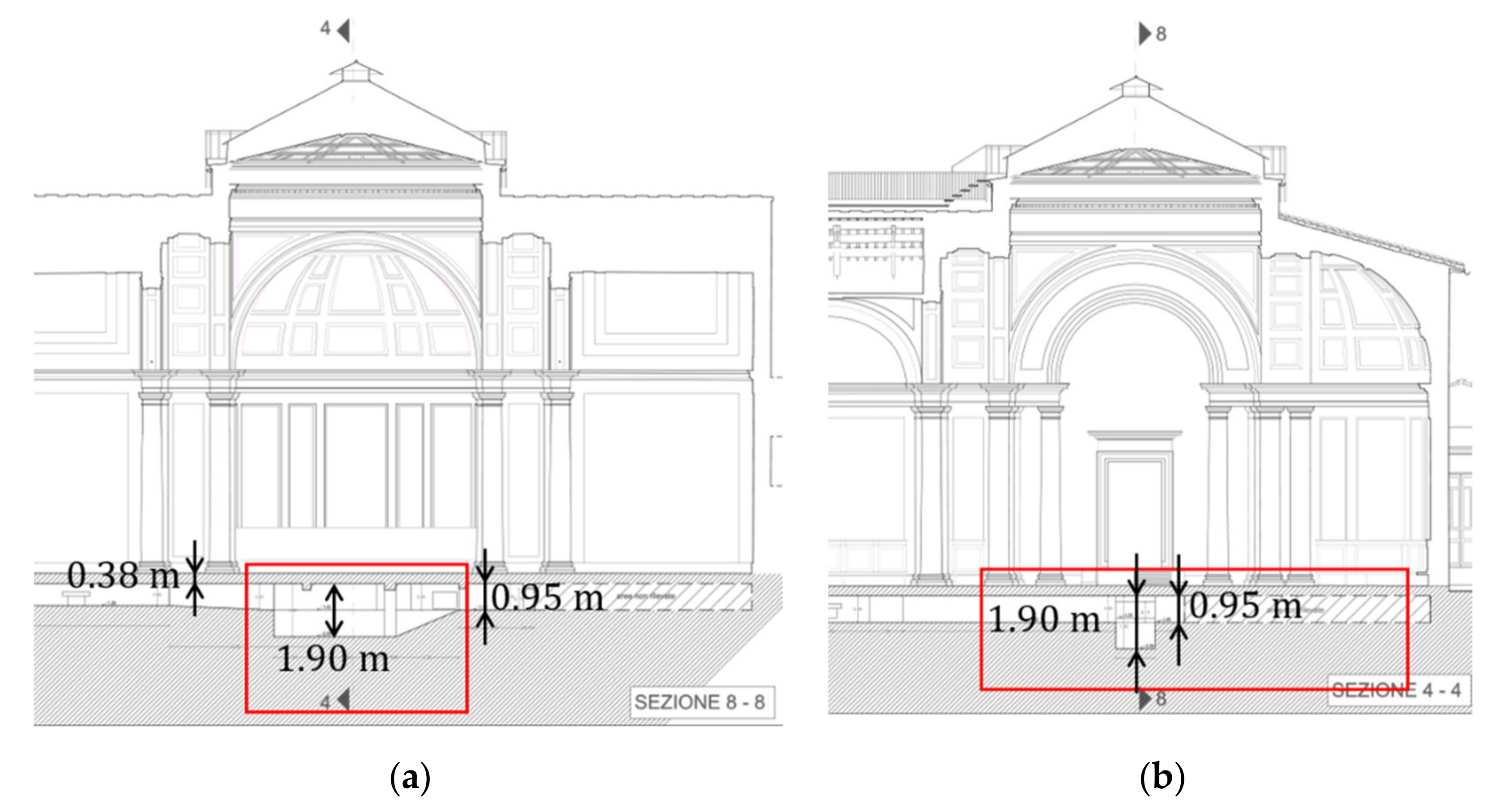
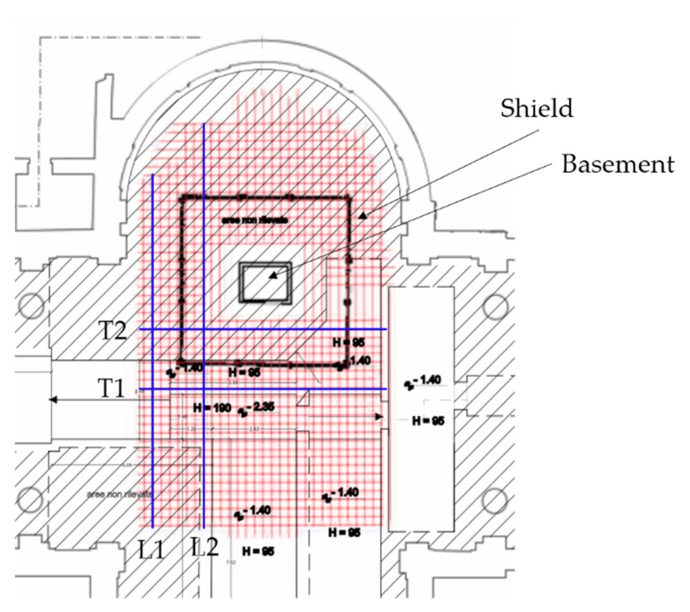
Figure 3 shows the vertical sections labeled with
and
in
Figure 2. They show that the corridor height varies from 0.95 m to 1.90 m. As reported below, the depth and the height of the corridor were used to calibrate the average speed of the electromagnetic wave inside the floor. The GPR survey was performed on the volume spotlighted by the red rectangle in
Figure 2 and
Figure 3.
2.2. Historical Documentation
The historical documentation of the Accademia Gallery [
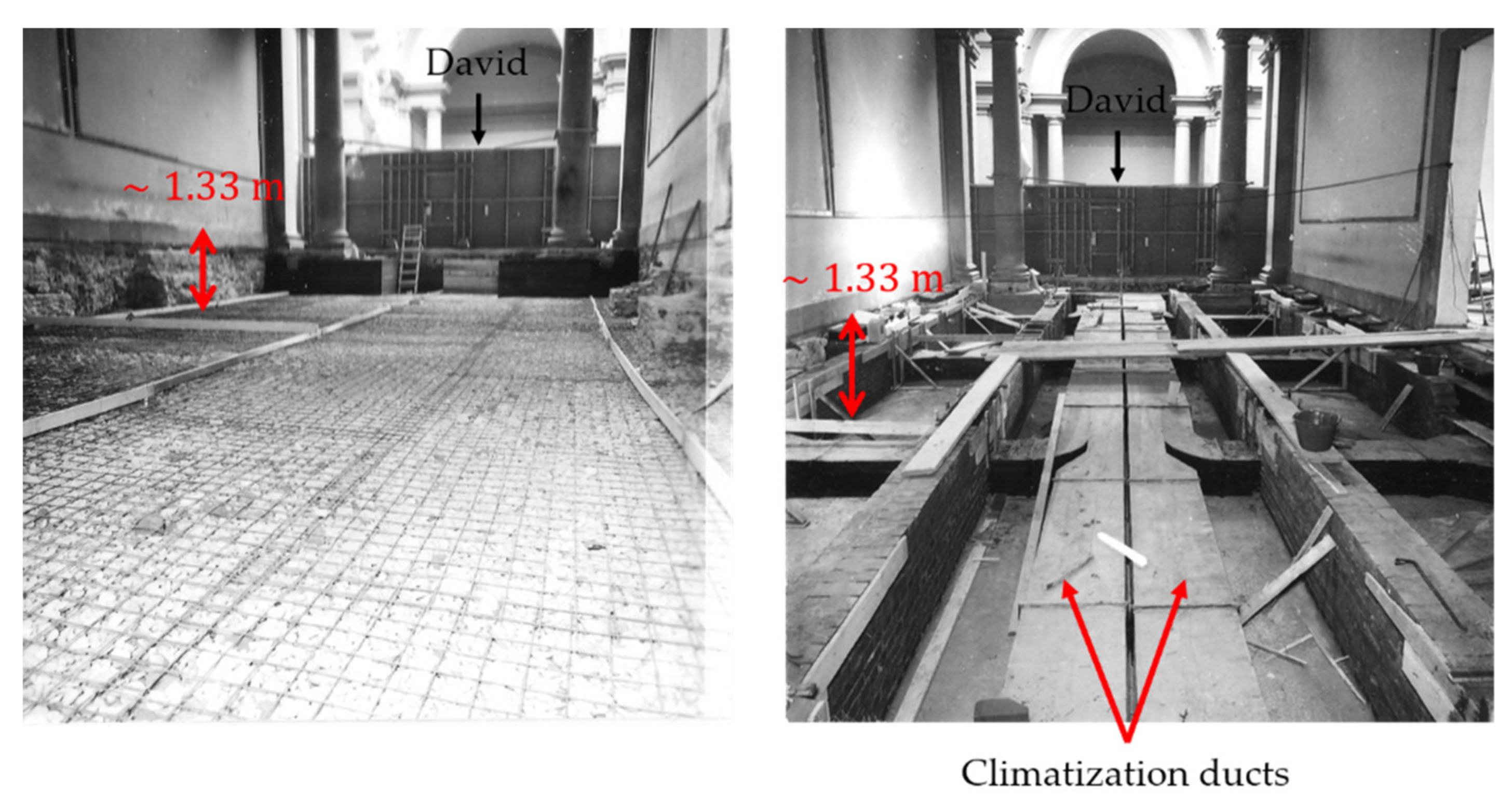
1] reports the renovation work done in the 1980s on the floor of the “Galleria dei Prigioni” and the “Tribuna” to host the air-conditioning ducts. During these works, several photos were taken. These photos are stored in the Photographic Archive of Superintendence BAPSAE of Florence, Pistoia, and Prato [
7].
Figure 4 shows two of these pictures (the David is in the background behind the scaffold). The ducts in the “Galleria dei Prigioni” are laid at about 1.33 m depth. The laying plan of the ducts is made by welded mesh.
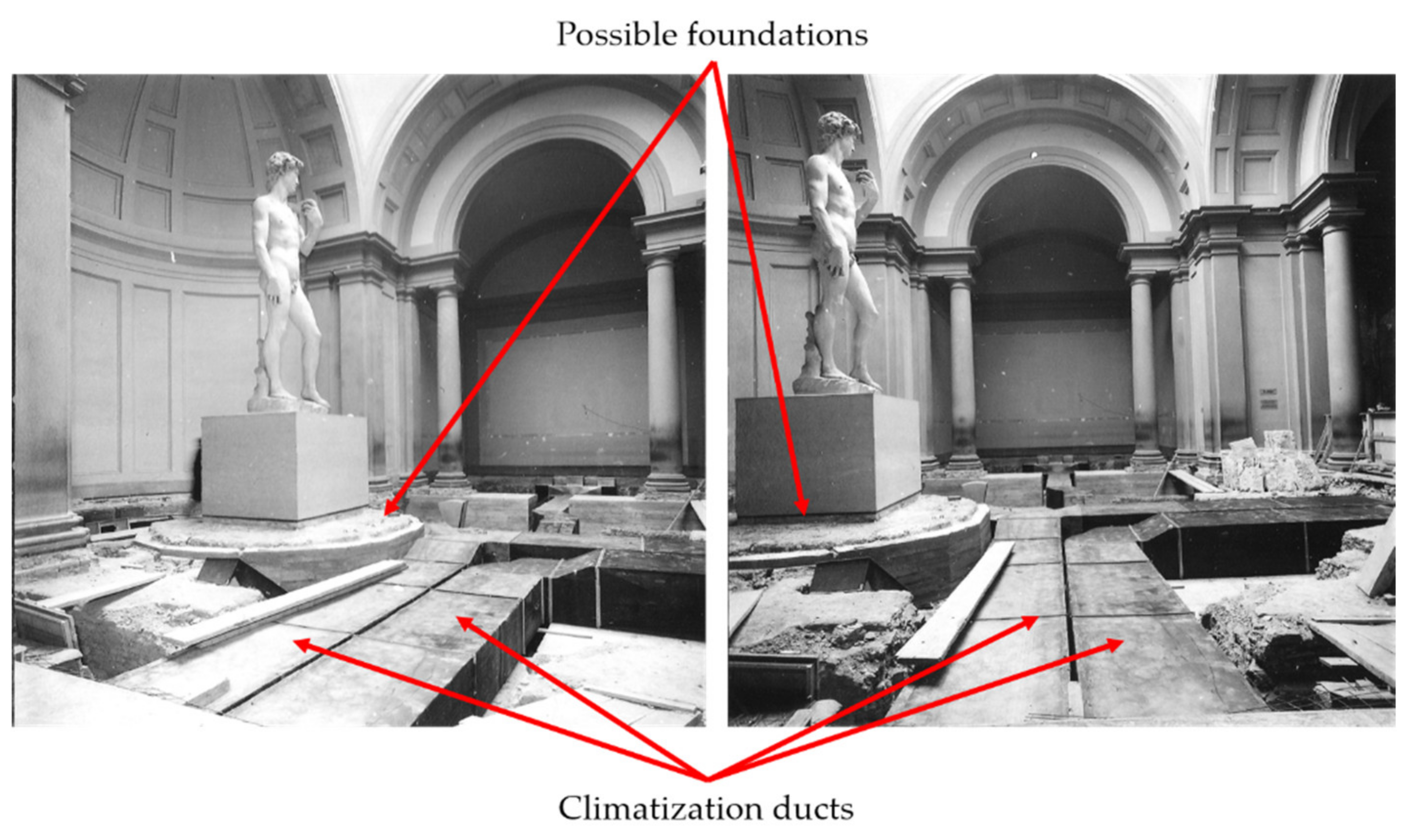
Figure 5 reports two pictures showing the works around the Michelangelo’s David. The basement of the statue appears covered with a wood structure (probably a protection during the works). Under the basement of the sculpture, a cylindrical structure can be noted which probably represents the foundation. To the authors’ knowledge, except for these pictures, there is no further historical documentation about this foundation.
2.3. The GPR Survey
GPRs have been used for civil engineering purposes for decades [
8]. GPR is a technique that makes use of electromagnetic waves to map shallow discontinuities of the electrical proprieties of a propagation medium. These discontinuities can be associated to air-voids, metallic objects, and interfaces between different media. Illustrative applications of GRP survey on historical structures that can be mentioned are: an ancient building in Roccaspinalveti (Chieti, Italy) [
9], an Ottoman building in Urla (Izmir, Turkey) [
10], the Valencian Cathedral (Spain) [
11], and the “Santa Maria del Mar” Chatedral in Barcelona (Spain) [
12]. Recently, Pieraccini et al. [
13] by using GPR discovered the remains of the foundation of the Italian Parliament of 1864 below the floor of “Salone dei Cinquecento” in “Palazzo Vecchio” in Florence (Italy).
From a technical point of view, the GPR can provide pulse or continuous wave (CW) signals. Pulse GPRs are more popular as their hardware is simpler and cheaper, but the performances of a CW radar can be significantly better in terms of resolution and penetrating depth [
14,
15]. The survey of the “Tribuna” was performed using ORFEUS GPR [
16,
17,
18]. ORFEUS provides a Continuous Wave Step Frequency (CWSF) signal sweeping from
to
in 201 steps. The dynamic range is 100 dB with repetition rate
. The unambiguous range is about
in air (at least 10 m in ground). ORFEUS is equipped with a couple of co-polarized antennas with a central frequency of 200 MHz and bandwidth of about 200 MHz. The GPR is equipped with a digital odometer.
The GPR measurements were co-registered in a grid with a pitch of 0.20 m. The survey covered an area of
, as shown in
Figure 6. The scans were performed along two orthogonal directions. Acquisitions in the same direction were separated by 0.25 m from each other. A column (
Figure 6) was used as origin of the reference system.
Figure 7 shows the grid of the survey. The survey was composed by 39 longitudinal scans and 53 transversal scans.
Radar data were analyzed using GRED 3D by IDS georadar, Pisa, Italy. Each scan was processed with a background removal procedure and with a gain compensation of the exponential loss. The B-Scans were interpolated for retrieving the C-scan. The speed of the electromagnetic waves was estimated by comparing the depths of the vertical sections (
Figure 3 and
Figure 4) with the B-scan images. The estimated value was
.
3. Results
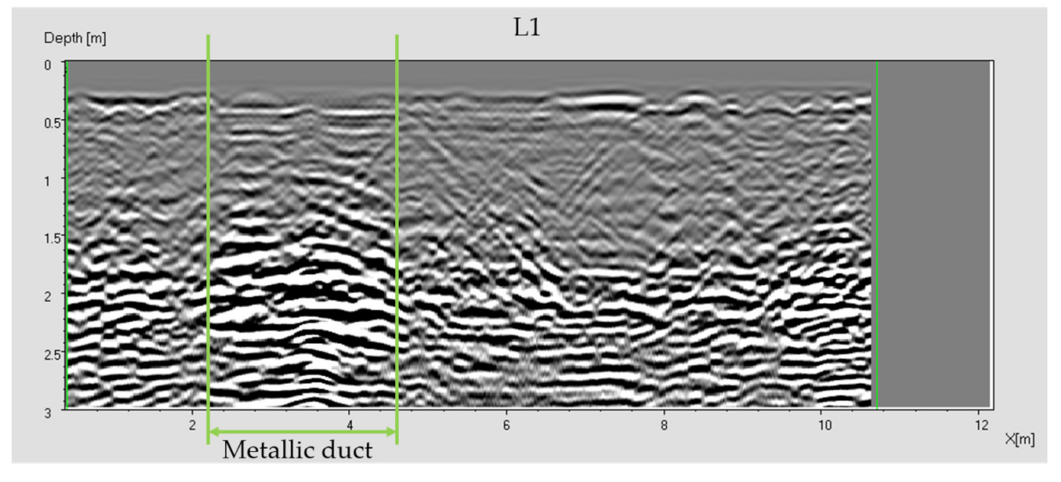
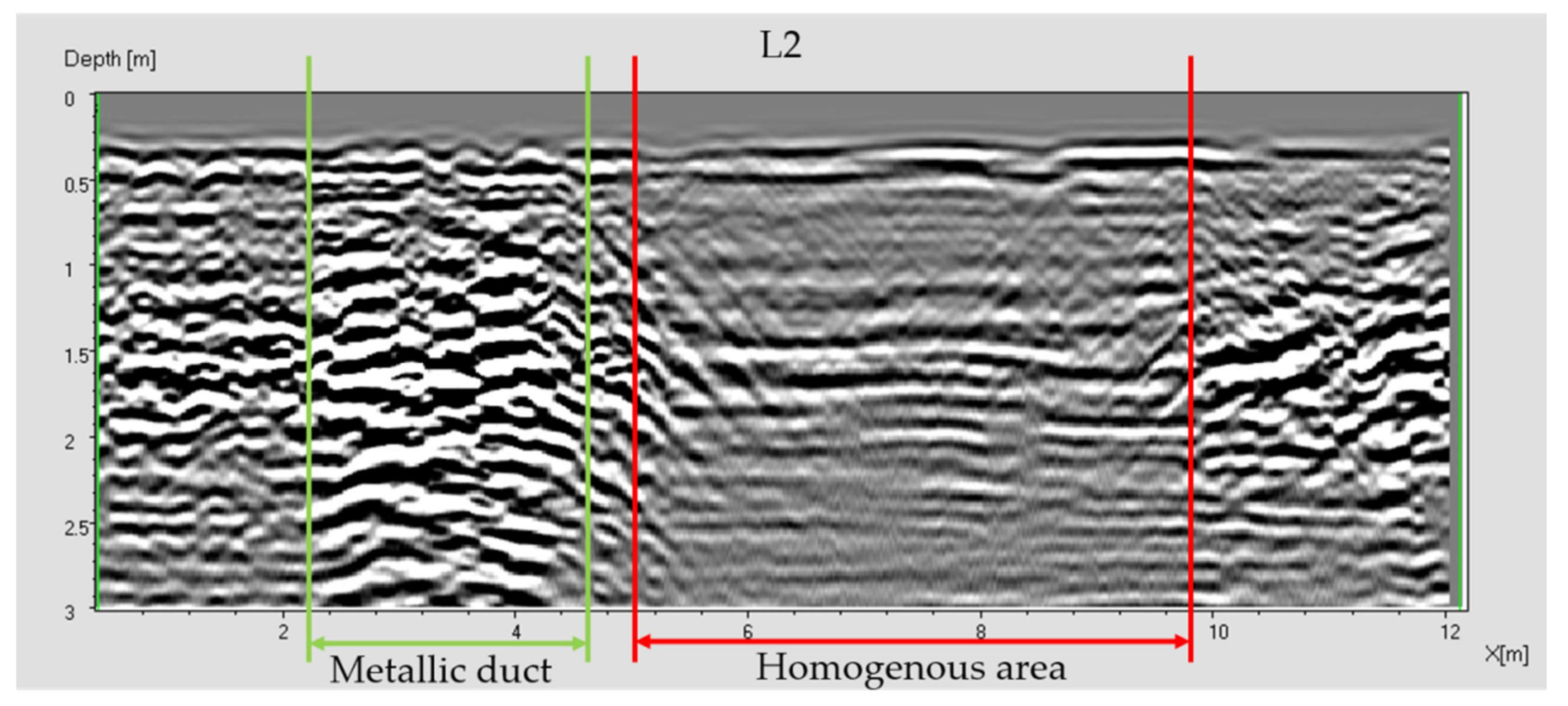
Figure 8 and
Figure 9 show the B-scans L1 and L2 (with reference to
Figure 7). The area on the left (marked with two vertical green lines) is related to the air-conditioning ducts. The metallic ducts give a strong reflection that shields the targets below them. The ducts area is characterized by a typical ringing effect. The signals due to the same metallic ducts in L1 and L2 could appear a bit different. But this is probably due to the background removal procedure, that operates differently in scans with different features. Furthermore, ringing is strongly depending on small geometrical features of the target. So, the same metallic duct may or may not give ringing at different sections.
The area on the right (marked with two red lines in
Figure 9) reveals the presence of a homogeneous and highly attenuating medium. The thickness of this medium is about
. Sharp vertical interfaces between the homogeneous medium and the surrounding masonry at
and
are observed. It is supposed that this homogeneous medium corresponds to a pouring of concrete, as also confirmed by the photographic documentation (see
Figure 5).
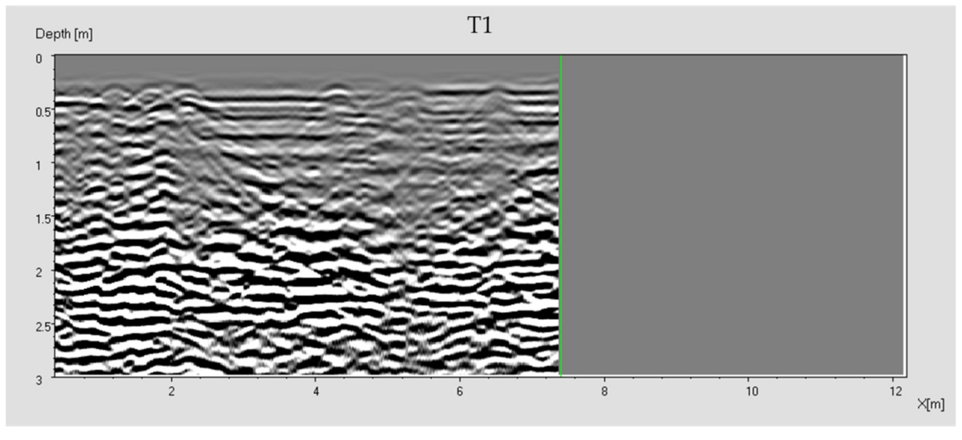
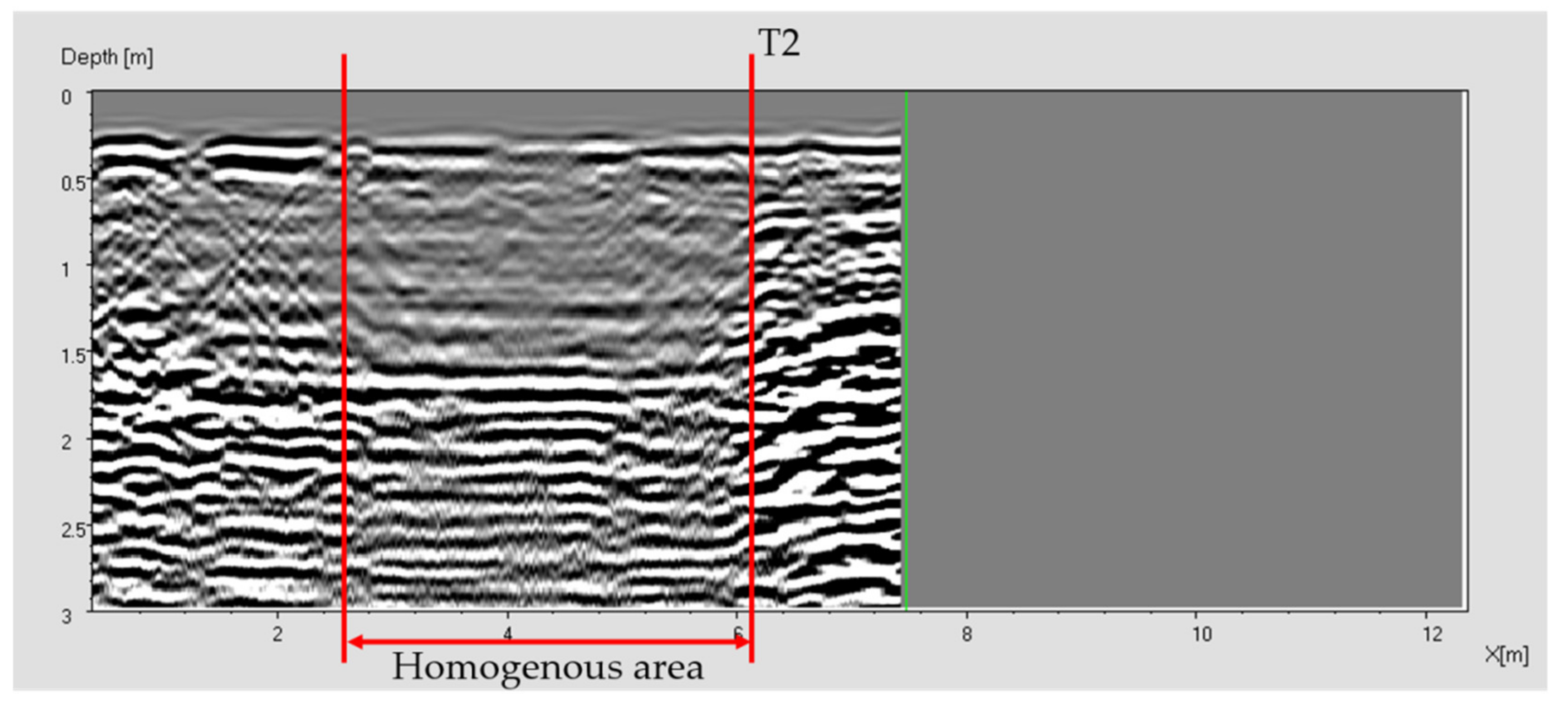
Figure 10 and
Figure 11 show the B-scans T1 and T2 (with reference to
Figure 7). The T1 scan corresponds to the area above the ducts. In T2 scan (
Figure 11) the homogeneous area is clearly visible from
to
. The depth of this area is about
.
The C-scans (i.e., radar image in the horizontal plane) were obtained by interpolating the B-scans.
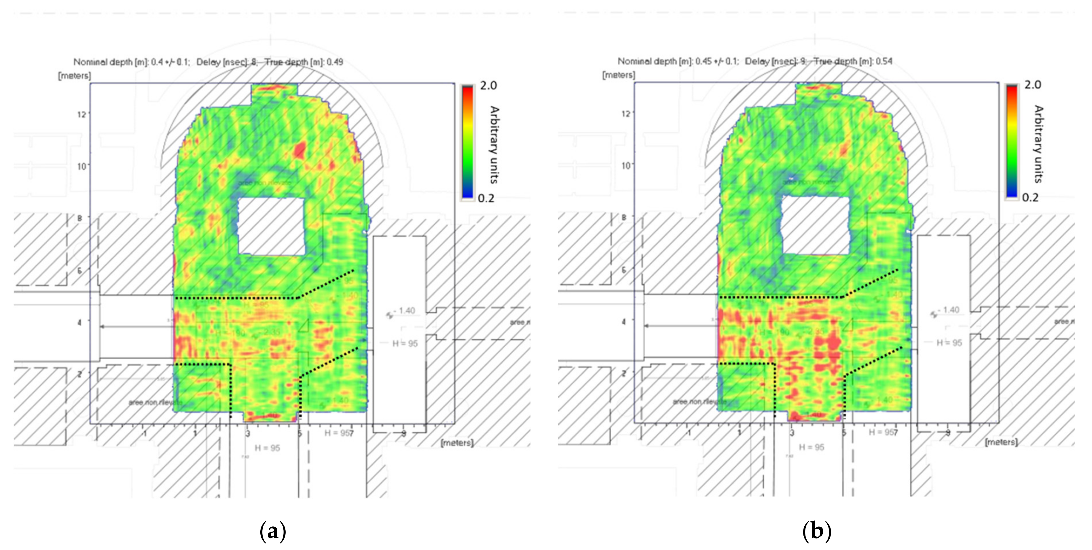
Figure 12 shows the C-scan at
depth (
Figure 12a) and at
depth (
Figure 12b). The air-conditioning ducts are clearly recognizable, and they are spotlighted by a dotted line. Around the basement a homogeneous zone can be detected (especially at higher depths). It can be interpreted as the David foundation.
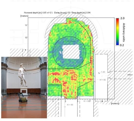
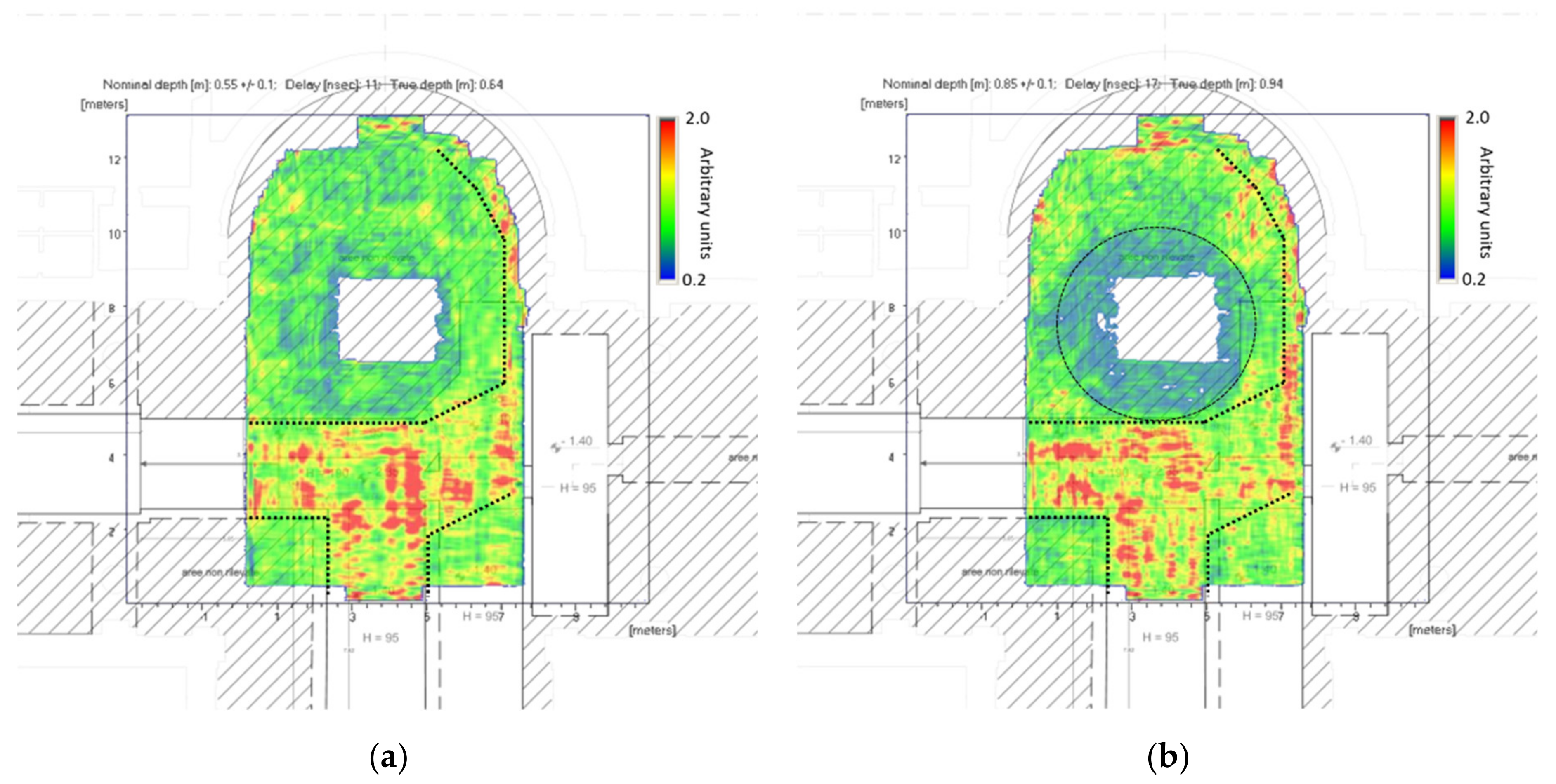
Figure 13a shows the C-scan at
depth. In this image the shape of the foundation is just detectable. In this C-scan it is also possible to observe the duct that feeds the air vents in the hemicycle. This duct is not reported in the planimetry.
Finally, in
Figure 13b the circular David foundation is clearly visible. This C-scan corresponds to a depth of
. This area appears homogeneous and highly attenuating.
4. Discussion
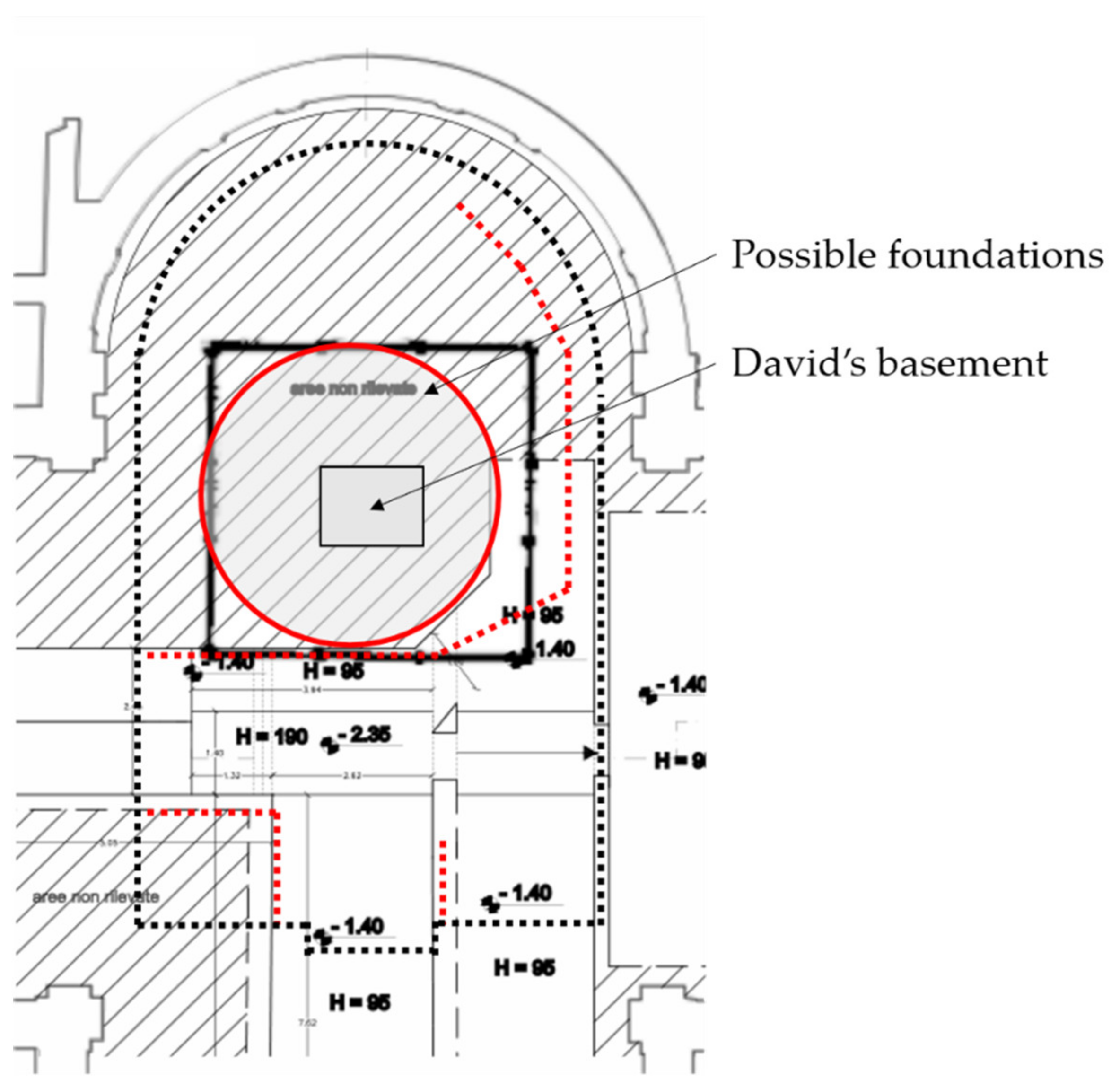
Figure 14 schematically shows the results of the GPR survey. The black dotted line shows the area of the survey. The red dotted lines are related to the radar signals given by the air-conditioning ducts. Their positions are in agreement with the available planimetry and the photographic documentation. An additional duct was detected in the right part of hemicycle. This duct feeds the air vents in the hemicycle of Tribuna.
The red circle corresponds to the foundation below the basement. This structure is about in size. It is electromagnetically homogeneous and strongly attenuating (at the frequency of ). It is worth noting that the detected foundation is not exactly centered with the basement of the statue.
5. Conclusions
A GPR survey was performed on the floor of “Tribuna” of Accademia Gallery (Florence, Italy) around the basement of Michelangelo’s David.
The survey results have been compared with planimetry and historical photographic documentation. The survey confirmed the layout of the air-conditioning ducts dated 1980. A feed duct for the air vents (not reported in the planimetry) was found on the right of the hemicycle of the “Tribuna”.
The position of the David foundation corresponds to what can be retrieved from the historical photos. Anyway, the foundation does not appear centered with the basement of the statue. The medium of this foundation is very homogeneous and strongly attenuating at . It is supposed that it consists of concrete as suggested by the historical photographic documentation.
Author Contributions
Methodology, L.M.; validation, L.M., M.P. and S.M.; formal analysis, A.B.; investigation, S.M.; resources, M.B. and C.B.; data curation, L.M.; writing—original draft preparation, L.M.; writing—review and editing, L.M. and S.M.; visualization, L.M.; supervision, M.P. and M.B.; project administration, M.B. and C.B.; funding acquisition, M.B. and C.B. All authors have read and agreed to the published version of the manuscript.
Funding
The postdoctoral research fellowship of one of the authors (S.M.) was founded by the Tuscany Region and the Accademia Gallery of Florence.
Institutional Review Board Statement
Not applicable.
Informed Consent Statement
Not applicable.
Data Availability Statement
Data available on request.
Conflicts of Interest
The authors declare no conflict of interest. The funders had no role in the design of the study; in the collection, analyses, or interpretation of data; in the writing of the manuscript, or in the decision to publish the results.
References
- Giorgianni, G. (Ed.) La Valutazione del Rischio Sismico nel Complesso della GALLERIA dell’Accademia di Firenze: Un’Applicazione Sperimentale delle “Linee Guida MiBACT per la Valutazione e Riduzione del Rischio Sismico del Patrimonio Culturale (2009–2013); Altralinea Edizioni: Firenze, Italy, 2018. (In Italian) [Google Scholar]
- Borri, A. La Stabilità delle Grandi Statue: Il David di Michelangelo; DEI: Rome, Italy, 2005. (In Italian) [Google Scholar]
- Borri, A.; Grazini, A. Diagnostic analysis of the lesions and stability of Michelangelo’s David. J. Cult. Herit. 2006, 7, 273–285. [Google Scholar] [CrossRef]
- Corti, G.; Costagliola, P.; Bonini, M.; Benvenuti, M.; Pecchioni, E.; Vaiani, A.; Landucci, F. Modelling the failure mechanisms of Michelangelo’s David through small-scale centrifuge experiments. J. Cult. Herit. 2015, 16, 26–31. [Google Scholar] [CrossRef]
- Pieraccini, M.; Betti, M.; Forcellini, D.; Dei, D.; Papi, F.; Bartoli, G.; Facchini, L.; Corazzi, R.; Kovacevic, V.C. Radar detection of pedestrian-induced vibrations on Michelangelo’s David. PLoS ONE 2017, 12, e0174480. [Google Scholar] [CrossRef] [PubMed] [Green Version]
- Borri, A.; Faella, G.; Ferri, L.; Guadagnuolo, M. Indagini Georadar sul Basamento del David di Michelangelo; La scuola di Pitagora: Napoli, Italy, 2010. (In Italian) [Google Scholar]
- «Home—Firenze BAP». Available online: http://www.sbap-fi.beniculturali.it/ (accessed on 3 February 2021).
- Grandjean, G.; Gourry, J.C.; Bitri, A. Evaluation of GPR techniques for civil-engineering applications: Study on a test site. J. Appl. Geophys. 2000, 45, 141–156. [Google Scholar] [CrossRef]
- Orlando, L.; Slob, E. Using multicomponent GPR to monitor cracks in a historical building. J. Appl. Geophys. 2009, 67, 327–334. [Google Scholar] [CrossRef]
- Kilic, G. Using advanced NDT for historic buildings: Towards an integrated multidisciplinary health assessment strategy. J. Cult. Herit. 2015, 16, 526–535. [Google Scholar] [CrossRef]
- Perez-Gracia, V.; Canas, J.A.; Pujades, L.G.; Clapés, J.; Caselles, O.; Garcıa, F.; Osorio, R. GPR survey to confirm the location of ancient structures under the Valencian Cathedral (Spain). J. Appl. Geophys. 2000, 43, 167–174. [Google Scholar] [CrossRef]
- Perez-Gracia, V.; Caselles, O.; Clapes, J. Ground penetrating radar assessment of historical buildings: The study of the roofs, columns and ground of Santa Maria del Mar, in Barcelona. In Proceedings of the IEEE 15th Mediterranean Microwave Symposium (MMS), Lecce, Italy, 30 November–2 December 2015. [Google Scholar]
- Pieraccini, M.; Miccinesi, L.; Conti, A.; Fiorini, L.; Tucci, G.; Pieri, I.; Corazzini, S. Integration of GPR and TLS for investigating the floor of the “Salone dei Cinquecento” in Palazzo Vecchio, Florence, Italy. Archaeol. Prospect. 2020, 1–6. [Google Scholar] [CrossRef]
- Pieraccini, M. Noise performance comparison between continuous wave and stroboscopic pulse ground penetrating radar. IEEE Geosci. Remote Sens. Lett. 2018, 15, 222–226. [Google Scholar] [CrossRef]
- Hamran, S.E.; Gjessing, D.T.; Hjelmstad, J.; Aarholt, E. Ground penetrating synthetic pulse radar: Dynamic range and modes of operation. J. Appl. Geophys. 1995, 33, 7–14. [Google Scholar] [CrossRef]
- Parrini, F.; Pieraccini, M.; Grazzini, G.; Spinetti, A.; Macaluso, G.; De Pasquale, G.; Testa, C. ORFEUS GPR: A very large bandwidth and high dynamic range CWSF radar. In Proceedings of the XIII International Conference on Ground Penetrating Radar, Lecce, Italy, 21–25 June 2010. [Google Scholar]
- Pieraccini, M.; Capineri, L.; Falorni, P.; Devis, D. GPR investigation of “Fortezza da Basso” (Lower Fortress) in Florence, Italy. In Proceedings of the 16th International Conference on Ground Penetrating Radar (GPR), Hong Kong, China, 13–16 June 2016. [Google Scholar]
- Pieraccini, M.; Miccinesi, L.; Canizares, H.G. Critical verification of the underground cartography of the municipality using a high performance Ground Penetrating Radar. In Proceedings of the 10th International Workshop on Advanced Ground Penetrating Radar, The Hague, The Netherlands, 8–12 September 2019. [Google Scholar]
| Publisher’s Note: MDPI stays neutral with regard to jurisdictional claims in published maps and institutional affiliations. |
© 2021 by the authors. Licensee MDPI, Basel, Switzerland. This article is an open access article distributed under the terms and conditions of the Creative Commons Attribution (CC BY) license (http://creativecommons.org/licenses/by/4.0/).


 ,
, 


