1. Introduction
As a highly controllable lightning measurement method, rocket-triggered lightning has been used to study the physical processes and discharging mechanism of natural lightning flashes [
1,
2,
3,
4]. Due to the relatively long duration, the initial stage is the main phase of cloud-to-ground charge transfer in triggered lightning [
5,
6], and the current change of the initial stage is related to the complex discharging processes in thunderclouds [
7,
8]. Therefore, the research on the electromagnetic radiation during the initial stage of triggered lightning provides valuable technical means for revealing the physical mechanism of the lightning discharging process.
The initial stage of triggered lightning usually refers to the process from the inception of the upward leader to the initial continuous current (ICC) [
7,
9]. Before the inception of the upward leader, the breakdown would occur at the tip of steel wire, which produces intermittent current pulses with strength of tens to hundreds of amperes [
10,
11]. This breakdown attempting to form an upward leader is referred to as a ‘precursor’ [
12], which is closely related to the initial stage [
13]. However, there are limited studies on the whole development of the initial stage including the precursor, and the relevant studies would shed light on the physical mechanism of leader inception and propagation.
The research on the initial stage of triggered lightning was mainly based on the measurement of channel-base current and fast/slow electric field (E-field) [
12,
14]. However, the magnetic field (B-field) measurement is also an important tool to study the physical process of lightning discharge. Different from the E-field measurement, the B-field is not easily distorted by the ambient surface obstacles. Rakov [
14,
15] observed the ICC in triggered lightning using magnetic loop antennae. Due to the limitation on the resolution and sensitivity of magnetic loop antennae, it is difficult to acquire the electromagnetic signals associated with relatively weak discharging processes. Lu [
16] observed the B-field signals during the very initial stage of triggered lightning by using a sensitive magnetic sensor with two orthogonal induction coils in the SHandong Triggering Lightning Experiment (SHATLE) campaign of 2014. Some measurements indicate that the rising time of pulses at the very initial stage could be as narrow as 2 μs [
9,
17,
18], and therefore the radiation of the upward leader in the medium frequency band cannot be ignored [
19]. As the 3-dB bandwidth of the magnetic sensor mentioned above ranged from 6 to 340 kHz (low frequency) [
16], the bandwidth is insufficient to examine the radiation characteristics of B-field at the initial stage in triggered lightning [
16,
20,
21,
22]. Therefore, it is necessary to expand the bandwidth of existing magnetic sensors to characterize the medium-frequency B-field during the initial stage development.
The magnetic sensor installed in the triggered lightning experiment of Field Experiment Base on Lightning Sciences, China Meteorological Administration (CMA-FEBLS) was improved in the summer campaign of 2019. The 3-dB bandwidth of the sensor was extended to 20 kHz–1.2 MHz. In this paper, the characteristics of B-field radiation during the initial stage of a triggered lightning flash were analyzed by using the new low-frequency and medium-frequency (LF-MF) magnetic sensor, as well as the channel-base current and fast E-fields concurrently observed in the experiment.
2. Measurements and Data
The triggered lightning experiment of CMA-FEBLS (see Abbreviations) is located in the Conghua District of Guangzhou City, Guangdong Province. It is previously known as the Guangdong Comprehensive Observation Experiment on Lightning Discharge (GCOELD) that continuously conducted the triggered lightning experiment since 2006 [
4,
23].
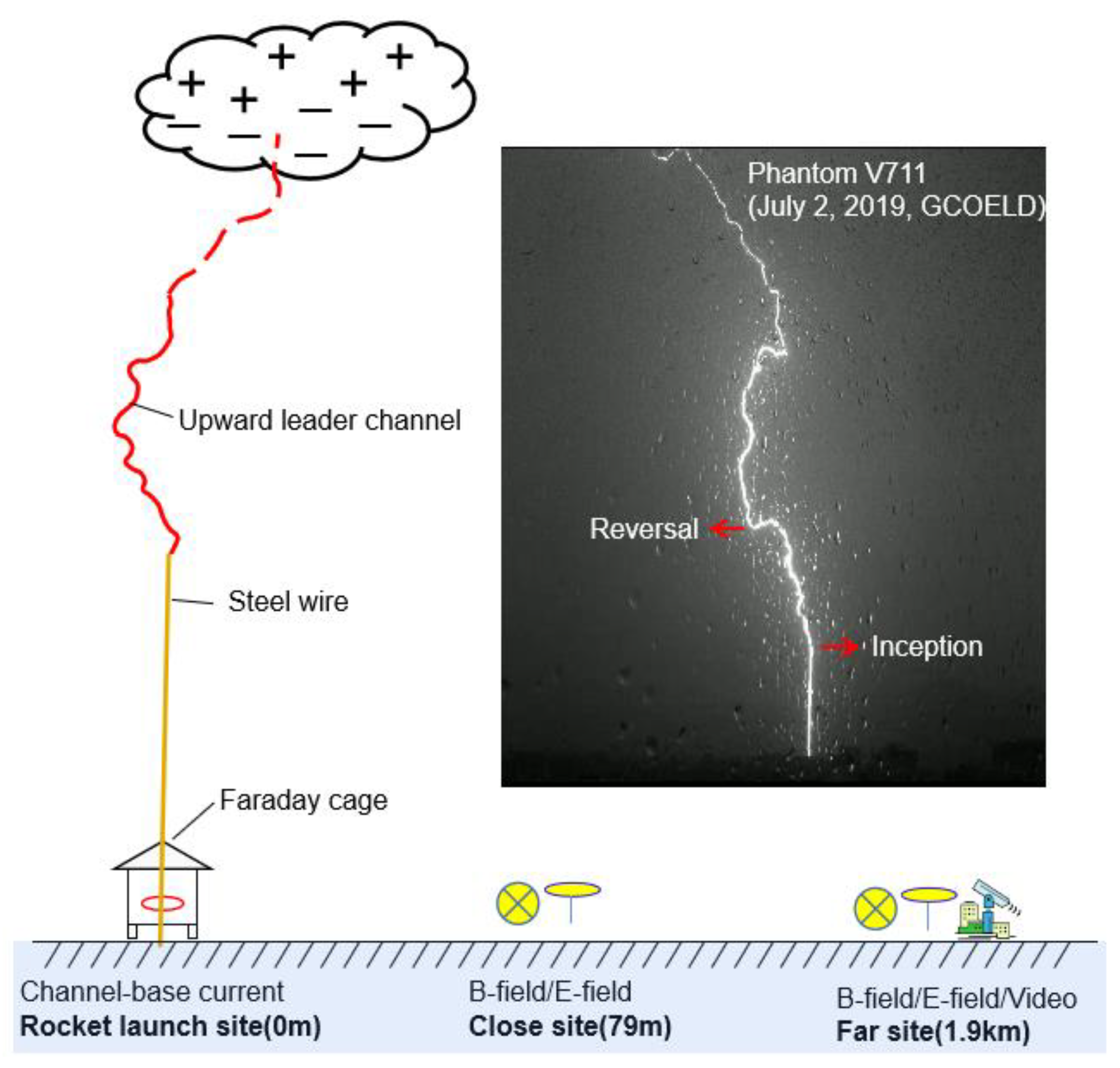
Figure 1 gives the sketch of the experiment setup for the CMA-FEBLS (23.64°N, 113.60°E) in the summer of 2019. The whole experimental field consisted of a rocket launching point, control room, close observation site and far observation site. The distance from the close site and far site to the rocket launching site was 79 m and 1.9 km, respectively.
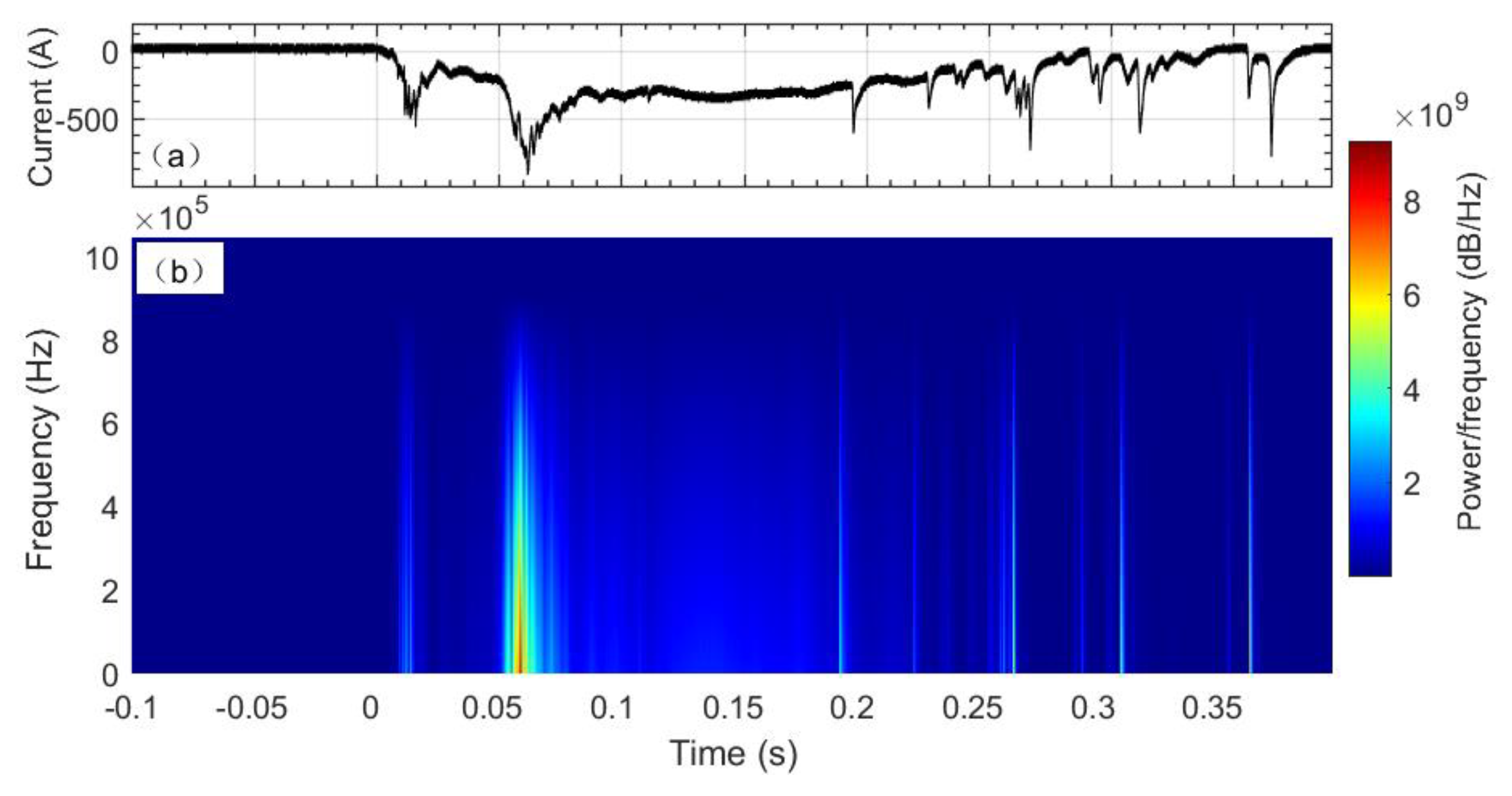
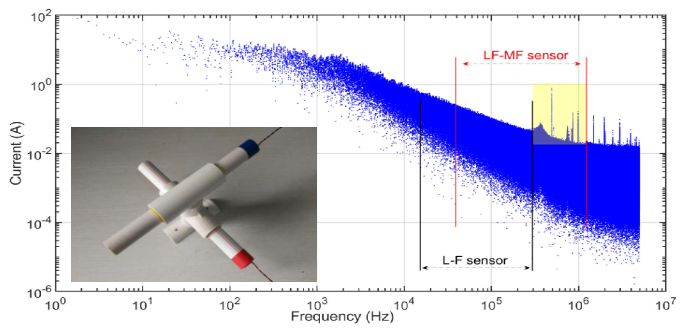
The lightning current was measured with a 1-mΩ coaxial shunt at the bottom of a lightning rod. The power spectrum of the channel-base current is shown in
Figure 2. The power spectrum peak of the current waveform approximately reached 9.0 × 10
9 dB/Hz, and the spectral region is in the range below 300 kHz. It is important to note that the power of the spectral region ranging from 300 kHz to 1 MHz is about 4.0 × 10
9 dB/Hz, so it shows the medium-frequency radiation of lightning current during the initial stage cannot be ignored [
19].
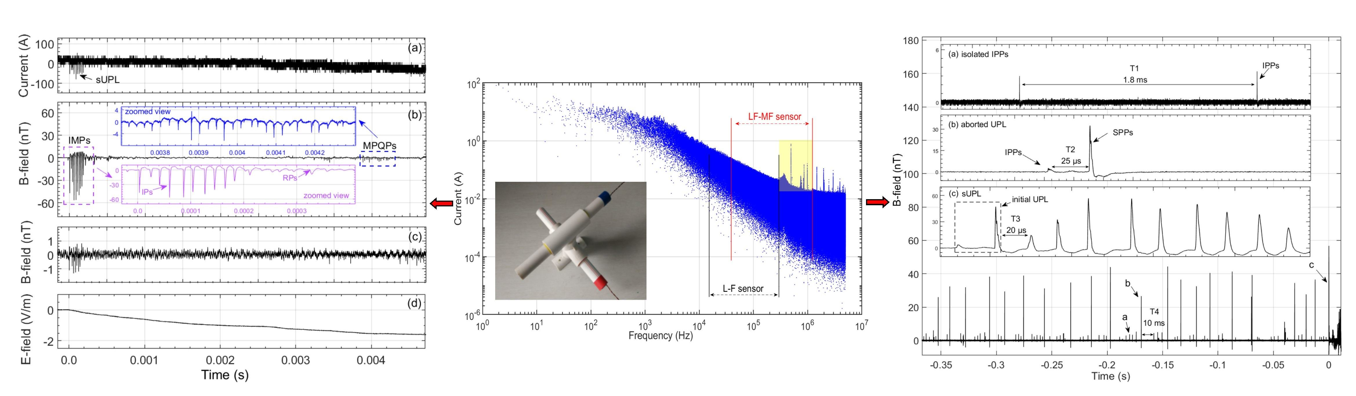
The Fourier transform of the current waveform is shown in
Figure 3; the frequency distribution between the two black lines represents the measurement range of the low-frequency sensor, while the red line represents the improved sensor. It can be concluded that the improved sensor can be used to measure the medium-frequency signals that were not detected by the LF sensor, as shown in the yellow box.
The B-field sensor consists of a densely wound coil, which can be equated to a circuit consisting of a resistance R, a capacitance C and an inductance L. The B-field sensor has a particular resonant frequency, which is determined by its intrinsic properties [
24]. There are a large number of studies of lightning based on data recorded by very-low-frequency (VLF) antennas [
25,
26]. To find evidence of ionospheric disturbances, Naitamor [
26] captures a number of Transient Luminous Events (TLEs) over the Mediterranean Sea at Pic du Midi and at Centre de Recherches Atmosphriques (CRA) in southwestern France, which are compared to collected VLF AWESOME data.
In artificial lightning experiments, a signal processing circuit needs to be added after the magnetic sensor, including a chopper resistor, a two-stage amplifier circuit and a high-pass filter, in order to adjust the bandwidth and make the frequency response curve in a certain frequency range to maintain the same gain. The spectrum analysis of the lightning current in the experiment campaign of 2019 reveals that the lightning current waveform contains rich medium-frequency radiation signals in the initial stage. However, there is a lack of resolution for MF signals by using conventional magnetic sensors. Considering the manufacturing technology and cost of densely wound coils, the bandwidth of a high-sensitivity magnetic sensor is extended to 20 kHz–1.2 MHz in the triggered lightning experiment, and the 3-dB gain of the improved magnetic sensor is 0.1 V/nT according to the calibration results.
3. Analyses and Results
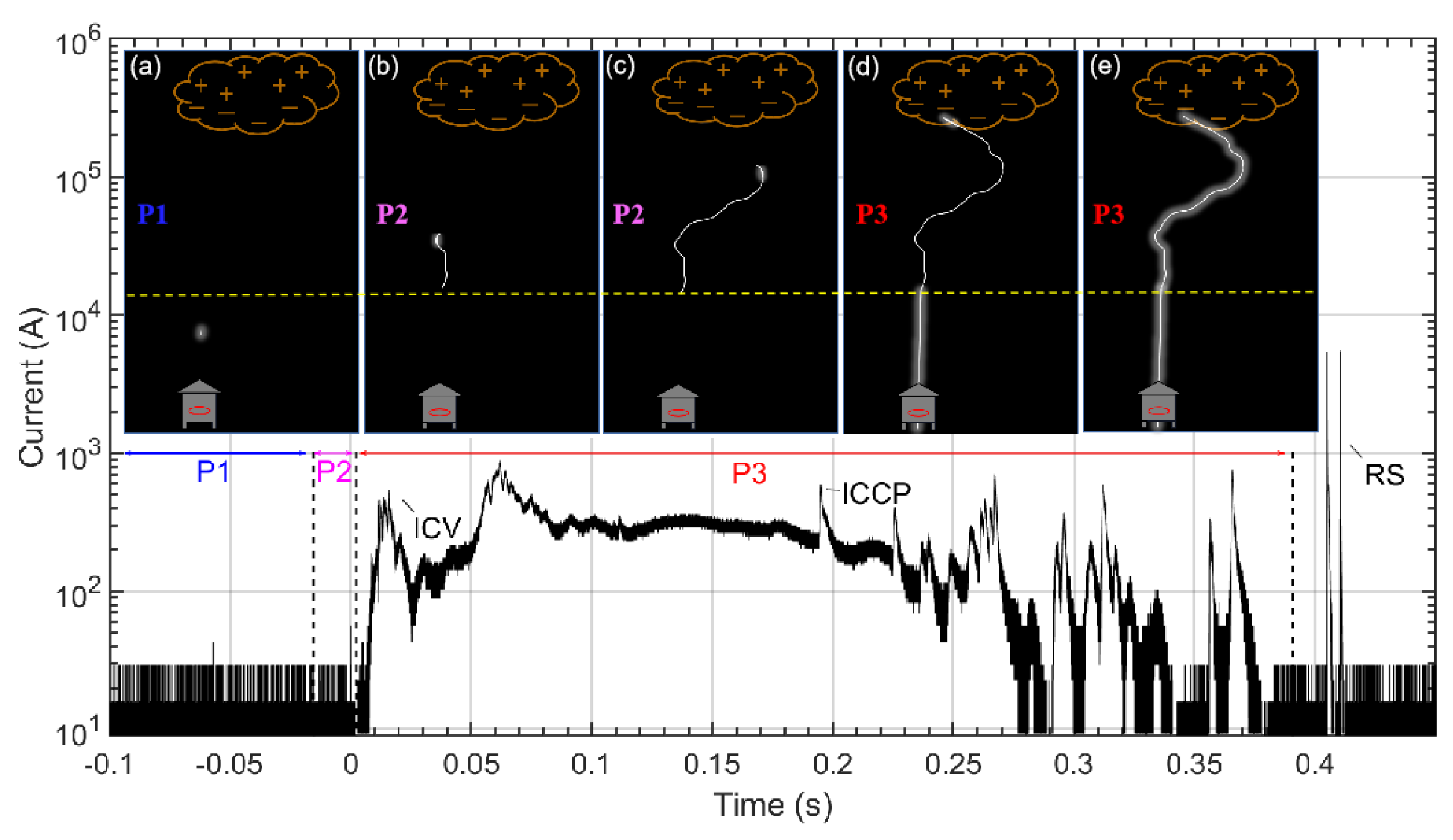
The schematic diagram for the development process of a negative rocket-triggered lightning flash at 0715:22 UTC on 2 July 2019 is shown in
Figure 4, which marks three phases of a channel-base current during the initial stage—P1, the current pulse before the sustained upward leader is called precursory phase with tens of attempted leader inception; P2, the positive leader that develops upward while producing impulsive current pulses, which is called the phase of initial current pulse (ICP); and P3, when the positive leader develops upward to certain height, the resulting continuous current is called initial continuous current (ICC), which includes the initial current variation (ICV) related to the disintegration of steel wire and initial continuous current pulse (ICCP) superimposed on the ICC [
3,
7]. The yellow dotted line in
Figure 4 is the altitude of leader inception, typically ranging from 150 to 350 m [
17].
In
Figure 4a, faint luminescent objects are occasionally observed at the precursory stage. After the appearance of a sustained upward leader,
Figure 4b shows the brightening of the leader head. In
Figure 4c, the initial current transmits downward along the wire during the continuous development of the upward positive leader. With the development of the upward leader and the increase of initial current, the rocket-tailing wire is fused in
Figure 4d, and the relatively dim lightning channel from the cloud to ground is established. In
Figure 4e, due to the transmission of substantial charge to the ground, the brightness of whole lightning channel is enhanced.
3.1. Magnetic Pulses at the Precursory Stage
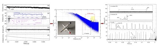
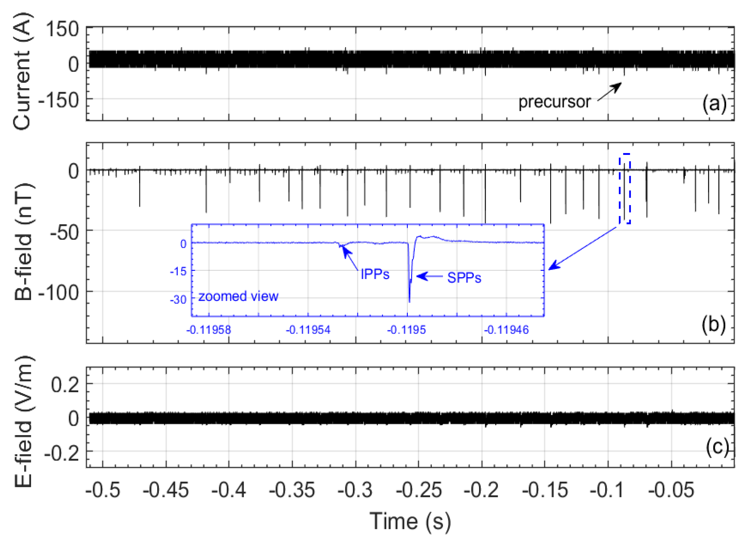
The channel-base current B-field at the close site and the E-field measured for the triggered lightning flash examined in this paper are shown in
Figure 5a–c, respectively. The duration of the precursory stage is approximately 0.5 s. Due to the incomplete data acquisition, the E-field signal at the far site is not shown in
Figure 5. There are a lot of precursor pulses marked in
Figure 5a. With the threshold of 0.1 nT (about twice background noise level), the magnetic pulses of the precursor are divided into initial precursor pulses (IPPs) and subsequent precursor pulses (SPPs), as indicated in
Figure 5b.
The results of statistical analyses on the B-field data are listed in
Table 1. The peak of IPPs ranges from 0.7 to 10.2 nT, and the mean is 2.1 nT; the peaks of SPPs are relatively larger than IPPs. The duration of IPPs and SPPs is similar, and the average is around 4.0 μs. The inter-pulse interval of IPPs varies from 0.8 to 8.9 ms, with an approximate mean of 4.0 ms. The inter-pulse interval of SPPs ranges from 8.1 to 25.7 ms, and the mean is 18.7 ms, which is much larger than IPPs. These observations are generally in accordance with previous reports [
1,
2,
12]. The charge accumulated at the tip of wire increases with the ascending rocket and wire. The corona streamers produce the precursors continuously, and the B-field characteristics of precursor pulses also change. The decreasing number of IPPs between isolated SPPs and the decreasing time interval between the occurrences of isolated SPPs indicate that SPPs steadily attempt to transform to UPL. When the accumulation of charge reaches a certain level, there will be a multi-pulse discharging process at the tip of the wire, which represents the inception of a sustained upward leader.
3.2. Magnetic Pulses at the ICP Stage
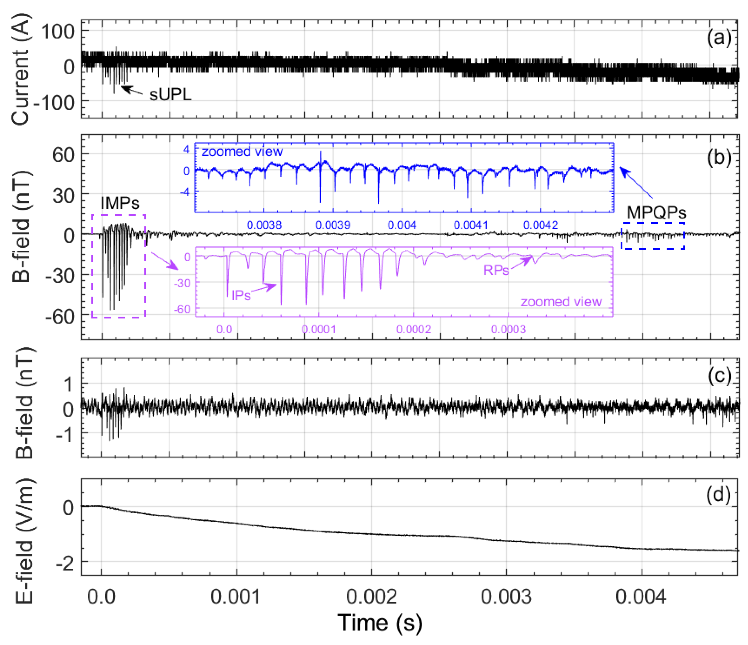
The duration of the ICP stage is about 0.05 s. There is a cluster of current pulses marked in
Figure 6a, which is called the sustained upward positive leader (sUPL), and the corresponding initial magnetic pulses (IMPs) are magnified in the inset of
Figure 6b, which contains impulsive pulses (IPs) and ripple pulses (RPs).
The initial magnetic pulses are radiated by the downward propagation of initial current pulses generated at the tip of steel wire along the wire [
27]. According to characteristics of magnetic pulses, the initial magnetic pulses can be divided into two types, IPs and RPs. Due to the development of a high-impedance channel [
6], IP transforms to RP due to the low-pass-filtering effect of the leader channel; the peak value of magnetic pulses is greatly reduced, and instead the duration increases significantly, as shown in
Table 2.
The magnetic pulses of quiet period (MPQPs) are also shown in a different inset of
Figure 6b. Although the B-field pulses after the initial pulses appear relatively quiet, the UPL develops steadily [
4,
28]. Due to the insufficient discharge intensity and attenuation of the leader channel, there are few magnetic pulses during the quiet stage as identified in previous observations. Due to the extension of magnetic sensor bandwidth to MF, MPQPs are discerned more clearly than in the previous experiment in GCOELD. According to the statistical results in
Table 2, the duration and inter-pulse interval of MPQPs is 1.4 and 13.4 μs, respectively, which is significantly lower than that of sUPL. In summary, the UPL continues developing during the quiet period, only propagating upward with a relatively small breakdown scale.
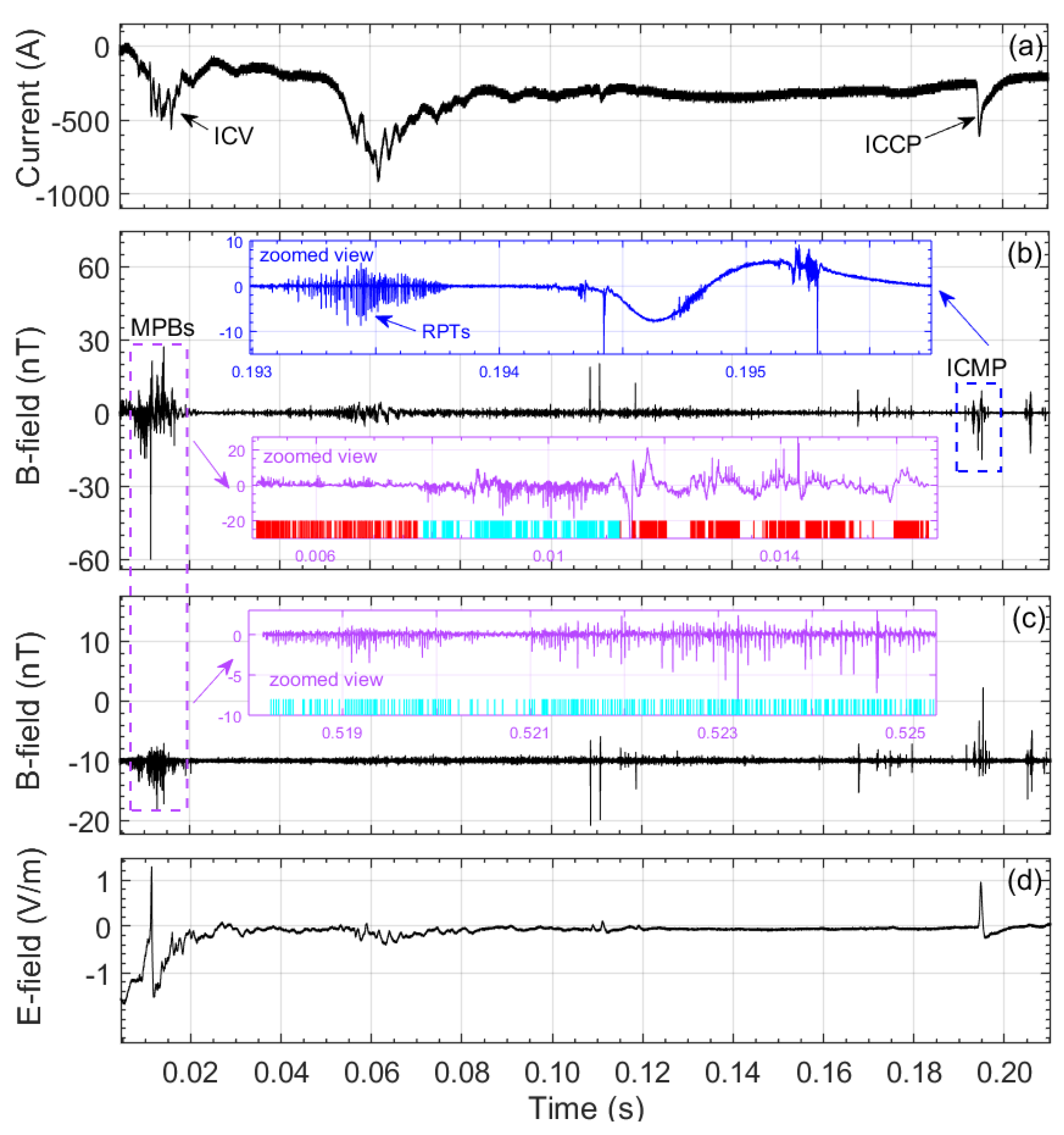
3.3. Magnetic Pulses at the ICC Stage
The waveform during the ICC stage is relatively complex. Usually, the ICV process related to the fusion of steel wire appears first, and then some pulses are often superimposed on the ICC waveform at the subsequent initial continuous current (ICC) stage, which are called the initial continuous current pulses (ICCPs).
At the ICV stage, the magnetic pulse burst (MPB) appears in both the close and far B-field, as shown in the purple zoomed view of
Figure 7. The duration and inter-pulse interval of MPBs are approximately 4.7 and 25.9 μs (see
Table 3), respectively. The statistical results are very similar to those of the upward leader in natural lightning [
29], which means that MPBs are likely related to the stepwise progression of the upward positive leader [
30,
31]. The superposition of radiation from two different sources causes the chaotic waveform of MPBs measured at the close site. The regular B-field pulses are produced by the breakdown at the leader head. The chaotic signals are the induced dB/dt signals when the ICC propagates downward first along the leader channel and then the steel wire. Due to the weakness of dB/dt signals and attenuation of the propagation path, these chaotic signals cannot be recorded at the far site, which only shows the features of regular pulses. In addition, the polarity of MPBs is also different at the close site and far site, as shown in the purple zoomed views.
The initial continuous magnetic pulses (ICMPs) show very intensive pulses features at the initial stage of ICCP, which are shown in the blue zoomed view of
Figure 7. Those intensive regular pulse trains (RPTs) correspond to the recoil leader process, which become the general form of lightning discharge in ICC [
32,
33]. After that, continuous current propagates down the leader channel and produces a slowly changing B-field. In addition, the slowly changing B-field is also superimposed with small magnetic pulses related to in-cloud discharges.
4. Discussions
In
Section 3, for different phases during initial upward leader development, we describe the characteristics of magnetic pulses measured with the improved magnetic sensor in a negative rocket-triggered lightning flash. Here, we further discuss the results by making a comparison between different types of pulses.
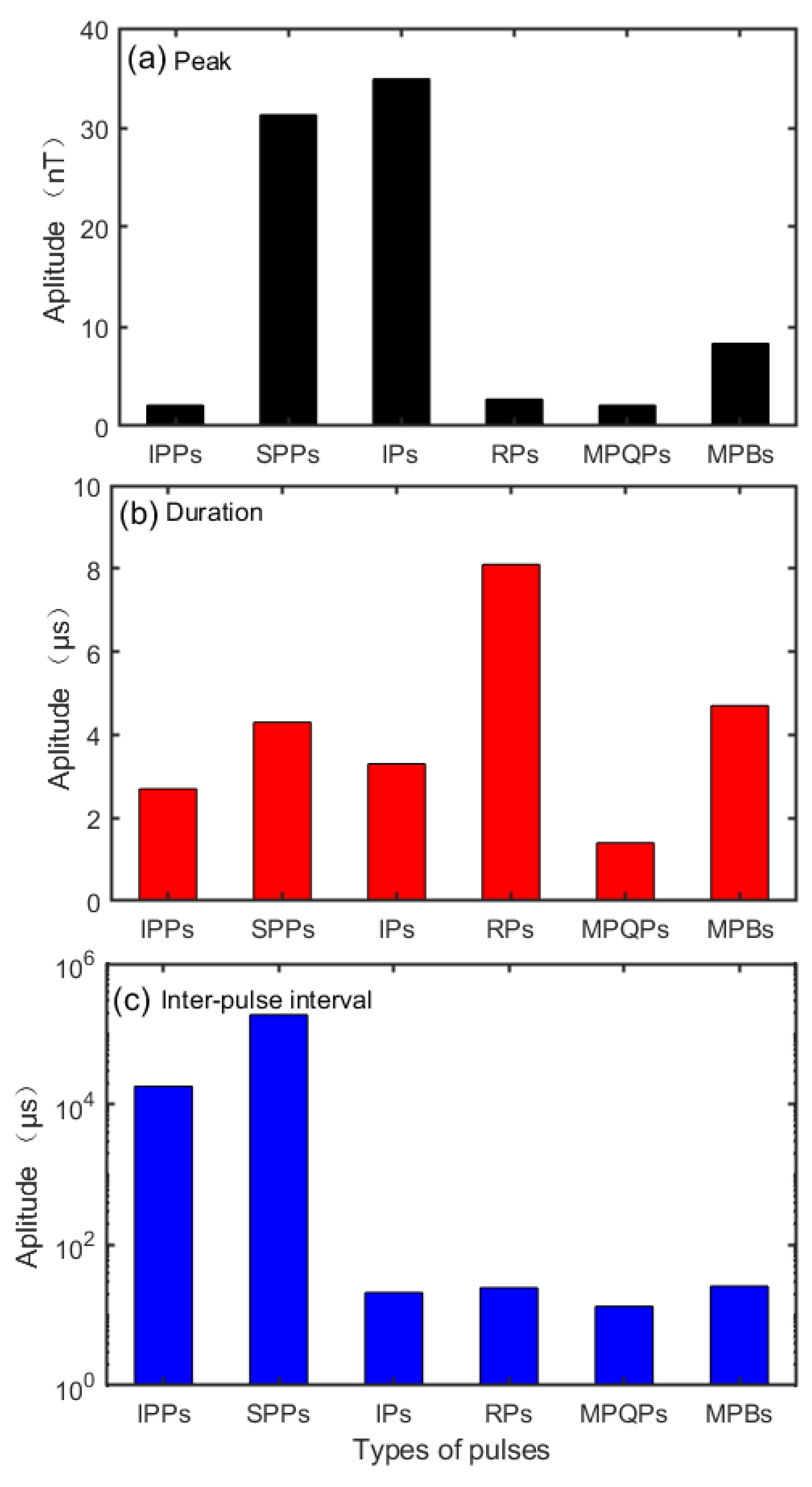
4.1. Comparison between Different Types of Magnetic Pulses during the Initial Stage
According to the different waveform characteristics mentioned above, the pulses at the initial stage are divided into six types, including—IPPs, SPPs, IPs, RPs, MPQPs, and MPBs. The results of the comparison of peak, duration and inter-pulse interval are shown in
Figure 8.
Zeng [
34] considered that the streamer discharge generates a cloud of free electrons and ions, which form a corona region under positive lightning impulse. On this basis, it is inferred that the streamer discharge is the same process as the transition from IPPs to SPPs. Due to the high impedance channel, IPs gradually transform into RPs. At this time, the peak of RPs decreases substantially, while the duration of RPs rises significantly; however, the inter-pulse interval does not change considerably. Due to the extension of the high-impedance channel, the peak of MPQPs decreases continuously, and the upward leader can only propagate upward by small-scale breakdown during the quiet period, so the duration and inter-pulse interval of MPQPs are the smallest among the various pulses. The MPBs at the close site actually contain the pulses generated by the breakdown of the upward leader and the slowly changing dB/dt signals, so the peak of MPBs is the largest after the leader inception.
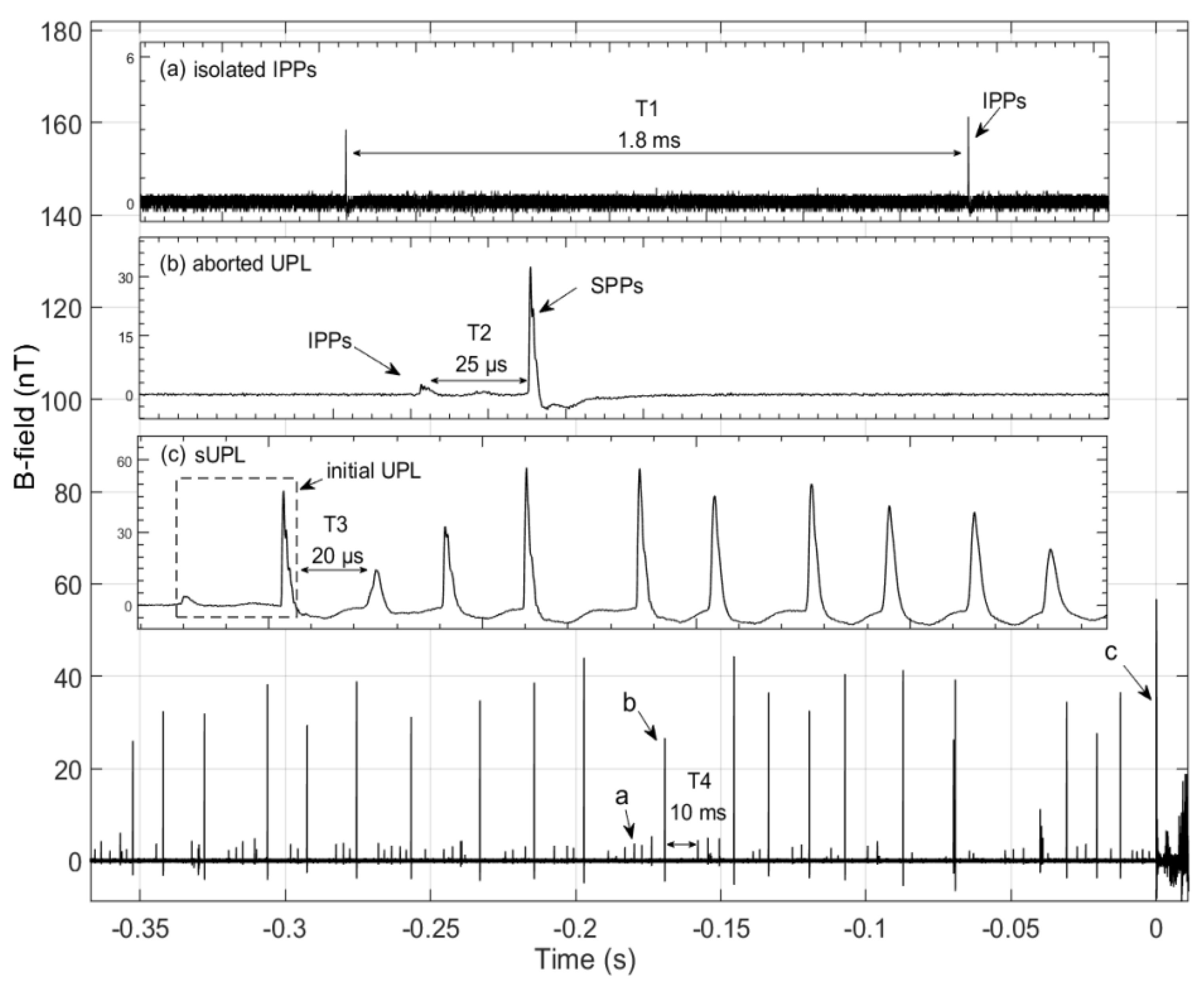
4.2. Transition from Precursor to sUPL
The crux of successfully triggering a lightning flash is the appearance of sUPL, which transforms from a precursor during the ascension of the rocket [
10,
11,
12]. There are isolated IPPs before the appearance of SPPs, and the inter-pulse interval of IPPs without being interrupted by SPPs is mostly stable at 1.8 ms (see T1 in
Figure 9a). It is noticed that all of the SPPs are preceded by an IPP, which occurs at about 25 μs (see T2 in
Figure 9b) prior to the SPPs. Before the appearance of sUPL (
Figure 9c), there are many aborted UPLs, as shown in
Figure 9. In the subsequent process, IPPs will develop into an aborted UPL or an initial UPL.
Due to the relatively large background noise of channel-base current measurement, the current signal cannot be well resolved (see
Figure 5a). Lu [
16] showed that there is a linear correlation between the peak value of a B-field pulse and current pulse at the initial stage. For the case examined in this paper, the current and transfer charge of IPPs are about 3.3 A and 4.2 μC, respectively, which are very similar to the results obtained in the laboratory [
34].
The characteristics of B-field pulses show that the pulse of last aborted UPL at the precursor stage is generally similar to the initial UPL, except for the short time without a noticeable discharging process (see T3 in
Figure 9, about 20 μs), and the relatively long quiet phase (see T4 in
Figure 9, about 10 ms) after the aborted UPL may be conducive to the stronger E-field. With the rocket and wire rapid ascending, there is a space charge region at the top of the wire, and the space charge has a certain shielding effect. If the E-field strength is not strong enough and the charge at the top of the wire cannot be quickly supplemented, the upward leader will be aborted [
35]. After going through the long quiet phase, the corona discharge becomes stronger with the continuous charge accumulation [
36], and the initial UPL occurs at the positive end of the ionized channel. The constantly supplementary potential causes the subsequent breakdown, which results in the formation of a sustained upward positive leader [
37,
38]. In summary, the transition from a precursor to sUPL is a natural process when the E-field is strong enough in the vicinity of the wire tip.
4.3. Comparison with the Studies of Natural Lightning
Artificially triggered lightning has the advantage of a controlled location, a predictable time of occurrence and the ability to obtain direct current measurements, and it has become an important tool in the study of natural lightning. By benefiting from the abundance of observation devices and the improvement of technology, scholars are continuing to reveal details of the physical processes of lightning.
There have been a great amount of studies on the mechanism of lightning initiation. Phelps [
39] found that positive streamers played a key role in lightning initiation. The propagation of positive streamers in a region of uniform
E-field requires the applied
E-field to be greater than the minimum value required to enable the streamers to bridge the gap between electrodes. Petersen [
40] presented a hypothetical mechanism of lightning initiation that the initial lightning leader might form by the space leader observed in the laboratory. The positive streamer system is triggered by the loss-of-control breakdown and the hydro-meteorite acts as a local reinforcement of the
E-field, followed by the formation of the initial lightning leader channel, which is similar to the formation of the space leader in the laboratory. Comparing the previous studies with the findings of this paper, it is suggested that the same transition mechanism from precursor to sUPL is present in natural lightning.
In summary, the signals detected by the improved magnetic sensor will provide an important reference for us to characterize natural lightning pulses and their development mechanisms. Considering the manufacturing technology and cost of densely wound coils, the upper bound frequency of the sensor is extended to 1.2 MHz in this experiment. In the future, our research team will improve the performance of the magnetic field sensor to investigate more details about the physical process during the rocket-triggered lightning experiment.
5. Conclusions
In this paper, we present the results of analyses on the radio-frequency magnetic radiation during the upward leader progression of a negative rocket-triggered lightning flash at 0715:22 UTC on 2 July 2019. In order to get more insight into the stepwise propagation of upward leader in triggered lightning, the bandwidth of a radio-frequency magnetic sensor was extended to 20 kHz–1.2 MHz, which could be used to measure the medium-frequency signals that cannot be readily detected by the LF magnetic sensor used in our previous measurements.
Aided by the extension of the bandwidth of the magnetic sensor, it is found that the process from IPPs to SPPs was the same as the breakdown in the streamer discharge, which were very similar to the results obtained in the laboratory. In the subsequent process, IPPs will be developed into aborted UPL or initial UPL, so the transition from precursor to sUPL was a natural process when the electric field was strong enough ahead of the wire tip. By analyzing the signals captured with the improved sensor, MPQPs are discerned more clearly than the previous experiments in GCOELD, and MPQPs can only propagate upward by small-scale breakdown. It also benefited from the expansion of B-field bandwidth, as the improved sensors at the far site detected MPBs which could only be found at the close site in a previous experiment.
As mentioned above, there are significant differences in the polarity of MPBs between the far site and close site, and we will conduct short-baseline very-high-frequency (VHF) mapping observations for further research. In addition, due to the measurement advantages of the improved sensor in the low-frequency and medium-frequency bandwidth, the LF-MF sensor in this paper can be used for lightning localization studies in the future.
Author Contributions
Conceptualization, T.S. and G.L.; methodology, T.S. and G.L.; software, T.S. and Y.F.; validation, T.S. and X.L.; formal analysis, T.S.; investigation, T.S. and Y.Z.; resources, T.S.; data curation, T.S. and Y.Z.; writing—original draft preparation, T.S. and G.L.; writing—review and editing, T.S. and G.L. All authors have read and agreed to the published version of the manuscript.
Funding
This research was funded by National Key R&D Program of China (2017YFC1501501), Natural Science Foundation of Excellent Youth Program of China (41622501), and National Natural Science Foundation of China (41875006, U1938115).
Institutional Review Board Statement
Not applicable.
Informed Consent Statement
Not applicable.
Data Availability Statement
Data sharing is not applicable to this article.
Acknowledgments
The authors would like to thank the Lightning Research Group of State Key Laboratory of Severe Weather, Chinese Academy of Meteorological Sciences for providing the data.
Conflicts of Interest
The authors declare no conflict of interest.
Abbreviations
List of abbreviations used in the paper:
| LF-MF | low-frequency and medium-frequency |
| E-field | electric field |
| B-field | magnetic field |
| SHATLE | SHandong Triggering Lightning Experiment |
| GCOELD | Guangdong Comprehensive Observation Experiment on Lightning Discharge |
| MPB | magnetic pulse burst |
| ICC | initial continuous current |
| ICP | initial current pulse |
| IMP | initial magnetic pulse |
| ICV | initial current variation |
| ICCP | initial continuous current pulse |
| ICMP | initial continuous magnetic pulse |
| IPP | initial precursor pulse |
| SPP | subsequent precursor pulse |
| sUPL | sustained upward positive leader |
| IP | impulsive pulse |
| RP | ripple pulse |
| MPQP | magnetic pulse of quiet period |
| RPT | regular pulse train |
| RP | ripple pulse |
| MPQP | magnetic pulse of quiet period |
| VHF | very-high-frequency |
References
- Biagi, C.J.; Uman, M.A.; Hill, J.D.; Jordan, D.M.; Rakov, V.A.; Dwyer, J. Observations of stepping mechanisms in a rocket-and-wire triggered lightning flash. J. Geophys. Res. 2010, 115, 599. [Google Scholar] [CrossRef]
- Biagi, C.J.; Uman, M.A.; Hill, J.D.; Rakov, V.A.; Jordan, D.M. Transient current pulses in rocket-extended wires used to trigger lightning. J. Geophys. Res. 2012, 117. [Google Scholar] [CrossRef]
- Qie, X.; Yang, J.; Jiang, R.; Wang, J.; Liu, D. A New-Model Rocket for Artificially Triggering Lightning and Its First Triggering Lightning Experiment. Chin. J. Atmos. Sci. 2010, 34, 937–946. [Google Scholar]
- Zhang, Y.; Yang, S.; Lu, W.; Zheng, D.; Dong, W.; Li, B. Experiments of artificially triggered lightning and its application in Conghua, Guangdong, China. Atmos. Res. 2014, 135–136, 330–343. [Google Scholar] [CrossRef]
- Fisher, R.J.; Schnetzer, G.H.; Thottappillil, R.; Rakov, V.A.; Uman, M.A.; Goldberg, J.D. Parameters of triggered-lightning flashes in Florida and Alabama. J. Geophys. Res. 1993, 98, 22887–22902. [Google Scholar] [CrossRef]
- Rakov, V.A.; Uman, M.A.; Rambo, K.J.; Fernandez, M.I.; Fisher, R.J.; Schnetzer, G.H.; Thottappillil, R.; Eybert-Berard, A.; Berlandis, J.P.; Lalande, P. New insights into lightning processes gained from triggered-lightning experiments in Florida and Alabama. J. Geophys. Res. 1998, 1031, 14117–14130. [Google Scholar] [CrossRef] [Green Version]
- Wang, D.; Rakov, V.A.; Uman, M.A.; Fernandez, M.I.; Rambo, K.J.; Schnetzer, G.H.; Fisher, R.J. Characterization of the initial stage of negative rocket-triggered lightning. Geophys. Res. Atmos. 1999, 104, 4213–4222. [Google Scholar] [CrossRef]
- Qie, X.; Jiang, R.; Yang, J. Characteristicsofcurrentpulsesinrocket-triggeredlightning. Atmos. Res. 2014, 135–136, 322–329. [Google Scholar] [CrossRef]
- Biagi, C.J.; Uman, M.A.; Hill, J.D.; Jordan, D.M. Observations of the initial, upward-propagating, positive leader steps in a rocket-and-wire triggered lightning discharge. Geophys. Res. Lett. 2011, 38. [Google Scholar] [CrossRef] [Green Version]
- Horii, K. Experiment of artificial lightning triggered with rocket. Mem. Fac. Eng. Nagoya Univ. 1982, 34, 77–112. [Google Scholar]
- Lalande, P.; Bondiou-Clergerie, A.; Laroche, P.; Eybert-Berard, A.; Berlandis, J.P.; Bador, B. Leader properties determined with triggered lightning techniques. J. Geophys. Res. 1998, 103, 14109. [Google Scholar] [CrossRef]
- Willett, J.C.; Davis, D.A.; Laroche, P. An experimental study of positive leaders initiating rocket-triggered lightning. Atmos. Res. 1999, 51, 189–219. [Google Scholar] [CrossRef]
- Zhang, Y.; Zhou, X. Review and Progress of Lightning Research. J. Appl. Meteorol. 2006, 17, 829–834. [Google Scholar] [CrossRef]
- Rakov, V.A.; Crawford, D.E.; Kodali, V.; Idone, V.P.; Uman, M.A.; Schnetzer, G.H. Cutoff and reestablishment of current in rocket-triggered lightning. J. Geophys. Res. Atmos. 2003, 108. [Google Scholar] [CrossRef] [Green Version]
- Rakov, V.A. Some inferences on the propagation mechanisms of dart leaders and return strokes. J. Geophys. Res. Atmos. 1998, 103, 1879–1887. [Google Scholar] [CrossRef]
- Lu, G.; Zhang, H.; Jiang, R.; Fan, Y.; Qie, X.; Liu, M.; Sun, Z.; Wang, Z.; Tian, Y.; Liu, K. Characterization of initial current pulses in negative rocket-triggered lightning with sensitive magnetic sensor. Radio Sci. 2016, 51. [Google Scholar] [CrossRef]
- Jiang, R.; Qie, X.; Wang, C.; Yang, J. Propagating features of upward positive leaders in the initial stage of rocket-triggered lightning. Atmos. Res. 2013, 129, 90–96. [Google Scholar] [CrossRef]
- Ngin, T.; Uman, M.A.; Hill, J.D.; Pilkey, J.; Gamerota, W.R.; Jordan, D.M.; Olsen, R.C. Measurement and analysis of ground-level electric fields and wire-base current during the rocket-and-wire lightning triggering process. J. Geophys. Res. Atmos. 2013, 118, 10041–10055. [Google Scholar] [CrossRef]
- Shao, X.; Rhodes, C.T.; Holden, D.N. RF radiation observations of positive cloud-to-ground flashes. J. Geophys. Res. Atmos. 1999, 104. [Google Scholar] [CrossRef]
- Lu, G.; Fan, Y.; Jiang, R.; Zhang, H.; Liu, M.; Qie, X.; Cummer, S.A.; Liu, K. Measurement of continuing charge transfer in rocket-triggered lightning with low-frequency magnetic sensor at close range. J. Atmos. Sol. Terr. Phys. 2018, 143–144, 88–101. [Google Scholar] [CrossRef]
- Fan, Y.; Lu, G.; Jiang, R.; Zhang, H.; Liu, M.; Qie, X. Application of low-frequency magnetic sensor for remote measurement of the initial continuous current in rocket-triggering lightning. Chin. J. Atmos. Sci. 2017, 41, 1027–1036. [Google Scholar] [CrossRef]
- Fan, Y.; Lu, G.; Zhang, Y.; Lv, W.; Zheng, D.; Fan, X. Characteristics of Medium-low Frequency Magnetic Fields of Initial Continuous Current in Rocket-triggered Lightning. J. Appl. Meteorol. Sci. 2020, 31, 213–223. [Google Scholar] [CrossRef]
- Zheng, D.; Zhang, Y.; Lu, W.; Zhang, Y.; Dong, W.; Chen, S.; Dan, J. Characteristics of return stroke currents of classical and altitude triggered lightning in GCOELD in China. Atmos. Res. 2013, 129, 67–68. [Google Scholar] [CrossRef]
- Tumanski, S. Induction coil sensors-a review. Meas. Sci. Technol. 2007, 18, R31–R46. [Google Scholar] [CrossRef]
- Pathak, P.P.; Rai, P.P.; Varshneya, N.C. VLF radiation from lightning. Geophys. J. R. Astron. 2010, 69, 197–207. [Google Scholar] [CrossRef] [Green Version]
- NaitAmor, S.; AlAbdoadaim, M.A.; Cohen, M.B.; Cotts, B.R.T.; Soula, S.; Chanrion, O.; Neubert, T.; Abdelatif, T. VLF observations of ionospheric disturbances in association with TLEs from the EuroSprite-2007 campaign. J. Geophys. Res. Space Phys. 2010, 115, A00E47. [Google Scholar] [CrossRef] [Green Version]
- Fan, Y.; Lu, G.; Zhang, H.; Jiang, R.; Li, X.; Liu, M.; Qie, X.; Zheng, D.; Zhang, Y.; Lu, W.; et al. Characteristics of electromagnetic signals during the initial stage of rocket-triggered lightning. J. Geophys. Res. Atmos. 2018. [Google Scholar] [CrossRef]
- Sun, Z.; Qie, X.; Jiang, R.; Liu, M.; Wu, X.; Wang, Z.; Lu, G.; Zhang, H. Characteristics of a rocket-triggered lightning flash with large stroke number and the associated leader propagation. J. Geophys. Res. Atmos. 2014, 119, 13388–13399. [Google Scholar] [CrossRef]
- Cooray, V.; Lundquist, S. On the characteristics of some radiation fields from lightning and their possible origin in positive ground flashes. J. Geophys. Res. 1982, 871, 11203–11214. [Google Scholar] [CrossRef]
- Lu, G.; Jiang, R.; Qie, X.; Zhang, H.; Sun, Z.; Liu, M.; Wang, Z.; Liu, K. Burst of intracloud current pulses during the initial continuous current of a rocket-triggered lightning flash. Geophys. Res. Lett. 2014, 41. [Google Scholar] [CrossRef]
- Fan, Y.; Lu, G.; Li, X.; Zhang, H.; Jiang, R.; Liu, M.; Qie, X.; Zhang, Y.; Zhang, Y.; Lu, W.; et al. Measurements of burst of magnetic pulses during the initial continuous current in rocket-triggered lightning. J. Geophys. Res. Atmos. 2019. [Google Scholar] [CrossRef]
- Ogawa, T.; Brook, M. The mechanism of the intracloud lightning discharge. J. Geophys. Res. 1962, 69, 5145–5150. [Google Scholar] [CrossRef]
- Mazur, V.; Ruhnke, L.; Warner, T.; Orville, R. Recoil leader formation and development. J. Electrost. 2013, 71, 763–768. [Google Scholar] [CrossRef] [Green Version]
- Zeng, R.; Zhuang, C.; Yu, Z.; Li, Z.; Geng, Y. Electric field step in air gap streamer discharge. Appl. Phys. Lett. 2011, 99, 221503-1–221503-3. [Google Scholar] [CrossRef]
- Zhang, Y.; Qian, Y.; Zhang, Y.; Lu, W.; Zheng, D.; Chen, S. Discharge Characteristics of Upward Positive Leaders in Initial Stage of Artificially Triggered Lightning. High Volt. Eng. 2017, 43, 1602–1608. [Google Scholar] [CrossRef]
- Liu, N.; Kosar, B.; Sadighi, S.; Dwyer, J.; Rassoul, H. Formation of streamer discharges from an isolated ionization column at sub-breakdown conditions. Phys. Rev. Lett. 2012, 109, 025002. [Google Scholar] [CrossRef] [Green Version]
- Becerra, M. Glow corona generation and streamer inception at the tip of grounded objects during thunderstorms: Revisited. J. Phys. D Appl. Phys. 2013, 46, 135205. [Google Scholar] [CrossRef]
- Liu, L.; Becerra, M. On the critical charge required for positive leader inception in long air gaps. J. Phys. D Appl. Phys. 2018, 51, 35202. [Google Scholar] [CrossRef]
- Phelps, C.T. Positive streamer system intensification and its possible role in lightning initiation. J. Atmos. Terr. Phys. 1974, 36, 103–111. [Google Scholar] [CrossRef]
- Petersen, D.; Bailey, M.; Beasley, W.H.; Hallett, J. A brief review of the problem of lightning initiation and a hypothesis of initial lightning leader formation. J. Geophys. Res. Atmos. 2008, 113. [Google Scholar] [CrossRef]
Figure 1.
Schematic diagram on initial process of triggering lightning with wired rocket during the triggered lightning experiment of Field Experiment Base on Lightning Sciences, China Meteorological Administration (CMA-FEBLS).
Figure 1.
Schematic diagram on initial process of triggering lightning with wired rocket during the triggered lightning experiment of Field Experiment Base on Lightning Sciences, China Meteorological Administration (CMA-FEBLS).
Figure 2.
Channel-base current waveform (a) and power spectrum analysis (b).
Figure 2.
Channel-base current waveform (a) and power spectrum analysis (b).
Figure 3.
Fourier transform of channel-base current measured from the shunt and improved magnetic sensor.
Figure 3.
Fourier transform of channel-base current measured from the shunt and improved magnetic sensor.
Figure 4.
Schematic diagram for the division of the channel-base current and development process of a negative rocket-triggered lightning flash at 0715:22 UTC on 2 July 2019.
Figure 4.
Schematic diagram for the division of the channel-base current and development process of a negative rocket-triggered lightning flash at 0715:22 UTC on 2 July 2019.
Figure 5.
Simultaneous measurements during the precursor stage of a negative rocket-triggered lightning flash at 0715: 22 UTC on 2 July 2019, (a) channel-base current waveform, (b) B-field signals at the close site, (c) fast E-field signals at the close site.
Figure 5.
Simultaneous measurements during the precursor stage of a negative rocket-triggered lightning flash at 0715: 22 UTC on 2 July 2019, (a) channel-base current waveform, (b) B-field signals at the close site, (c) fast E-field signals at the close site.
Figure 6.
Simultaneous measurements during the initial current pulse (ICP) stage of a negative rocket-triggered lightning flash at 0715:22 UTC on 2 July 2019, (a) channel-base current waveform, (b) B-field signals at the close site, (c) B-field signals at the far site and (d) fast E-field signals at the close site.
Figure 7.
Simultaneous measurements during the initial continuous current (ICC) stage of a negative rocket-triggered lightning flash at 0715: 22 UTC on 2 July 2019, and the red and blue short lines indicate the positive and negative polarity of the B-field pulse, respectively. (a) Channel-base current waveform, (b) B-field signals at the close site, (c) B-field signals at the far site and (d) fast E-field signals at the close site.
Figure 8.
Characteristics of different types of magnetic pulses. (a) Peak, (b) Duration, (c) Inter-pulse interval. IPPs, initial precursor pulses; SPPs, subsequent precursor pulses; IPs, impulsive pulses; RPs, ripple pulses; MPQPs, magnetic pulses of quiet period; MPBs, magnetic pulses burst.
Figure 8.
Characteristics of different types of magnetic pulses. (a) Peak, (b) Duration, (c) Inter-pulse interval. IPPs, initial precursor pulses; SPPs, subsequent precursor pulses; IPs, impulsive pulses; RPs, ripple pulses; MPQPs, magnetic pulses of quiet period; MPBs, magnetic pulses burst.
Figure 9.
B-field waveform during transition from a precursor to sUPL of a negative rocket-triggered lightning flash at 0715: 22 UTC on 2 July 2019. (a) Individual IPPs, (b) magnetic pulses of aborted UPL, (c) magnetic pulses of sUPL.
Figure 9.
B-field waveform during transition from a precursor to sUPL of a negative rocket-triggered lightning flash at 0715: 22 UTC on 2 July 2019. (a) Individual IPPs, (b) magnetic pulses of aborted UPL, (c) magnetic pulses of sUPL.
Table 1.
Characteristics of magnetic pulses during the precursor stage.
Table 1.
Characteristics of magnetic pulses during the precursor stage.
| Stage | Parameter | Mean | Median | Max | Min |
|---|
| IPPs | Peak (nT) | 2.1 | 1.9 | 10.2 | 0.7 |
| Duration (μs) | 3.7 | 2.8 | 20.4 | 0.8 |
| Inter-pulse interval (ms) | 1.8 | 1.0 | 8.9 | 0.8 |
| SPPs | Peak (nT) | 31.3 | 30.5 | 44.3 | 17.5 |
| Duration (μs) | 4.3 | 3.2 | 30.4 | 1.5 |
| Inter-pulse interval (ms) | 18.7 | 16.3 | 25.7 | 8.1 |
Table 2.
Characteristics of magnetic pulses during the ICP stage.
Table 2.
Characteristics of magnetic pulses during the ICP stage.
| Stage | Parameter | Mean | Median | Max | Min |
|---|
| IPs | Peak (nT) | 34.9 | 39.7 | 56.733 | 10.733 |
| Duration (μs) | 3.3 | 3.1 | 5.9 | 0.9 |
| Inter-pulse interval (μs) | 21.1 | 19.8 | 28.8 | 16.2 |
| RPs | Peak (nT) | 2.7 | 1.9 | 9.0 | 0.7 |
| Duration (μs) | 8.1 | 8.4 | 12.1 | 2.2 |
| Interval (μs) | 24.7 | 21.7 | 45.3 | 13.8 |
| MPQPs | Peak (nT) | 2.1 | 1.7 | 6.5 | 0.7 |
| Duration (μs) | 1.4 | 1.1 | 2.5 | 0.2 |
| Inter-pulse interval (μs) | 13.4 | 12.2 | 20.5 | 5.7 |
Table 3.
Characteristics of magnetic pulses during the ICC stage.
Table 3.
Characteristics of magnetic pulses during the ICC stage.
| Stage | Parameter | Mean | Median | Max | Min |
|---|
| MPBs | Peak (nT) | 8.3 | 9.2 | 18.3 | 0.7 |
| Duration (μs) | 4.7 | 4.1 | 17.3 | 0.8 |
| Inter-pulse interval (μs) | 25.9 | 23.6 | 235 | 4.1 |
| Publisher’s Note: MDPI stays neutral with regard to jurisdictional claims in published maps and institutional affiliations. |
© 2021 by the authors. Licensee MDPI, Basel, Switzerland. This article is an open access article distributed under the terms and conditions of the Creative Commons Attribution (CC BY) license (https://creativecommons.org/licenses/by/4.0/).


