Technical Note

Research on Detection Technology of Spoofing under the Mixed Narrowband and Spoofing Interference

1
College of Electronic Science and Technology, National University of Defense Technology, Changsha 410073, China
2
Beijing BDStar Navigation Co., Ltd., Beijing 100080, China
*
Author to whom correspondence should be addressed.
Remote Sens. 2022, 14(10), 2506; https://0-doi-org.brum.beds.ac.uk/10.3390/rs14102506
Submission received: 10 April 2022 / Revised: 4 May 2022 / Accepted: 20 May 2022 / Published: 23 May 2022
(This article belongs to the Topic GNSS Measurement Technique in Aerial Navigation)

Abstract

:
The global navigation satellite system has achieved great success in the civil and military fields and is an important resource for space-time information services. However, spoof interference has always been one of the main threats to the application security of satellite navigation receivers. In order to further improve the application security of satellite navigation receivers, this paper focuses on the application scenarios where narrowband and spoofing interference exist at the same time, studies the problem of spoofing interference detection under mixed interference conditions, then proposes a spoofing interference detection method based on the tracking loop identification curve. This method can effectively deal with the detection of spoofing interference under the conditions of narrowband interference and, at the same time, it can effectively detect the spoofing interference of gradual deviation. Simulation experiments verify the effectiveness of the spoofing interference detection method, based on the tracking loop discrimination curve. In typical jamming and spoofing scenarios, when the spoofing signal is about 7.5 m away from the real signal, the method used in this paper can achieve effective detection. The proposed detection method is of great significance for improving the anti-spoofing capability of satellite navigation receivers.

Graphical Abstract

1. Introduction

The global navigation satellite system (GNSS) is the core infrastructure for providing spatiotemporal information services; it plays an irreplaceable role in all aspects of human activities [1,2]. From the financial system, power system, communication system, transportation, agriculture, forestry and fishery, hydrological monitoring, meteorological forecasting, disaster relief and mitigation, public safety, smart wear, etc., in the civilian realm to the military one, for the individual soldier, mobile combat platforms, and weapons guidance systems. It can be argued that satellite navigation systems and application terminals play an important and even core role [3,4,5,6]. Its all-time, all-weather, high-precision, low-cost, and other characteristics make it an important choice for navigation and timing tasks [7,8,9]. All major satellite navigation systems are in the process of continuous upgrading and continuous development, improving their performance of spatiotemporal information services in terms of accuracy, integrity, continuity, and availability in different application scenarios [10,11,12].
However, since the format of civil satellite navigation signals is an open one, it is not difficult for unofficial organizations and unauthorized individuals to forge and generate civil satellite navigation signals [13,14,15]. Authorized signals where the signal format is not disclosed can be forged by forwarding, and the power of the satellite navigation signals is weak when they reach the surface. By suppressing interference, deceiving interference, etc., an attacker can reduce or destroy satellite navigation without spending too much money [16,17,18]. Among the interference methods adopted by the attacker, the transmission power is lower than the suppression interference; therefore, the attack method must be more subtle. Deception interference is a greater threat and has more serious consequences, so the legitimate user needs to take strict precautions against it by reducing or even avoiding the threat of spoofing interference [19,20,21]. To combat the major threat of deception interference against satellite navigation applications, deception confrontation has always been a research hotspot in the field of satellite navigation in terms of fierce confrontation game scenarios and the pursuit of high-security and high-reliability spatiotemporal information services [22,23,24,25].
The purpose of spoofing interference detection is to identify the presence or absence of spoofing interference. When spoofing interference is detected, the use of GNSS signals can be stopped, which can effectively avoid actions being induced by false signals and resulting in more serious consequences [26,27]. Under normal circumstances, there is only one correlation peak in the signal search range, but when there is a spoofing signal, multiple correlation peaks may appear [28,29]. Therefore, the detection of spoofing interference can be performed using the number of correlation peaks. Existing satellite navigation receivers usually have the ability to resist narrowband interference; the suppression of narrowband interference is based on the time-frequency domain method. The interference is suppressed by the spectrum difference between the interference and the signal. This difference causes signal distortion, mainly manifesting as an elevation of the correlation peak sidelobes [30,31]. Therefore, when narrowband and spoofing interferences coexist, after narrowband interference is suppressed, the rise of the correlation peak sidelobes will trigger the spoofing jamming detection method, based on the number of correlation peaks to fail.
This paper proposes a spoofing interference detection method based on the tracking loop discrimination curve, to monitor the symmetry of the correlation peak. Even in the case of narrowband interference, the correlation peak is distorted but its symmetry remains unchanged. This method can deal efficiently with the detection of spoofing interference under the conditions of narrowband interference, and at the same time, it can effectively detect the spoofing interference of gradual biasing.
This paper is organized as follows. In Section 2, a mathematical model for narrowband interference suppression and correlation peak-based spoof interference detection is presented. Section 3 analyzes the impact of a spoofing interference detection method, based on the detection of the number of correlation peaks under narrowband interference conditions. Section 4 proposes a spoofing interference detection method, based on the tracking loop discrimination curve. In Section 5, simulation experiments are carried out. Finally, Section 6 discusses our findings, and our conclusions are given in Section 7.

2. Mathematics Model

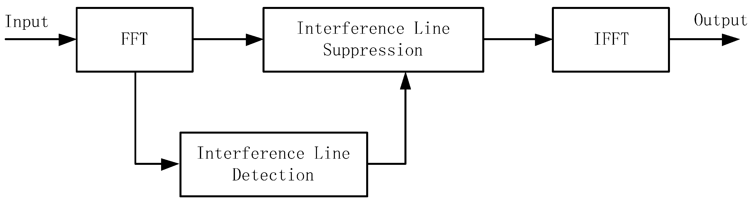
2.1. Narrowband Interference Suppression

The architecture of a single-antenna satellite navigation receiver is shown in Figure 1. In single-antenna receivers, the time-domain and frequency-domain anti-jamming algorithms are the most widely used algorithms. Compared with the time domain anti-jamming algorithm, the frequency domain anti-jamming algorithm has the following advantages: it can suppress multiple single-frequency interferences at the same time; when the interference bandwidth is greater than 5%, the frequency domain anti-jamming algorithm has better performance; when the quantization word length is sufficient, the dynamic range is large; the principle is simple, and a mature fast Fourier transform (FFT) algorithm can be used, which is easy to implement in engineering; the algorithm has good adaptive ability for data segmentation processing. For these reasons, the frequency domain anti-jamming algorithm is the most commonly used anti-jamming algorithm in engineering, and this paper takes the frequency domain anti-jamming algorithm as the research object [32,33,34].
Frequency domain anti-jamming is a common processing method for satellite navigation receivers. The received data is converted to the frequency domain through FFT; the interference spectrum is identified and suppressed, then converted from the frequency domain to the time domain through an inverse fast Fourier transform (IFFT) [35]. A block diagram of the basic principle of frequency domain anti-jamming is shown in Figure 2.
The spectra before and after anti-jamming in the frequency domain are shown in Figure 3. The suppression of narrowband interference is realized by setting the interference spectral line to zero.

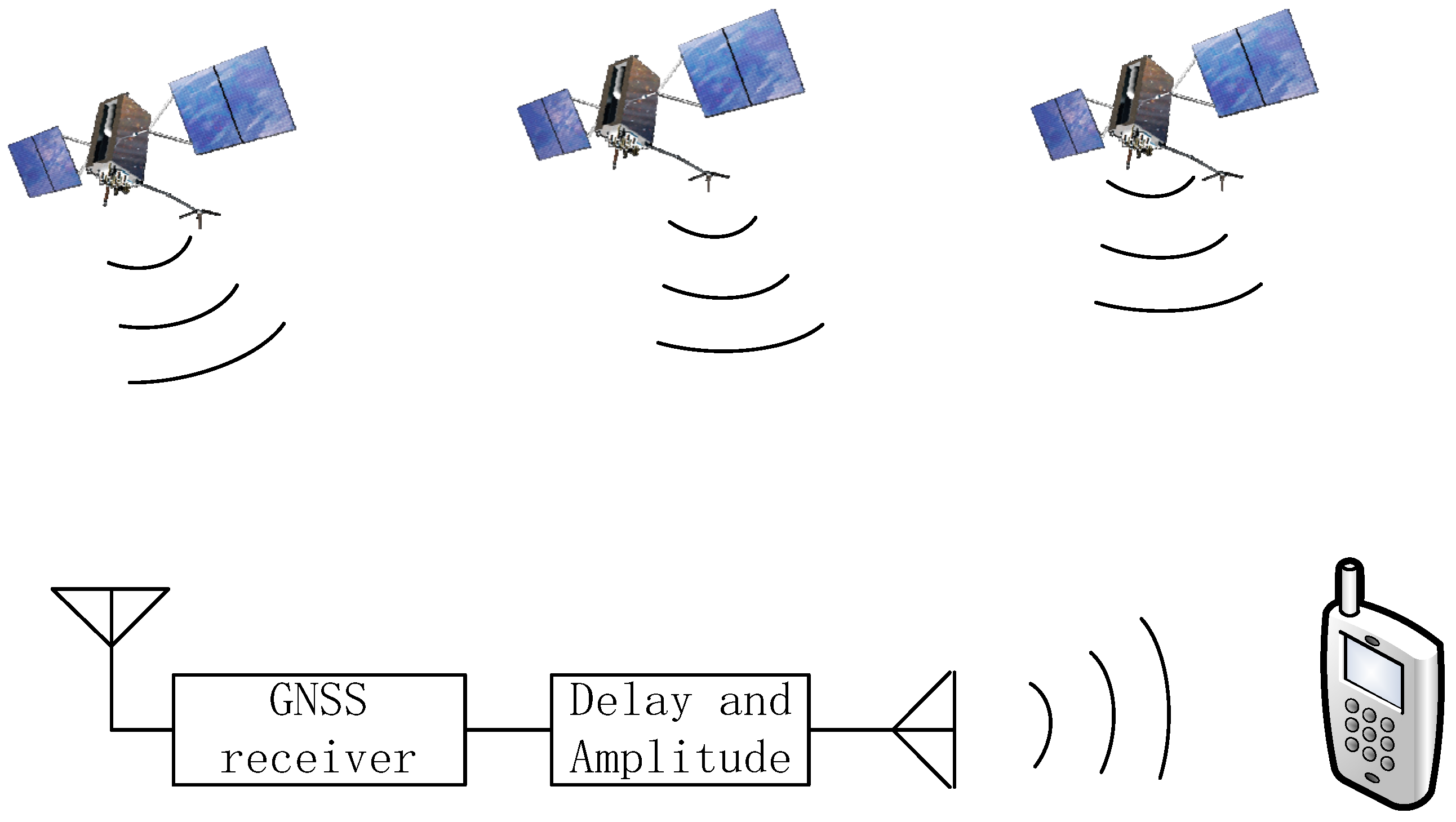
2.2. Spoofing Jamming Detection

Correlation peak detection technology is effective for both generatedand forwarding spoofing interference. This paper takes forwarding spoofing interference as an example for analysis. Relay deception interference works by first receiving the real GNSS signal, then transmitting it after a certain delay and amplification, so as to deceive the target GNSS receiver. These forwarded navigation signals are called spoofing signals. Compared with real signals, spoofing signals only differ in terms of delay and power and do not change the navigation text [36]. In order for the relay-type spoofing interference to successfully enter the GNSS receiver acquisition stage, the spoofing party usually increases the power of the spoofing signal to a level higher than that of the real satellite signal [37]. Therefore, GNSS receivers without any anti-spoofing measures are easily spoofed by repeater jammers. After the target GNSS receiver captures the relayed spoofing interference signal, it will calculate the wrong pseudo-range and cannot obtain a correct position solution [38]. The generation mechanism of forwarding spoofing interference is shown in Figure 4. There are two implementation methods for forwarding spoofing interference, according to the complexity of their implementation. In the first method, all real satellite signals are received, delayed, amplified, and retransmitted using a single receiving antenna. If the delay is short enough to be considered synchronous with the real satellite signal, this kind of repeater interference can force the GNSS receiver to acquire and track it. The second method is to use array antennas to form high-gain narrow beams for each real satellite, receiving all real satellite signals separately, adding different delays, then forwarding them. This kind of forwarding interference can deceive the receiver into giving up the setting and the purpose of the location.
In the process of signal transmission, noise is usually introduced, usually Gaussian white noise with a mean value of 0. The baseband complex signal s IF can be expressed as:
s IF t = s t + j t + w t
where s t represents the real signal, j t represents the spoofing signal, and w t represents the noise, which is a normal random process independent of the signal.
The real signal can be expressed as:
s t = A d t τ χ t τ c t τ e j 2 π Δ f t τ + θ s
where A is the signal amplitude, d t is the navigation message data, c t is the pseudo-random code, τ is the pseudo-code delay, Δ f is the carrier Doppler, and θ s is the initial carrier phase. The pseudo-random code of the received signal is known to the receiver.
The forwarding spoof-jamming model is as follows:
j t = k A d t τ τ 0 c t τ τ 0 e j 2 π Δ f t τ τ 0 + θ j
where k is the power amplification factor, τ 0 is the time delay added by spoofing, d t τ τ 0 is the navigation message data contained in the spoofing signal, and c t τ τ 0 is the pseudo-random code of the spoofing signal. In addition, Δ f is the carrier Doppler of the spoofing signal and θ j is the initial carrier phase of the spoofing signal.
The correlation peak detection algorithm is to search for each visible satellite in the entire Doppler frequency and code phase interval in the receiver acquisition stage, then determine whether it is deceiving according to the number of captured correlation peaks. In the absence of spoofing interference, when an appropriate acquisition threshold is set, there is only one correlation peak greater than the threshold; if there is spoofing interference, there will be multiple correlation peaks that are greater than the threshold. Therefore, when it is detected that there are multiple correlation peaks greater than the threshold, it can be assumed that there is spoofing interference in the current received signal; when only one correlation peak greater than the threshold is detected, it is assumed that there is no spoofing.
The specific steps of the correlation peak detection algorithm are as follows:
(1)
Multiply the received signal with the locally generated in-phase and quadrature signals to obtain the baseband complex signal x n = I n + j Q n and perform the FFT on the complex signal x n to obtain X k , n = k = 0 , 1 , 2 , , N 1 .
(2)
Perform a fast Fourier transform on the local pseudocode s s i n to obtain H s i k , then take the conjugate value of H s i k to obtain H s i * k , where s is the step of the search frequency and i is the number of channels.
(3)
Multiply X k and the point-to-point to H s i * k to obtain the output result L s i k .
(4)
Perform an L s i k IFFT to obtain l s i n with a time-domain value, then take the l s i n modulo to obtain l s i n ; at this time, there are a total of s × N values of l s i n .
(5)
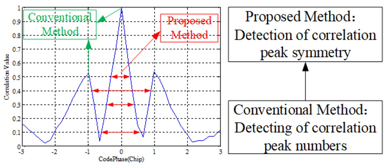
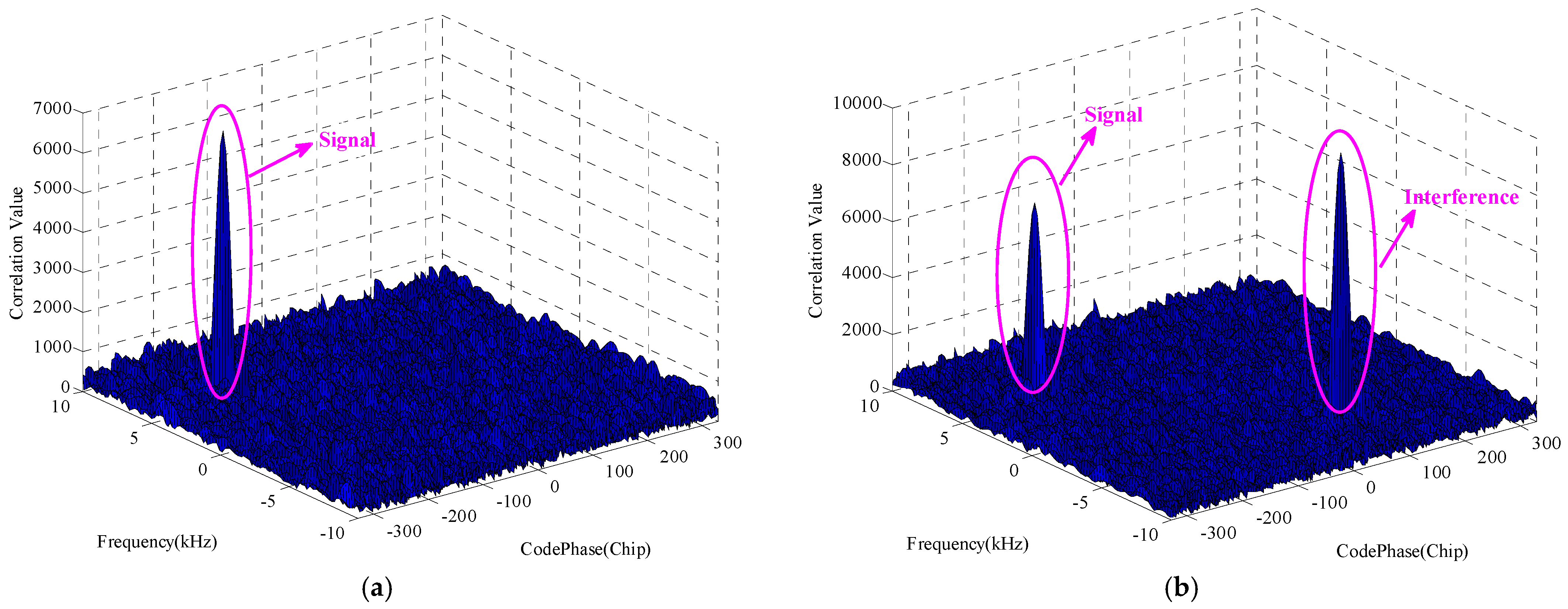
Perform a two-dimensional search on the value of l s i n and compare it with a predetermined threshold. If there are two or more peaks higher than the threshold, it is considered that there is forwarding spoofing interference, and an alarm is issued to the receiver; if there is only one peak higher than the threshold, it is considered to be a real signal, and the tracking link is entered normally.
The correlation peaks with and without spoofing interference are shown in Figure 5, respectively. Whether there is spoofing interference can be easily detected by the number of correlation peaks.

3. Analysis of the Influence of Interference

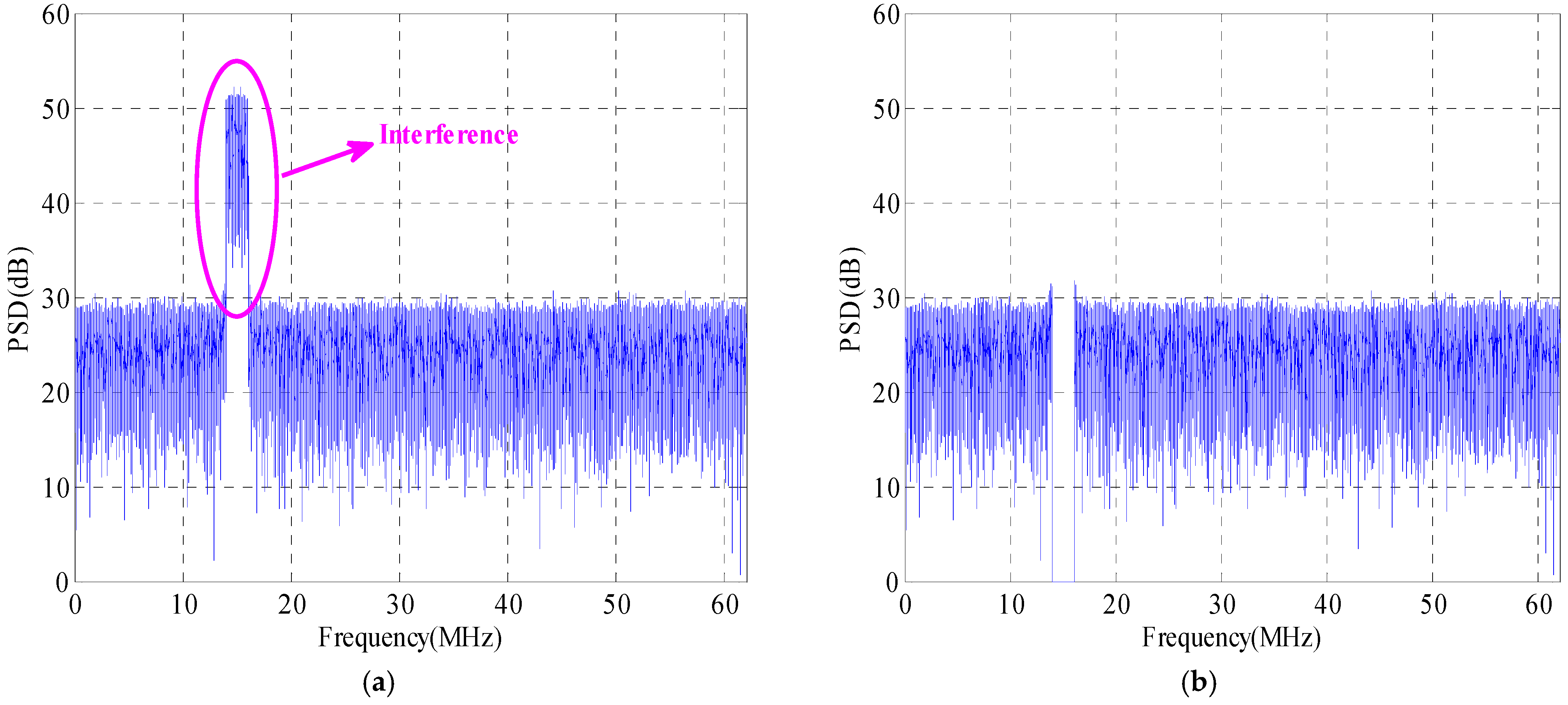
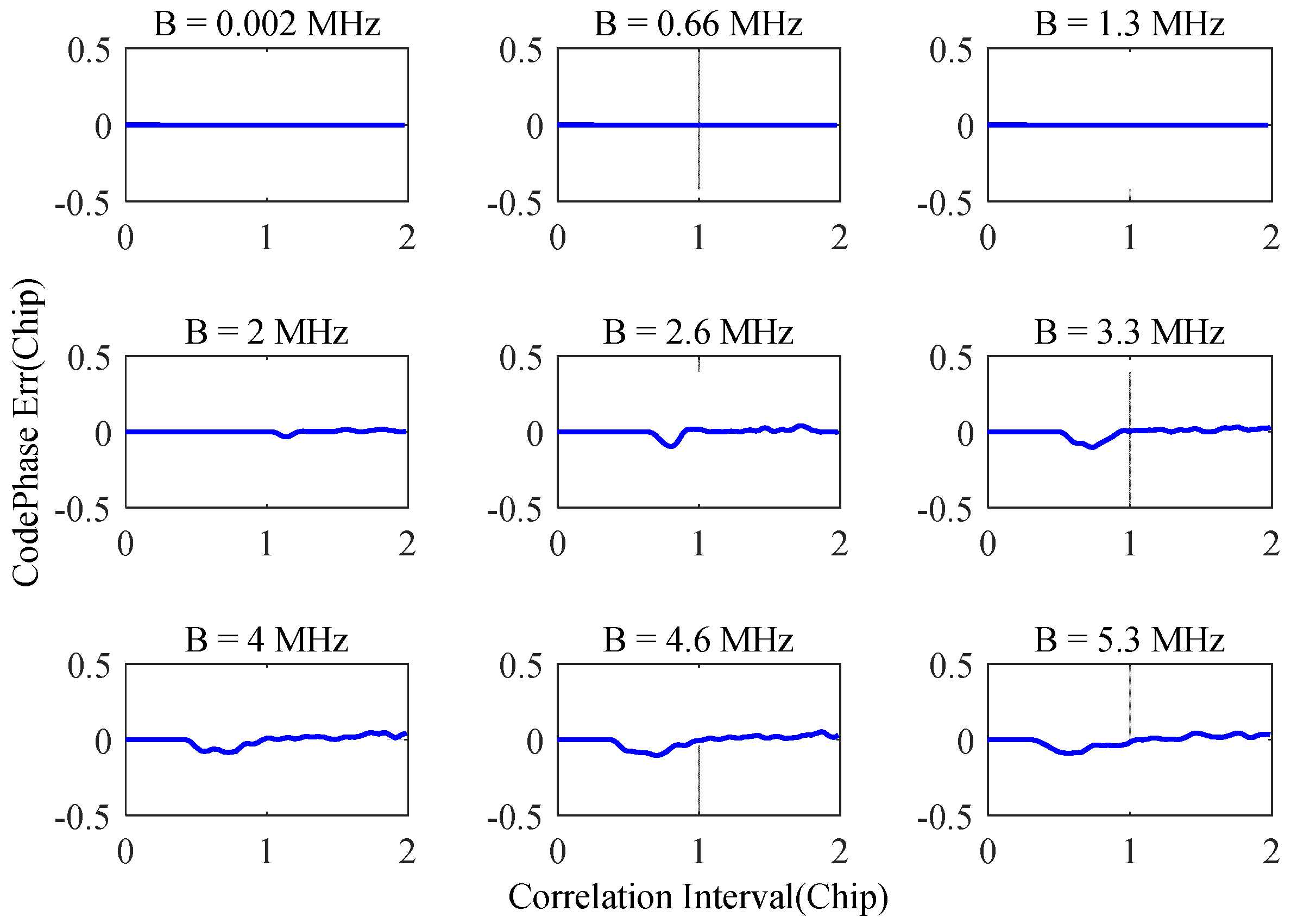
3.1. Analysis of the Influence of Narrowband Interference Suppression

Several studies in the literature have analyzed the influence of frequency-domain anti-jamming on the correlation peak of the navigation signal and reported that its influence is related to the interference frequency, bandwidth, and other factors [39,40]. The frequency of the anti-jamming will cause the rise of the sidelobes of the correlation peak of the navigation signal. From the frequency point of view, when the interference is located at the center frequency of the signal, the sidelobe lift is the most serious. From the perspective of bandwidth, the wider the interference bandwidth, the more serious the sidelobe lift. Under the conditions of anti-jamming, the relationship between the power spectrum of the navigation signal and the correlation function is as follows [41]:
R τ = + H f S f e j 2 π f τ d f
where H f is the frequency domain expression of the anti-interference filter and S f is the power spectral density function of the signal.
From the above formula, it can be concluded that under conditions of different interference bandwidths and interference frequencies, the correlation function will be affected. Taking the Beidou B3I signal system as an example, the main lobe bandwidth of the signal is 20.46 MHz; the influence of anti-interference on the correlation function under different interference bandwidth conditions is shown in Figure 6. With the increase in the interference bandwidth, the distortion of the correlation function of the navigation signal intensifies, accompanied by the rise of the sidelobes. When the interference bandwidth is greater than 4 MHz, the height of the sidelobes reaches half of the main lobe.
In the case of narrowband interference suppression, multiple correlation peaks will appear, and the method of identifying spoofing interference by detecting the number of correlation peaks will fail.

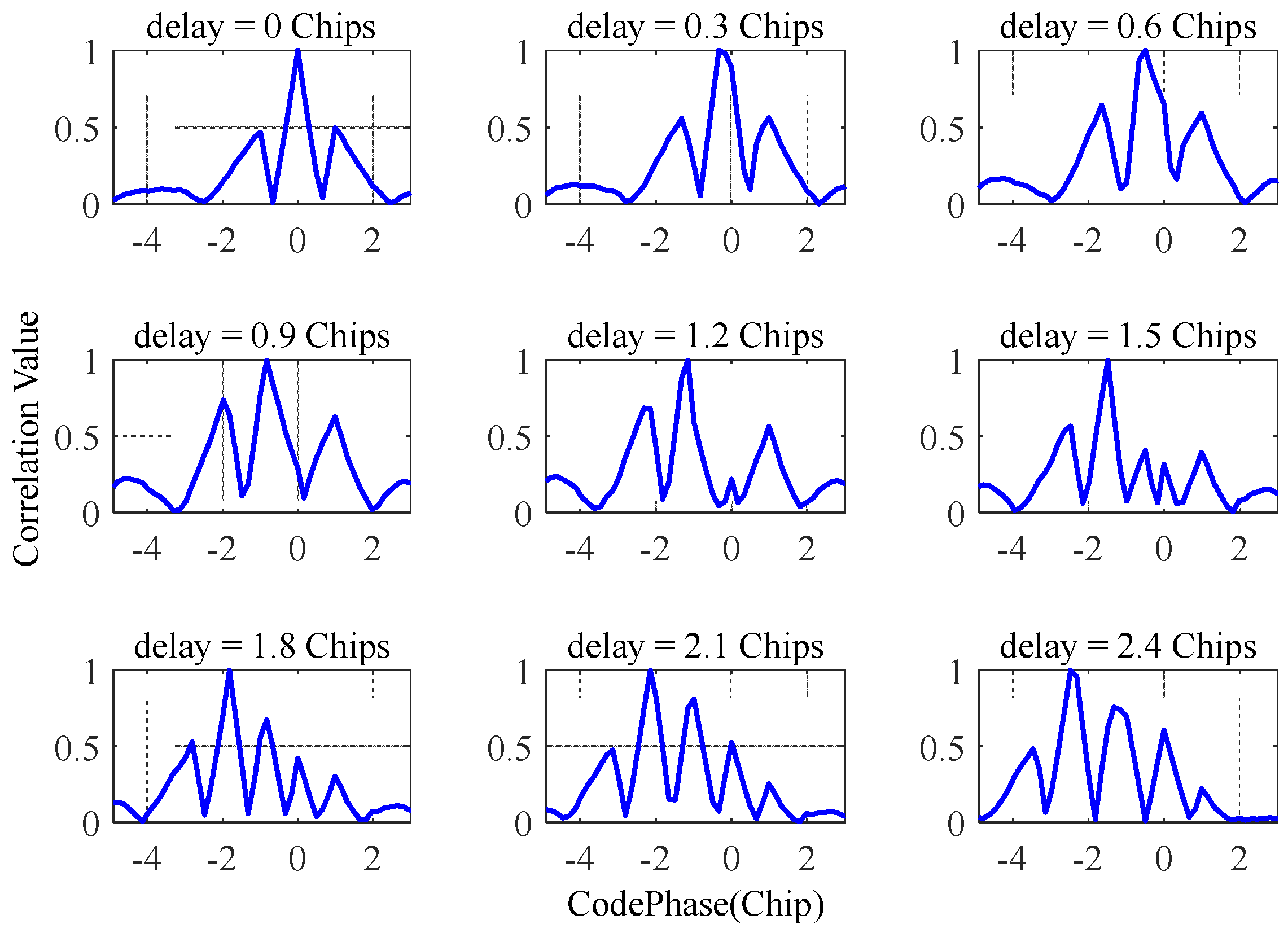
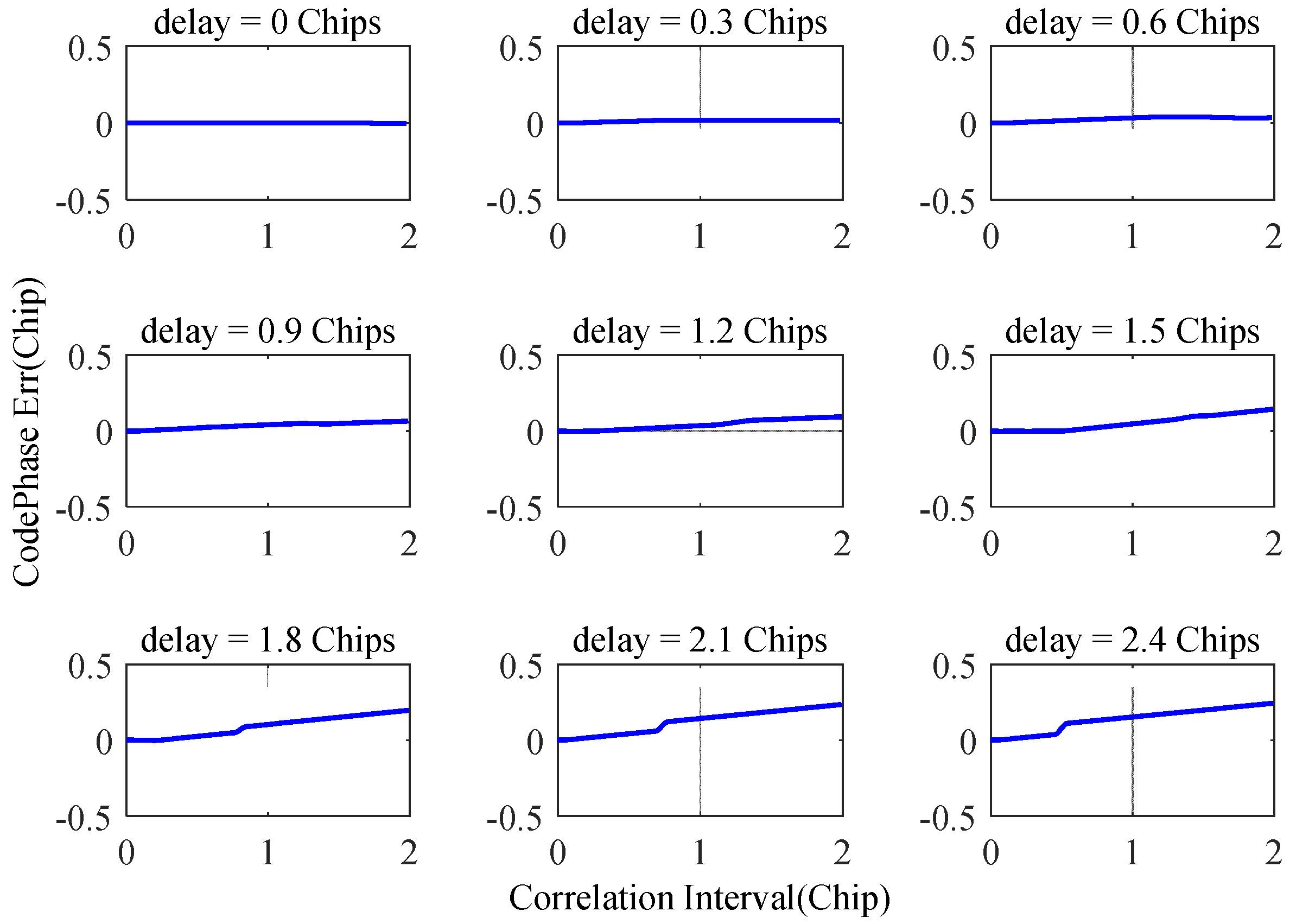
3.2. Analysis of the Influence of Spoofing Interference

Deception-based spoofing interference is a common deception method; in this case, the delayed spoofing interference is gradually separated from the real signal. This method does not require the navigation receiver to re-acquire the signal and can achieve distortion-free switching from the real signal to the deception signal. The mechanism of interference is to adjust the delay difference between the deceptive interference and the real signal. The time delay between the spoofing interference and the real signal has different effects on the correlation function; these effects are shown in Figure 7. The smaller the delay, the harder it is to detect spoofing interference. When the time delay is greater than 1.5 chips, the spoofing interference and the real signal can be clearly distinguished by the correlation peak. Therefore, when the delay between the spoofing interference and the real signal is less than 1.5 chips, it is difficult to detect the spoofing interference by judging the number of correlation peaks.

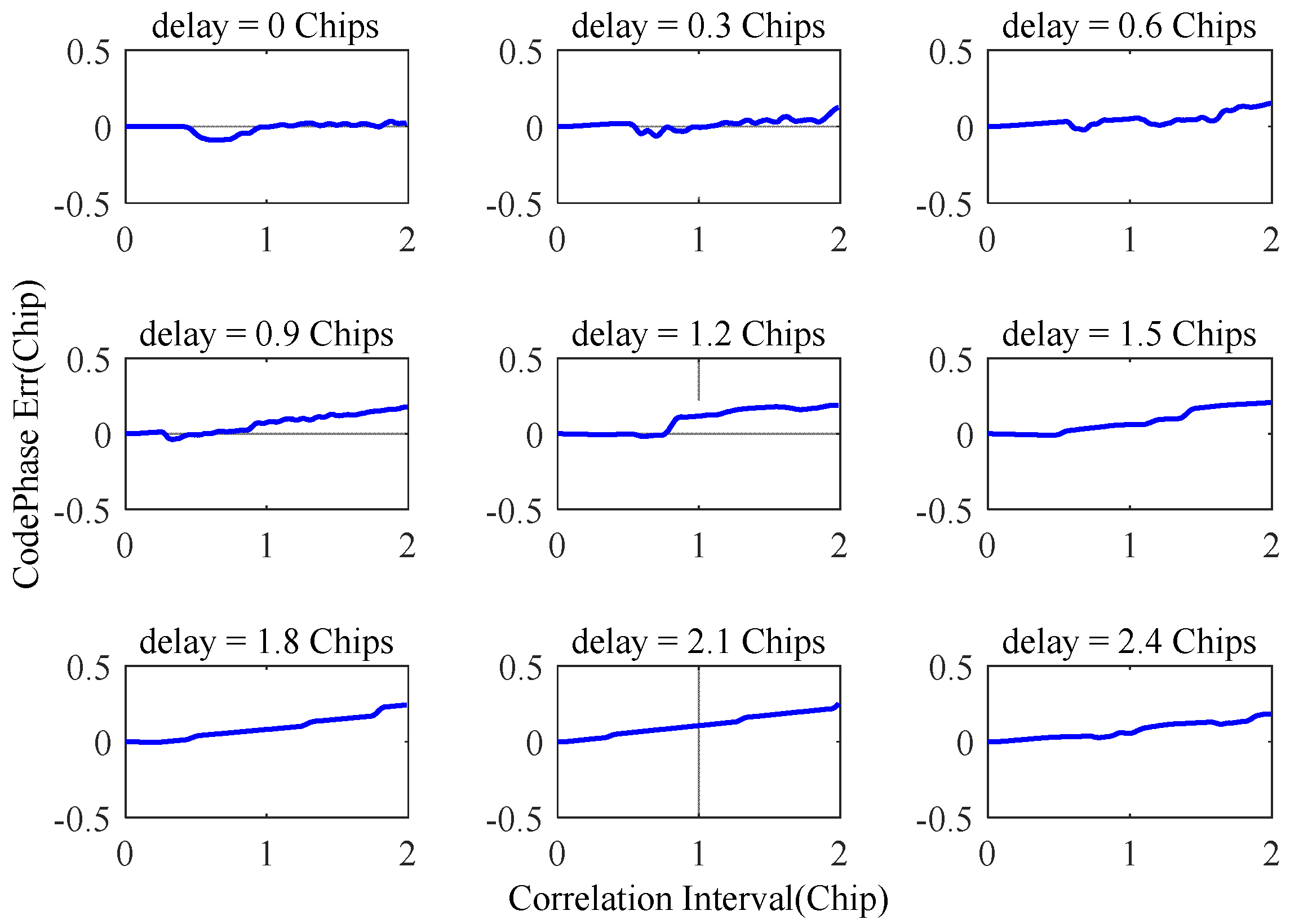
3.3. Analysis of the Influence of Mixed Interference

Narrowband and spoofing interference may coexist. Assuming that the narrowband interference bandwidth is 4 MHz and the center frequency of the interference is located at the center frequency of the navigation signal, when taking the above decoy interference as the research object, in the presence of narrowband interference, the delay difference between the spoof interference and the real signal is related to the correlation function, as shown in Figure 8. Regardless of the delay, multiple correlation peaks will appear. When the time delay is greater than or equal to 1.2 chips, more than 3 correlation peaks will appear. The traditional method of detecting spoofing interference using the number of correlation peaks will identify all correlation peaks as spoofing interference.

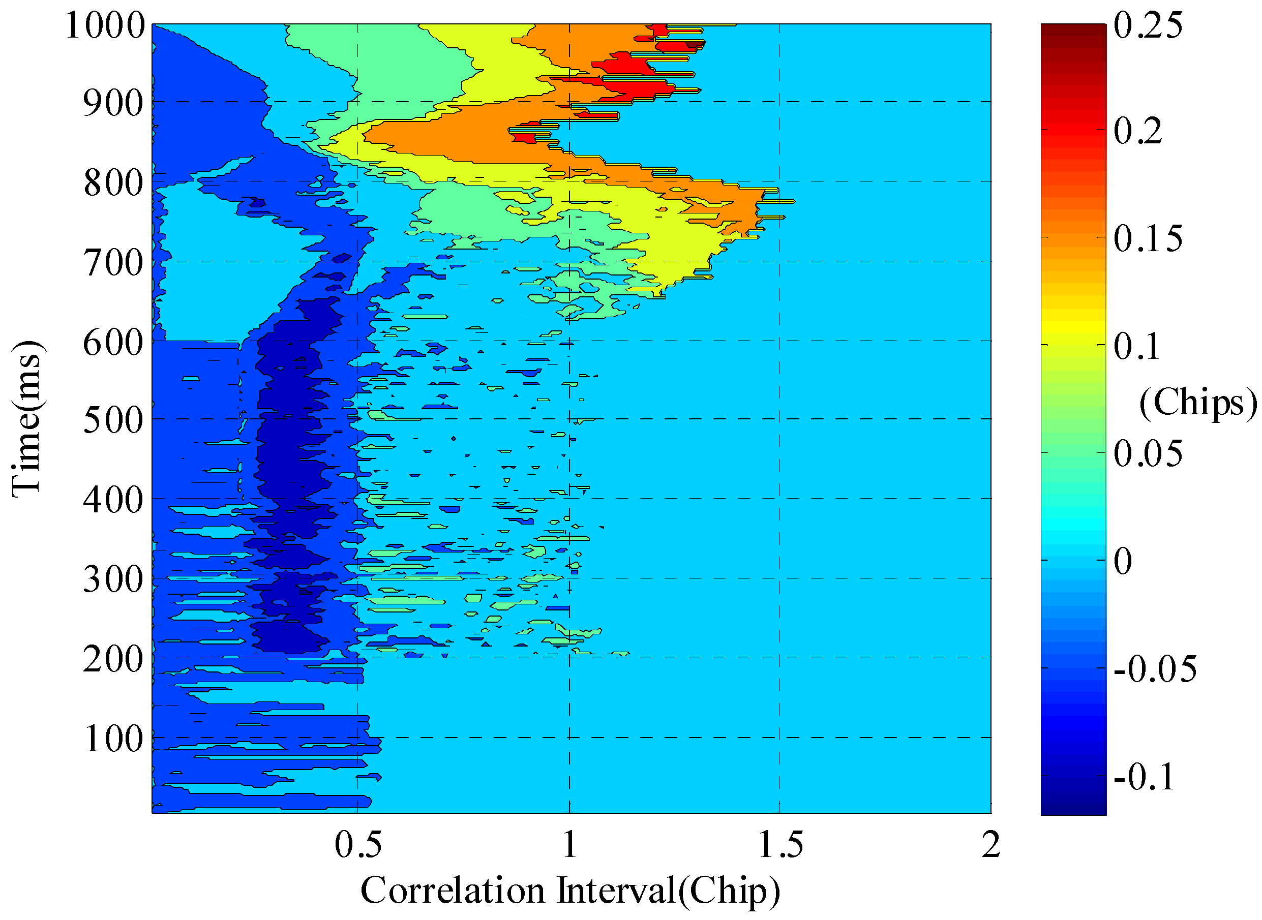
4. Detection Method Based on Correlation Peak Symmetry

A previous study [42] showed that narrowband interference does not destroy the symmetry of the correlation peaks. However, spoofing interference will destroy the symmetry of the correlation peak when the delay difference from the real signal is small. In the satellite navigation signal channel index system, an S-curve deviation is usually used to measure the symmetry of the correlation peak, so that the symmetry can be quantitatively evaluated. In this paper, SCB bias is used as a new method to detect spoofing interference. The definition of SCB is as follows:
τ S C B = τ 0 τ 1 τ 2 2
where τ 0 , τ 1 , and τ 2 satisfy the following constraints:
τ 0 = arg max R τ R τ 1 = R τ 2 τ 1 τ 2 = Δ
In the above formula, R τ is the correlation function between the received signal and the local signal, and is the interval of the correlator.
Using the experimental scenario given in Figure 7, the SCB deviation can be obtained according to the correlation function, as shown in Figure 9. It can be seen from the figure that under the conditions of narrowband interference suppression, the maximum deviation of SCB is less than 0.1 chip, while the fluctuation of SCB deviation has a certain randomness, and it is difficult to describe its changing trend.
Using the experimental scenario shown in Figure 7, the SCB deviation can be obtained according to the correlation function, as shown in Figure 10. It can be seen from Figure 10 that under the conditions of spoofing interference, the maximum deviation of SCB reaches about 0.3 chips, the symmetry of the correlation peak is destroyed, and the deviation of SCB appears to increase with the increase in the correlation interval.
Taking the experimental scenario shown in Figure 8, the SCB deviation can be obtained according to the correlation function, as shown in Figure 11. It can be seen from the figure that under conditions of mixed interference, the maximum deviation of SCB also reaches about 0.3 chips, and the symmetry of the correlation peak is destroyed, in a similar way to the scenario in Figure 10. It is further verified that the narrowband interference suppression will not destroy the symmetry of the correlation peak, but the spoofing interference will destroy the symmetry.

5. Experimental Verification of the Software Receiver

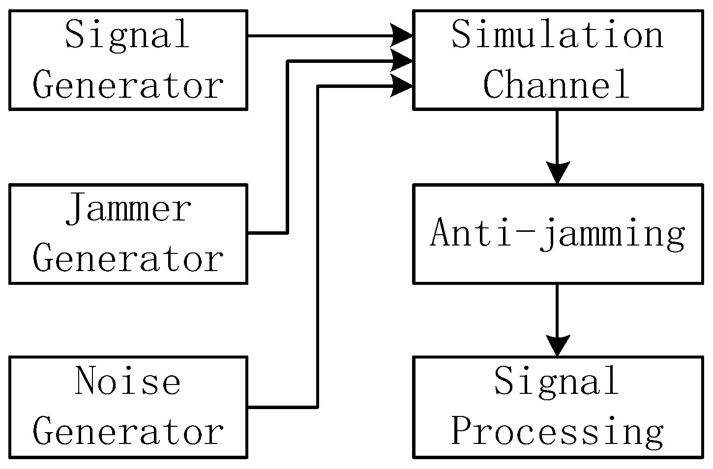
5.1. Experimental Platform

The simulation verification platform simulates a real navigation receiver signal-processing terminal; its block diagram is shown in Figure 12. The software receiver was designed by our group and was processed using MATLAB software. The signal adopts the pseudo-random noise code 1 (PRN1) of the Beidou-3 B3I signal. In the anti-jamming simulation, the interference is Gaussian noise of 2.046 MHz, while the simulation channel combines the signal, the interference, and the noise. The narrowband interference power is 50 dB higher than the noise, while the real signal power is 20 dB weaker than the noise. The anti-jamming method uses frequency-domain anti-jamming to detect deception interference in signal processing.

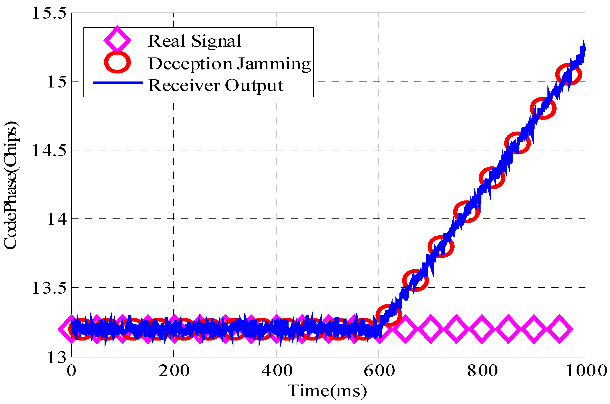
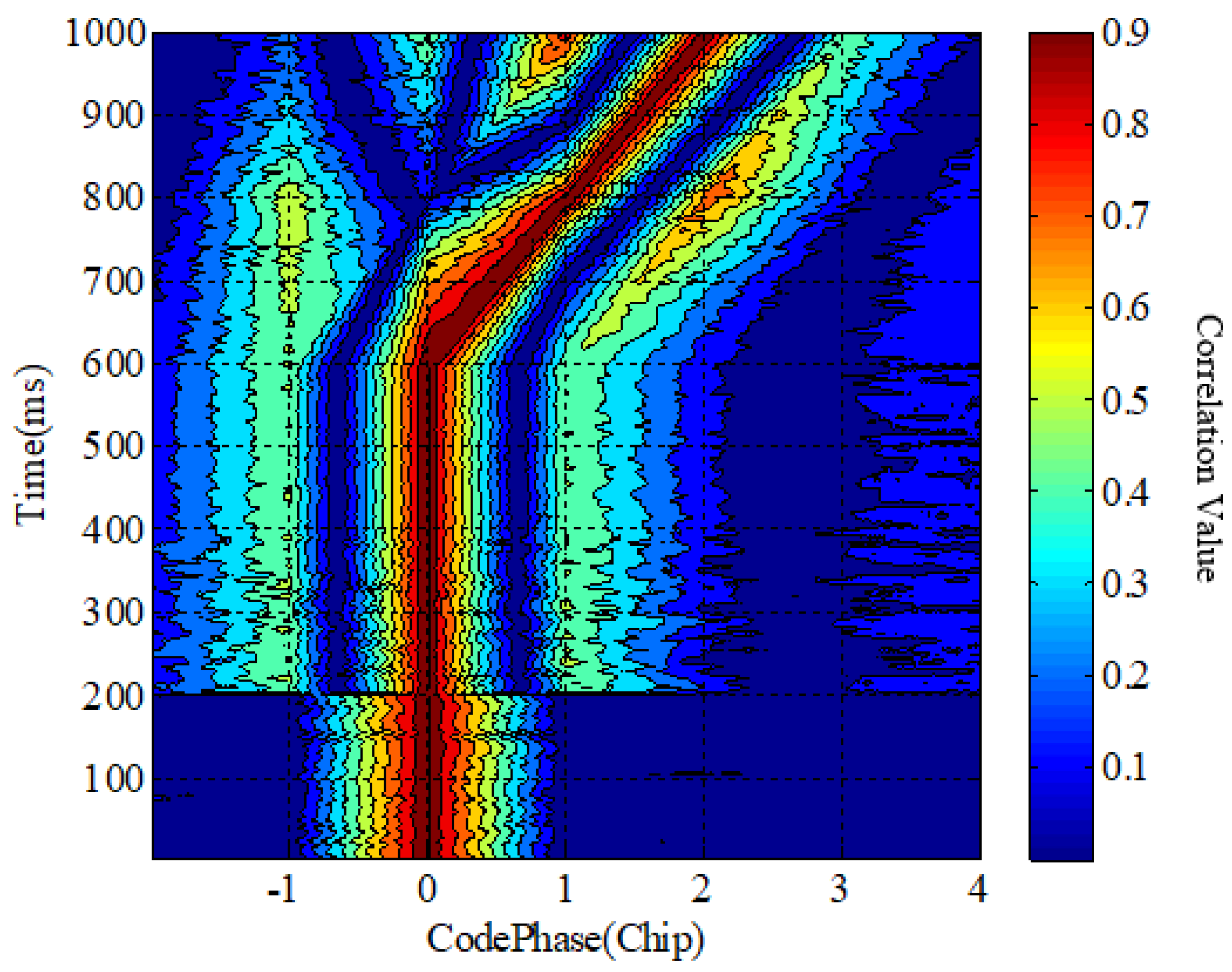
5.2. Simulation Experiment

In this simulation, the duration is set to 1 s. In order to verify the effectiveness of the method proposed in this paper, the method of dynamic interference is adopted. When the software receiver starts to work, there is no narrowband interference or spoof interference. When the software receiver runs to 200 ms, the narrowband interference is added. At 400 ms, the spoof interference is added. The deception interference power is 3 dB higher than the real signal, and the signal structure is the same as the real signal. The deception interference at 400 ms is false. The distance is the same as the real signal. At 600 ms, the spoofing interference is dynamically added, and the deflection is started at a speed of 0.005 chips/ms until the software receiver runs out.
The software receiver tracks the signal and outputs pseudo-range measurements. Figure 13 shows the comparison of the pseudo-range measurement value output by the software receiver, the pseudo-range value of the real signal, and the pseudo-range value of the spoofing interference. When the software receiver runs to 600 ms, the tracking is deceived by the interference, the receiver is deceived by the deception interference, and starts to output the wrong pseudo-range value.
The correlation function waterfall chart represents the change in the correlation function over time. It is essentially a three-dimensional graph. The x-axis represents the code phase, the y-axis represents the time, the z-axis represents the correlation value, and the z-axis is represented by different colors. It is difficult to accurately detect spoofing interference using the waterfall plot of the correlation function. A waterfall diagram of the correlated peaks is shown in Figure 14.
In Figure 14, if the traditional spoofing jamming detection method is adopted, the sidelobe of the correlation peak is raised due to the narrowband jamming suppression and the spoof jamming will be detected at 200 ms, which is an example of incorrect spoof jamming detection.
The SCB deviation curve is drawn according to the correlation function, and the SCB waterfall chart is shown in Figure 15. Spoofing interference can easily be detected from the SCB waterfall chart.
Using the traditional detection method of the number of correlation peaks and the SCB curve threshold method, the thresholds are set to 0.12/0.14/0.16/0.18, respectively, to detect the spoofing interference; the detection results are shown in Figure 16.

6. Discussion

In the traditional method, the number of correlation peaks can determine whether there is spoofing interference. In the absence of spoofing interference, there is only one correlation peak, while with spoofing interference, there will be multiple correlation peaks. In addition, in the case of narrowband interference, the interference suppression method in the time domain or frequency domain will distort the shape of the correlation peak, resulting in an elevation of the sidelobe of the correlation peak. Therefore, when narrowband interference occurs, it is assumed that there is deception interference with the traditional method; that is, a false alarm of detection is triggered.
Although the suppression of narrowband interference will cause the distortion of the correlation peak, it will not destroy the symmetry of the correlation peak, and the existence of spoofing interference will not only change the number of correlation peaks but also cause the symmetry of the correlation peak to change. In the case of the coexistence of narrowband and spoofing interference, the traditional method that only relies on the number of correlation peaks will trigger serious false alarms. However, this paper proposes a method based on correlation peak symmetry detection, which can effectively improve the detection performance of spoofing interference. Under the typical scenario conditions of the simulation experiments, using the SCB curve threshold method, when the threshold is set to 0.12, the spoofing interference is detected at a time of 651 ms, and the difference between the spoofing interference and the real signal is about 7.5 m at this time.

7. Conclusions

In this paper, we analyze methods for detecting spoofing interference based on the number of correlation peaks in the scenarios of narrowband interference, spoofing interference, and their hybrid interference. A spoofing interference detection method, based on the symmetry of the correlation peak is proposed, and a simulation verification is carried out on the software receiver platform.
The outcomes of the study are the following:
(1)
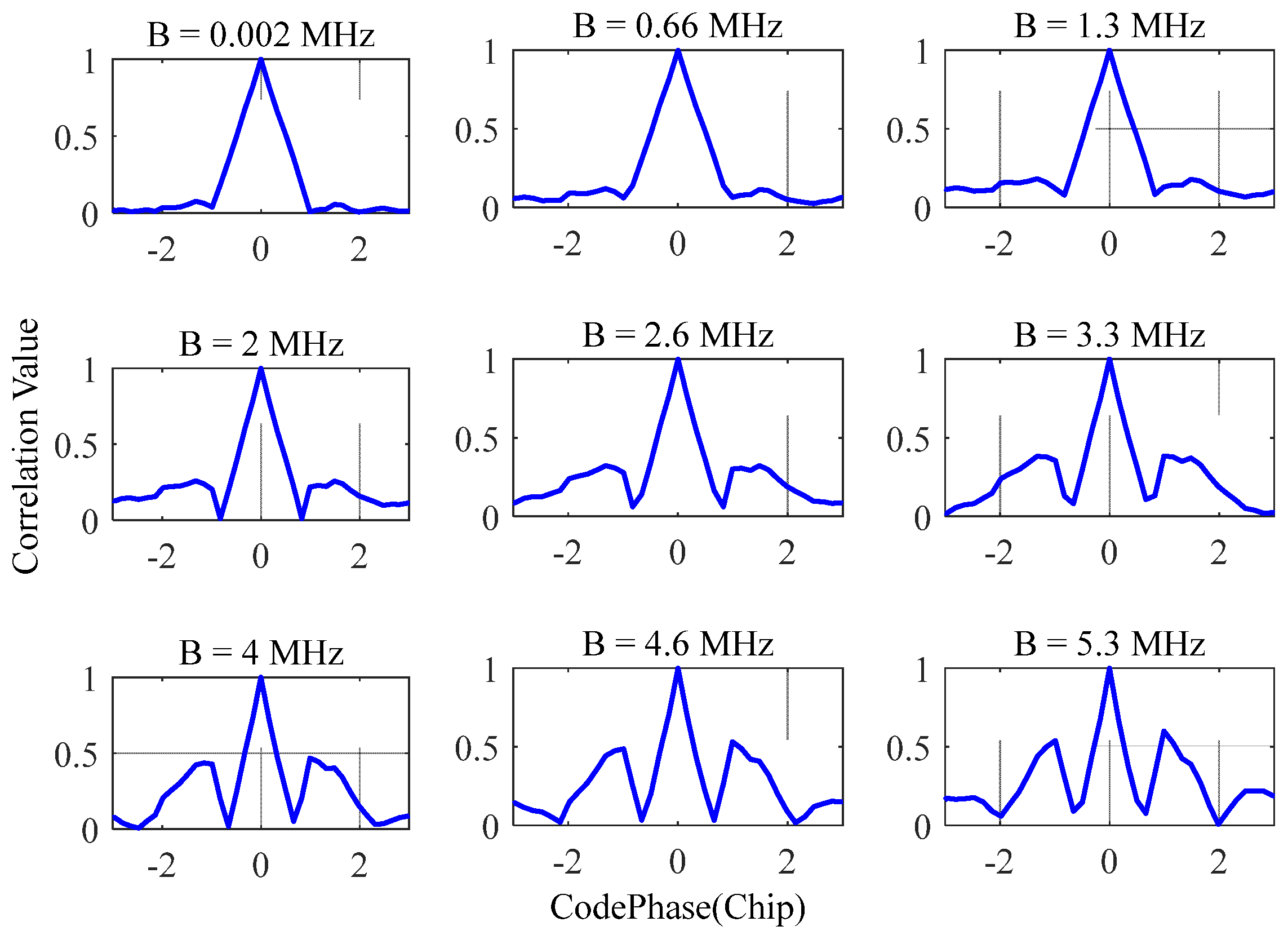
The suppression of narrow-band interference will cause the rise of the sidelobes of the correlation peak. If the detection method of spoofing interference based on the number of correlation peaks is adopted, this will cause false alarms in the detection of spoofing interference.
(2)
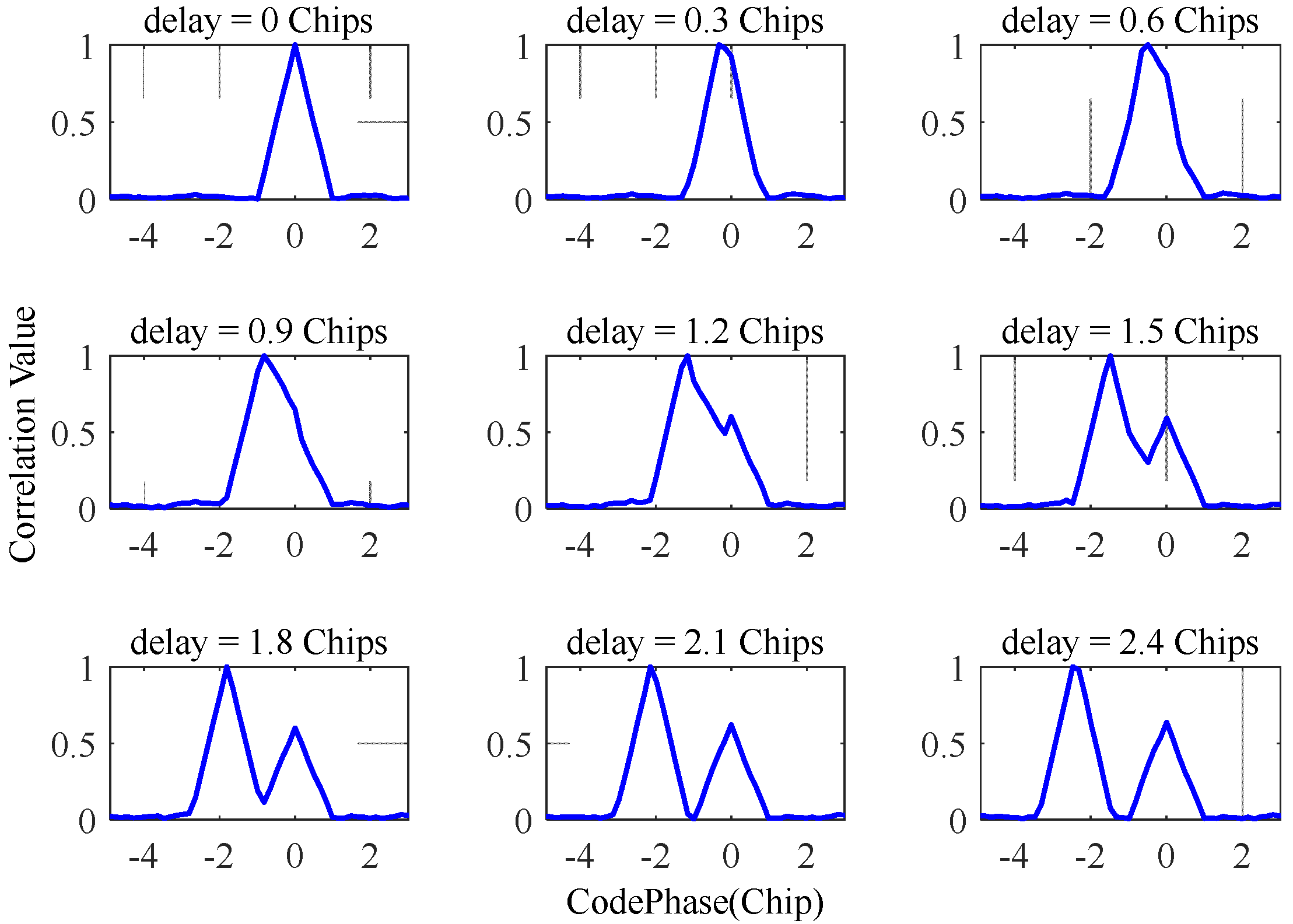
When the delay between spoofing interference and the real signal is less than 1 chip, the displayed correlation function is still a correlation peak, and the spoofing interference detection method based on the number of correlation peaks will be invalid.
(3)
When narrowband interference and spoofing interference coexist, the number of correlation peaks will be complicated, and the detection of spoofing interference cannot be achieved solely by the number of correlation peaks.
(4)
Narrowband interference will not destroy the symmetry of the correlation peak, whereas spoofing interference will destroy the symmetry of the correlation peak. Using the symmetry of detecting deception interference can effectively realize the detection of deception interference.
In the scenario mentioned in the simulation experiment, when narrowband jamming and spoofing jamming coexist and the delay difference between the real signal and the spoofing signal is 7.5 m, the method proposed in this paper can effectively identify the spoofing signal, which solves the problem of spoofing interference identification under mixed jamming conditions.
Spoofing interference detection and spoofing interference is a game between the attacker and the defender, and new forms of spoofing will need new methods of detection. The spoofing interference detection method in this paper provides a new solution for the detection of spoofing interference.

Author Contributions

L.H. and Z.L. (Zhe Liu) performed the theoretical study, conducted the experiments, processed the data, and wrote the manuscript; Z.L. (Zukun Lu) designed the system, provided research suggestions, and revised the manuscript, together with C.R., Z.X. and J.S. helped in performing the experiments; B.L. provided the experiment equipment and suggestions for the manuscript. All authors have read and agreed to the published version of the manuscript.

Funding

This research was supported in part by the Natural Science Foundation of China (NSFC) grants 62003354.

Acknowledgments

The authors would like to thank the editors and reviewers for their efforts to help the publication of this paper.

Conflicts of Interest

The authors declare no conflict of interest.

References

  1. Xue, B.; Wang, H.; Yuan, Y. Performance of BeiDou-3 signal-in-space ranging errors: Accuracy and distribution. GPS Solut. 2021, 25, 23. [Google Scholar] [CrossRef]
  2. Alexandre, M.; Alvaro, S.; Jean-Paul, B.; Félix, P.; Sylvain, L. Analysis of GNSS Displacements in Europe and Their Comparison with Hydrological Loading Models. Remote Sens. 2021, 13, 4523. [Google Scholar]
  3. Lu, Z.; Chen, F.; Xie, Y.; Sun, Y.; Cai, H. High Precision Pseudo-Range Measurement in GNSS Anti-jamming Antenna Array Processing. Electronics 2020, 9, 412. [Google Scholar] [CrossRef] [Green Version]
  4. Zhang, Z.; Li, B.; Nie, L. Initial assessment of BeiDou-3 global navigation satellite system: Signal quality, RTK and PPP. GPS Solut. 2019, 23, 111. [Google Scholar] [CrossRef]
  5. Liu, Y.; Cao, Y.; Tang, C.; Chen, J.; Zhao, L.; Zhou, S.; Hu, X.; Tian, Q.; Yang, Y. Pseudorange Bias Analysis and Preliminary Service Performance Evaluation of BDSBAS. Remote Sens. 2021, 13, 4815. [Google Scholar] [CrossRef]
  6. Sara, J.H.; Nagaraj, C.S.; Dennis, M.A. Fitlering and quantization effects on GNSS successive interference cancellation. IEEE Trans. Aerosp. Electron. Syst. 2020, 56, 924–936. [Google Scholar]
  7. Zhang, P.; Tu, R.; Zhang, R.; Gao, Y.; Cai, H. Combining GPS, BeiDou, and Galileo Satellite Systems for Time and Frequency Transfer Based on Carrier Phase Observations. Remote Sens. 2018, 10, 324. [Google Scholar] [CrossRef] [Green Version]
  8. Ladina, S.; Michael, M.; Christoph, M. Impact of GPS processing on the estimation of snow water equivalent using refracted GPS signals. IEEE Trans. Geosci. Remote Sens. 2020, 58, 123–135. [Google Scholar]
  9. Song, J.; Lu, Z.; Xiao, Z.; Li, B.; Sun, G. Optimal Order of Time-Domain Adaptive Filter for Anti-jamming Navigation Receiver. Remote Sens. 2022, 14, 48. [Google Scholar] [CrossRef]
  10. Huang, L.; Lu, Z.; Ren, C.; Xiao, Z.; Song, J.; Li, B. Suppression of Jammer Multipath in GNSS Antenna Array Receiver. Remote Sens. 2022, 14, 350. [Google Scholar] [CrossRef]
  11. Bertold, V.D.B.; Sofie, P. Keeping UAVs under control during GPS jamming. IEEE Syst. J. 2019, 13, 2010–2021. [Google Scholar]
  12. Lu, Z.; Chen, H.; Chen, F.; Nie, J.; Ou, G. Blind Adaptive Channel Mismatch Equalization Method for GNSS Antenna Arrays. IET Radar Sonar Navig. 2018, 12, 383–389. [Google Scholar] [CrossRef]
  13. Humphreys, T.E. Detection Strategy for Cryptographic GNSS Anti-Spoofing. IEEE Trans. Aerosp. Electron. Syst. 2013, 49, 1073. [Google Scholar] [CrossRef]
  14. Adnan, K.; Jian, D.; Rong, S. A metamaterial-based compact planar monopole antenna for Wi-Fi and UWB applications. Sensors 2019, 19, 5426. [Google Scholar] [CrossRef] [Green Version]
  15. Wu, Z.; Zhang, Y.; Yang, Y.; Liang, C.; Liu, R. Spoofing and Anti-Spoofing Technologies of Global Navigation Satellite System: A Survey. IEEE Access 2020, 8, 165444. [Google Scholar] [CrossRef]
  16. Fan, Y.; Zhang, Z.; Trinkle, M.; Dimitrovski, A.D.; Song, J.B.; Li, H. A Cross-Layer Defense Mechanism Against GPS Spoofing Attacks on PMUs in Smart Grids. IEEE Trans. Smart Grid 2014, 6, 2659–2668. [Google Scholar] [CrossRef]
  17. Siamak, S.; Dehghani, M.; Mohammadi, M. Dynamic GPS Spoofing Attack Detection, Localization, and Measurement Correction Exploiting PMU and SCADA. IEEE Syst. J. 2020, 15, 2531–2540. [Google Scholar] [CrossRef]
  18. Silva, S.D.; Kim, J.; Cotilla-Sanchez, E.; Hagan, T. On PMU Data Integrity Under GPS Spoofing Attacks: A Sparse Error Correction Framework. IEEE Trans. Power Syst. 2021, 36, 5317–5332. [Google Scholar] [CrossRef]
  19. Harvey, W.; Rainwater, C.; Cothren, J. Direct Aerial Visual Geolocalization Using Deep Neural Networks. Remote Sens. 2021, 13, 4017. [Google Scholar] [CrossRef]
  20. Schmidt, E.; Gatsis, N.; Akopian, D. A GPS Spoofing Detection and Classification Correlator-Based Technique Using the LASSO. IEEE Trans. Aerosp. Electron. Syst. 2020, 56, 4224–4237. [Google Scholar] [CrossRef]
  21. Wei, X.; Aman, M.N.; Sikdar, B. Exploiting Correlation Among GPS Signals to Detect GPS Spoofing in Power Grids. IEEE Trans. Ind. Appl. 2021, 58, 697–708. [Google Scholar] [CrossRef]
  22. Lu, Z.; Nie, J.; Chen, F.; Ou, G. Impact on Anti-jamming Performance of Channel Mismatch in GNSS Antenna Arrays Receivers. Int. J. Antennas Propag. 2016, 2016, 1909708. [Google Scholar] [CrossRef]
  23. Mohamed, T.; Michael, J.; Haidy, E.; Aboelmagd, N. GPS Swept Anti-Jamming Technique Based on Fast Orthogonal Search (FOS). Remote Sens. 2021, 21, 3706. [Google Scholar] [CrossRef]
  24. Jian, D.; Chang, D.; Jin, M. A Low-Profile Wideband Linear-to-Circular Polarization Conversion Slot Antenna Using metasurface. Materials 2020, 13, 1164. [Google Scholar] [CrossRef] [Green Version]
  25. Lu, Z.; Nie, J.; Wan, Y.; Ou, G. Optimal reference element for interference suppression in GNSS antenna arrays under channel mismatch. IET Radar Sonar Navig. 2017, 11, 1161–1169. [Google Scholar] [CrossRef]
  26. Wang, H.M.; Huang, K.W.; Tsiftsis, T.A. Multiple Antennas Secure Transmission Under Pilot Spoofing and Jamming Attack. IEEE J. Sel. Areas Commun. 2018, 36, 860–876. [Google Scholar] [CrossRef] [Green Version]
  27. Lu, Z.; Nie, J.; Chen, F.; Chen, H.; Ou, G. Adaptive Time Taps of STAP Under Channel Mismatch for GNSS Antenna Arrays. IEEE Trans. Instrum. Meas. 2017, 66, 2813–2824. [Google Scholar] [CrossRef]
  28. Xiao, L.; Li, X.; Wang, G. GNSS Spoofing Detection Using Pseudo-range Double Differences between Two Receivers. In Proceedings of the IEEE 7th International Conference on Computer Science and Network Technology (ICCSNT), Dalian, China, 19–20 October 2019; pp. 498–502. [Google Scholar] [CrossRef]
  29. Xiao, L.; Li, X.; Liao, Z. GNSS Spoofing DetectionWith Using Planar Array. In Proceedings of the 7th International Conference on Information Science and Control Engineering (ICISCE), Changsha, China, 18–20 December 2020; pp. 664–668. [Google Scholar] [CrossRef]
  30. Liu, Y.; Hu, H. The Research on GPS Frequency Domain Anti-Jamming Algorithms. In Proceedings of the 5th International Conference on Wireless Communications, Networking and Mobile Computing, Beijing, China, 24–26 September 2009; pp. 1–3. [Google Scholar] [CrossRef]
  31. Fan, G.T.; Huang, Y.B.; Su, Y.X.; Li, J.Y.; Sun, G.F. A reduced bias delay lock loop for adaptive filters. Adv. Space Res. 2017, 59, 230. [Google Scholar] [CrossRef]
  32. Zhou, Z.; Wei, Y. The Influence of Automatic Gain Control on Narrowband Frequency Domain GPS Anti-Jamming Receiver. In Proceedings of the 2021 IEEE 21st International Conference on Communication Technology (ICCT), Tianjin, China, 13–16 October 2021; pp. 497–501. [Google Scholar] [CrossRef]
  33. Wang, L.; Zhao, H.; Xiong, G.; Zhang, S. AM-FM interference suppression for GPS receivers based on time-frequency analysis and synthesis. In Proceedings of the 2005 IEEE International Symposium on Microwave, Antenna, Propagation and EMC Technologies for Wireless Communications, Beijing, China, 8–12 August 2005; pp. 1378–1381. [Google Scholar] [CrossRef]
  34. Lv, W.; Shen, C.; Gui, F.; Tian, Z.; Jiang, D. Real-Time Spectrum Analyzer Based on All Phase FFT Spectrum Analysis. In Proceedings of the 2013 Fourth International Conference on Digital Manufacturing & Automation, Shinan, China, 29–30 June 2013; pp. 966–969. [Google Scholar]
  35. Rao, K.D.; Swamy, M.N.S. New approach for suppression of FM jamming in GPS receivers. IEEE Trans. Aerosp. Electron. Syst. 2006, 42, 1464–1474. [Google Scholar] [CrossRef]
  36. Bethi, P.; Pathipati, S. Stealthy GPS Spoofing: Spoofer Systems, Spoofing Techniques and Strategies. In Proceedings of the 2020 IEEE 17th India Council International Conference (INDICON), New Delhi, India, 10–13 December 2020; pp. 1–7. [Google Scholar] [CrossRef]
  37. Kim, T.H.; Sin, C.S.; Lee, S.; Kim, J.H. Analysis of effect of anti-spoofing signal for mitigating to spoofing in GPS L1 signal. In Proceedings of the 2013 13th International Conference on Control, Automation and Systems (ICCAS 2013), Gwangju, Korea, 20–23 October 2013; pp. 523–526. [Google Scholar] [CrossRef]
  38. Pardhasaradhi, B.; Srihari, P.; Aparna, P. Spoofer-to-Target Association in Multi-Spoofer Multi-Target Scenario for Stealthy GPS Spoofing. IEEE Access 2021, 9, 108675–108688. [Google Scholar] [CrossRef]
  39. Lu, Z.; Song, J.; Huang, L.; Ren, C.; Xiao, Z.; Li, B. Distortionless 1/2 Overlap Windowing in Frequency Domain Anti-Jamming of Satellite Navigation Receivers. Remote Sens. 2022, 14, 1801. [Google Scholar] [CrossRef]
  40. Huo, S.; Nie, J.; Tang, X.; Wang, F. Minimum Energy Block Technique Against Pulsed and Narrowband Mixed Interferers for Single Antenna GNSS Receivers. IEEE Commun. Lett. 2015, 19, 1933–1936. [Google Scholar] [CrossRef]
  41. Xu, W.; Xing, W.; Fang, C.; Huang, P.; Tan, W.; Gao, Z. RFI Suppression for SAR Systems Based on Removed Spectrum Iterative Adaptive Approach. Remote Sens. 2020, 12, 3520. [Google Scholar] [CrossRef]
  42. Liu, Z.; Pang, J.; Liu, Y.; Wang, F. Double Strobe Technique for Unambiguous Tracking of TMBOC Modulated Signal in GPS. IEEE Signal Process. Lett. 2015, 22, 2204–2208. [Google Scholar] [CrossRef]
Figure 1. Satellite navigation receiver architecture.
Remotesensing 14 02506 g001
Figure 2. The basic principle of frequency domain anti-jamming.
Remotesensing 14 02506 g002
Figure 3. Spectrum before and after anti-jamming: (a) before anti-jamming, (b) after anti-jamming.
Remotesensing 14 02506 g003
Figure 4. Generation principle of forwarding spoofing interference.
Remotesensing 14 02506 g004
Figure 5. Detection results of spoofing interference: (a) without spoofing interference, (b) with spoofing interference.
Remotesensing 14 02506 g005
Figure 6. Correlation peak distortion caused by narrowband interference suppression.
Remotesensing 14 02506 g006
Figure 7. The effect of spoofing interference on correlation peaks.
Remotesensing 14 02506 g007
Figure 8. The effect of mixed interference on the correlation peaks.
Remotesensing 14 02506 g008
Figure 9. SCB distortions caused by narrowband interference suppression.
Remotesensing 14 02506 g009
Figure 10. Impact of pull-off spoofing interference on SCB.
Remotesensing 14 02506 g010
Figure 11. The impact of mixed interference on SCB.
Remotesensing 14 02506 g011
Figure 12. Software receiver simulation block diagram.
Remotesensing 14 02506 g012
Figure 13. Pseudo-range measurements in interference scenarios.
Remotesensing 14 02506 g013
Figure 14. Waterfall diagram of the correlation function in an interference scenario.
Remotesensing 14 02506 g014
Figure 15. SCB waterfall diagram in the interference scenario.
Remotesensing 14 02506 g015
Figure 16. Deception interference detection results in interference scenarios.
Remotesensing 14 02506 g016
Publisher’s Note: MDPI stays neutral with regard to jurisdictional claims in published maps and institutional affiliations.

