
Exploiting the Sensitivity of Dual-Frequency Smartphones and GNSS Geodetic Receivers for Jammer Localization


1
Faculty of Civil and Geodetic Engineering, University of Ljubljana, Jamova Cesta 2, SI-1000 Ljubljana, Slovenia
2
Faculty of Maritime Studies and Transport, University of Ljubljana, Pot pomorščakov 4, SI-6320 Portorož, Slovenia
*
Author to whom correspondence should be addressed.
Remote Sens. 2023, 15(4), 1157; https://0-doi-org.brum.beds.ac.uk/10.3390/rs15041157
Submission received: 31 December 2022
/
Revised: 6 February 2023
/
Accepted: 17 February 2023
/
Published: 20 February 2023
(This article belongs to the Special Issue Smartphone-Derived GNSS Measurements Characterization for Precise Positioning and Navigation Applications)
Abstract
:Smartphones now dominate the Global Navigation Satellite System (GNSS) devices capable of collecting raw data. However, they also offer valuable research opportunities in intentional jamming, which has become a serious threat to the GNSS. Smartphones have the potential to locate jammers, but their robustness and sensitivity range need to be investigated first. In this study, the response of smartphones with dual-frequency, multi-constellation reception capability, namely, a Xiaomi Mi8, a Xiaomi 11T, a Samsung Galaxy S20, and a Huawei P40, to various single- and multi-frequency jammers is investigated. The two-day jamming experiments were conducted in a remote area with minimal impact on users, using these smartphones and two Leica GS18 and two Leica GS15 geodetic receivers, which were placed statically at the side of a road and in a line, approximately 10 m apart. A vehicle with jammers installed passed them several times at a constant speed. In one scenario, a person carrying the jammer was constantly tracked using a tacheometer to determine the exact distance to the receivers for each time stamp. The aim was, first, to determine the effects of the various jammers on the smartphones’ positioning capabilities and to compare their response in terms of the speed and quality of repositioning with professional geodetic receivers. Second, a method was developed to determine the position of the interference source by varying the signal loss threshold and the recovery time on the smartphone and the decaying carrier-to-noise ratio (CNR). The results indicate that GNSS observations from smartphones have an advantage over geodetic receivers in terms of localizing jammers because they do not lose the signal near the source of the jamming, but they are characterized by sudden drops in the CNR.
1. Introduction
Today, the Global Navigation Satellite System (GNSS) is an invaluable asset, but its smooth operation is also vulnerable, a point that should not be underestimated. As the GNSS provides accurate positioning, navigation, and timing (PNT) for civil and military users and many infrastructures, including logistics, telecommunications, energy, finance, and other supply-chain sectors, the issues of reliability, robustness, and integrity are a growing concern. The problem with the GNSS’s vulnerability is that most civilian signals are weak and not protected against interference. Therefore, ordinary users or GNSS-based infrastructures can easily become the target of unintentional or even malicious jamming and/or spoofing. At present, the best way to combat such malicious interference is still to locate the source and disable it.
Currently, smartphones, tablets, and wristwatches are the dominant GNSS devices and therefore could be used to detect or even locate sources of interference. An important milestone in recognizing their potential beyond straightforward positioning was the Google I/O 2016 conference, where it was announced that raw GNSS measurements from devices running the Android N (“Nougat” = version 7) operating system would be accessible to developers [1,2,3]. Since then, details of their code pseudo-range, carrier-phase, Doppler shift, carrier-to-noise density ratio (CNR), and navigation message have become available. An analysis of the raw data from low-cost receivers provides a valuable insight into the effects on observations, which can be used to solve the current problem of attacks on GNSS signals.
As earlier studies at the University of Ljubljana [4,5,6] have shown, professional geodetic receivers usually do not acquire measurements at low CNR values when they are affected by jamming. This has a great advantage, since the position is correctly determined. On the other hand, raw observations are not available during the jamming to locate the source of the interference. Since the authors reported that smartphones are not able to detect jamming or spoofing [7,8] but continue receiving data even when they are jammed and/or spoofed, the basic idea of this study was to investigate the smartphones’ behavior with respect to geodetic GNSS receivers in the presence of various jammers. Based on the known position of the GNSS devices and, in one scenario, also the positions of the jammers obtained using a tacheometer positioning system (TPS), the goal was to develop an improved fingerprint of the specific behavior of each smartphone and its position anomalies during and after jamming periods.
1.1. New Challenges and Related Issues When Using Double-Frequency Smartphones
After the release of the first dual-frequency Xiaomi Mi8 smartphone in May 2018, new opportunities have appeared to use such devices for positioning, navigation, and geophysical studies. Optimistic researchers have focused on practical uses of low-cost devices, such as studying the ability to monitor geophysical parameters with GNSS reflectometry [9], estimating the tropospheric zenith total delay (ZTD) [10], and studying the ionospheric total electron content (TEC) [11]. In contrast, skeptics have preferred to focus on studying the quality of the signals emitted by these devices and their robustness and sensitivity estimates, knowing that measurements from such devices rely on small, embedded, linearly polarized antennas [12,13,14,15,16,17]. Today, the use of low-cost devices is such a critical issue for geoscience that the IAG has established a working group called “Reliability of Low-Cost & Android GNSS in Navigation and Geoscience.” However, all previous studies had one thing in common: the authors emphasized that the performance of the devices should be investigated to identify the limiting factors before their use.
Research on smartphone use for positioning is very intensive and covers a wide range of tasks. Measurements of the first dual-frequency smartphone, the Xiaomi Mi8, were immediately tested by Robustelli et al. [18], who were followed by many others in much more extensive and specific studies [13,18,19,20,21,22,23,24,25,26]. The effects of smartphone positioning in upright and prone positions were studied by Yong et al. [27]. They showed that the choice of smartphone configuration can affect the positioning performance, even at a zero baseline setting, which might be a good starting point for the issue of signal polarization from interferences, i.e., jamming, and spoofing signals studied in [28]. Paziewski et al. [14] highlighted that double-frequency smartphones can be affected by frequent cycle-slips, duty-cycling, random initial phase biases (IPBs), and a very noticeable divergence of carrier-phase biases between dual-frequency signals. All these issues relate to problems with noise and difficult ambiguity fixing. However, it is the limitations of smart devices and, at the same time, their utility that are the common starting point for researchers who are trying to improve device performance, both by developing new algorithms, as described in [12,29], and by combining different measurements, as described in [7,8,30].
Now we are witnessing the rapid improvement of vendor-specific chipsets embedded in smartphones, from the first Broadcom BCM4775 [31] to the third-generation BCM4778 [32], Qualcomm Snapdragon 855/855+, 860, 870, and 888 [33,34], and Kirin 980, 990. Their integration into newer versions of smartphones offers a good basis for analyzing the improvements in efficiency for signal quality, positioning, and beyond. This also includes the question of how they react to intentional interference, which could vary due to the different construction of chipsets. For this reason, a fingerprint of smartphone behavior must be proved when using devices from different manufacturers, chipsets, and generations to better address the problem of jamming localization using a variety of GNSS-based devices.
Researchers have already studied the effects of jammers and spoofers on some specific smartphones, where an inability to detect spoofing was the main research focus. Miralles et al. [30] were the first to investigate the question of whether Android GNSS raw measurements could be used to detect interference, especially jamming and spoofing, as soon as double-difference smartphones appeared on the market. Their first experiments were based on the Google Pixel 2 and the Huawei P10 receiver; the proposed solution was based on an ideal joint metric of CNR, inertial sensor data, pseudo-range residual metric, and automatic gain control (AGC) level for detecting strong radio-frequency interference (RFI). They presented the first version of an Android application “GNSSAlarm” to perform RFI and spoofing detection via a combination of GNSS and inertial sensor data that takes advantage of native hardware inside the smartphone to increase the integrity of the positioning system. At that time, the question was raised about how to examine the characteristics of individual smartphones/devices so that an effective threshold could be defined. This, including all the available GNSS data from dual-frequency smartphones and the use of Leica GS15 and Leica GS18 geodetic receivers and several types of jammers with the added benefit of finding their position with a total station, was the starting point for the current research.
In this study, however, we focused on two aspects, i.e., on the CNR characteristics and positional quality analysis, for both smartphones and professional receivers during jamming, with the goal to locate the jammer using the smartphones’ raw measurements. Additionally, a relative carrier-phase positioning analysis was performed for the smartphones and geodetic receivers to assess their robustness in terms of positioning during the chirp jamming events.
1.2. Focus and Outline of the Paper
The main goal of this study was to find and investigate in detail interference-induced anomalies for different jamming devices in simultaneous open-field experiments of jamming smartphones and geodetic GNSS receivers. Similar studies were conducted previously at the University of Ljubljana, Slovenia, to compare the response of different surveying instruments to the L1/E1 jammer in static [4,5] and kinematic [6] positioning. This follow-up study uses multi-frequency jammers and includes dual-frequency smartphones from different manufacturers. Again, all the tests were performed in the field, thus ensuring a realistic environment.
The basic research questions addressed here are: (a) Are there significant differences in the robustness and the response of various smartphones and geodetic GNSS receivers to intentional jamming?; (b) Could several smartphones’ responses be used for localization of the interference source?; and (c) At what distance do different GNSS receivers detect interference and what is the deviation in the positional determination during jamming? The main point is to show, especially to geodetic users, that the use of low-cost equipment, even if it promises high-accuracy positioning, can be risky. Now, the use of low-cost GNSS sensors in processes where reliable georeferenced data is important is questionable, primarily because of interference and spoofing.
The structure of the paper is as follows. First, an overview of the current state of the art and earlier important research results is given (Section 1). Section 2 presents two-day experiments with dual-frequency smartphones and geodetic receivers, with a focus on investigating the performance of these devices in various jamming scenarios. In addition, Section 2 describes the study area, the equipment used, and the methods. Then, the processing strategy and results are presented and discussed (Section 3 and Section 4). Finally, the conclusions from the study are drawn (Section 5).
2. Materials and Methods
2.1. GNSS and Jamming Devices Used in the Experiment
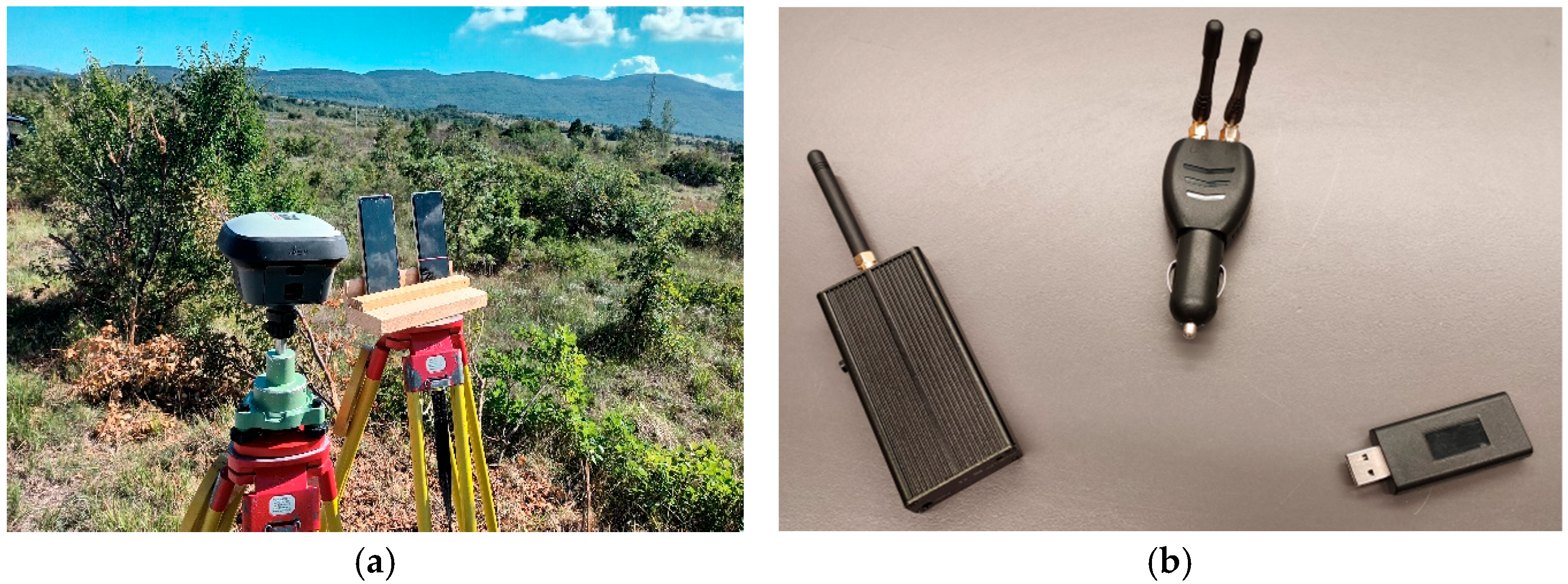
Four double-frequency smartphones were tested along with two Leica GS18 and two Leica GS15 receivers (Figure 1). The basic characteristics for the smartphones are given in Table 1. Additionally, a Leica Viva TS16 SmartPole, i.e., a combination of a GNSS Leica 15 receiver, a 360° prism and a tachymeter TS16, was used to determine the jammer’s position during a walking experiment.
Table 1 lists some basic characteristics for the smartphones used in the experiment. All of them were multi-constellations, making it possible to receive GPS (L1, L5), GLONASS (G1), Galileo (E1, E5a), and BeiDou (B1) signals. Additionally, the Huawei P40 also received B1I, B1C, and B2a BeiDou signals.
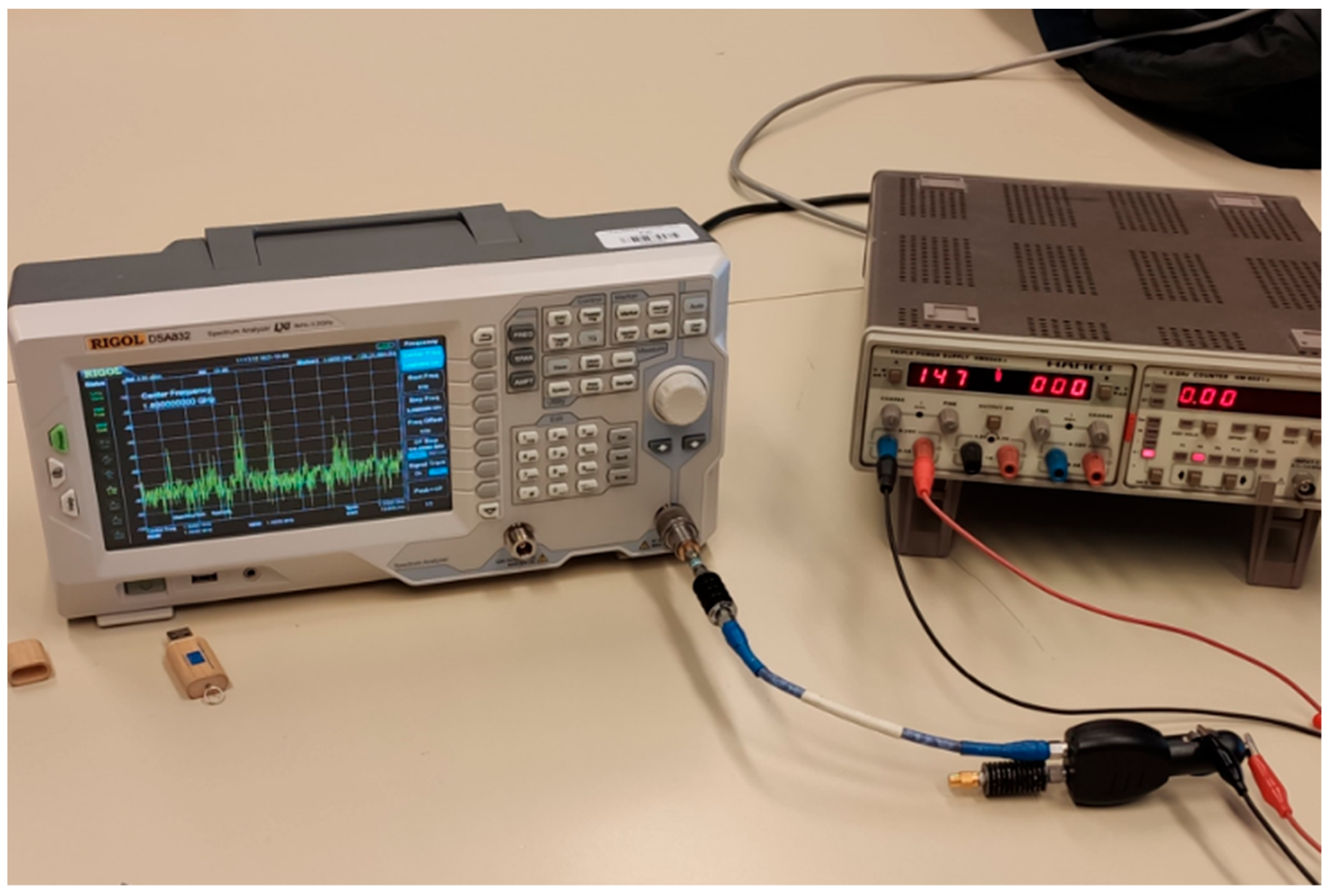
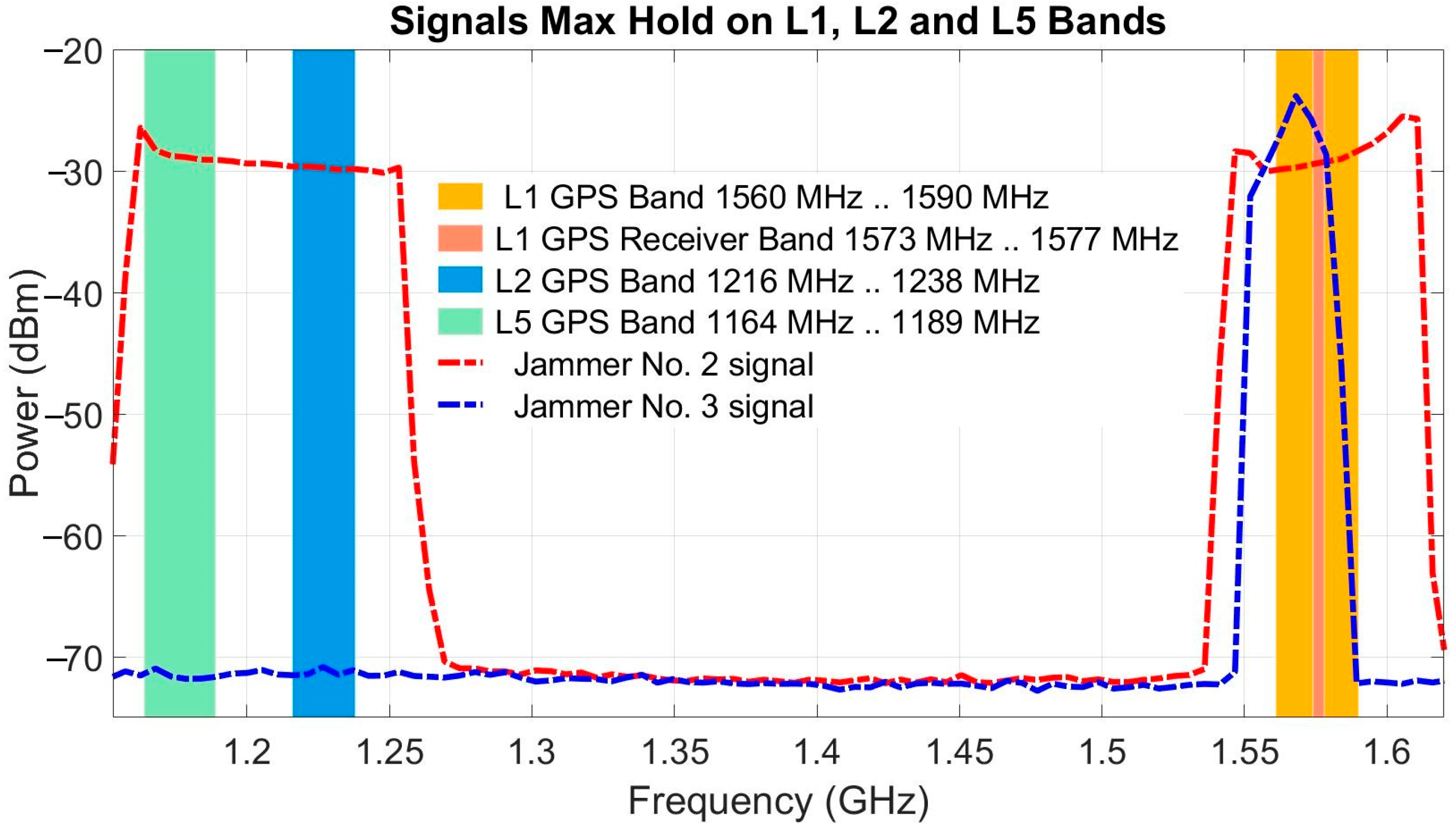
The jamming actions were performed with three different devices, listed in Table 2, shown by their consecutive numbering from left to right (Figure 1b). In which part of the frequency band each jammer interferes with the assigned signals, while sweeping the observed band, is shown by the signal output power of the jammer as a function of the frequency. The experimental setup for measuring the output power of jammer 2 at port L1 via a cable and a 10-dB coaxial attenuator is shown in Figure 2; port L2 was terminated with a dummy load. After a similar experiment for L2, the output signals recorded at ports L1 and L2 were summed. Jammer 3 does not have a SMA port, so its output power had to be measured with a non-attenuated trapping antenna next to the jammer housing. The results of both jammers are shown in Figure 3. The spectrum of the peak power for the output of jammer 1 was already presented in [6].
2.2. Study Area
As with many previous jamming experiments, the area near the village of Črnotiče, Slovenia (B = 45.537°N, L = 13.894°E), established in 2015, served as the test site for the current study (Figure 4). The test site is in a remote area with minimal impact on users. It is suitable because there are no elevated obstacles or tall vegetation near the GNSS receivers that could interfere with the reception of the GNSS signal; there is almost no traffic; and the straight road allows vehicles to travel at a constant speed. Most importantly, the use of all jammers was approved by the Agency for Communications Networks and Services of the Republic of Slovenia (AKOS).
A preliminary test of the effects of jamming on the Xiaomi Mi8 smartphone was conducted in 2021 at the same site to determine the robustness of the geodetic receivers and u-bloxes to chirp L1/E1 jamming [6]. In the time leading up to the present study, we added newer-generation jammers and smartphones. In an initial test, the Xiaomi Mi8 smartphone was installed in the vehicle while the jammer was statically positioned at the roadside. From our experience in 2021, we found that positioning the smartphone on the car’s dashboard was inappropriate. This was confirmed by the studies of Shingal and Bisnath [29]. Therefore, in these new experiments, all the tests were conducted outdoors in open-sky conditions.
3. Setup and Measurement Campaign
The outdoor GNSS measurements were taken on two consecutive days in September 2022, on 19 September 2022 (day-of-year 262; from now on DOY 262) and on 20 September 2022 (DOY 263) at the same site (Figure 5). The reason for the two-day experiments with multiple repetitions of the jamming measurements was redundancy, but also, we believed that, after the first day, something might have gone wrong with the observation reception of the Samsung S20 smartphone. It is well known that smartphones often have problems with system settings when collecting GNSS data, which can also affect the loss of observations. Therefore, specifically for this jamming experiment, where observation loss was commonplace, we tried to ensure that all the smartphones were in observation receiving mode during the measurements and that the app was always open during the experiments. However, despite constantly monitoring what was happening in the Geo++ application, we could not be sure that the storage of observations was working smoothly. The Geo++ RINEX Logger app version 2.1 was used on all the smartphones to store the raw observations.
3.1. Driving Experiments from DOY 262
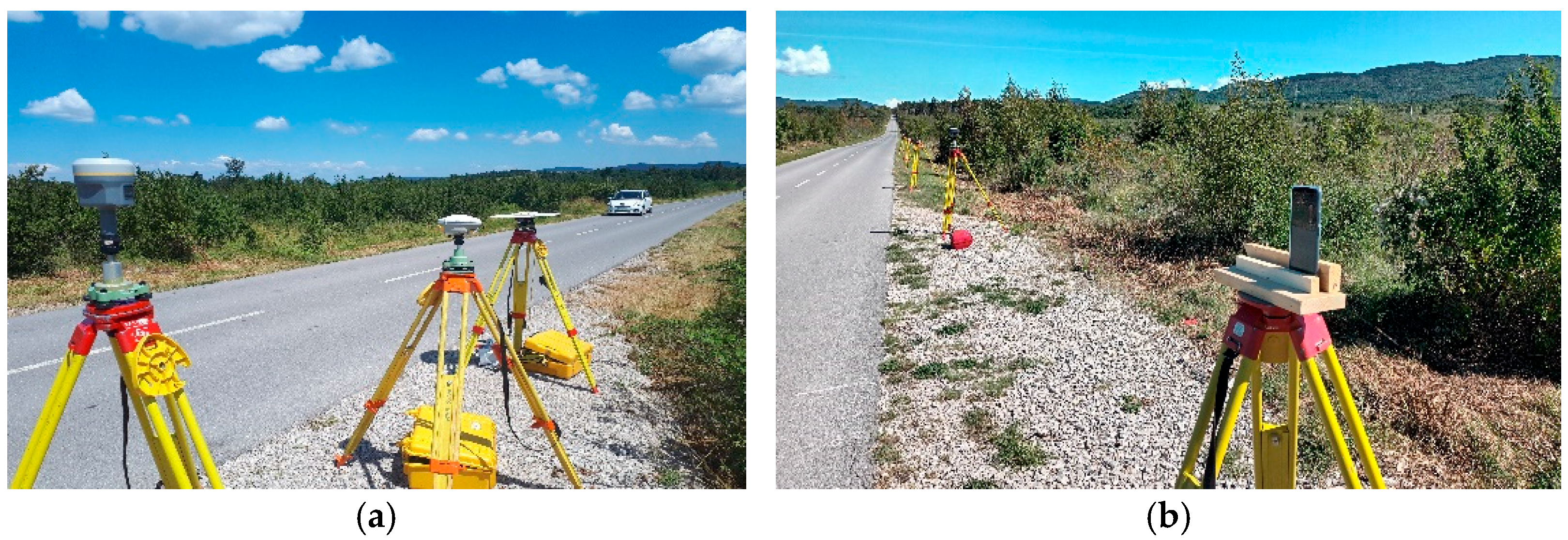
On DOY 262, two sessions, called S1 and S2, were conducted, the first with simultaneous reception of the geodetic receivers and smartphones, and the second with smartphones only. In the first scenario, two receivers, one geodetic and one smartphone, were placed next to each other at each location, as shown in Figure 1 and Figure 4a (locations from A to D). The settings of the receivers and smartphones at each site are listed in Table 3 and Table 4. Already in the first session, some problems with the Samsung S20 were observed. These were due to the system settings; the same was true for the second session. Since the observations were processed immediately after the experiments, we decided to run the test on the next day, with some improvements.
Two sessions, i.e., Session 1 and Session 2, were conducted on DOY 262, the first with simultaneous reception of the geodetic receivers and smartphones, the second with smartphones only. In the first scenario, two receivers, one geodetic and one smartphone, were placed next to each other at each site, as shown in Figure 1 and Figure 5a (locations from A to D). The settings of the receivers and smartphones at each site are shown in Table 3. Already during the first session, some problems were observed with the Samsung S20, which were due to the system settings; the same was true for the second session. Since the observations were processed immediately after the experiments, we decided to run the test on the next day, with some improvements.
The coordinates of the receivers (Slovenian realization of the ETRS89 coordinate system, by using SLOVRP2016/Koper geoid model to compute the normal heights) were determined in advance using a relative static method with respect to a reference point of the Slovenian continuously operating GNSS reference network, SIGNAL.
In all experiments, the geodetic receivers and smartphones were placed statically along the road, while the jammers were installed in the vehicle and used in kinematic mode. The vehicle passed the receivers several times at a constant speed, i.e., “driving scenarios” (Figure 6b). The times of each drive are shown in Table 4 for Session 1 of DOY 262 and in Table 5 for Session 2 of DOY 262.
3.2. Jamming Experiments from DOY 263
On DOY 263, the first session was conducted differently, with the jammer on the pole carried by a walking person (“walking experiment”) (Figure 6a).
Receivers were placed in the same locations for day DOY 263 (sites 1–6) as for DOY 262, as shown in Figure 4b. In the first session of DOY 263, the walking scenario of jamming was conducted to determine the positions of the jammers for each time stamp using the total station. The placement of the device types for each site is shown in Table 1, and the receivers for each site are listed in Table 6.
The coordinates of the jammers were determined in advance using a relative static method with respect to a reference point of the Slovenian continuously operating GNSS reference network, SIGNAL. In the walking scenario, the jammer was attached to a pole directly under the 360° prism, the positions of which were determined using the tachymeter positioning system (TPS). Since positioning during the jamming was undertaken using a total station, this allowed the position of the jammer and, in addition, the distances between the receivers and the jammer to be accurately determined at certain times. In the driving scenario, the jammers were installed in a vehicle that repeatedly passed the GNSS receivers at a constant speed.
Session 1 was the walking scenario and lasted from 09:24:01 to 09:35:30. While walking, discrete points on the trajectory were determined about every 5 m with the tachymeter, and each of them was occupied for about 5 s (Figure 7). For jammer 1, the coordinates were determined for each occupation, together with the times of the point determination. The jammer positions are shown graphically in Figure 5b, with the measurement beginning at the northernmost point and ending in the south. After the walking scenario, there were two sessions, i.e., Session 2 and Session 3, as driving scenarios, with the jammers alternating between four successive runs (Table 7 and Table 8).
4. Processing Observations and Analyses
4.1. Relative Carrier-Phase Positioning of GNSS Devices
In the field, the smartphones’ positions were tested using a combination of GNSS and a terrestrial positioning technique, where the orientation points were determined with the real-time kinematic (RTK) method. When in the office, the positions were also determined from postprocessing, to confirm that the coordinates of the smartphones were determined accurately in the field. Then, we assumed that all the smartphones had chipsets in the upper left-hand corner.
For relative double-difference positioning of the smartphones and geodetic devices in static mode, the virtual reference station (VRS) in the Slovenian network of continuously operating reference stations was calculated. The observations were processed using both Leica Infinity, ver. 3.4.3 (Leica Geosystems, Heerbrugg, Switzerland), and RTKLIB software (demo5_b34d) [35,36] using all available navigation constellations. The settings used in the processing are listed in Table 9. The coordinates collected in the field and calculated afterwards agreed at the cm level. During the jamming sessions, the coordinates for every second were determined for all the GNSS receivers and smartphones to supply information about the possible deviations of the coordinates due to the presence of the jammer.
4.2. CNR Inspection and Jammer Position Determination
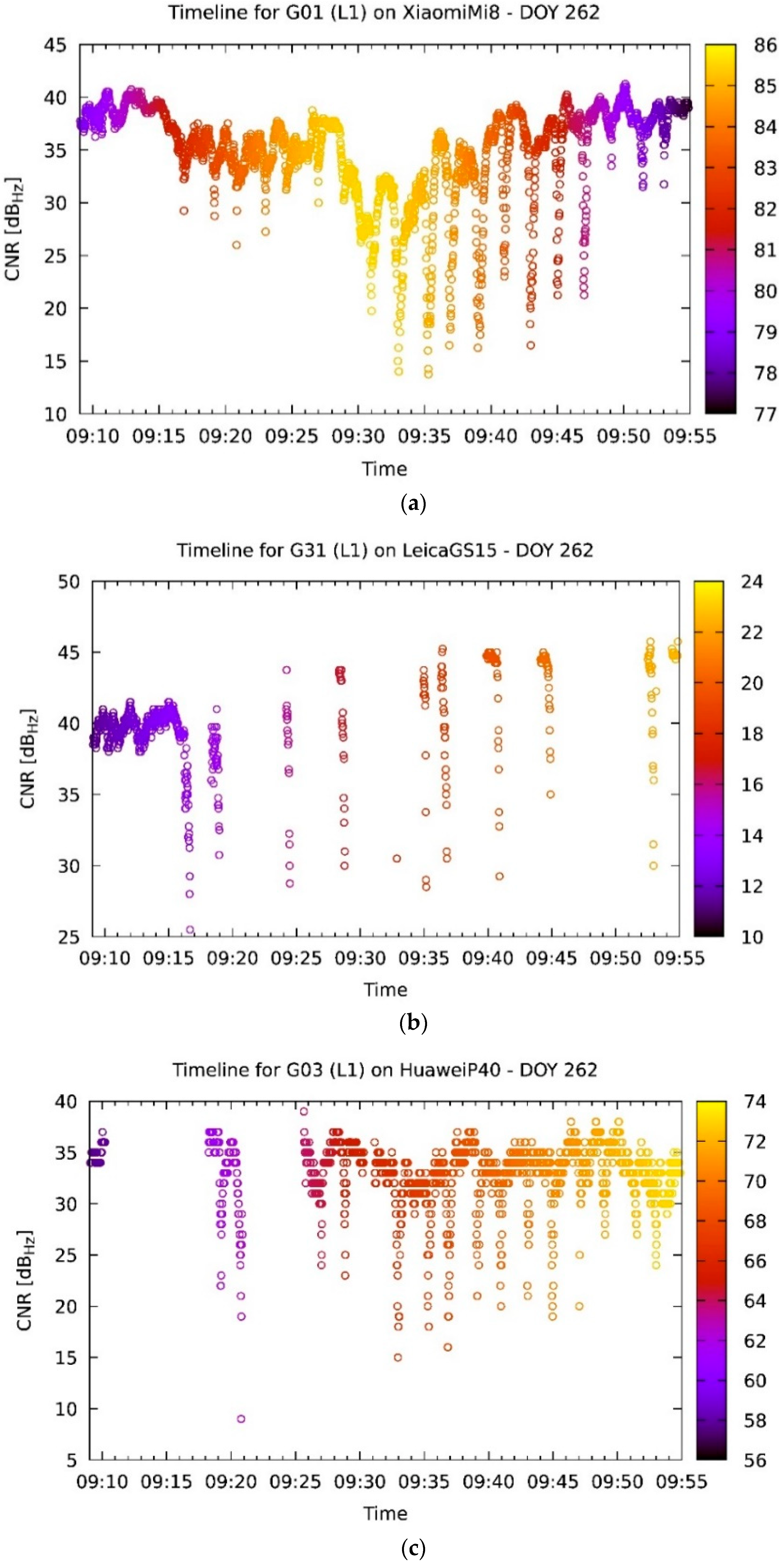
The measurements were first inspected for the CNR time dependence for each of the rides and satellites. Figure 8a,b shows that the CNR acquisition is more continuous on the smartphones, while the geodetic devices typically do not report their CNR measurement when interference is detected. There are, however, some exceptions to the rule (Figure 8c,d). These exceptions are not so much in the sense of observing the opposite, but rather in the sense that the effect is less pronounced.
In their paper, Borio et al. [37] observed the CNR of some commercially available smartphones located beside a road, enabling them to spot the passing of a jammer. This raised the idea of obtaining the current position of the jammer. Since the jammer was inside the car, there was no effective way to directly measure its position via satellite positioning. On the other hand, the speed of the car did not allow us to measure its position using any geodetical means. However, by inspecting the CNR of various satellites and their minima, the time when the jammer was closest to the receiver could be determined.
For the reasons discussed above, only the phones were used for the analysis, since the geodetic receivers did not give enough measurements in the vicinity of the strongest interference. Furthermore, it must be considered that the CNR measurements near the jammer are noisy, so using their minima is not enough for an effective time-of-approach determination. Instead of using the bare minimum of an acquired set of measurements, it would be better to fit the data to an intended function and then use the minimum of that function.
In order to find a sensible fitting function, the following reasoning was employed. The baseband CNR is defined as the logarithm of the ratio between the signal power and the noise power density in a 1-Hz bandwidth (in units of Hz) due to the external blackbody radiation as a contribution due to interference effects and thermal noise generated by the receiver itself. Near the jammer, the noise density increases with the contribution of the jammer’s noise density. This can be expressed using the Betz equation [38],
where S is the signal power, N is the background noise power density, and J is the jammer noise power density. If the latter is assumed to decrease quadratically with the distance (assuming isotropic radiation) and the velocity is constant, then a fitting function f can be constructed (after some basic mathematical calculation) as follows:
where a, b, c, and t0 are the fitting parameters, and t is the variable of this function, with t0 being the minimum sought for.
In order to obtain some sensible results, only the satellite and receiver combinations that gave satisfactory results (for instance, as in Figure 8a) were used. This required a manual inspection of all the acquired data, after which the following selection was made.
The fitting itself was performed using the Levenberg–Marquardt method with non-imposed boundaries on parameters for the least-squares calculation. After finding the proper fitting function for all the combinations in Table 10, a further manual selection of good fits was performed. This had to be done, because not all fits gave satisfactory results. While most fits went well (see, e.g., Figure 9a), in some cases the fitting failed. Sometimes there were not enough measurements near the jammer (as in Figure 9b) to give enough weight to the region of interest and the function fitted accordingly. In other cases, the non-jammed CNR was itself unstable, so the algorithm tried to fit that dependency instead of the jammer-induced variation (Figure 9c).
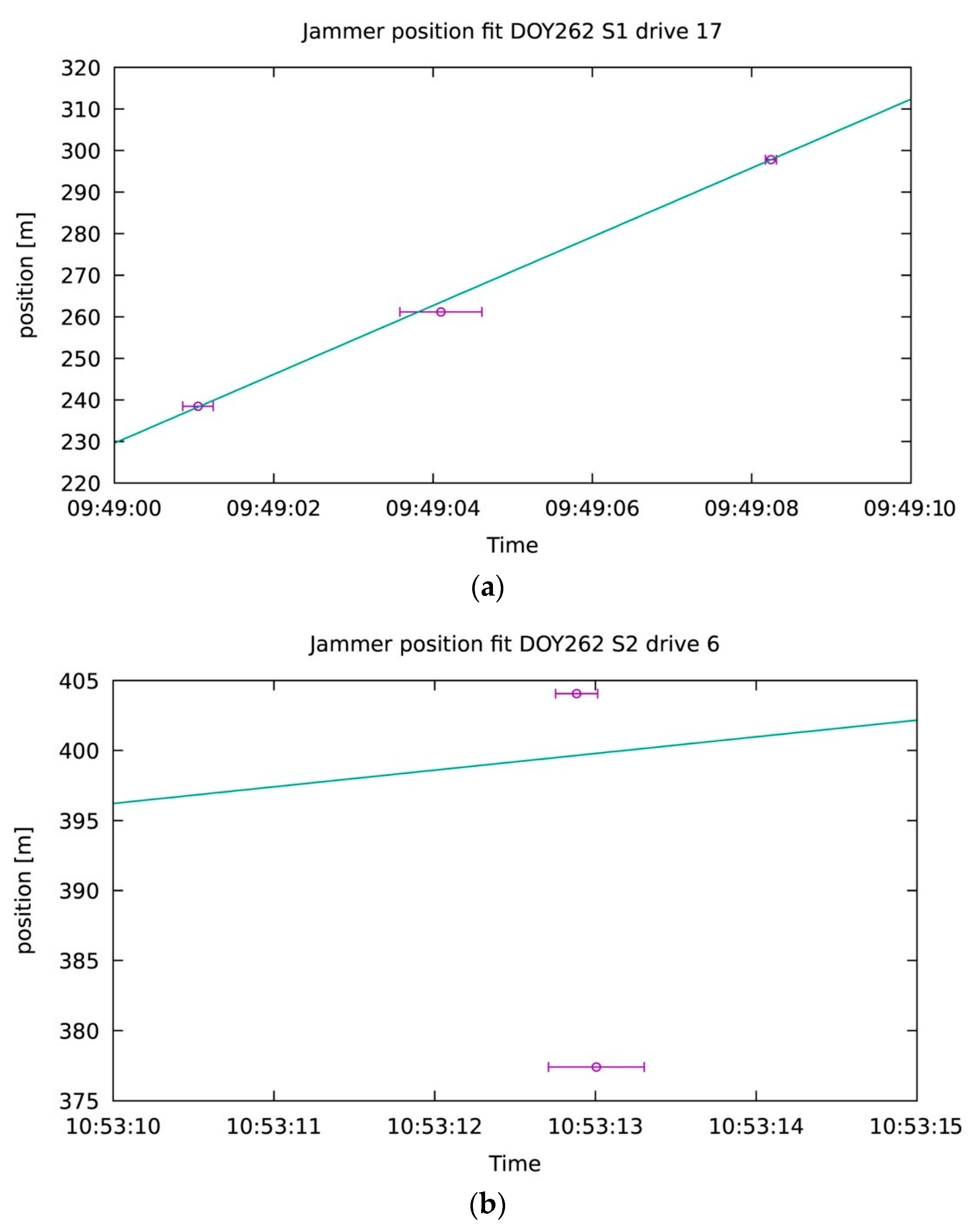
After the elimination of the bad fits, the average t0 of all the satellites was calculated for each of the rides. Since the position of the receivers was known and the road section was straight, it was possible to calculate the closest point on the road to the receiver (for that purpose, the middle of the driving lane was assumed for the jammer’s position). In such a way a few points where the jammer’s position and time were known could be determined. Assuming the speed of the jammer was known, it was possible to reconstruct the path of the jammer for most rides by fitting a linear function to those points. Again, the Levenberg–Marquardt method was used, but this time the points were weighted such that the spread of the time of approach obtained by all the satellites and the number of satellites used for the calculation were considered like this:
where w is the weight for a particular point, s is the spread of the time of approach over all satellites involved in the calculation, and n is the number of satellites. The motivation for such a choice is that the smaller the standard deviation, the more accurate is the time of approach. It was also considered that the deviation of many measurements drops as the inverse square root of their number. Most fits gave satisfactory results (e.g., Figure 10a), yet some did not (e.g., Figure 10b). The latter were discarded from further investigations.
5. Results and Discussion
5.1. Effect of Jammer’s Proximity to CNR
Once the jammer’s position was obtained, the analysis of how the proximity of a jammer can affect a receiver’s signal reception was possible. After inspecting the behavior of the CNR at the jammer approaching, the effect of the jammer on the receivers can be divided into three groups. As mentioned in the previous sections, the GNSS boards inside the smartphones reported the CNR almost continuously (Figure 11a). The two Leica GS15 receivers, instead, stopped reporting their CNR when the jammer interference was too strong, and they gave confused reporting even when the jammer was distanced from them (Figure 11b). The two Leica GS18 receivers had a similar behavior, except that they did not stop reporting completely, but instead gave fewer reports (Figure 11c). Although the figures show only a single satellite and a single jammer, the above findings can be considered as general.
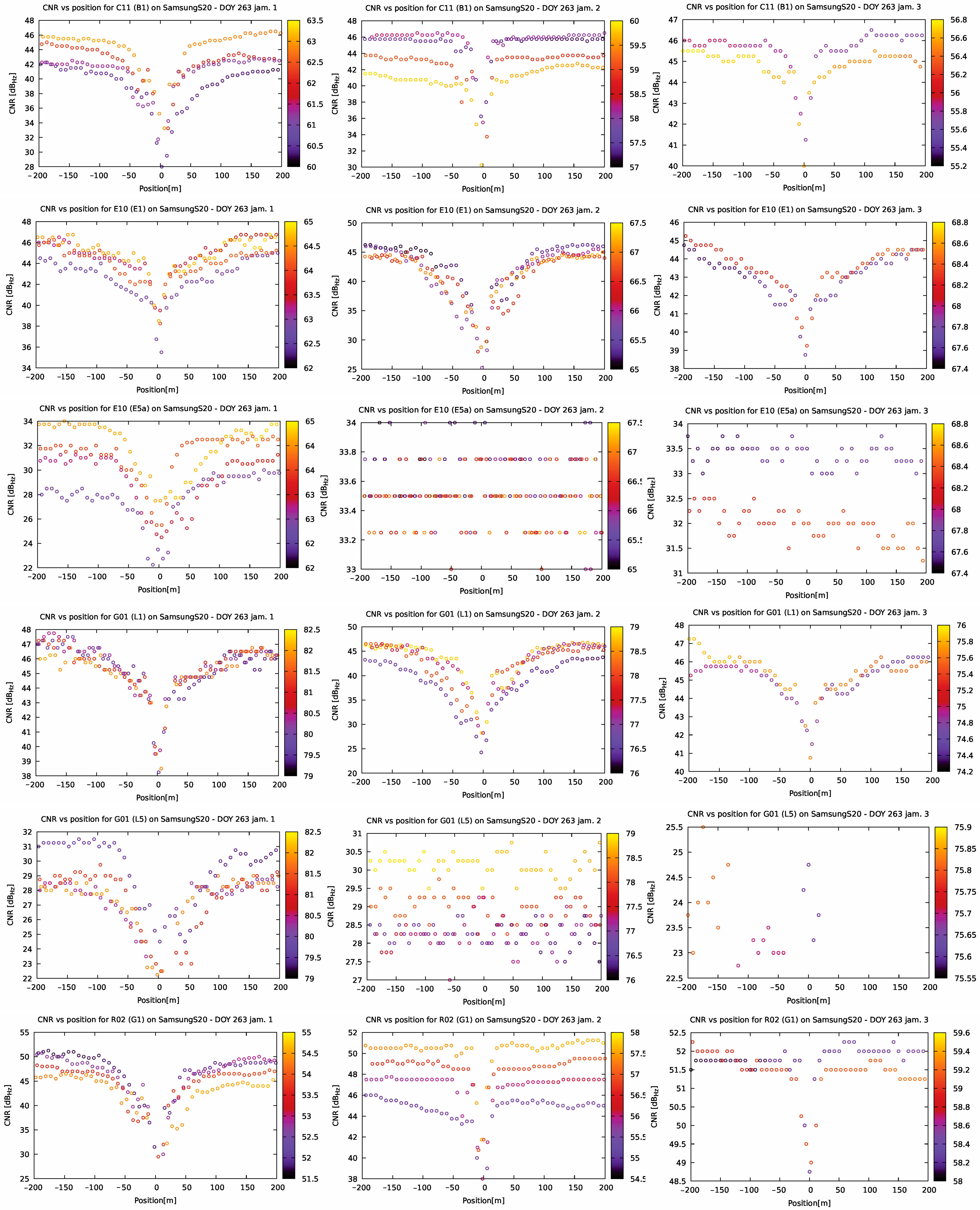
Figure 12 shows how various jammers affect different signals from various satellites. The BeiDou satellites transmitting on B1 are mostly affected by the jammer J1, J2 affects the signal much less, while J3 has barely any effect, only in close proximity and in a much weaker fashion. The E1 Galileo signal is mostly affected by J2, less by J1 and J3. However, on E5a, J2 and J3 have almost no effect. J1, on the other hand, does. The same conclusion holds for GPS, with L1 having a similar dependency to E1 and L5 to E5a. The GLONASS satellite signals behave in the same fashion as the BeiDou signals.
5.2. Effect of Jammer on Precision
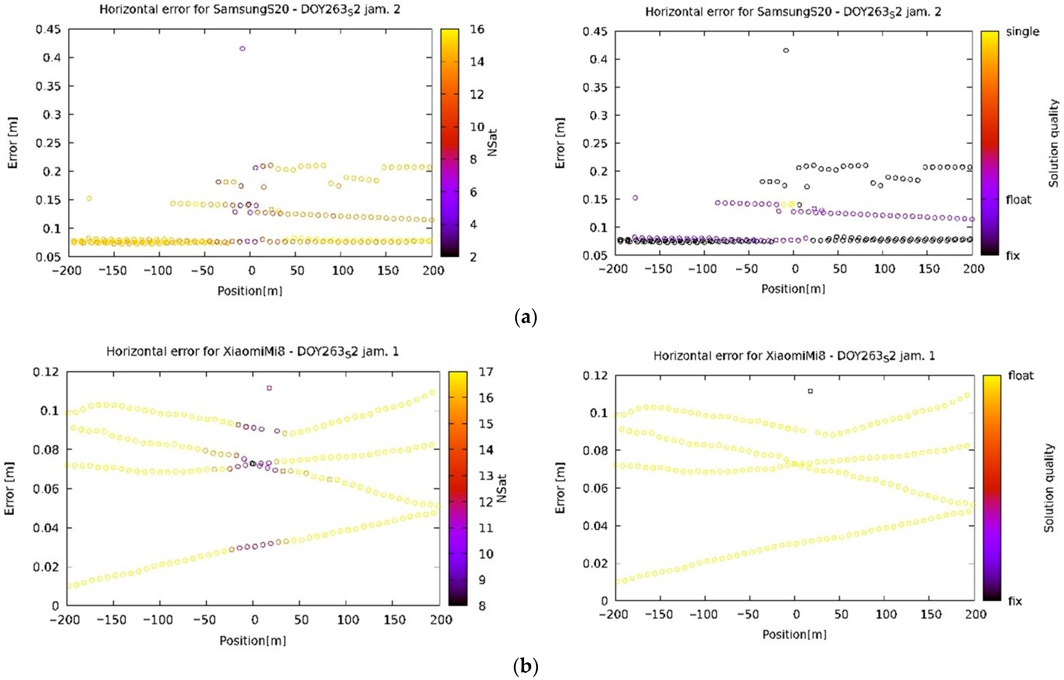
The most interesting part of this research was the ability of the receivers to effectively calculate their position, regardless of the jammer’s presence. As shown in Figure 13a (Leica GS15) and 13b (Leica GS18), the geodetic receivers generally give a better position or do not report any position at all, although the Leica GS18 can recover faster. Note, however, that the latter uses fewer satellites after recovery (Figure 13b). On the other hand, the phones continue to report their position. However, their accuracy is reduced due to the use of fewer satellites (Figure 14a), or they become confused (as in the case of Figure 14b).
In terms of position-quality reporting, the phones generally give much worse results. Even if the geodetic receivers sometimes provide a wrong fix solution (Figure 13b on the right, between −200 and −130 m), probably due to a full period phase mismatch corresponding to the wavelength (approx. 20 cm), it is more likely that a smartphone will get a wrong fix solution (again in the same range, or its multiple) beside wrong float solutions, which are not as problematic on their own, as the end user is expecting them not to be accurate.
It should also be mentioned that the receivers are not always the reason for a solution miscalculation. In fact, in the case of one measurement on the Huawei P40 (however, not confined to it) the software used to process the acquired data was the source of the false positioning. We preferred to use the RTKLIB for data processing, since it is open source and gives the solution quality and the number of satellites involved in the calculation. However, as can be seen from Figure 15, the calculation is completely wrong. When different software was used (Leica Infinity), the results were much closer to the real position, although still unusable for an accurate position determination. Although the differences between both below the centimeter scale were observed for all the calculations, Leica Infinity gave much better results in those few cases when the calculated position was scattered significantly. This type of behavior was observed only when the receiver was a smartphone and never on a geodetic receiver.
5.3. Comparison of Walking and Driving Jamming Experiments
While initially the walking experiment was meant to validate the method for the jammer position calculation, it was lately observed that the jammer’s movement was too slow to effectively identify the CNR minimum. However, the results obtained from the measurements of the CNR and the position error with respect to the jammer’s position do not differ significantly from the measurements when the jammer was being driven in a car.
6. Conclusions
Dual-frequency smartphones and geodetic GNSS receivers were analyzed in different jamming conditions. The objectives of this study were to analyze the differences between the geodetic receivers and double-frequency smartphones on the quality of observations under severe interference and to evaluate the positioning performance of all the devices in difficult conditions for positioning.
The first objective was to understand the main factors affecting the signal reception of smartphones under jamming conditions and to compare their responses with those of professional geodetic receivers. However, the main objective was to show the usefulness of smartphones in localizing jammers.
Using the algorithm and the response of smartphones placed statically along the road, the localization of the jammer was tested for different devices. In addition, an analysis of the relative carrier-phase positioning for the smartphones and geodetic receivers was performed to gain insight into their robustness in accurately determining position during chirp jamming events. The results from this study led us to the following conclusions:
- Carrier-phase smartphones continued receiving data even in high interference scenarios when the geodetic receivers failed.
- The quality of positioning under jamming conditions deteriorated a great deal for the smartphones.
- Various jammers have different effect on the signals from different constellations.
- There is a significant discrepancy between the results obtained using RTKLIB and Leica Infinity software when the results are inconsistent with the real position.
It can be concluded that smartphones have an advantage over professional geodetic receivers in jamming localization because they can receive signals from satellites even under jamming conditions; in such cases, geodetic receivers cancel the measurements to avoid incorrect positioning. However, it is important to remember that there is a lot of mispositioning in such cases and that only the CNR values of the GNSS receivers should be relevant for locating the interfering transmitter.
Since the current study verified the localization of jammers using smartphones placed statically at the roadside, we are left with a major challenge for the future, which is to localize a jammer using devices operating in kinematic mode. Another important future evolution of this study may include the use and testing of hardware and software filters on professional GNSS receivers to mitigate interference effects, increase CNR values, and analyze the effects on positioning accuracy.
Furthermore, the methods used in this study could be a starting point for an automated jammer-localization algorithm. This could be achieved in real time without any postprocessing software, since the CNR measurements can be obtained by other means, for instance, by inspecting the corresponding NMEA sentences (GSV in particular) that all the GNSS chipsets are able to provide.
Author Contributions
Conceptualization, P.P.-P., M.B. and F.D.; method, P.P.-P., M.B. and F.D.; software and validation P.P.-P. and M.B.; formal analysis, P.P.-P. and M.B.; field tests: P.P.-P. and M.B; writing—original draft preparation, P.P.-P., F.D. and M.B.; writing—review and editing, P.P.-P., M.B. and F.D.; visualization, M.B. and P.P.-P.; project administration, P.P.-P. and F.D. All authors have read and agreed to the published version of the manuscript.
Funding
The authors acknowledge the financial support of the Slovenian Research Agency (research core funding No. P2-0227 Geoinformation Infrastructure and Sustainable Spatial Development of Slovenia, and No. P2-0394, Modelling and Simulations in Traffic and Maritime Engineering).
Institutional Review Board Statement
Not applicable.
Informed Consent Statement
Not applicable.
Data Availability Statement
The data that support the findings of this study are openly available at https://gnss.fpp.uni-lj.si/2022-09-19_20, accessed on 20 November 2022. Other data can be available on request from the corresponding author.
Acknowledgments
All the tests conducted in this study were authorized by the Agency for Communication Networks and Services of the Republic of Slovenia (AKOS), whose support is greatly acknowledged. The jammers were characterized at the Laboratory of Radiation and Optics (LSO) of the Faculty of Electrical Engineering of the University of Ljubljana, whose team the authors thank for their support. The three smartphones, Xiaomi 11T, Huawei P40, and Samsung S20, were provided by Telekom Slovenije d.d., for whose help and support the authors would like to express their sincere gratitude.
Conflicts of Interest
The authors declare no conflict of interest.
References
- Banville, S.; van Diggelen, F. Precise GNSS for Everyone: Precise Positioning Using Raw GPS Measurements from Android Smartphones. GPS World 2016, 27, 43–48. Available online: https://www.gpsworld.com/innovation-precise-positioning-using-raw-gps-measurements-from-android-smartphones/ (accessed on 10 December 2022).
- EU Agency for the Space Programme (EUSPA). White Paper on Using GNSS Raw Measurements on Android Devices; European GNSS Agency: Luxembourg, 2017; ISBN 9789292060336. Available online: https://www.euspa.europa.eu/system/files/reports/gnss_raw_measurement_web_0.pdf (accessed on 6 December 2022).
- Malkos, S. Google to Provide Raw GNSS Measurements: GPS World. Available online: https://www.gpsworld.com/google-to-provide-raw-gnss-measurements/ (accessed on 29 September 2022).
- Bažec, M.; Dimc, F.; Pavlovčič-Prešeren, P. Evaluating the vulnerability of several geodetic GNSS receivers under chirp signal L1/E1 Jamming. Sensors 2020, 20, 814. [Google Scholar] [CrossRef] [PubMed] [Green Version]
- Pavlovčič-Prešeren, P.; Dimc, F.; Bažec, M. A comparative analysis of the response of GNSS receivers under vertical and horizontal L1/E1 chirp jamming. Sensors 2021, 21, 1446. [Google Scholar] [CrossRef] [PubMed]
- Dimc, F.; Pavlovčič-Prešeren, P.; Bažec, M. Robustness against Chirp Signal Interference of On-Board Vehicle Geodetic and Low-Cost GNSS Receivers. Sensors 2021, 21, 5257–5276. [Google Scholar] [CrossRef] [PubMed]
- Miralles, D.; Akos, D.M.; Lee, D.K.; Konovaltsev, A.; Kurz, L.; Lo, S. Robust Satellite Navigation in the Android Operating System using the Android Raw GNSS Measurements Engine and Location Providers. In Proceedings of the 2020 European Navigation Conference (ENC), Dresden, Germany, 23–24 November 2020; pp. 1–12. [Google Scholar] [CrossRef]
- Spens, N.; Lee, D.K.; Nedelkov, F.; Akos, D. Detecting GNSS Jamming and Spoofing on Android Devices. Navig. J. Inst. Navig. 2022, 69. [Google Scholar] [CrossRef]
- Kurum, M.; Gurbuz, A.C.; Nelson, C.; Orsini, L.; Scheider, M. On the Feasibility of Smartphone-Based Interferometric GNSS Reflectometry. In Proceedings of the ION 2019 Pacific PNT Meeting, Honolulu, HI, USA, 8–11 April 2019; pp. 635–640. [Google Scholar] [CrossRef]
- Benvenuto, L.; Dabove, P.; Ferrando, I.; Sguerso, D. Preliminary results on tropospheric ztd estimation by smartphone. Remote Sens. 2021, 13, 4567–4589. [Google Scholar] [CrossRef]
- Xu, L.; Zha, J.; Li, M.; Yuan, Y.; Zhang, B. Estimation of ionospheric total electron content using GNSS observations derived from a smartphone. GPS Solut. 2022, 26, 138. [Google Scholar] [CrossRef]
- Li, G.; Geng, J. Characteristics of raw multi-GNSS measurement error from Google Android smart devices. GPS Solut. 2019, 23, 90. [Google Scholar] [CrossRef]
- Robustelli, U.; Paziewski, J.; Pugliano, G. Observation quality assessment and performance of GNSS standalone positioning with code pseudoranges of dual-frequency Android smartphones. Sensors 2021, 21, 2125. [Google Scholar] [CrossRef]
- Paziewski, J.; Fortunato, M.; Mazzoni, A.; Odolinski, R. An analysis of multi-GNSS observations tracked by recent Android smartphones and smartphone-only relative positioning results. Meas. J. Int. Meas. Confed. 2021, 175, 109162. [Google Scholar] [CrossRef]
- Zhu, H.; Xia, L.; Wu, D.; Xia, J.; Li, Q. Study on multi-gnss precise point positioning performance with adverse effects of satellite signals on Android smartphone. Sensors 2020, 20, 6447–6467. [Google Scholar] [CrossRef]
- Benvenuto, L.; Cosso, T.; Delzanno, G. An Adaptive Algorithm for Multipath Mitigation in GNSS Positioning with Android Smartphones. Sensors 2022, 22, 5790–5814. [Google Scholar] [CrossRef]
- Oguntuase, J.O.; Wells, D.; Bisnath, S. Vertical Accuracies of Mass-Market GNSS Receivers and Antennas in Ellipsoid Reference Survey Strategy for Marine Applications. In Proceedings of the Global Oceans 2020: Singapore—U.S. Gulf Coast, Biloxi, MS, USA, 5–30 October 2020; pp. 1–6. [Google Scholar] [CrossRef]
- Robustelli, U.; Baiocchi, V.; Pugliano, G. Assessment of dual frequency GNSS observations from a Xiaomi Mi 8 Android smartphone and positioning performance analysis. Electronics 2019, 8, 91. [Google Scholar] [CrossRef] [Green Version]
- Realini, E.; Caldera, S.; Pertusini, L.; Sampietro, D. Precise GNSS positioning using smart devices. Sensors 2017, 17, 2434–2488. [Google Scholar] [CrossRef] [PubMed] [Green Version]
- Elmezayen, A.; El-Rabbany, A. Precise point positioning using world’s first dual-frequency GPS/galileo smartphone. Sensors 2019, 19, 2593. [Google Scholar] [CrossRef] [PubMed] [Green Version]
- Chen, B.; Gao, C.; Lui, Y.; Sun, P. Real-time Precise Point Positioning with a Xiaomi MI8 Android Smartphone. Sensors 2019, 19, 2835–2849. [Google Scholar] [CrossRef] [Green Version]
- Niu, Z.; Nie, P.; Tao, L.; Sun, J.; Zhu, B. RTK with the assistance of an IMU-based pedestrian navigation algorithm for smartphones. Sensors 2019, 19, 3228–3253. [Google Scholar] [CrossRef] [Green Version]
- Paziewski, J. Recent advances and perspectives for positioning and applications with smartphone GNSS observations. Meas. Sci. Technol. 2020, 31, 091001. [Google Scholar] [CrossRef]
- Angrisano, A.; Gaglione, S. Smartphone GNSS Performance in an Urban Scenario with RAIM Application. Sensors 2022, 22, 786–798. [Google Scholar] [CrossRef] [PubMed]
- Li, Y.; Cai, C.; Xu, Z. A Combined Elevation Angle and C/N0 Weighting Method for GNSS PPP on Xiaomi MI8 Smartphones. Sensors 2022, 22, 2804–2888. [Google Scholar] [CrossRef] [PubMed]
- Zeng, S.; Kuang, C.; Yu, W. Evaluation of Real-Time Kinematic Positioning and Deformation Monitoring Using Xiaomi Mi 8 Smartphone. Appl. Sci. 2022, 12, 435–456. [Google Scholar] [CrossRef]
- Deng, C.; Tang, W.; Cui, J.; Shen, M.; Li, Z.; Zou, X.; Zhang, Y. Triple-frequency code-phase combination determination: A comparison with the Hatch-Melbourne-Wübbena combination using BDS signals. Remote Sens. 2018, 10, 353–371. [Google Scholar] [CrossRef] [Green Version]
- Zeng, W.; Wang, L.; Wang, Y.; Zhang, Z.; Zhang, M. Joint Polarized and Spatial Domain Anti-Jamming Method for GNSS. In Proceedings of the 2013 IEEE International Conference on Signal Processing, Communication and Computing (ICSPCC 2013), Kunming, China, 5–8 August 2013; Available online: https://0-ieeexplore-ieee-org.brum.beds.ac.uk/stamp/stamp.jsp?arnumber=6663946 (accessed on 10 December 2022).
- Shinghal, G.; Bisnath, S. Conditioning and PPP processing of smartphone GNSS measurements in realistic environments. Satell. Navig. 2021, 2, 10. [Google Scholar] [CrossRef] [PubMed]
- Miralles, D.; Levigne, N.; Akos, D.M.; Blanch, J.; Lo, S. Android Raw GNSS Measurements as a New Anti-Spoofing and Anti-Jamming Solution. In Proceedings of the 31st International Technical Meeting of the Satellite Division of The Institute of Navigation (ION GNSS+ 2018), Miami, FL, USA, 24–28 September 2018; pp. 334–344. [Google Scholar] [CrossRef] [Green Version]
- BCM4775X GNSS Receiver with Integrated Sensor Hub. 2017. Available online: https://docs.broadcom.com/doc/12379501 (accessed on 30 December 2022).
- BCM4778. Available online: https://www.broadcom.com/products/wireless/gnss-gps-socs/bcm4778 (accessed on 29 September 2022).
- Snapdragon 855 Mobile Platform|Qualcomm. Available online: https://www.qualcomm.com/products/application/smartphones/snapdragon-8-series-mobile-platforms/snapdragon-855-mobile-platform (accessed on 29 September 2022).
- Qualcomm Snapdragon 855 Plus and 860 Mobile Platform|Snapdragon 855+ Processor for Mobile Gaming. Available online: https://www.qualcomm.com/products/application/smartphones/snapdragon-8-series-mobile-platforms/snapdragon-855-plus-and-860-mobile-platform (accessed on 29 September 2022).
- Takasu, T. RTKLIB: An Open Source Program Package for RTK-GPS. Available online: http://rtklib.com/ (accessed on 4 December 2020).
- Everett, T. RTKLIB Demo5_b34d. Available online: https://rtkexplorer.com/downloads/rtklib-code/ (accessed on 5 May 2022).
- Borio, D.; Gioia, C.; Štern, A.; Dimc, F.; Baldini, G. Jammer Localization: From Crowdsourcing to Synthetic Detection. In Proceedings of the 29th International Technical Meeting of the Satellite Division of The Institute of Navigation (ION GNSS+ 2016), Portland, OR, USA, 12–16 September 2016; Volume 5, pp. 3107–3116. [Google Scholar] [CrossRef]
- Morton, Y.J. Position, Navigation, and Timing Technologies in the 21st Century. In Integrated Satellite Navigation, Sensor Systems, and Civil Applications; Jade Mortin, Y., Ed.; The Institute of Electrical and Electrics Engineering Inc.: Hoboken, NJ, USA, 2021; Volume 1, ISBN 9781119458340. [Google Scholar]
Figure 1.
(a) Leica GS18 receiver and two smartphones setup; (b) jammers used in the experiment.

Figure 2.
Experimental setup for L1 signal power measurement of jammer 2.

Figure 3.
Comparison of peak values, i.e., max hold throughout power spectrums assigned to GPS of jammers 2 and 3.
Figure 3.
Comparison of peak values, i.e., max hold throughout power spectrums assigned to GPS of jammers 2 and 3.

Figure 4.
Test site in Črnotiče, Slovenia: (a) testing professional geodetic receivers in 2019; and (b) simultaneously testing smartphones and geodetic receivers in 2022.
Figure 4.
Test site in Črnotiče, Slovenia: (a) testing professional geodetic receivers in 2019; and (b) simultaneously testing smartphones and geodetic receivers in 2022.

Figure 5.
Test site in Črnotiče, Slovenia: (a) the two-sessions experiments from DOY 262; and (b) experiments from the DOY 263 with jammer’s track in walking scenario.
Figure 5.
Test site in Črnotiče, Slovenia: (a) the two-sessions experiments from DOY 262; and (b) experiments from the DOY 263 with jammer’s track in walking scenario.

Figure 6.
(a) the walking experiment, in which the jammer was attached to the pole directly under the prism and the position of the jammer was determined by TPS; and (b) the driving experiment, in which the jammer was placed in the vehicle.
Figure 6.
(a) the walking experiment, in which the jammer was attached to the pole directly under the prism and the position of the jammer was determined by TPS; and (b) the driving experiment, in which the jammer was placed in the vehicle.

Figure 7.
(a) Session 1 from DOY 263, where the jammer’s positions were determined by TPS; and (b) jammer mounted on the pole just below the 360° prism.
Figure 7.
(a) Session 1 from DOY 263, where the jammer’s positions were determined by TPS; and (b) jammer mounted on the pole just below the 360° prism.

Figure 8.
Time development of CNR for different receivers and satellites with the color of the points representing the satellite elevation: (a) continuous acquisition on a smartphone; (b) typical acquisition on a geodetic device with many blank spots; (c) smartphone with some blank spots; and (d) acquisition on a geodetic device with unusually few (relative to geodetic devices) blank spots; the reasons could be multipath or non-line-of-sight due to vegetation. For other receivers, see https://gnss.fpp.uni-lj.si/2022-09-19 (accessed on 19 February 2022).


Figure 9.
Examples of CNR-fitting functions: (a) a good fit; (b) a bad fit due to a lack of measurements in the vicinity of the jammer; and (c) a bad fit due to the instability of the non-jammed CNR.
Figure 9.
Examples of CNR-fitting functions: (a) a good fit; (b) a bad fit due to a lack of measurements in the vicinity of the jammer; and (c) a bad fit due to the instability of the non-jammed CNR.

Figure 10.
Examples of fitting the path of the jammer to the calculated points: (a) good compliance; and (b) bad compliance.
Figure 10.
Examples of fitting the path of the jammer to the calculated points: (a) good compliance; and (b) bad compliance.

Figure 11.
CNR dependence on the position of the jammer on the road (0 is the point closest to the receiver, a negative value means the jammer is approaching, and a positive value that it is distancing): (a) typical behavior for a smartphone receiver; (b) typical behavior for a Leica GS18; and (c) typical behavior for a Leica GS15. The color of the points represents the satellite elevation.


Figure 12.
CNR dependence on the position of the jammer (see Figure 11 for an explanation) for various jammers (left column J1, middle column J2, and right column J3) and satellites (lines from top to bottom: C11 on B1, E10 on E1, E10 on E5a, G01 on L1, G01 on L5, and R02 on G1) as acquired by a Samsung S20. The color of the points represents the satellite elevation. The plots are provided here for a broad picture only, and the numbers might appear unreadable. For more detailed plots, please visit https://gnss.fpp.uni-lj.si/2022-09-19 (accessed on 19 February 2022).

Figure 13.
Horizontal accuracy for geodetic devices. After the arrival of the jammer in the vicinity of the receiver they either stop reporting their position (case (a)—Leica GS15) or use a smaller number of satellites for the determination (case (b)—Leica GS18).
Figure 13.
Horizontal accuracy for geodetic devices. After the arrival of the jammer in the vicinity of the receiver they either stop reporting their position (case (a)—Leica GS15) or use a smaller number of satellites for the determination (case (b)—Leica GS18).

Figure 14.
Horizontal accuracy for smartphones. Note the horizontal accuracy deterioration and the smaller number of satellites used in the vicinity of the jammer (a). Some phones become completely confused in the presence of the jammer (b).
Figure 14.
Horizontal accuracy for smartphones. Note the horizontal accuracy deterioration and the smaller number of satellites used in the vicinity of the jammer (a). Some phones become completely confused in the presence of the jammer (b).

Figure 15.
Comparison between results given using different software: RTKLIB (left) and Leica Infinity (right).
Figure 15.
Comparison between results given using different software: RTKLIB (left) and Leica Infinity (right).


Table 1.
Some basic characteristics of smartphones used in the experiment.
| Smartphone | Launch | Android | Chipset |
|---|---|---|---|
| Xiaomi Mi8 | 31 May 2018 | Android 8.1 (Oreo) | BCM44775 |
| Samsung S20 | 11 February 2020 | Android 10 | Snapdragon 865 |
| Huawei P40 | 26 March 2020 | Android 10 | Kirin 990 |
| Xiaomi 11T | 15 September 2021 | Android 11 | Snapdragon 888 |
Table 2.
Some basic characteristics of the jammers used in the experiment.
| Jammer | Flag | Label | Interfered GPS Band | Power Source |
|---|---|---|---|---|
| rušička | 1 | VG5007 | L1 | own secondary |
| accu | 2 | 1AN0943 | L1, L2, L5 | cigarette lighter socket |
| usb | 3 | YB-1610200048311 | L1 | USB connector |
Table 3.
Receivers’ setup from DOY 262 at the specific locations shown in Figure 5a.
Table 3.
Receivers’ setup from DOY 262 at the specific locations shown in Figure 5a.
| Site | Session | Receiver | B-Latitude | L-Longitude | H [m] |
|---|---|---|---|---|---|
| A | 1 | Leica GS15 | 45.56389548°N | 13.89417121°E | 434.674 |
| Xiaomi 11T | 45.56389444°N | 13.89417501°E | 435.046 | ||
| B | 1 | Leica GS18 | 45.56375711°N | 13.89405181°E | 434.779 |
| Samsung S20 | 45.56375578°N | 13.89405520°E | 435.008 | ||
| C | 1 | Leica GS15 | 45.56361715°N | 13.89392034°E | 435.025 |
| Xiaomi Mi8 | 45.56361287°N | 13.89392920°E | 435.402 | ||
| D | 1 | Leica GS18 | 45.56344860°N | 13.89375931°E | 435.551 |
| Huawei P40 | 45.56344513°N | 13.89376268°E | 435.610 | ||
| E | 2 | Xiaomi Mi8 | 45.56396017°N | 13.89423794°E | 434.688 |
| F | 2 | Xiaomi 11T | 45.56389605°N | 13.89416995°E | 433.693 |
| G | 2 | Huawei P40 | 45.56375817°N | 13.89405279°E | 435.897 |
Table 4.
Times of drives with different jammers (1, 2, 3); Session 1 of DOY 262.
| Drive | Direction | Velocity [km/h] | Jammer | Start | End |
|---|---|---|---|---|---|
| 1 | Petrinje | 30 | 1 | 09:15:40 | 09:17:30 |
| 2 | Črnotiče | 30 | 1 | 09:18:00 | 09:20:10 |
| 3 | Petrinje | 30 | 1 | 09:20:20 | 09:22:00 |
| 4 | Črnotiče | 30 | 1 | 09:22:10 | 09:24:10 |
| 5 | Petrinje | 60 | 1 | 09:24:20 | 09:25:30 |
| 6 | Črnotiče | 60 | 1 | 09:26:00 | 09:27:50 |
| 7 | Petrinje | 60 | 1 | 09:28:00 | 09:30:00 |
| 8 | Črnotiče | 60 | 1 | 09:30:10 | 09:32:00 |
| 9 | Petrinje | 30 | 2 | 09:32:10 | 09:34:20 |
| 10 | Črnotiče | 30 | 2 | 09:34:30 | 09:36:20 |
| 11 | Petrinje | 30 | 2 | 09:36:30 | 09:38:00 |
| 12 | Črnotiče | 30 | 2 | 09:38:10 | 09:40:20 |
| 13 | Petrinje | 60 | 2 | 09:40:30 | 09:42:00 |
| 14 | Črnotiče | 60 | 2 | 09:42:10 | 09:44:20 |
| 15 | Petrinje | 60 | 2 | 09:44:30 | 09:45:50 |
| 16 | Črnotiče | 60 | 2 | 09:46:00 | 09:48:10 |
| 17 | Petrinje | 30 | 3 | 09:48:20 | 09:50:10 |
| 18 | Črnotiče | 30 | 3 | 09:50:30 | 09:52:30 |
| 19 | Petrinje | 30 | 3 | 09:52:30 | 09:54:10 |
Table 5.
Times of drives in UTC; Session 2 of DOY 262.
| Drive | Direction | Velocity [km/h] | Jammer | Start | End |
|---|---|---|---|---|---|
| 1 | Petrinje | 30 | 1 | 10:42:10 | 10:44:30 |
| 2 | Črnotiče | 30 | 1 | 10:44:40 | 10:46:30 |
| 3 | Petrinje | 30 | 1 | 10:46:40 | 10:48:20 |
| 4 | Črnotiče | 30 | 1 | 10:48:30 | 10:50:20 |
| 5 | Petrinje | 30 | 2 | 10:50:30 | 10:54:10 |
| 6 | Črnotiče | 30 | 2 | 10:54:20 | 10:56:10 |
| 7 | Petrinje | 30 | 2 | 10:56:20 | 10:58:20 |
| 8 | Črnotiče | 30 | 3 | 10:58:30 | 11:00:00 |
| 9 | Petrinje | 30 | 1 | 09:52:30 | 09:54:10 |
Table 6.
Receivers’ setup from DOY 263 at the locations shown in Figure 5b.
Table 6.
Receivers’ setup from DOY 263 at the locations shown in Figure 5b.
| Site | Receiver | B-Latitude | L-Longitude | H [m] |
|---|---|---|---|---|
| 1 | Leica GS18 | 45.56395050°N | 13.89422284°E | 434.750 |
| 2 | Samsung S20 | 45.56386619°N | 13.89414673°E | 434.916 |
| 3 | Huawei P40 | 45.56378458°N | 13.89408466°E | 435.804 |
| 4 | Leica GS18 | 45.56371819°N | 13.89401580°E | 435.079 |
| 4 | Xiaomi Mi8 | 45.56371192°N | 13.89400552°E | 433.894 |
| 5 | Xiaomi 11T | 45.56365512°N | 13.89395938°E | 435.249 |
| 6 | Leica GS18 | 45.56351189°N | 13.89382173°E | 435.408 |
Table 7.
Times of drives with different jammers (1, 2, 3); Session 2 of DOY 263.
| Drive | Direction | Velocity [km/h] | Jammer | Start | End |
|---|---|---|---|---|---|
| 1 | Petrinje | 30 | 1 | 09:39:30 | 09:41:30 |
| 2 | Črnotiče | 30 | 1 | 09:41:40 | 09:43:30 |
| 3 | Petrinje | 30 | 1 | 09:43:40 | 09:45:20 |
| 4 | Črnotiče | 30 | 1 | 09:45:30 | 09:47:00 |
| 5 | Petrinje | 30 | 2 | 09:47:10 | 09:48:20 |
| 6 | Črnotiče | 30 | 2 | 09:48:30 | 09:50:20 |
| 7 | Petrinje | 30 | 2 | 09:50:30 | 09:51:50 |
| 8 | Črnotiče | 30 | 2 | 09:52:00 | 09:53:40 |
| 9 | Petrinje | 30 | 3 | 09:53:50 | 09:55:10 |
| 10 | Črnotiče | 30 | 3 | 09:55:20 | 09:57:20 |
Table 8.
Times of drives with different jammers (1, 2, 3); Session 3 of DOY 263.
| Drive | Direction | Velocity [km/h] | Jammer | Start | End |
|---|---|---|---|---|---|
| 1 | Črnotiče | 30 | 1 | 10:40:00 | 10:41:40 |
| 2 | Petrinje | 30 | 1 | 10:41:50 | 10:43:30 |
| 3 | Črnotiče | 30 | 1 | 10:43:40 | 10:45:20 |
| 4 | Petrinje | 30 | 2 | 10:45:30 | 10:47:10 |
| 5 | Črnotiče | 30 | 2 | 10:47:20 | 10:48:40 |
| 6 | Petrinje | 30 | 2 | 10:48:50 | 10:50:50 |
| 7 | Črnotiče | 30 | 2 | 10:51:10 | 10:52:40 |
| 8 | Petrinje | 30 | 3 | 10:52:50 | 10:54:30 |
| 9 | Črnotiče | 30 | 3 | 10:54:30 | 10:56:00 |
| 10 | Petrinje | 30 | 3 | 10:56:10 | 10:58:10 |
Table 9.
Processing parameters used in RTKLIB.
| Parameters | RTKLIB |
|---|---|
| Constellations | GPS + GLONASS + Galileo + BeiDou |
| Observations | Carrier-phase (L1/E1 + L2/E5b + L5/E5a) |
| Ambiguity | Continuous |
| Ephemeris | Broadcast |
| Elevation angle | 10o |
Table 10.
Used combinations of satellite-receiver for the calculation of the time of approach (C stands for BeiDou, E for Galileo, G for GPS, and R for GLONASS satellites on their respective frequency bands B1, E1, L1, and G1).
Table 10.
Used combinations of satellite-receiver for the calculation of the time of approach (C stands for BeiDou, E for Galileo, G for GPS, and R for GLONASS satellites on their respective frequency bands B1, E1, L1, and G1).
| DOY | Series | Receiver | Used Satellites |
|---|---|---|---|
| 262 | 1 | Huawei P40 | C06 C09 C11 C16 C27 G01 G03 G04 G17 G19 G21 G22 G31 |
| Xiaomi 11T | E04 E05 E09 E34 E36 G01 G03 G04 G17 G19 G21 G22 G31 G32 | ||
| Xiaomi Mi8 | C09 C11 C27 C33 E04 E05 E09 E34 G01 G03 G08 G17 G19 G21 G22 G33 R07 R24 | ||
| 2 | Huawei P40 | C06 C09 C14 C16 C26 C27 E05 E09 E36 G01 G03 G04 G09 G19 G21 G22 G31 | |
| Xiaomi Mi8 | E05 E09 E34 E36 G01 G03 G04 G19 G21 G22 G31 R01 R03 R08 R23 R24 | ||
| 263 | 2 | Huawei P40 | C05 C06 C09 C11 C16 G01 G03 G04 G08 G17 G21 G22 G31 G32 |
| Samsung S20 | C05 C1C C12 C16 C21 C34 E04 E10 E12 E19 E33 G01 G03 G04 G08 G17 G32 R02 R17 | ||
| Xiaomi 11T | E04 E10 E11 E12 E19 G01 G03 G08 G17 G21 G22 G31 G32 | ||
| Xiaomi Mi8 | C09 C11 C12 C21 C28 C34 E04 E10 E19 E33 G01 G03 G04 G08 G17 G19 G21 G22 R01 R02 R23 R24 | ||
| 3 | Huawei P40 | C09 C14 G01 G03 G04 G06 G09 G17 G19 G21 G22 G31 | |
| Xiaomi 11T | C11 C16 C21 C28 C33 C34 E04 E10 E11 E19 G01 G03 G04 G06 G09 G17 G21 G31 | ||
| Xiaomi Mi8 | C09 C11 C21 C26 C28 C33 E04 E19 E33 G03 G19 G21 G22 G31 | ||
| Huawei P40 | C09 C11 C21 C26 C28 C33 E04 E19 E33 G01 G03 G04 G17 G19 G21 G22 G31 R02 R17 |
Disclaimer/Publisher’s Note: The statements, opinions and data contained in all publications are solely those of the individual author(s) and contributor(s) and not of MDPI and/or the editor(s). MDPI and/or the editor(s) disclaim responsibility for any injury to people or property resulting from any ideas, methods, instructions or products referred to in the content. |
© 2023 by the authors. Licensee MDPI, Basel, Switzerland. This article is an open access article distributed under the terms and conditions of the Creative Commons Attribution (CC BY) license (https://creativecommons.org/licenses/by/4.0/).
Share and Cite
MDPI and ACS Style
Pavlovčič-Prešeren, P.; Dimc, F.; Bažec, M. Exploiting the Sensitivity of Dual-Frequency Smartphones and GNSS Geodetic Receivers for Jammer Localization. Remote Sens. 2023, 15, 1157. https://0-doi-org.brum.beds.ac.uk/10.3390/rs15041157
AMA Style
Pavlovčič-Prešeren P, Dimc F, Bažec M. Exploiting the Sensitivity of Dual-Frequency Smartphones and GNSS Geodetic Receivers for Jammer Localization. Remote Sensing. 2023; 15(4):1157. https://0-doi-org.brum.beds.ac.uk/10.3390/rs15041157
Chicago/Turabian StylePavlovčič-Prešeren, Polona, Franc Dimc, and Matej Bažec. 2023. "Exploiting the Sensitivity of Dual-Frequency Smartphones and GNSS Geodetic Receivers for Jammer Localization" Remote Sensing 15, no. 4: 1157. https://0-doi-org.brum.beds.ac.uk/10.3390/rs15041157
Note that from the first issue of 2016, this journal uses article numbers instead of page numbers. See further details here.