
Controlled Growth of Unusual Nanocarbon Allotropes by Molten Electrolysis of CO2

1
Department of Chemistry, George Washington University, Washington, DC 20052, USA
2
C2CNT, Carbon Corp., 1035 26 St NE, Calgary, AB T2A 6K8, Canada
*
Author to whom correspondence should be addressed.
Catalysts 2022, 12(2), 125; https://0-doi-org.brum.beds.ac.uk/10.3390/catal12020125
Submission received: 17 December 2021
/
Revised: 12 January 2022
/
Accepted: 12 January 2022
/
Published: 21 January 2022
(This article belongs to the Special Issue New Trends in Catalysis for Sustainable CO2 Conversion)
Abstract
:This study describes a world of new carbon “fullerene” allotropes that may be synthesized by molten carbonate electrolysis using greenhouse CO2 as the reactant. Beyond the world of conventional diamond, graphite and buckyballs, a vast array of unique nanocarbon structures exist. Until recently, CO2 was thought to be unreactive. Here, we show that CO2 can be transformed into distinct nano-bamboo, nano-pearl, nano-dragon, solid and hollow nano-onion, nano-tree, nano-rod, nano-belt and nano-flower morphologies of carbon. The capability to produce these allotropes at high purity by a straightforward electrolysis, analogous to aluminum production splitting of aluminum oxide, but instead nanocarbon production by splitting CO2, opens an array of inexpensive unique materials with exciting new high strength, electrical and thermal conductivity, flexibility, charge storage, lubricant and robustness properties. Commercial production technology of nanocarbons had been chemical vapor deposition, which is ten-fold more expensive, generally requires metallo-organics reactants and has a highly carbon-positive rather than carbon-negative footprint. Different nanocarbon structures were prepared electrochemically by variation of anode and cathode composition and architecture, electrolyte composition, pre-electrolysis processing and current ramping and current density. Individual allotrope structures and initial growth mechanisms are explored by SEM, TEM, HAADF EDX, XRD and Raman spectroscopy.
1. Introduction
High atmospheric CO2 levels are the largest cause of global warming. Atmospheric CO2 concentration, which had cycled at 235 ± ∼50 ppm for 400 millennia until 1850 and the advent of rising anthropogenic CO2 emissions, is currently at 416 ppm and rising at a rapid annual rate, creating global planetary climate disruptions, habitat loss, and species extinction [1,2,3,4]. To date, international efforts to decrease CO2 emissions have failed. The Earth is in the grips of an existential threat and a mass extinction event generally defined as loss of 75% of planetary species. This emphasizes the critical imperative of alternative pathways of CO2 conversion into another, stable non-greenhouse material (CO2 utilization). CO2 is regarded as such a stable molecule that its transformation into a non-greenhouse material poses a major challenge, as summarized in our NSF workshop on Chemical Recycling and Utilization of CO2 [5].
Graphitic carbon nanomaterials (CNMs) are high value, highly stable (with a graphite-like geologic stability) state-of-the-art materials, which have the potential to be attractive CO2 utilization products. However, conventional methodologies of CNM production have a high CO2 footprint. For example, chemical vapor deposition (CVD) is an energy-intensive, expensive process to produce CNM associated with an unusually massive release, as much as 600 tons of CO2 emitted per ton of CNM product [6]. Despite the attractive properties and application of CNMs, which range from extraordinary strength as materials with the highest ultimate tensile strength to advanced electronic, thermal, electrical storage, shielding and tribological properties, its demand is limited by a high market cost. Due to high CVD production costs, the market price of CNMs is unusually high (USD 100,000 to over USD 1 million per ton). A “green”, rather than high carbon footprint CNT, will increase demand. The use of CO2 as a reactant to generate value-added CNM products will provide motivation to consume this greenhouse gas to mitigate climate change, and its transformation to CNMs can provide a stable material to store carbon removed from the environment.
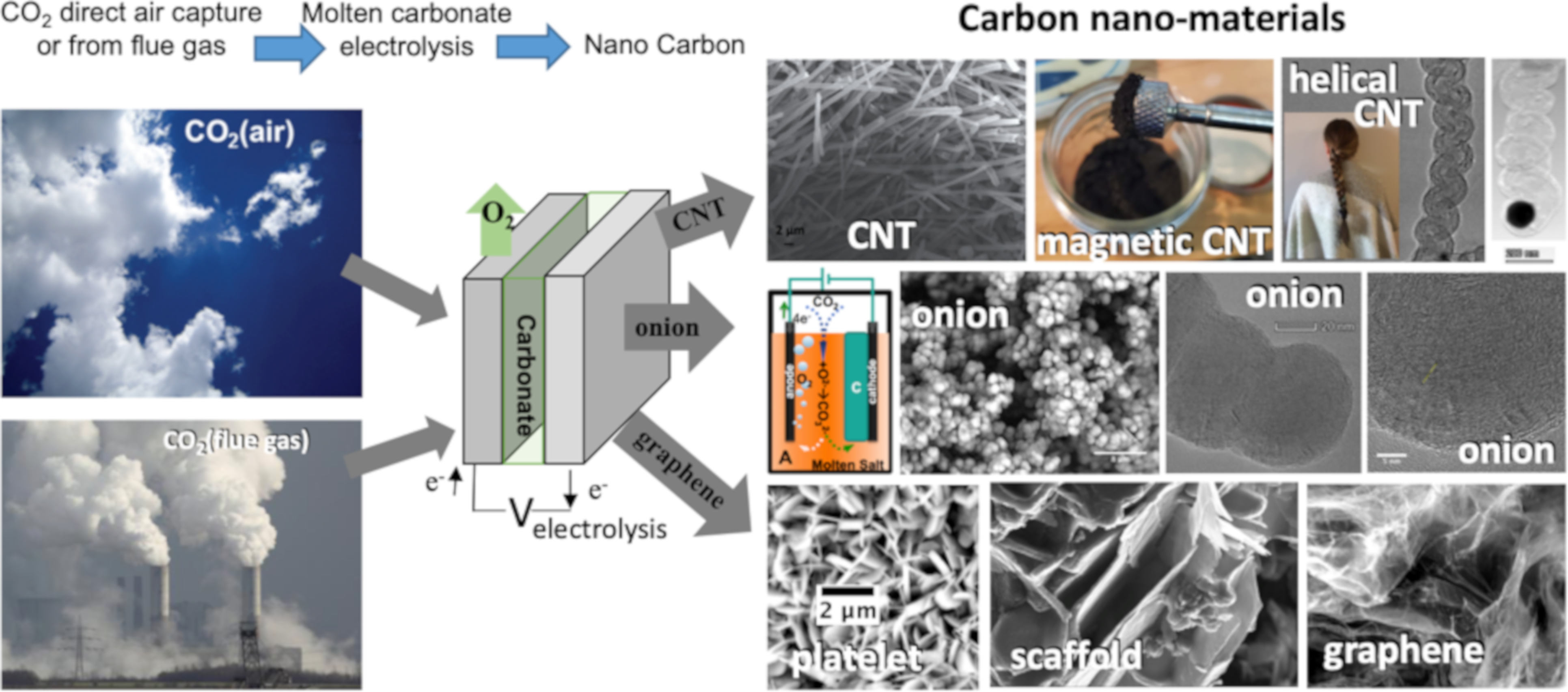
In 2009 (fundamental) and 2010 (experimental), a novel solar driven methodology to split CO2 into C and O2 by molten carbonate electrolysis was demonstrated as a tool to mitigate climate change [7,8]. This molten carbonate process is not limited to sunlight as the electrolysis energy source. It was demonstrated that by using molten carbonate and a variety of electrolytic configurations, the product can be pure CNM, such as CNT [8,9,10,11,12,13,14,15,16,17,18,19,20,21,22,23,24,25,26,27,28,29]. For example, this novel chemistry transforms carbon dioxide to carbon nanotubes (C2CNT process), and as illustrated in Figure 1 directly captures atmospheric CO2, or concentrated anthropogenic CO2, such as from industrial processes. Power plant and cement exhausts have been investigated [23,24], and after a five-year-long international competition, this C2CNT process was awarded the 2021 XPrize XFactor Award for transforming CO2 from flue gas into a valuable product using flue gas from the 860 MW Shepard natural gas power plant (Calgary, AB, Canada) [30,31]. Composites of these high-strength CNTs can be mixed with structural materials, such as CNT-cement, CNT-steel and CNT-aluminum, greatly reducing the carbon footprint of structural materials, and acting to amplify the CNT’s CO2 emission reduction [11]. As presented in Figure 1, several different CNMs can be produced by molten carbonate splitting including: magnetic CNTs [18], thin CNTs [19,29], long CNTs [15,16,29], doped, high electrical conductivity CNTs [13,15,16], high Li-ion anode storage CNTs [22], macroscopic CNT assemblies [29], a novel nanocarbon scaffold [28], graphene and carbon nanoplatelets (CNP) [27], and carbon nano-onions (CNO) [25] and helical CNTs (HCNT) [20]. This study introduces entirely distinct nanocarbon morphologies discovered by systematic variation of the electrochemical parameters of the molten carbonate splitting of CO2. With the exception of a new methodology to form CNOs, there are no overlaps or redundancies with the previous electrolytically formed CNM morphologies that have been discovered.
The wide range of CNM morphologies observed shows the potential for product tuning. Different CNMs have different applications. For example, CNTs are the strongest known and most thermally conductive material along their major axis [32,33]. CNOs can make excellent lubricants and their high surface area and other characteristics make them appealing for batteries or supercapacitors, and they may have uses in refrigerants and in EMF shielding [20,25,34,35,36,37,38,39]. Platelets can contribute to the formation of lightweight and porous, but strong, nano-gels [40,41,42]. HCNTs have strong chiral, magnetic, piezo-electric properties, and may act as nano-springs [43,44,45,46,47,48,49,50,51,52]. Even within the same group, such as CNTs, different lengths, thicknesses, layers of graphene walls, etc. morphologies can have different properties such as differing rigidity or surface areas [15,19,47]. This would incentivize even greater CO2 transformed to removable carbon by allowing products to have access to a wide range of markets, which collectively could increase technological progress and provide a growing demand as a buffer to remove anthropogenic CO2.
The C2CNT process has quantified the high affinity of molten carbonates to absorb both atmospheric and flue gas CO2 levels. It has been shown, utilizing the 13C isotope of CO2 to track the carbon from its origin (CO2 a gas phase reactant) through its transformation to nanocarbon product, that the CO2 originating from the gas phase serves as the renewable C building blocks in the observed CNT product [8,9]. The molten carbonate is not consumed, but renewed, catalyzing the ongoing electrolysis of CO2. The net reaction is:
Dissolution: CO2 (gas) + Li2O (soluble) ⇌ Li2CO3 (molten)
Electrolysis: Li2CO3 (molten) → C (CNT) + Li2O (soluble) + O2 (gas)
Net: CO2 (gas) → C (CNT) + O2 (gas)
An important component of the C2CNT growth process is transition metal nucleated growth. These catalysts lead to clearly observable CNT walls with thick graphene interlayer separations. However, when these nucleation additives are excluded, rather than CNTs, instead high-yield synthesis of CNOs or graphene is accomplished [25,27].
This study systematically explores the possibility to synthesize a variety of new molten carbonate synthesized carbon “fullerene” allotropes, and opens a new world of inexpensive nanocarbons, made from CO2, to be explored as incentivized (valuable) products for the transformation and stable removal of CO2 and climate change mitigation. Here the conventional definition of allotrope of “different physical forms in which an element can exist” is employed, rather than the alternative “structural modifications of an element bonded together in a different manner”. Specifically, this study explores which reactive pathway condition leads to the selection of new nanocarbon allotropes over another and can lead to higher purity products and better formation of a single product
2. Results and Discussion
2.1. Electrolytic Conditions Varied to Synthesize New Nanocarbon Allotropes from CO2
This study varies conditions in which small electrolytic changes in a 770 °C molten Li2CO3 yield major changes to the product consisting of new, non-CNT nanocarbon allotropes. In a parallel study to this new carbon allotropes study, different systematic changes to these same electrolytic parameters have revealed a wide range of electrochemical conditions that synthesize only a high-purity, high-yield product consisting only of various carbon nanotube morphologies. That sister study focuses on the transition metal nucleation zone of CNT growth and also reveals molten electrochemical conditions which produce assemblies of CNTs [29]. Straight CNT type carbon allotropes tended to dominant when either 0.1% wt iron oxide was added or the anode contained a high amount of Fe (Nichrome C: 24%, Inconel 718 18.5%, or Inconel 718 at 18.5%). The electrochemical conditions varied here are composition and/or architecture of the cathode and anode, additives and their concentrations to the Li2CO3 electrolyte, and current density and time of the electrolysis. Electrolyte additives that are varied include Fe2O3 and nickel or chromium powder. Electrolyses are varied over a range of electrolysis current densities. Variations of the electrodes include the use of cathode metal electrodes such as Muntz brass, Monel, or Nichrome alloys. Anode variations include noble anodes such as iridium, various nickel containing anodes including nickel, Nichrome A or C, Inconel 600, 625, or 718, or specific layered combinations of these metals. Alloy composition of the metals used as electrodes is presented in Table 1. Metal variation was further refined by combining the metals in Table 1 as anodes, for example using a solid sheet of one Inconel alloy, layered with a screen or screens of another Inconel alloy, such as an anode of Inconel 625 with 3 layers of (spot welded) 100 mesh Inconel 600 screen.
2.2. Electrochemical Conditions to Synthesize Bamboo and Pearl Nanocarbon Allotropes from CO2
We have conducted several thousands of different electrolyses to split CO2 in molten lithium carbonate. A fascinating, but rarely observed, product which occurred in less than 30 of those many electrolyses had nano-morphology analogous to the macro-structure of bamboo, but had been only observed as a low fraction of the total product. Table 2 summarizes the systematic optimization of electrolysis conditions in 770 °C Li2CO3 to optimize and maximize the electrolytic formation of this nano-bamboo. A few prior electrolyses producing nano-bamboo were associated with nickel electrodes, or started with ramping up of the current to encourage nucleation. Experiment Electrolysis I in the top row of Table 2 includes both these features including nickel as both the cathode and anode, and (not delineated in the table) an initial 10 min electrolysis at a constant 0.01 and then 0.02 A/cm2, followed by 5 min at 0.04 and then 0.08 A/cm2, after which the constant current electrolysis was conducted at the tabulated 0.2 A/cm2. Nano-bamboo was evident in the product SEM, but constituted a minority (30 wt%) of the total product. As seen in Electrolysis II in Table 2, an increase in the nano-bamboo product is achieved with the direct addition of Ni and Cr powders to the electrolyte, and the anode is replaced by a noble metal (iridium) accompanied by a 5-fold decrease in current density. As noted in the table, this Electrolysis II has the first majority, 60 wt%, of the nano-bamboo product. Coulombic efficiency quantifies the measured available charge (current multiplied by the electrolysis time) to the measured number of four electrons per equivalent of C in the product. Coulombic efficiency tends to drop off with current density, and in this case the coulombic efficiency of the synthesis was 79%.
The low current ramping, pre-electrolysis conditions can have benefits and disadvantages. (1) Low current conditions may support the reduction and deposition of initial graphene layers to facilitate ongoing reduction and growth. In addition, lower current can favor transition metal deposition at the cathode and formation of nucleation sites, at low concentrations compared to carbonate (from CO2) in the electrolyte. The analysis of bound versus free metal cations in the molten electrolyte for a reduction potential calculation has been a challenge. Without Nernst activity and temperature correction, the reduction rest potentials of Ni, Fe, Cr and Cu and CO2 at room temperature are CO2(IV/0) = −1.02, Cr(III/0) = −0.74, Ni(II/0) = −0.25, Fe(III/0) = −0.04, and Cu(II/0) = 0.34. Note, however, that the free activity of tetravalent carbon as carbonate C(IV)O32− formed by the reaction of C(IV)O2 with electrolytic oxide in pure molten carbonate solutions is many orders of magnitude higher than the dissolved transition metal ion activity in the electrolysis electrolyte. This helps favor the thermodynamic and kinetic reduction of the tetravalaent carbon, over metal deposition at the cathode. The practical observation is that, for the majority of molten carbonate CO2 electrolyses we have studied, the initial low current ramping is not observed to promote highest purity carbon deposition.
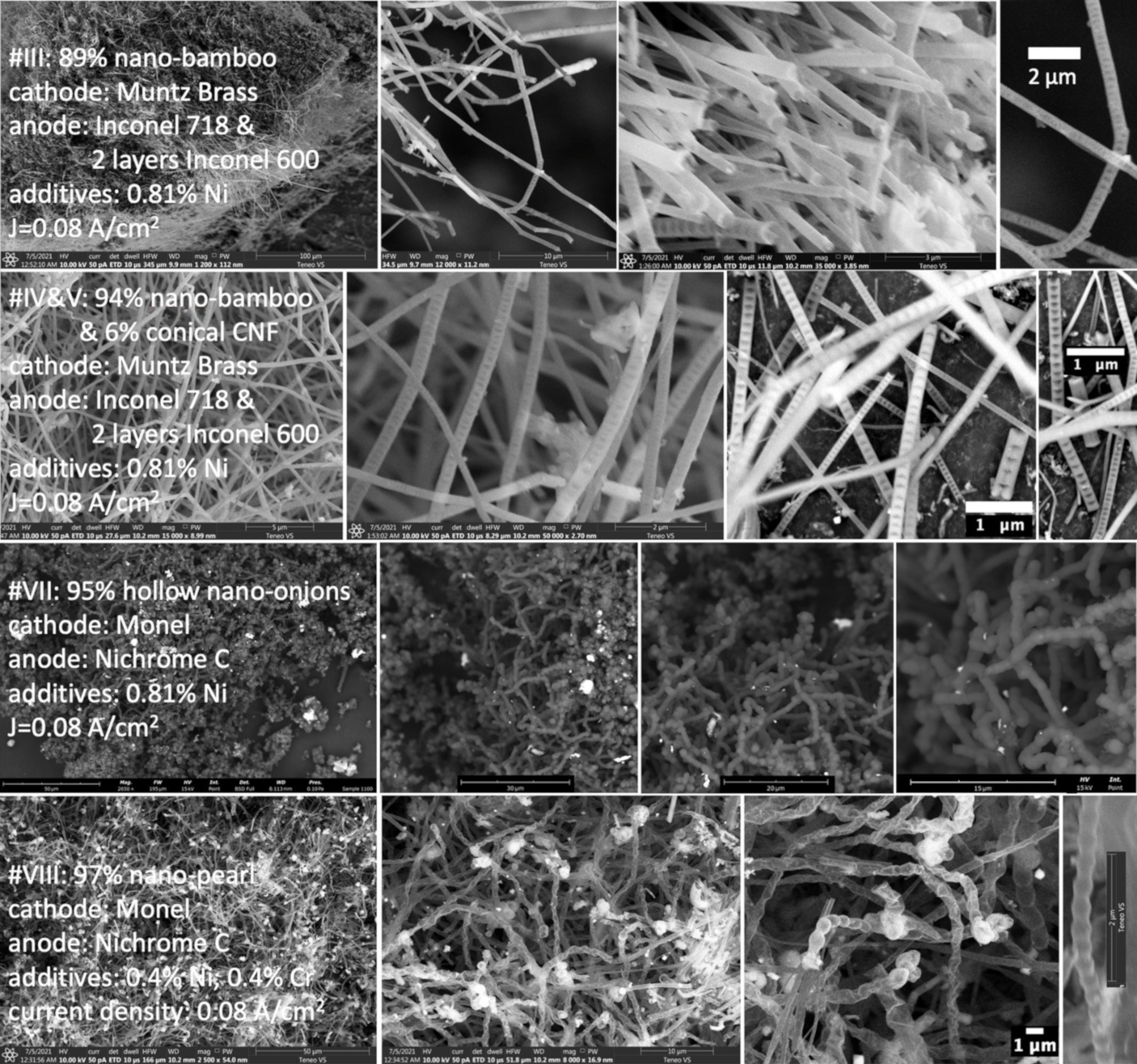
The first row of Figure 2 presents the product SEM of Electrolysis III, which continues to use a low current density, continues to exhibit a coulombic efficiency of 78%, focuses on a Ni powder addition to electrolyte, and refines the anode to Inconel 718 with two layers of Inconel 600, with an increase to 89 wt% the nano-bamboo product. Additionally, this electrolysis used an “aged” electrolyte (not delineated in the table). The freshly molten electrolyte requires time (up to 24 h) to reach a steady state equilibrium (pre-equilibration step) [16,20]. For Electrolysis III, the electrolyte was aged 24 h prior to melting and prior to immersion of the electrodes. However, it was observed that the aging is disadvantageous towards maximizing the nano-bamboo yield. A final refinement, in immediate use of the freshly melted electrolyte (elimination of the aging step), increases the nano-bamboo product to 90 wt% of the product (row 2 in Figure 2, and Electrolysis IV, and repeated as V in Table 2). Interesting, the 6% non-bamboo product in Electrolyses IV and V appears to be conical carbon nano-fiber (CNF) morphology, with its distinctive triangular-shaped voids in the morphology as seen in the second row of Figure 2. A simplified electrolysis eliminates observed CNF impurities resulting in 95% of the nano-bamboo allotorope. This Electrolysis VI is conducted without the current ramp activation at a high 0.4 A/cm2 current density, and exhibits a 99.7% coulombic efficiency. This electrolysis was tailored to have a purposeful excess of nucleation metals accomplished both with the use of Nichrome C electrodes, which contain Ni, Fe and Cr (Table 1), and through the direct addition of Ni and Cr powders to the electrolyte.
The continued use of high concentrations of added transition metal powder to the electrolyte and low current density, but a change of electrodes, yields another distinct nanocarbon allotrope termed here as “hollow nano-onions”. Specifically, in Electrolysis VII in Table 2 and Figure 2, the same concentration of Ni powder that had been used as in Electrolyses VI and V was used, and again the electrolyte was not aged nor were ramped initiation currents applied. However, a Monel cathode and Nichrome C anode were used, resulting in a 95 wt% of the product having a distinctive hollow nano-onions morphology. The hollow nature of the nano-onions will be revealed by TEM, but their spheroid character is seen by SEM in the third row of Figure 2. When the pure nickel electrolyte additive was changed to half nickel and half chromium powder, as summarized in Table 2 for Electrolyses VIII and IX, the product has a distinctive “nano-pearl” morphology with its similarity to a beaded necklace. Here, the product fraction increased to 97% of this nano-pearl carbon and is seen by SEM in the bottom row of Figure 2. Electolyses VII–IX conducted have low J = 0.0 A/cm2 and exhibit a diminished coulombic efficiency of 79 to 80%.
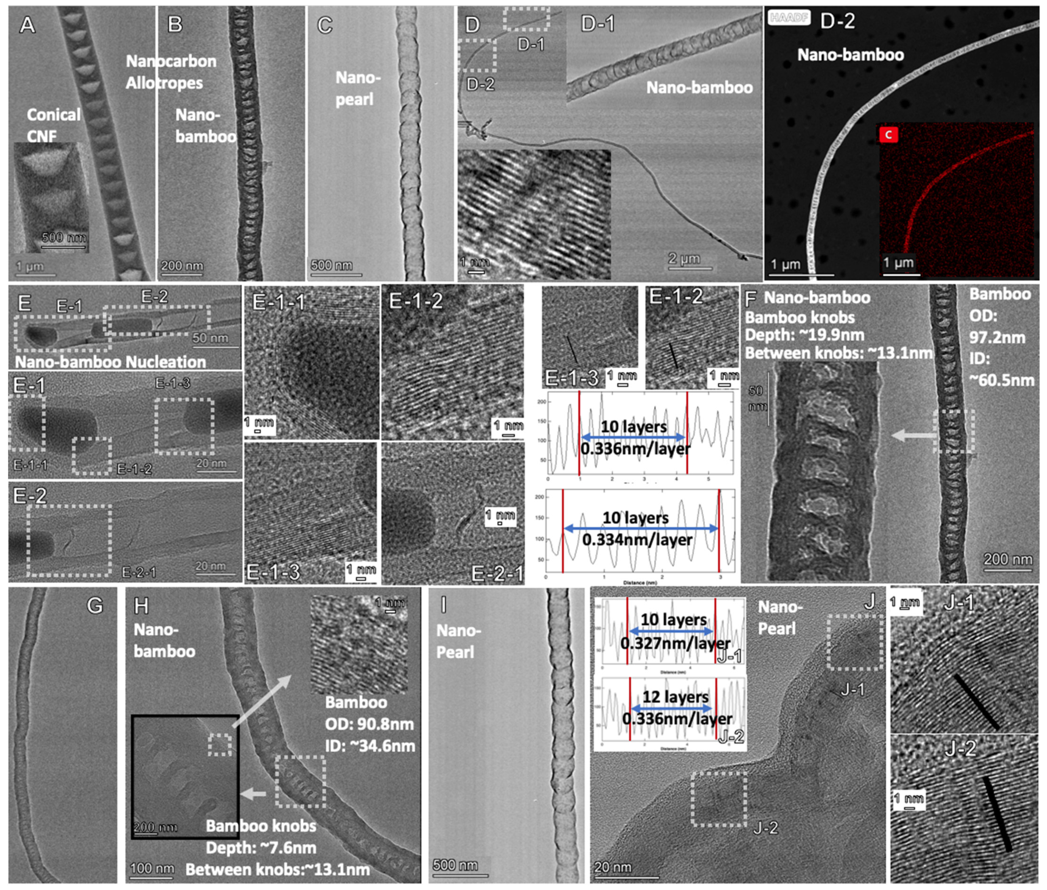
Figure 3 compares TEM of the new nano-bamboo, nano-pearl and conical CNF nanocarbon allotropes synthesized by molten carbonate electrolysis. As seen in the top left panel of the figure, the conical carbon nanofibers (CNFs) exhibit conical voids typical of this CNF structure. Growth of the nano-bamboo is seen in the left middle of the figure and is nucleation driven, and the nucleation region appears to change shape, moving from tip to interior of the structure. We hypothesize that the lateral walls forming the bamboo “knobs” may be related to a periodic depletion of the carbon building leading walls. The walls of the nano-bamboo and nano-pearl allotropes exhibit graphene walls characterized by the typical intergraphene wall separation of 0.33 to 0.34 nm, as noted, and as measured by the observed separation between dense carbon planes in the TEM. The lower left of the figure shows the lateral multiple graphene layers separating the “knobs” of the nano-bamboo structure. The lower right of the figure shows the curved multiple graphene layers comprising the walls of the individual “beads” of the nano-pearl structure.
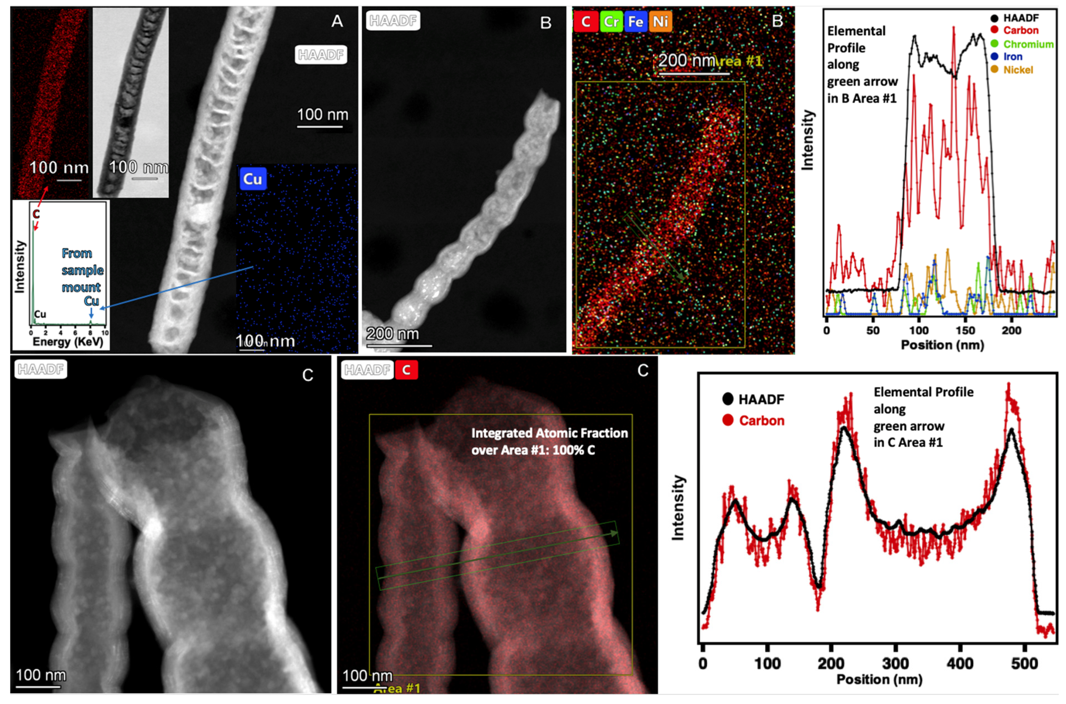
Figure 4 probes the elemental composition by HAADF (High Angle Annular Dark-Field TEM) and compares TEM of the new nano-bamboo and nano-pearl nanocarbon allotropes synthesized by molten carbonate electrolysis. As seen from the HAADF, the nano-bamboo product is pure carbon. That is with the exception of the presence of copper that, as shown in the lower left corner of the top left panel, is pervasively distributed at low concentration throughout, and likely originates from the grid mount of the product sample. HAADF probes two nano-pearl samples. The first exhibits a high or 100% concentration of carbon (the noise level is high) and little or no Ni, Cr or Fe. The second probes for carbon at higher resolutions and the rise and fall of carbon levels is evident as the probe moves from left to right over two separate nano-pearl structures.
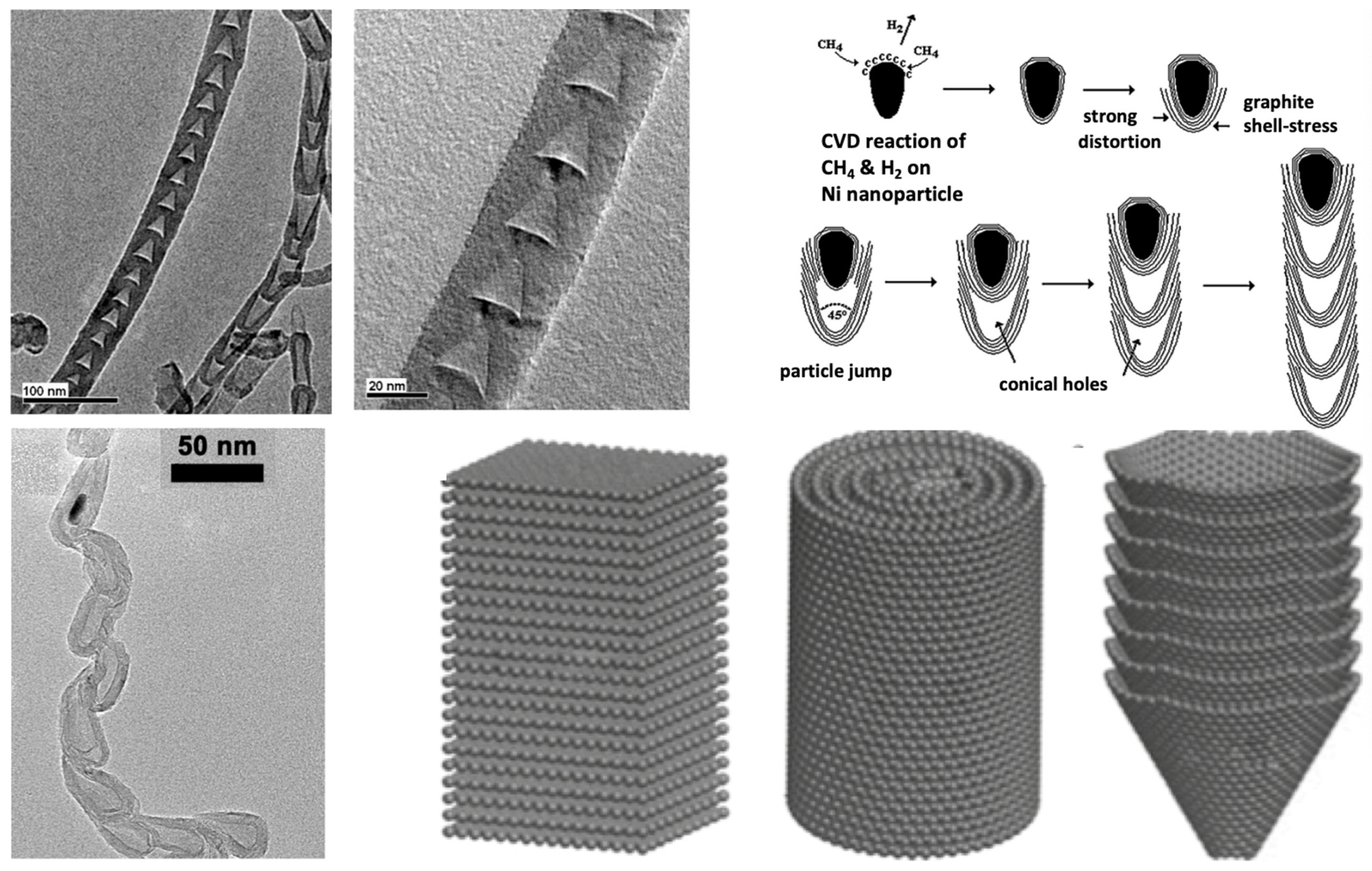
The conical CNF, nano-bamboo and nano-pearl are new and unusual high-yield carbon allotropes as synthesized by molten electrolysis. Similar CVD synthesized morphologies have been synthesized by CVD. In particular, the CVD conical CNF structure has been widely characterized as shown in the upper row of Figure 5 [53,54,55,56]. In that figure, it is proposed that the morphology in CVD is due to repeated stress-induced deformation of the shape of the nucleating (Ni) metal, which causes the metal particles to jump and form the observed lateral graphene separation bridging the allotrope walls. Globular spaced nano-bamboo and nano-pearl allotropes are less common in CVD but have been observed. An example is shown in the lower left row of Figure 5, whose structures were attributed to the periodic formation of pores in the structure due to defects on the outer layers [57,58,59]. One specific application of bamboo CVD CNTs is as platforms for building layer by layer based biosensors [60]. Generally, carbon fibers are categorized as amorphous, or as shown on the lower right side of Figure 5, as built from graphene platelets, carbon nanotubes or conical type structures [61,62].
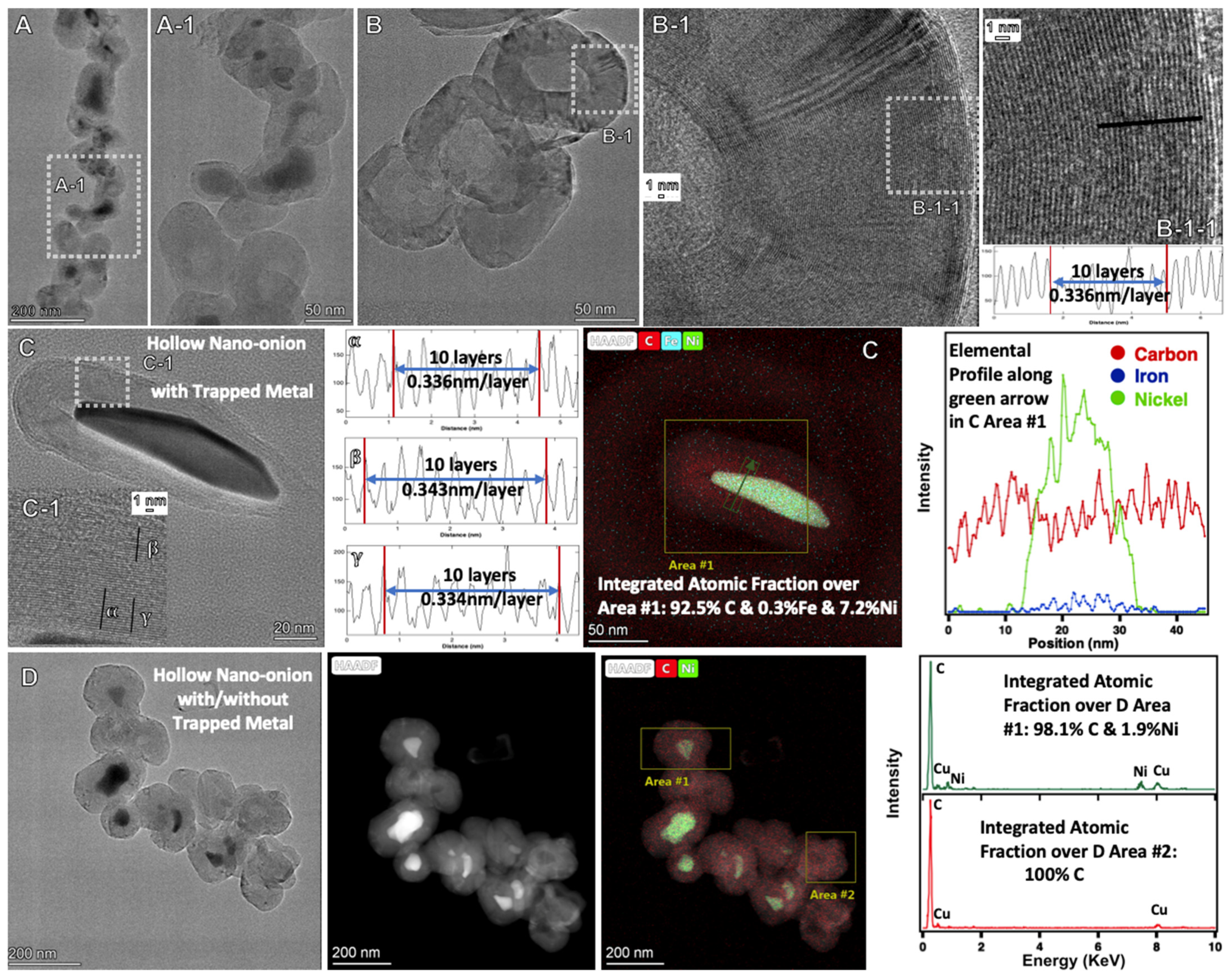
Figure 6 probes the TEM and the elemental composition by HAADF of the new hollow nano-onion nanocarbon allotropes synthesized by molten carbonate electrolysis. As seen, some of the nano-onion inner cores contain metal while others are void. The walls of the hollow nano-onions are composed of graphene layers as characterized by the typical intergraphene wall separation of 0.33 to 0.34 nm, as noted in Figure 6 and as measured by the observed separation between dense TEM carbon planes. As seen in the HAADF of the figure, when the core is vacant, the nano-onion is pure carbon, and when the core contains metal, the metal is either nickel or a mix of nickel and iron.
2.3. Electrochemical Conditions to Synthesize Nickel-Coated CNTs, and Onion and Flower Nanocarbon Allotropes from CO2
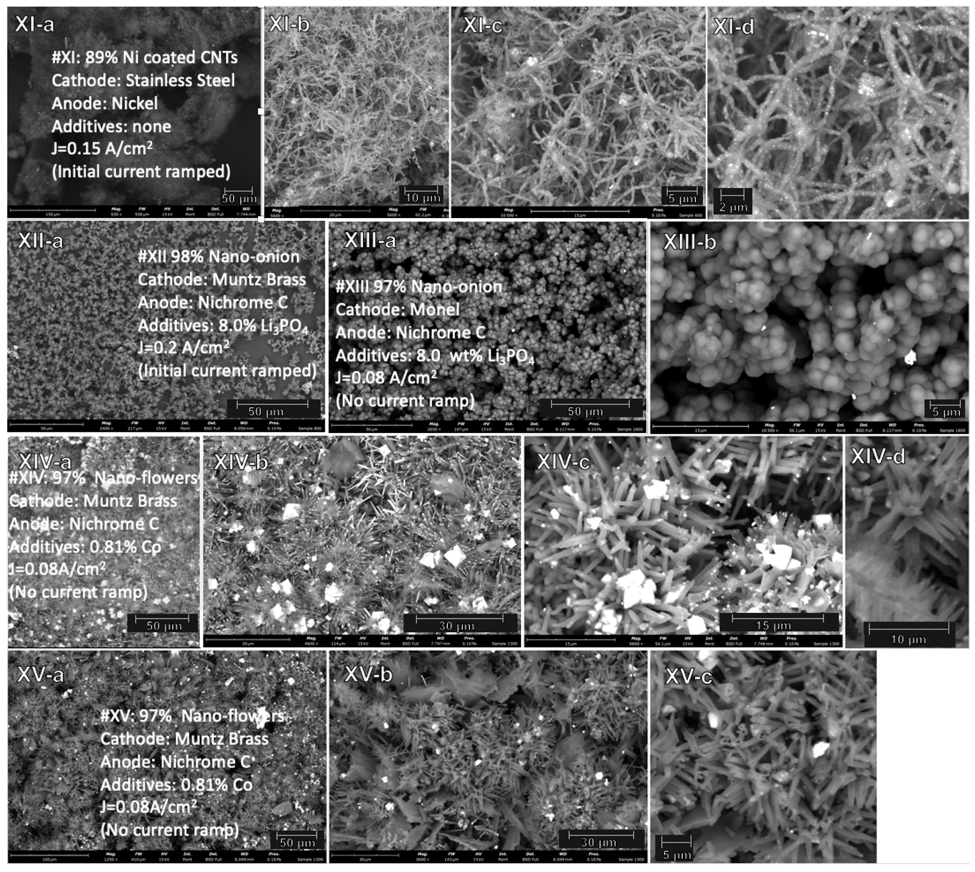
A nickel anode or an excess of added nickel leads to nickel-coated CNT. Rather than forming alternative allotropes, such as nano-bamboo or nano-pearl, the use of excess nickel, particularly (i) when employed with a stainless steel cathode, (ii) when utilized at higher electrolysis current densities, and (iii) with the activation by an initial current ramp, tends to coat the carbon nanotube with nickel. This is summarized in the top row of Table 3 as Electrolysis X, in which 0.81 wt% Ni powder is added to the Li2CO3 electrolyte, and Nichrome C is used as the anode. The electrolysis is conducted at 0.20 A/cm2 and exhibits a coulombic efficiency of 98.9%. The Ni coating is further improved (appearing more uniform in the SEM) in Electrolysis XI in Table 3 and as the top row in Figure 7, when a pure nickel, rather than Nichrome C, anode is used, but no Ni powder is added to the electrolytes, and there is no current ramp employed. The electrolysis is conducted at 0.15 A/cm2 and exhibits a coulombic efficiency of 93.4%.
The exclusion of transition metals from the molten electrolysis environment prevents their activity as nucleation points for carbon growth and suppresses the growth of carbon nanotubes. Suppression of the metal nucleated growth of CNTs, such as through use of a noble metal anode, was found to be an effective means to promote the growth of another nanocarbon: carbon nano-onions [25]. Here, another molten electrolysis pathway is found to ensure a high nano-onion product yield, that is through addition of lithium phosphate to the electrolyte. As summarized in Electrolyses XII and XIII in Table 3, with the addition of 8 wt% Li3PO4 to the Li2CO3 electrolyte, the product is nearly pure (97–98%) carbon nano-onions as summarized in Table 3. This nano-onion product is the observed to be the case for a wide range of electrolysynthesis current densities (0.08 to 0.20 A/cm2), with either Muntz Brass or Monel as the cathode, and with (Electrolysis XII) or without (Electrolysis XIII) inclusion of an initial current ramp step during the electrolysis. In a future study, it will be interesting to probe whether phosphates bind or suppress specific free metal availability in molten carbonates in a manner comparable to their tendency to chelate certain metals under ambient aqueous conditions.
A variation of the low current density, Muntz brass cathode, Nichrome C anode, utilizing an aged electrolyte leads to a fascinating new high-purity molten electrolysis nanocarbon allotrope: nano-flowers. Specifically, after the 24 h aging of the electrolyte, an excess (0.081 wt%) of chromium metal powder is added to the electrolyte. The electrolysis is conducted at 0.08 A/cm2 and exhibits a coulombic efficiency of 78%. The electrolyses are repeated (as Electrolyses XIV and XV) and yield the same results as summarized in Table 3 and shown by SEM in Figure 7. As seen in the lower right panel of Figure 7, the product does appear as hollow tubes within the flower morphology. However, the product morphology is highly unusual in several aspects. Collections of tubes seem to burst from a single point, giving the flower-like arrangement. This will require further study and could represent base, rather than tip, growth and multiple growth patterns activated from singular activation points. An alternative mechanism to be explored is tip based, in which the metal nucleation tip is sintered (decreasing in size) as growth progresses, which with continued growth would decrease the diameter of the nanocarbon product. The tubes appear as short, very straight spikes. The spikes have a diameter which diminishes towards the end of the spike. A small percentage of platelets and garnet-like material is interspersed throughout the floral arrangement. Although new as a majority molten electrolytic synthesis product, nano-flowers have been observed not only from carbon, but also from gold, platinum, and silver as well as from zinc and titanium oxides, and have been described as “a newly developed class of nanoparticles showing structure similar to flower” [62,63,64,65]. Chromium may drive both of the proposed mechanisms for nano-flower growth by making nano-metal nucleation points less fluid or bound to the electrode, promoting base growth, or, when it grows from the tip, the chromium does not keep pace with the growing CNM, causing the particle to decrease in size.
2.4. Electrochemical Conditions to Synthesize Nanocarbon Dragon, Tree, Belt and Rod Allotropes from CO2
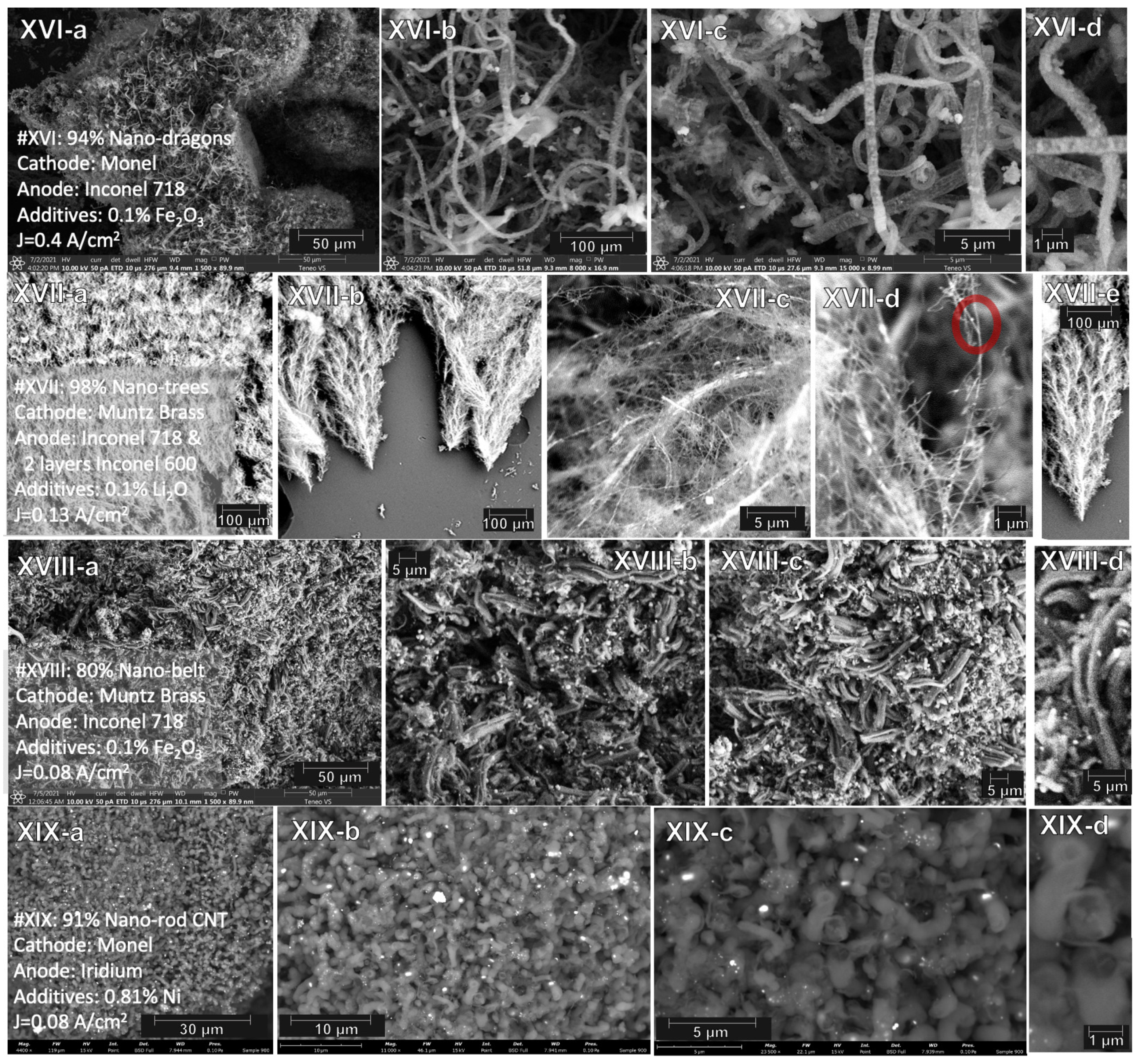
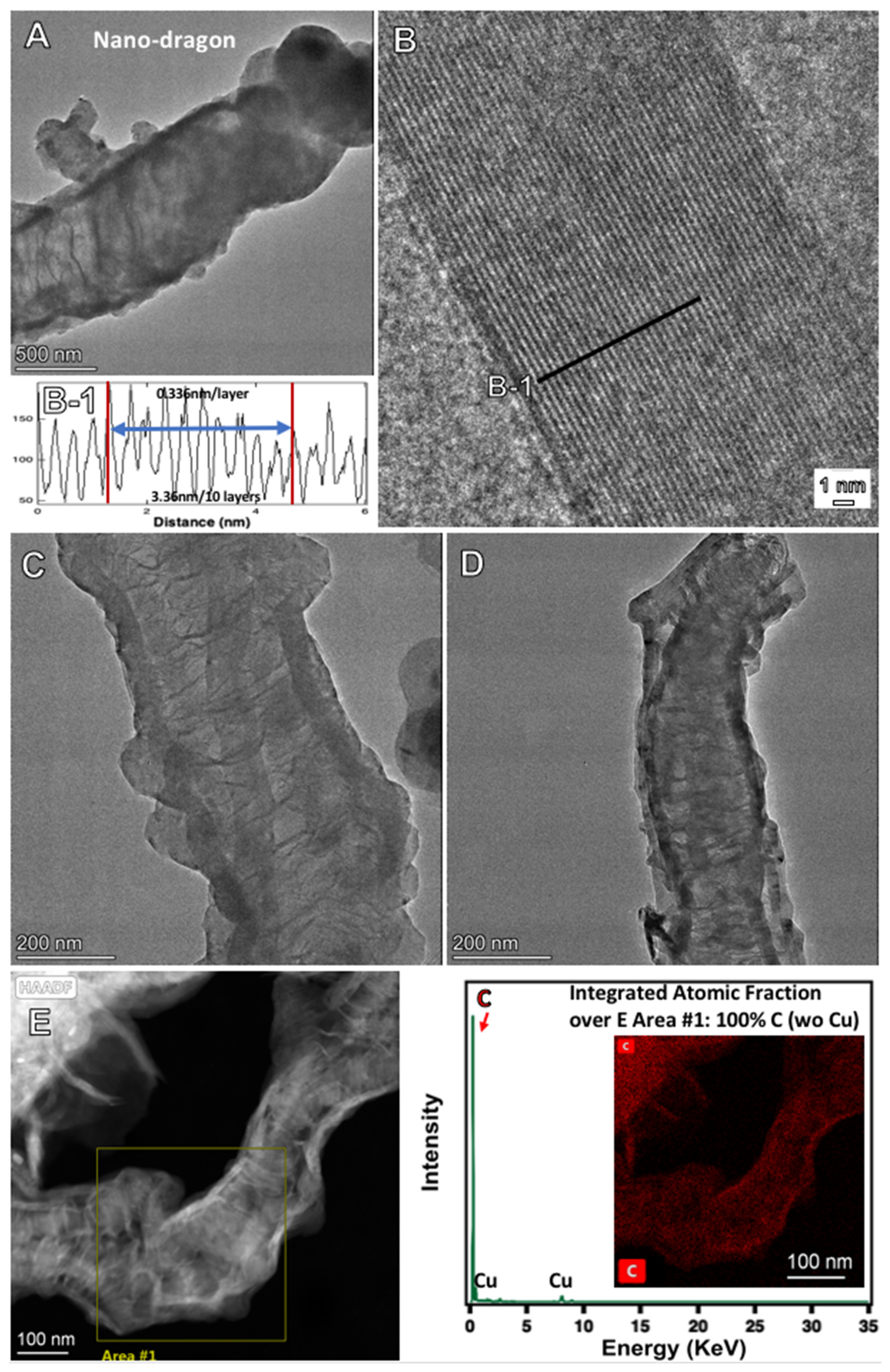
Variation of the electrochemical conditions of CNT product formation to those of Electrolysis XVI leads to a change in allotrope from carbon nanotubes to another fascinating morphology referred to here as nano-dragons and presented in Table 3 and Figure 8. The changes from the earlier syntheses that produced CNTs under similar circumstances, include an Inconel 718 anode, rather than Nichrome C, a higher current density of 0.4, rather than 0.1, A/cm2, (exhibiting a 100% coulombic efficiency), and that the electrolyte is not aged. Unlike the other unique electrolytically synthesized nanocarbon morphologies, carbon nano-dragons do not consist of a a simple, repeated geometric shape, but rather a complex combination of cylinders, platelets and spheres. The small “legs” observed in the Figure 8 SEM images could be smaller branched CNTs or small metal nodules of metal growth.
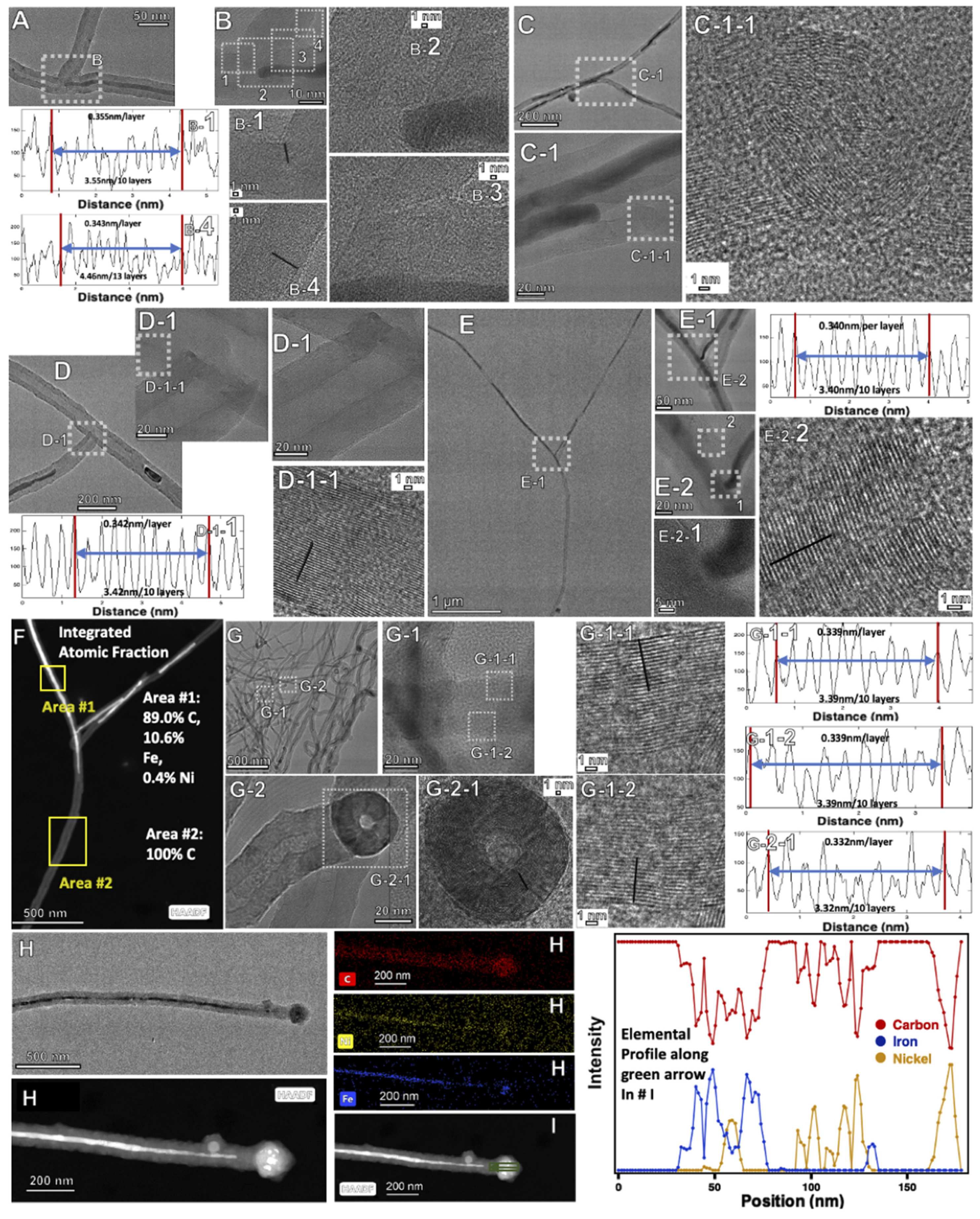
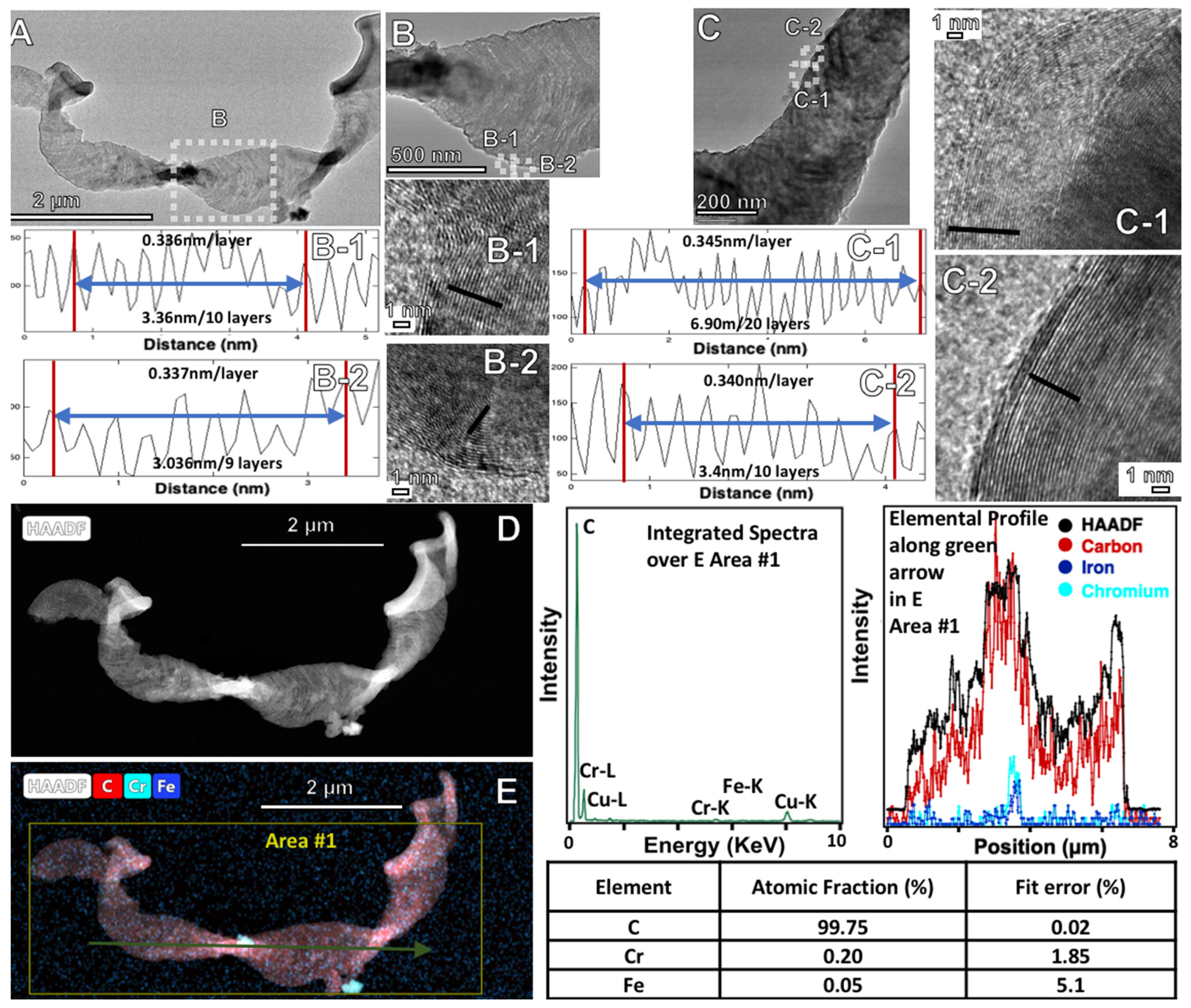
The addition of low levels of lithium oxide has led to high quality of CNTs [21]. With use of a specific anode (Inconel 718 with two layers of Inconel 600), the quality of the product is retained, but the morphology of the CNT changes substantially. We have previously observed larger transition metal nodule growth from the CNTs [18]. With the addition of Li2O, branched carbon nano-trees are included as Electrolysis XVII in Table 3 and Figure 8. The electrolysis is conducted at 0.13 A/cm2 and exhibits a coulombic efficiency of 98.7%. The nano-trees exhibit distinct growth of smaller CNT branches emanating from larger CNT trunks. The red circled area on the right panel of Electrolysis XVII in Figure 8 shows an example of y section branching. Addition of low levels of iron oxide leads to high quality CNTs. However, with 24 h aging of the electrolyte followed by subsequent addition, as in Electrolysis XVIII in Table 3 and Figure 8, an alternative flattened nanocarbon morphology is observed, which is referred to here as nano-belts. The electrolysis is conducted at 0.08 A/cm2 and exhibits a coulombic efficiency of 79%. The nano-belt structure appears to consist of a flattened (or “deflated”) carbon nanotube.
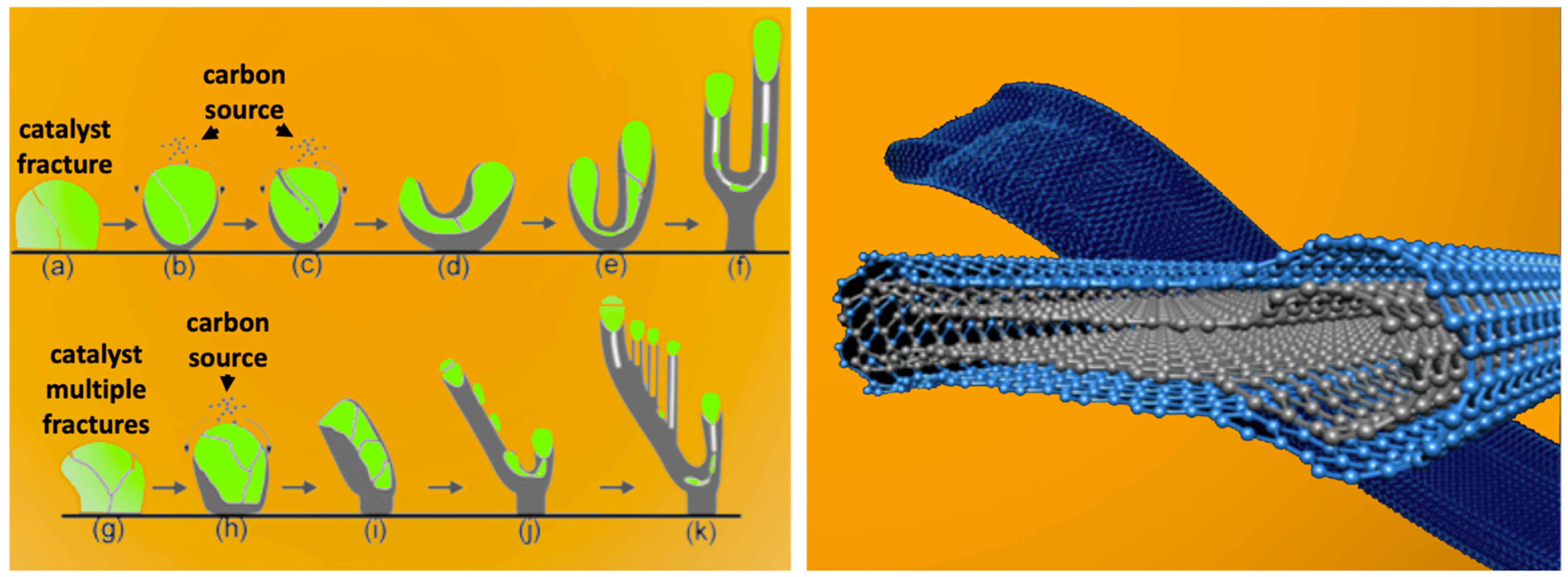
TEM and HAADF elemental analysis of the nano-dragon, nanobelt and nanotree structures are presented in Figure 9, Figure 10, Figure 11, Figure 12 and Figure 13. In Figure 9, the nano-dragon structure is seen as a graphitic structure, albeit complex. A similar looking Pt, rather than C, structure has been previously observed and described as a bumpy surface on one-dimensional Pt nanowires [66]. The nano-tree allotrope is seen in Figure 10 to consist of CNTs, but differs from the conventional CNT structures, which generally do not contain merged CNTs. However, the nano-tree morphology includes intersecting CNTs as seen in Figure 10, whose structures merge and appear to branch off one another. A nanocarbon CVD growth branching mechanism has been suggested and is shown in Figure 11, catalyzed by fractionation of the nucleation sites leading to carbon branches [67]. In Figure 10 and Figure 12, it can be seen that the interior of nano-trees and nano-belts can respectively contain nickel and iron, or nickel in the structure interior. As seen in Figure 12, the nano-belt product is flat and consists of graphene layers, but other than the measured presence of nickel, the mechanism of this unusual flat morphology is evident from the TEM. CVD nano-belt CNT structures have been previously synthesized with a schematic structure illustrated on the right side of Figure 11 [68].
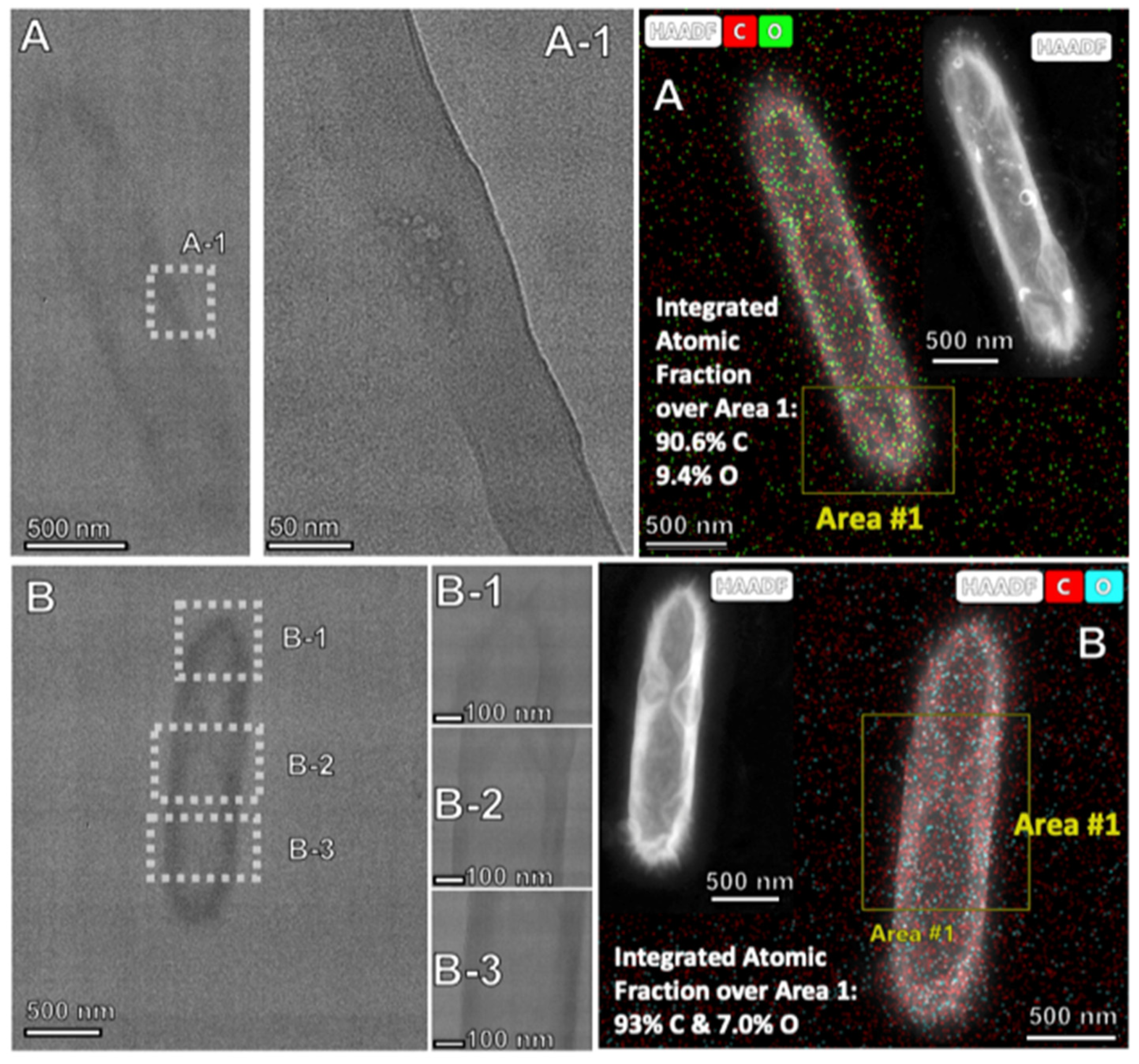
Without aging the electrolyte, the low current density (0.08 A/cm2, exhibiting a coulombic efficiency of 80%), long-term growth (18 h) growth of carbon nanotubes with a Monel cathode, iridium anode, 0.81% Ni, and no ramped current activation step, leads to squat, ring-like nano-rod allotropes seen in Figure 13, and included in Table 4, as Electrolysis XIX. Of the electrolyses presented here, the product is singularly unusual from two physical chemical perspectives: (1) The TEM in Figure 13 reveals no evidence of a layered graphene structure. However, as shown in a later section, this morphology does exhibit an XRD peak and Raman spectrum typical of graphitic layered graphene structures. (2) As seen in the elemental analysis in Figure 13, the nano-rods are the only one of the new molten synthesized nanocarbon allotropes in which a significant concentration of oxygen (7.0 to 9.4%) is observed. With the bulbous rod-like morphology, rather than a growth which increases a CNT’s length along with its diameter in time, this appears consistent with a long-term growth dominated by diameter, rather than length, increases.
2.5. The Diverse Range of Carbon Allotropes Formed by Molten Electrolysis
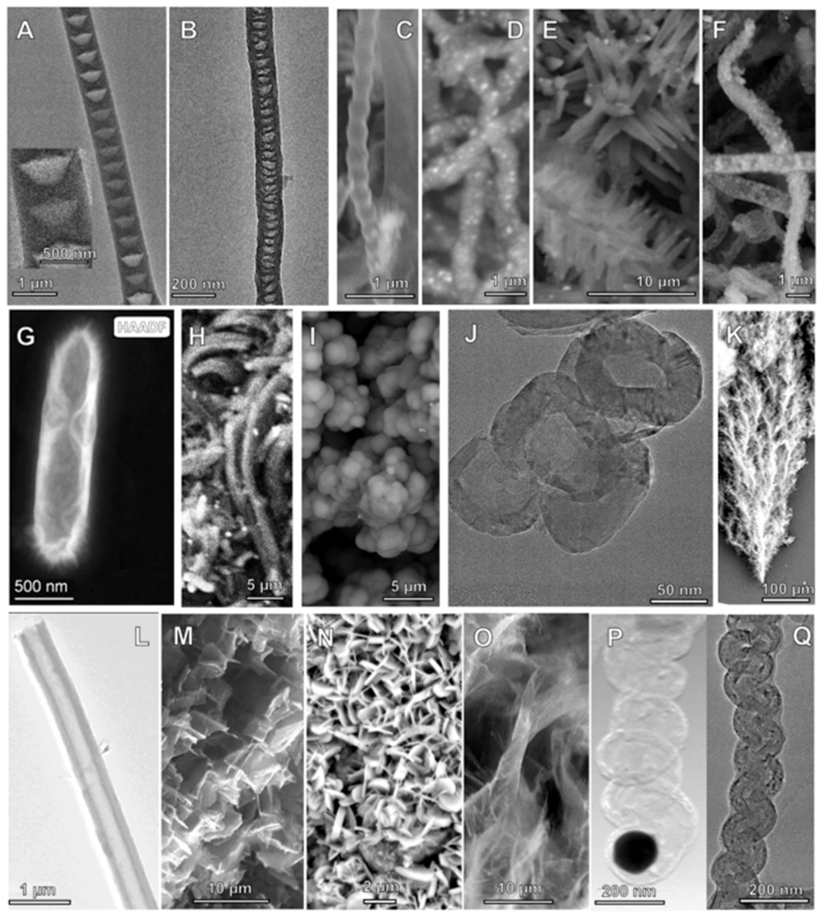
The top row and middle row of Figure 14 compares microscopy of this study’s new carbon allotropes to those structures in the second row that were previously formed by molten electrolysis. The new electrolysis synthesis structures shown are conical CNF, nano-bamboo, nano-pearl, Ni coated CNT, nano-flower, nano-dragon, nano-rod, nano belt, nano-onion (also previously synthesized by alternative methodology in [25]), hollow nano-onion, and nano-tree. The previous distinct nanocarbon structures synthesized were carbon nanotubes ([11], and onward), nano-platelet [28], graphene (a two-step synthesis of CO2 molten electrolysis followed by exfoliation) [27] and nano-helices [20].
Annual anthropogenic emissions of carbon amount to about 7 Gigatons. Can molten carbon splitting of CO2 occur at a sufficient level to mitigate this anthropogenic carbon and mitigate global warming? Yes, but at a massive scale, as previously described [69].
Rather, than building stockpiles of CNMs to mitigate climate change, we put forth that the collective physical chemical properties of graphitic nanocarbon allotropes (including highest strength, high thermal and electrical conductivities, electronic and electrical storage properties, lubrication, medical applications, durable textiles, etc., and properties yet to be discovered) are greatly preferred over conventional materials and provide an incentive for their replacement by CNMs. Coupled with the very low cost of inorganic molten electrolysis (a low cost analogous to the industrial cost of aluminum production by splitting of aluminum oxide, but instead nanocarbon production by splitting of carbon dioxide), these new CNMs provide a value-added logical choice for replacement of these conventional materials, while eliminating CO2. Collectively, replacement of today’s annual 9 Gigaton (Gt) usage of these conventional materials (including, annually, production of cement = 4 Gt, steel = 1.6 Gt, aluminum = 0.058 Gt, plastics = 0.37 Gt, wood construction = 2.0 Gt, cotton and wool = 0.1 Gt, paper and cardboard = 0.4 Gt) provides the opportunity to eliminate net anthropogenic CO2 and mitigate climate change.
2.6. Raman and XRD of the New Structures Formed by Molten Electrolysis
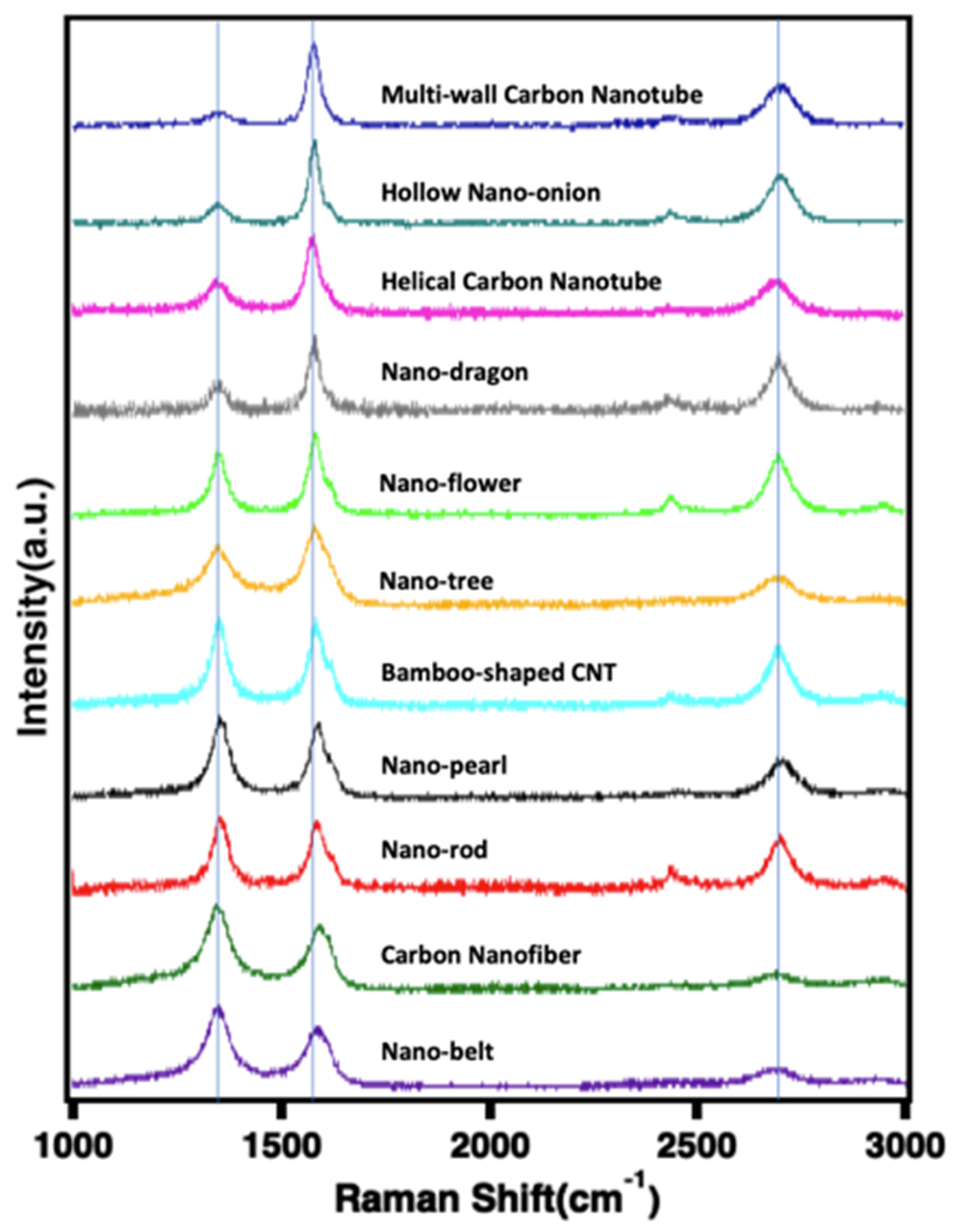
Figure 15 presents the effect of variation of the electrolysis conditions on the Raman spectra and XRD of the new carbon products of CO2 electrolysis in 770 °C Li2CO3. For comparison purposes, also included are the Raman spectra of the CNTs [29,38]. The graphitic fingerprints lie in the 1880–2300 cm−1 and are related to different collective vibrations of sp-hybridized C-C bonds. The tangential G-band (at ~1580 cm−1) is derived from the graphite-like in-plane mode of E2G symmetry, and can be split into several modes, two of which are most distinct: the G1 (1577 cm−1) and G2 (1610 cm−1). The Raman spectrum exhibits two sharp peaks ~1350 and ~1580 cm−1, which correspond to the disorder-induced mode (D band) and the high frequency E2G first order mode (G band), respectively, and an additional peak, the 2D band, at 2700 cm−1. The G’ peak at ~2300, is related to the collective stretching vibrations of sp-hybridized C–C bonds.
The intensity ratio between D band and G band (ID/IG) is a useful parameter to evaluate the relative number of defects and degree of graphitization. Table 4 summarizes Raman band peak locations and includes calculated (ID/IG) and (I2D/IG) peak ratios for the various carbon allotropes. A higher ratio ID/IG or a shift in IG frequency15 is a measure of increased defects in the carbon graphitic structure [70]. Defects that can occur in the graphitic structure include replacement of carbon sp2 bonds, typical of the hexagonal carbon configuration in the graphene layers comprising the structures, with sp3, increase in pores or missing carbon in the graphene, and enhancement of defects that cause formation of heptagonal and pentagonal, rather than the conventional hexagonal, graphene building blocks of graphene [71].
Typically, ID/IG for multi-walled carbon nanotubes is in the range of 0.2 to 06. Compared to these values, with the exception of the hollow nano-onions, the new carbon allotropes generally exhibit a higher than 0.6 ID/IG, evidence of a higher number of defects and perhaps consistent with the greater morphological complexity of these new allotropes. The nanocarbon bamboo, pearl, annular and belts each exhibit a relatively high level of defect, often associated with greater pores and twists and turns in the structure due to the higher presence of sp3 carbons. As observed from Table 4, the order of the increasing ID/IG ratio is
CNT < hollow nano-onion < dragon < flower < trees < bamboo < pearl < rod < CNF < belt.
The shift to higher frequencies of the frequency, ν, of the G band generally correlates with the observed ID/IG variation, with variations due to near lying ratios, and with the exception of an unusually large shift for nano-bamboo.
High levels of Ni, Cr or Co added to the electrolyte (nano-bamboo, nano-pearl and nano-flower allotropes) also appear to correlate with an increase in defects, and the very high added Ni powder used in the nano-rod synthesis correlates with a very high level of defects as indicated by the shift in IG frequency and an increase in ID/IG. Previously, increased concentrations of iron oxide added to the Li2CO3 electrolyte correlated with an increasing degree of disorder in the graphitic structure [20,21]. Interestingly, it is the synthesis with a low level of added iron oxide powder (but only added prior to the 24 h aging of the electrolyte) that results in the CNMs with the highest level of defects, the nano-belt CNM.
Lower defects are associated with applications which require high electrical conductivity and strength, while high defects are associated with applications which permit high diffusivity through the structure, such as those associated with increased intercalation and higher anodic capacity in Li-ion batteries and higher charge super capacitor.
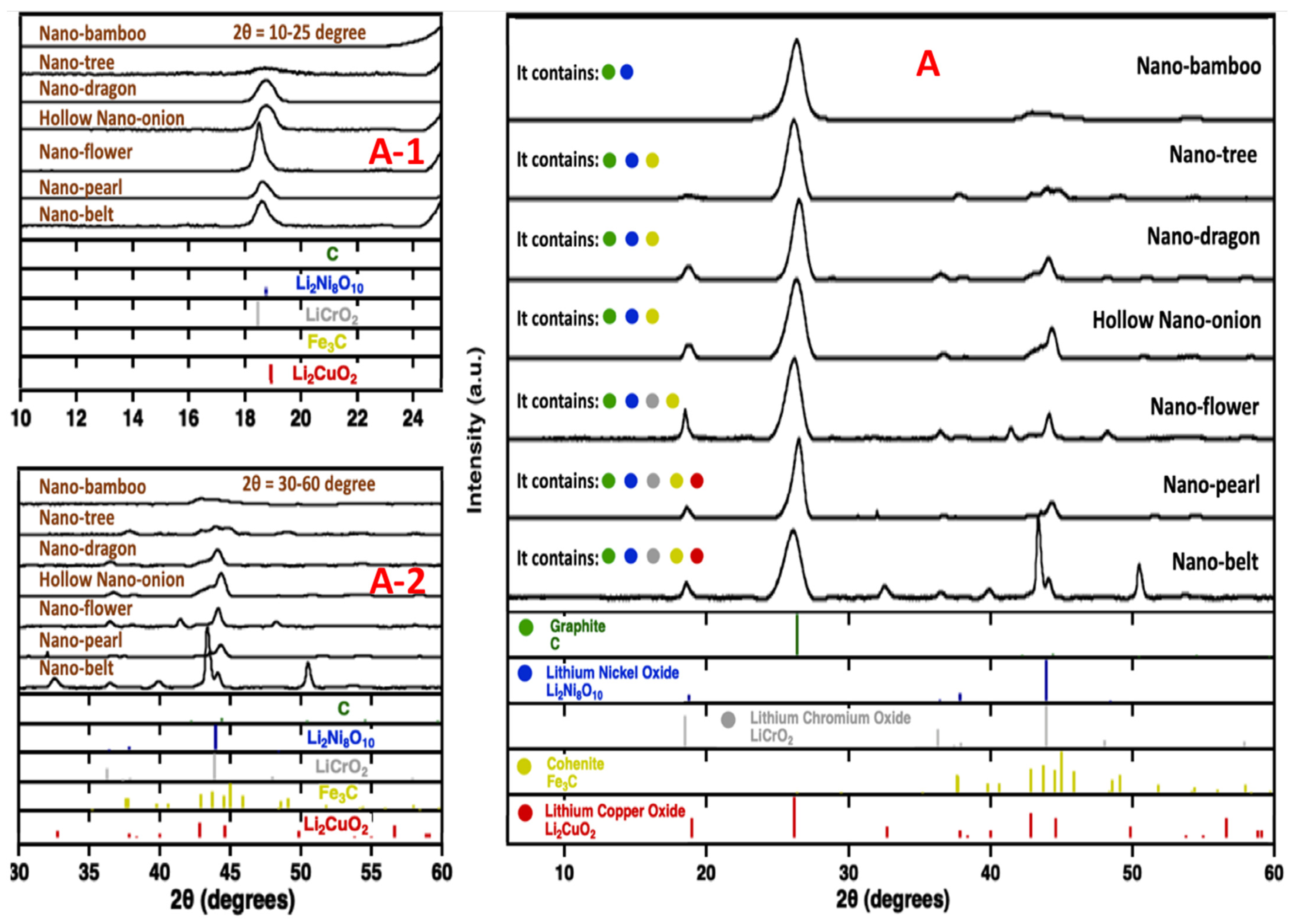
Along with the XRD library of relevant compound spectra, XRD is presented in Figure 16 of the new nanocarbon morphologies products, prepared as summarized in Table 2 and Table 3, and with SEM in Figure 2, Figure 7 and Figure 8. Each of the spectra exhibit the strong, sharp diffraction peak at 2θ = 27° characteristic of graphitic structures, and no indication of the broad peak indicative of amorphous carbon. In addition to graphite, the products XRD are grouped by which metal salts are present. Nano-bamboo exhibits the simplest composition with only a lithiated nickel salt present. The next most complex compositions, seen in the middle of Figure 16, are nano-dragons, nano-flowers and nano-trees, which also include the iron carbide salt Fe3C. The next most complex composition is exhibited in the figure in the lower left hand corner, for hollow nano-onions, which exhibit each of those previous metal salts as well as a lithiated chromium(III) salt. Finally, both nano-belt and nano-pearls include an additional lithiated copper salt, and it may be noted that they were respectively synthesized with a Muntz brass and a Monel cathode which contain copper. However, the source of the copper requires further investigation. To enter the nanocarbon, the copper may need to dissolve from the cathode, which is under cathodic bias. This did not occur with the other CNM products. The nano-belt XRD spectra is distinct from the others having a dominant peak at 2θ = 43°, reflecting a higher concentration of metals than in the other products. The diminished presence of defects previously noted by the Raman spectra for the hollow nano-onion morphology, along with the XRD presence of Li2Ni8O10, LiCrO2 and Fe3C provide evidence that the co-presence of Ni, Cr and Fe as nucleating agents can diminish defects in the structure compared to Ni. On the other hand, the enhanced presence of defects previously noted by the Raman spectra for the nano-belt and nano-pearl morphologies, along with the XRD presence of LiCuO2, provide evidence that the copper salt increases defects in the structure compared to Ni, Fe or Cr as transition meal nucleating agents. Finally, it should be noted that the singular (amongst all the electrolyses) addition of cobalt powder to Electrolyses XIV and XV must be correlated with the subsequent observed formation of the nano-flower allotrope. However, this cobalt does not make its way into the product as analyzed by XRD in Figure 16, is observed only in trace quantities by HAADF TEM (to be delineated and probed in future studies) and presumably has another role in promoting formation of this unusual products.
3. Materials and Methods
3.1. Materials
Lithium carbonate (Li2CO3, 99.5%), lithium oxide (Li2O, 99.5%), lithium phosphate Li3PO4 (Li3PO4, 99.5%), iron oxide (Fe2O3, 99.9%, Alfa Aesar) and boric acid (H3BO3, Alfa Aesar 99 + %) were used as electrolyte components in this study. For electrodes, Nichrome A (0.04-inch-thick), Nichrome C (0.04-inch-thick), Inconel 600 (0.25-inch-thick), Inconel 625 (0.25-inch-thick), Monel 400, Stainless Steel 304 (0.25-inch-thick) and Muntz Brass (0.25-inch-thick) were purchased from onlinemetals.com. Ni powder was 3–7 µm (99.9%, Alfa Aesar). Cr powder was <10 µm (99.2%, Alfa Aesar). Co powder was 1.6 µm (99.8%, Alfa Aesar). Iron oxide was 99.9% Fe2O3 (Alfa Aesar). Co powder was 1.6 µm (99.8%, Alfa Aesar). Inconel 600 (100 mesh) was purchased from Cleveland Cloth. The electrolysis was a conducted in a high form crucible >99.6% alumina (Advalue).
3.2. Electrolysis and Purification
Specific electrolyte compositions of each electrolyte are described in the text. The electrolyte was pre-mixed by weight in the noted ratios then metal or metal oxide additives were added if used. The cathode was mounted vertically across from the anode and immersed in the electrolyte. Generally, the electrodes are immersed subsequent to electrolyte melt. For several, as noted, electrolyses, once melted, the electrolyte was maintained at 770 °C (“aging” the electrolyte) prior to immersion of the electrolytes followed by immediate electrolysis. Generally, the electrolysis was driven with a described constant current density. As noted, for some electrolyses, the current density is ramped in several steps building to the applied electrolysis current which is then maintained at a constant current density. Instead, most of the electrolyses are initiated, and held, at a single constant current. The electrolysis temperature was 770 °C.
3.3. Product Characterization
The raw product was collected from the cathode after the experiment and cooldown, followed by an aqueous wash procedure which removes electrolyte congealed with the product as the cathode cools. The washed carbon product was separated by vacuum filtration. The washed carbon product is dried overnight in a 60 °C oven, yielding a black powder product.
The coulombic efficiency of electrolysis is the percent of applied, constant current charge that was converted to carbon determined as:
100% × Cexperimental/Ctheoretica
This is measured by the mass of washed carbon product removed from the cathode, Cexperimental, and calculated from the theoretical mass, Ctheoretical = (Q/nF) × (12.01 g C mol−1) which is determined from Q, the time integrated charged passed during the electrolysis, F, the Faraday (96,485 As mol−1 e−), and the n = 4 e− mol−1 reduction of tetravalent carbon consistent with Equation (2).
Characterization: The carbon product was washed and analyzed by PHENOM Pro Pro-X SEM (with EDX), FEI Teneo LV SEM, and by FEI Teneo Talos F200X TEM (with EDX). XRD powder diffraction analyses were conducted with a Rigaku D = Max 2200 XRD diffractometer and analyzed with the Jade software package. Raman spectra were collected with a LabRAM HR800 Raman microscope (HORIBA). This Raman spectrometer/microscope uses an incident laser light with a high resolution of 0.6 cm−1 at 532.14 nm wavelength. The Raman spectrometer/microscope uses an incident 0.13 mW laser light with a high resolution of 0.6 cm−1 at 532.14 nm wavelength with 1800 gr/mm, 800 mm focal objective, and 100 ms integration. The PHENOM Pro SEM provides over 100,000× electron optical magnification and uses up to a 15 kV acceleration voltage for imaging and analysis. Specifications of the other instruments are available online from the manufacturers.
4. Conclusions
Known conventional carbon allotropes include diamond and graphite, and more recently buckyballs, graphene, carbon nanofibers and CNTs. In this study, the range of carbon allotropes and morphologies, and in particular nanocarbon morphologies, that can be synthesized by the molten carbonate electrolysis of CO2 has been greatly expanded. Fascinating high purity morphologies that have been obtained in this study by the systematic variation of electrolysis conditions are conical CNF, nano-bamboo, nano-pearl, Ni-coated CNT, nano-flower, nano-dragon, nano-rod, nano-belt, nano-onion (also previously synthesized by an alternative methodology in [25]), hollow nano-onions and nano-trees. Each of these CNMs have their unusual and distinctive morphologies, such as the nano-trees with their branching CNT structure, or the nano-bamboo and -pearl with their different, but repeated knob or bulb shapes. These distinctive morphologies may lead to unusual physical chemical properties with implications useful to applications, such as those utilizing the high strength, high thermal, magnetic, electronic, piezoelectronic, tribological characteristics of graphene-based materials, but which distribute these properties differently throughout the unusual geometries of this novel allotropes. For example, alternative applications such as high-capacity Li-anodes, unusual electronics, EMF shielding, improved lubricants, and new structural or polymer composites may be anticipated.
This study has explored a variety of electrochemical configurations, systematically varying electrode composition, current density and electrolysis time, current ramping initiation, and variation of electrolyte additives and their concentrations. The observed nanocarbon structures were analyzed by SEM, TEM, including with HAADF, Raman and XRD. With the exception of the nano-rod structure, each of the structures is graphitic in nature, containing graphene layers arranged in a variety of geometries. The graphene layers exhibit the characteristic inter-layer spacing of 0.33 to 0.34 nm. Except for the presence of Ni, Fe, Cr and occasionally Cu, which may serve as nucleating growth sites, each of the structures is pure carbon. Generally, intersecting graphene layers did not merge, but in the nano-tree, the graphene layers bend at intersections leading to the observed branching.
Many of the structures including nano-bamboo, nano-pearl, Ni-coated CNTs and conical CNFs exhibit walls containing concentric graphene layers. The nano-dragon and nano-belt structures include layered planer or planar-twisted graphene layers. Several of the observed structures, including nano-trees, and hollow and filled nano-onions, exhibit concentric, highly spherical graphene layers generally composed of carbon and containing a low level of internal transition metal. A new pathway to the formation of nano-onions via phosphate addition to the electrolyte is demonstrated, and the hypothesis that phosphate selectively binds transition metal ions should be pursued.
Each of the syntheses were conducted in a 770 °C Li2CO3 electrolyte with or without various additives, on a variety of metal or metal alloy electrodes, and with a range of current densities. In a sister paper [29], slight variations of these same synthesis parameters form high-purity carbon but only with the CNT structure. The varied anode and cathodes contained either pure Ni, or mixes also including Fe and Cr, or various mixes of an extended variety of transition metals. However, the changing conditions led to variations of the CNT morphology (length, diameter, curled or straight, added defects etc.). All syntheses in the study from Electrolysis IV onward produced a high-purity product of the stated structure, with the exception of the conical CNFs that were a minority (6%) within a majority of nano-bamboo carbon, and the moderate purity (85%) nano-belt carbon product. Coulombic efficiency of the electrolyses ranged from 79 to 80% at lower current densities of 0.08 A/cm2, to over 99% at current densities of 0.2 A/cm2 or higher. The high purity products each exhibited sharp XRD graphic peaks, and a moderate (0.3 to 1.3) Raman ID/IG ratio indicative of a moderate level of defects in the structure. In addition to a majority of pure, graphitic carbon, the XRD also exhibited different singular or mixed transition metal salts of either iron carbide, or nickel, chromium or copper lithiated oxides.
TEM HAADF of the new nanostructures shows that their inner core is generally metal-free (void, with the walls 100% carbon), but in other areas, the void is filled with transition metals: Ni, Fe and/or Cr. Except for the nano-rod product, each of the structures included distinct graphene layers with a graphene characteristic, inter-layer spacing of 0.33–0.34 nm. Depending on the nanostructure, adjacent graphene layers were organized either in a planer, cylindrical or spherical geometry. When the internal transition metal is in the tip, the layered graphene walls are observed to bend in a highly spherical fashion around the metal supporting the transition metal nucleated CNT growth mechanism. The use of a Ni-anode, or an excess of added Ni to the electrolyte, leads to Ni-coated CNTs when stainless steel is used as the cathode. Generally, intersecting graphene layers did not merge, but in the nano-tree allotrope, graphene layers bend to become part of a CNT intersection consistent with branching.
Molten carbonate electrolysis of CO2 provides an effective path for the synthesis of a portfolio of unusual, valuable nanocarbon allotropes. Mass production of these structures from CO2 will provide a valuable incentive to consume this greenhouse gas. Such structures are rare, or were previously non-existent, and are not generally commercially available. However, those that are in use, such as nano-onions made by pyrolysis of nano-diamonds [35], or by CVD, have high carbon footprints and associated costs at over USD 1 million/ton. CNT production by the molten carbonate electrolysis of CO2, the C2CNT process, is an inexpensive synthesis comparable to the cost of aluminum oxide splitting in the industrial production of aluminum [14]. The scale-up of this process was awarded the 2021 Carbon XPrize XFactor award for producing the most valuable product from CO2 [31,32]. The new synthesis conditions consist of small variations of the scaled C2CNT process with a comparable, straightforward path to scale up to contribute to consumption of CO2 for climate change mitigation.
Author Contributions
Conceptualization, S.L. and G.L.; methodology, S.L., X.L., G.L. and X.W.; writing S.L. and G.L. All authors have read and agreed to the published version of the manuscript.
Funding
C2CNT LLC funded this research through the C2CNT LLC XPrize support funding.
Data Availability Statement
The authors confirm that the data supporting the findings of this study are available within the article.
Conflicts of Interest
The authors declare no conflict of interest.
References
- CO2-Earth: Daily CO2 Values. Available online: https://www.CO2.earth/daily-CO2 (accessed on 7 December 2021).
- NASA: Global Climate Change: The Relentless Rise of Carbon Dioxide. Available online: https://climate.nasa.gov/climate_resources/24/ (accessed on 7 December 2021).
- Urban, M.C. Accelerating extinction risk from climate change. Science 2015, 348, 571–573. [Google Scholar] [CrossRef]
- Pimm, S.L. Climate disruption and biodiversity. Curr. Biol. 2009, 19, R595–R601. [Google Scholar] [CrossRef]
- Praksh, G.K.; Olah, G.A.; Licht, S.; Jackson, N.B. Reversing Global Warming: Chemical Recycling and Utilization of CO2; Report of 2008 NSF Workshop; University of Southern California: Los Angeles, CA, USA, 2008; Available online: https://loker.usc.edu/ReversingGlobalWarming.pdf (accessed on 7 December 2021).
- Khanna, V.; Bakshi, B.R.; Lee, L.J. Carbon Nanofiber Production: Life cycle energy consumption and environmental impact. J. Ind. Ecol. 2008, 12, 394–410. [Google Scholar] [CrossRef]
- Licht, S.; Wang, B.; Ghosh, S.; Ayub, H.; Jiang, D.; Ganley, J. New solar carbon capture process: STEP carbon capture. J. Phys. Chem. Lett. 2010, 1, 2363–2368. [Google Scholar] [CrossRef]
- Ren, J.; Li, F.; Lau, J.; Gonzalez-Urbina, L.; Licht, S. One-pot synthesis of carbon nanofibers from CO2. Nano Lett. 2010, 15, 6142–6148. [Google Scholar] [CrossRef]
- Ren, J.; Licht, S. Tracking airborne CO2 mitigation and low cost transformation into valuable carbon nanotubes. Sci. Rep. 2016, 6, 27760. [Google Scholar] [CrossRef]
- Ren, J.; Lau, J.; Lefler, M.; Licht, S. The minimum electrolytic energy needed to convert carbon dioxide to carbon by electrolysis in carbonate melts. J. Phys. Chem. C 2015, 119, 23342–23349. [Google Scholar] [CrossRef]
- Licht, S.; Liu, X.; Licht, G.; Wang, X.; Swesi, A.; Chan, Y. Amplified CO2 reduction of greenhouse gas emissions with C2CNT carbon nanotube composites. Mater. Today Sustain. 2019, 6, 100023. [Google Scholar] [CrossRef]
- Dey, G.; Ren, J.; El-Ghazawi, O.; Licht, S. How does an amalgamated Ni cathode affect carbon nanotube growth? RSC Adv. 2016, 122, 400–410. [Google Scholar]
- Ren, J.; Johnson, M.; Singhal, R.; Licht, S. Transformation of the greenhouse gas CO2 by molten electrolysis into a wide controlled selection of carbon nanotubes. J. CO2 Util. 2017, 18, 335–344. [Google Scholar] [CrossRef]
- Johnson, M.; Ren, J.; Lefler, M.; Licht, G.; Vicini, J.; Licht, S. Data on SEM, TEM and Raman spectra of doped, and wool carbon nanotubes made directly from CO2 by molten electrolysis. Data Br. 2017, 14, 592–606. [Google Scholar] [CrossRef]
- Johnson, M.; Ren, J.; Lefler, M.; Licht, G.; Vicini, J.; Liu, X.; Licht, S. Carbon nanotube wools made directly from CO2 by molten electrolysis: Value driven pathways to carbon dioxide greenhouse gas mitigation. Mater. Today Energy 2017, 5, 230–236. [Google Scholar] [CrossRef]
- Wang, X.; Liu, X.; Licht, G.; Wang, B.; Licht, S. Exploration of alkali cation variation on the synthesis of carbon nanotubes by electrolysis of CO2 in molten carbonates. J. CO2 Util. 2019, 18, 303–312. [Google Scholar] [CrossRef]
- Wang, X.; Licht, G.; Licht, S. Green and scalable separation and purification of carbon materials in molten salt by efficient high-temperature press filtration. Sep. Purif. Technol. 2021, 244, 117719. [Google Scholar] [CrossRef]
- Wang, X.; Sharif, F.; Liu, X.; Licht, G.; Lefer, M.; Licht, S. Magnetic carbon nanotubes: Carbide nucleated electrochemical growth of ferromagnetic CNTs. J. CO2 Util. 2020, 40, 101218. [Google Scholar] [CrossRef]
- Wang, X.; Liu, X.; Licht, G.; Licht, S. Calcium metaborate induced thin walled carbon nanotube syntheses from CO2 by molten carbonate electrolysis. Sci. Rep. 2020, 10, 15146. [Google Scholar] [CrossRef]
- Liu, X.; Licht, G.; Licht, S. The green synthesis of exceptional braided, helical carbon nanotubes and nanospiral platelets made directly from CO2. Mat. Today Chem. 2021, 22, 100529. [Google Scholar] [CrossRef]
- Liu, X.; Licht, G.; Licht, S. Data for the green synthesis of exceptional braided, helical carbon nanotubes and nano spiral platelets made directly from CO2. arXiv 2021, arXiv:2110.05398. [Google Scholar]
- Licht, S.; Douglas, A.; Carter, R.; Lefler, M.; Pint, C. Carbon Nanotubes Produced from Ambient Carbon Dioxide for Environmentally Sustainable Lithium-Ion and Sodium-Ion Battery Anodes. ACS Cent. Sci. 2016, 2, 162–168. [Google Scholar] [CrossRef] [PubMed]
- Lau, J.; Dey, G.; Licht, S. Thermodynamic assessment of CO2 to carbon nanofiber transformation for carbon sequestration in a combined cycle gas or a coal power plant. Energy Conser. Manag. 2016, 122, 400–410. [Google Scholar] [CrossRef]
- Licht, S. Co-production of cement and carbon nanotubes with a carbon negative footprint. J. CO2 Util. 2017, 18, 378–389. [Google Scholar] [CrossRef]
- Liu, X.; Ren, J.; Licht, G.; Wang, X.; Licht, S. Carbon nano-onions made directly from CO2 by molten electrolysis for greenhouse gas mitigation. Adv. Sustain. Syst. 2019, 3, 1900056. [Google Scholar] [CrossRef]
- Ren, J.; Yu, A.; Peng, P.; Lefler, M.; Li, F.F.; Licht, S. Recent advances in solar thermal electrochemical process (STEP) for carbon neutral products and high value nanocarbons. Acc. Chem. Res. 2019, 52, 3177–3187. [Google Scholar] [CrossRef]
- Liu, X.; Wang, X.; Licht, G.; Licht, S. Transformation of the greenhouse gas carbon dioxide to graphene. J. CO2 Util. 2020, 36, 288–294. [Google Scholar] [CrossRef]
- Wang, X.; Licht, G.; Liu, X.; Licht, S. One pot facile transformation of CO2 to an unusual 3-D nan-scaffold morphology of carbon. Sci. Rep. 2020, 10, 21518. [Google Scholar] [CrossRef]
- Liu, X.; Licht, G.; Licht, S. Controlled Transition Metal Nucleated Growth of Carbon Nanotubes by Molten Electrolysis of CO2. Catalysts 2022. submitted. [Google Scholar]
- Yu, M.-F.; Lourie, O.; Dyer, M.; Moloni, K.; Kelly, T.; Ruoff, R. Strength and Breaking Mechanism of Multiwalled Carbon Nanotubes Under Tensile Load. Science 2000, 287, 637–640. [Google Scholar] [CrossRef]
- XPrize Foundation. Turning CO2 into Products; XPrize Foundation: Culver City, CA, USA, 2021; Available online: http://CarbonXPrize.org (accessed on 7 December 2021).
- XPrize Announces Winners with Each Team Creating Valuable Products from CO2. Available online: https://www.nrg.com/about/newsroom/2021/xprize-announces-the-two-winners-of--20m-nrg-cosia-carbon-xprize.html (accessed on 7 December 2021).
- Chang, C.-C.; Hsu, H.-K.; Aykol, M.; Hung, W.; Chen, C.; Cronin, S. Strain-induced D band observed in carbon nanotubes. ACS Nano 2012, 5, 854–862. [Google Scholar] [CrossRef]
- Tenne, R. Recent advances in the research of inorganic nanotubes and fullerene-like nanoparticles. Front. Phys. 2014, 9, 370–377. [Google Scholar] [CrossRef]
- Pech, D.; Brunet, M.; Durou, H.; Huang, P.; Mochalin, V.; Gogotsi, Y.; Taberna, P.L.; Simon, P. Ultrahigh-power micrometre-sized supercapacitors based on onion-like carbon. Nat. Nanotechnol. 2010, 5, 651–654. [Google Scholar] [CrossRef] [PubMed]
- Han, F.; Yao, B.; Bai, Y. Preparation of Carbon Nano-Onions and Their Application as Anode Materials for Rechargeable Lithium-Ion Batteries. J. Phys. Chem. C 2011, 115, 8923–8927. [Google Scholar] [CrossRef]
- Zeiger, M.; Jackel, N.; Mochalin, V.N.; Presser, V. Review: Carbon onions for electrochemical energy storage. J. Mater. Chem. A 2016, 4, 3172. [Google Scholar] [CrossRef]
- Sano, N.; Wang, H.; Alexandrou, I.; Chhowalla, M.; Teo, K.B.K.; Amaratunga, G.A.J.; Iimura, K. Properties of carbon onions produced by an arc discharge in water. J. Appl. Phys. 2002, 92, 2783. [Google Scholar] [CrossRef]
- Keller, N.; Maksimova, N.I.; Roddatis, V.V.; Schur, M.; Mestl, G.; Butenko, Y.V.; Kuznetsov, V.L.; Schlogl, R. The Catalytic Use of Onion-Like Carbon Materials for Styrene Synthesis by Oxidative Dehydrogenation of Ethylbenzene. Chem. Int. 2002, 41, 1885. [Google Scholar] [CrossRef]
- Bidsorkhi, H.B.; D’Aloia, A.G.; Tamburrano, A.; Bellis, G.; Delfini, A.; Ballirano, P.; Sarto, M.S. 3D Porous Graphene Based Aerogel for Electromagnetic Applications. Sci. Rep. 2019, 9, 15719. [Google Scholar] [CrossRef]
- Yu, C.; Song, Y.S. Analysis of Thermoelectric Energy Harvesting with Graphene Aerogel-Supported Form-Stable Phase Change Materials. Nanomaterials 2021, 11, 2192. [Google Scholar] [CrossRef]
- Reece, R.; Lekakou, L.; Smith, P.A.; Grilli, R.; Trapalis, C. Sulphur-linked graphitic and graphene oxide platelet-based electrodes for electrochemical double layer capacitors. J. Alloys Compd. 2019, 792, 582–593. [Google Scholar] [CrossRef]
- Tang, N.; Wen, J.; Zhang, Y.; Liu, F.; Lin, K.; Du, Y. Helical Carbon Nanotubes: Catalytic Particle Size-Dependent Growth and Magnetic Properties. ACS Nano 2010, 4, 241. [Google Scholar] [CrossRef]
- Gao, R.; Wang, Z.L.; Fan, S. Kinetically Controlled Growth of Helical and Zigzag Shapes of Carbon Nanotubes. J. Phys. Chem. B 2000, 104, 1227. [Google Scholar] [CrossRef]
- Qin, Y.; Zhang, Z.; Cui, Z. Helical carbon nanofibers with a symmetric growth mode. Carbon 2004, 42, 1917. [Google Scholar] [CrossRef]
- Suda, Y. Chemical Vapor Deposition of Helical Carbon Nanofibers, Chemical Vapor Deposition for Nanotechnology; IntechOpen: London, UK, 2018. [Google Scholar]
- Bajpai, V.; Dai, L.; Ohashi, T. Large-Scale Synthesis of Perpendicularly Aligned Helical Carbon Nanotubes. J. Am. Chem. Soc. 2004, 126, 5070. [Google Scholar] [CrossRef]
- Tak, K.; Lu, M.; Hui, D. Coiled carbon nanotubes: Synthesis and their potential applications in advanced composite structures. Compos. Part B Eng. 2006, 37, 437. [Google Scholar]
- Zhang, M.; Li, J. Carbon nanotube in different shapes. Mater. Today 2009, 12, 12. [Google Scholar] [CrossRef]
- Wang, W.; Yang, K.; Galliard, J.; Bandaru, P.R.; Rao, Q.M. Rational Synthesis of Helically Coiled Carbon Nanowires and Nanotubes through the Use of Tin and Indium Catalysts. Adv. Mater. 2008, 20, 179. [Google Scholar] [CrossRef]
- Zhang, Q.; Zhao, M.; Tang, D.; Li, F.; Huang, J.; Liu, B.; Zhu, W.; Zhang, Y.; Wei, F. Carbon-Nanotube-Array Double Helices. Angew. Chem. 2010, 49, 3642. [Google Scholar] [CrossRef] [PubMed]
- Walling, B.E.; Kuang, Z.; Hao, Y.; Estrada, D.; Wood, J.D.; Lian, F.; Miller, L.A.; Shah, A.B.; Jeffries, J.L.; Haasch, R.T. Helical Carbon Nanotubes Enhance the Early Immune Response and Inhibit Macrophage-Mediated Phagocytosis of Pseudomonas aeruginosa. PLoS ONE 2013, 8, e80283. [Google Scholar] [CrossRef]
- Jia, K.; Kou, K.; Qin, M.; Wu, H.; Puleo, F.; Liotta, L.F. Controllable and Large-Scale Synthesis of Carbon Nanostructures: A review of Bamboo-Like Nanotubes. Catalysts 2017, 7, 256. [Google Scholar] [CrossRef]
- Lobo, L.S.; Carabineiro, S.A.C. Explaining Bamboo-Like Carbon Fiber Growth Mechanism: Catalyst Shape Adjustments above Tammann Temperature. J. Carbon Res. 2020, 6, 18. [Google Scholar] [CrossRef]
- Gonzalez, I.; De Jesus, J.; Canizales, E. Bamboo-shaped carbon nanotubes generated by methane thermal decomposition using Ni nanoparticles synthesized in water–oil emulsions. Micron 2011, 42, 819–925. [Google Scholar] [CrossRef] [PubMed]
- Maurice, J.-L.; Pribat, D.; He, Z.; Patriarche, G.; Cojocaru, C.S. Catalyst faceting during graphene layer crystallization in the course of carbon nanofiber growth. Carbon 2014, 79, 93–102. [Google Scholar] [CrossRef]
- Zhang, M.; Zhao, N.; Sha, J.; Liu, E.; Shi, C.; Li, J.; He, C. Synthesis of novel carbon nano-chains and their application as supercapacitors. J. Mat. Chem. A 2014, 2, 16268. [Google Scholar] [CrossRef]
- Zhang, M.; He, C.; Liu, E.; Zhiu, S.; Shi, C.; Li, J.; Li, Q.; Zhao, N. Activated Carbon Nano-Chains with Tailored Micro-Meso Pore Structures and Their Application for Supercapacitors. J. Phys. Chem. C 2015, 119, 21810–21817. [Google Scholar] [CrossRef]
- Wang, P.; Xiao, P.; Zhong, S.; Chen, J.; Lin, H.; Wu, X.-L. Bamboo-like carbon nanotubes derived from colloidal polymer nanoplates for efficient removal of Bisphenol A. J. Mat. Chem. A 2016, 4, 15450–15456. [Google Scholar] [CrossRef]
- Primo, E.N.; Gutierrz, F.A.; Rubianes, M.D. Bamboo-like multiwall carbon nanotubes dispersed in double stranded calf-thymus DNA as a new analytical platform for building layer-by-layer based biosensors. Electrochim. Acta 2015, 182, 391–397. [Google Scholar] [CrossRef]
- Yadav, D.; Amini, F.; Ehrmann, A. Recent advances in carbon nanofibers and their applications—A review. Eur. Polym. J. 2020, 138, 109963. [Google Scholar] [CrossRef]
- Mohamed, A. Synthesis, Characterization, and Applications Carbon Nanofibers. In Carbon-Based Nanofillers and their Rubber Nanocomposites; Yaragaila, S., Mishra, R., Thomas, S., Kalarikkal, N., Maria, H.J., Eds.; Elselvier: Amsterdam, The Netherlands, 2019; Chapter 9. [Google Scholar]
- Shende, P.; Kasture, P.; Gaud, R.S. Nanoflowers: The future trend of nanotechnology for multi-applications. Artif. Cells Nanomed. Biotechnol. 2019, 46, 413–422. [Google Scholar] [CrossRef]
- Kharisov, B.I. A Review for Synthesis of Nanoflowers. Recent Pat. Nanotechology 2008, 2, 190–200. [Google Scholar] [CrossRef] [PubMed]
- Thongtem, S.; Singjai, P.; Thongtem, T.; Preyachoti, S. Growth of carbon nanoflowers on glass slides using sparked iron as a catalyst. Mat. Sci. Eng. A 2006, 423, 209–213. [Google Scholar] [CrossRef]
- Takai, A.; Ataee-Esfahani, H.; Doi, Y.; Fuziwara, M.; Yamauchi, Y.; Kuroda, K. Pt nanoworms: Creation of a bumpy surface on one-dimensional (1D) Pt nanowires with the assistance of surfactants embedded in mesochannels. Chem. Comm. 2011, 47, 7701–7703. [Google Scholar] [CrossRef]
- He, Z.; Maurice, J.-L.; Lee, C.S.; Cojocaru, C.S.; Pribat, D. Growth mechanisms of carbon nanostructures with branched carbon nanofibers synthesized by plasma-enhanced chemical vapour deposition. Cryst. Eng. Comm. 2014, 16, 2990–29995. [Google Scholar] [CrossRef]
- Lin, C.-T.; Chen, R.-H.; Chin, T.-S.; Lee, C.-Y.; Chiu, H.-T. Quasi two-dimensional carbon nanobelts synthesized using a template method. Carbon 2008, 46, 741–746. [Google Scholar] [CrossRef]
- Licht, S. Efficient Solar-Driven Synthesis, Carbon Capture, and Desalinization, STEP: Solar Thermal Electrochemical Production of Fuels, Metals, Bleach. Adv. Mat. 2011, 23, 5592. [Google Scholar] [CrossRef] [PubMed]
- Basheer, B.V.; George, J.; Siengchin, S.; Parameswaranpillai, J. Polymer grafted carbon nanotubes—Synthesis, properties, and applications: A review. Nano-Struct. Nano-Objects 2020, 22, 100429. [Google Scholar] [CrossRef]
- Tian, W.; Yu, W.; Liu, X. A Review on Lattice Defects in Graphene: Types, Generation, Effects and Regulation. Micromachines 2017, 8, 163. [Google Scholar] [CrossRef]
Figure 1.
High-yield electrolytic synthesis of carbon nanomaterials from CO2, either directly from the air or from smokestack CO2, in molten carbonate.
Figure 1.
High-yield electrolytic synthesis of carbon nanomaterials from CO2, either directly from the air or from smokestack CO2, in molten carbonate.

Figure 2.
SEM of the synthesis product of nano-bamboo and nano-pearl allotropes of carbon by electrolytic splitting of CO2 in 770 °C Li2CO3. Moving left to right in the panels, the product is analyzed by SEM with increasing magnification. Scale bars in panels (starting from left) are for panels U: 100, 10, 3 µm (different electrolysis) and 2 µm; for panels T: 5, 2, 1 and 1 µm; for panels 11: 50, 30, 20 and 15 µm; for panels X: 50 µm 10, 1 and 2 µm.

Figure 3.
TEM of new molten carbonate synthesized carbon allotropes: Comparison of nano-bamboo, nano-pearl and conical CNF. (A): CNF; (B): Nano-bambpo; (C): Nano-pearl; (D), D-1, D-2 Nanobamboo; (E), E-1, E-2, E-1-1; E1-2 & E1-3 Nano-bamboo including measured graphene layer thickness; (F–H) Nano-bamboo knobs, (I,J) Nano-pearl; J-1, J-2 Nano-pearl with measured graphene layer thickness.

Figure 4.
High angle annular dark-field TEM (HAADF) elemental analysis of nano-bamboo (panel (A)) and nano-pearl (panels B and C and HAADF elemental profiles) carbon allotropes synthesized by molten carbonate electrolysis. (A): Nano-bamboo with elemental analysis; (B): Nano-pearl with Elemental profile; (C): Nanopearl with Elemental profile.

Figure 5.
Top row: Conical variations of bamboo carbon nanofibers, and their proposed mechanism of growth, as formed by nickel nucleated CVD using methane and hydrogen. Reproduced open access from Reference [53] Left bottom: Knotty bamboo nanocarbon variations by CVD, and their proposed mechanism of growth. Modified from Reference [58] Right bottom: General graphene layer conformations occurring in carbon nanofibers. Modified from Reference [61].

Figure 6.
TEM and HAADF elemental analysis of the hollow nano-onion carbon allotrope synthesized by molten carbonate electrolysis. (A) and A-1: Hollow nano-onions with and without trapped metal. (B) and B-1: Hollow nano-onion without trapped metal. Note, measured graphene layer thickness is part of sub-figure B-1. (C) and C-1: Hollow nano-onion with trapped metal. Note, measured graphene layer thickncess and the elemental profile are part of sub-figure (C). (D): Hollow nano-onion with and without trapped metal. Note, measured elemental HAADF and elemental analysis are part of sub-figure (D).

Figure 7.
SEM of the synthesis product of nano-flowers, nano-broccoli, nano-onions and Ni-coated CNT allotropes of carbon by electrolytic splitting of CO2 in 770 °C Li2CO3. Moving left to right in the panels, the product is analyzed by SEM with increasing magnification. Scale bars in panels (starting from left) are for panels XI: 150, 20, 15 and 2 µm; for panel XII: 50 µm; for panels XIII: 50 and 15 µm; for panels XIV: 300, 80 and 20 µm; for panels XV upper row: 100, 30, 15 and 10 µm; for panels XV lower row: 100 µm 30 and 5 µm.

Figure 8.
SEM of the synthesis product of nano-dragons, nano-trees, nano-belts and nano-rod allotropes of carbon by electrolytic splitting of CO2 in 770 °C Li2CO3. Moving left to right in the panels, the product is analyzed by SEM with increasing magnification. Scale bars in panels (starting from left) are for panels k: 50, 10, 5 and 5 µm; for panels Q: 100, 100, 5, 1 and 100 µm; for panels Z: 50, 5 and 5 µm; for panels 9: 30, 10, 5 and 1 µm.

Figure 9.
TEM and HAADF elemental analysis of the nano-dragons carbon allotrope synthesized by molten carbonate electrolysis. (A,C,D): Nano-dragon; (B) and B-1: Nano-dragon wall and measured graphene layer thickness (E); Nano-drageon and (right side) elemental analysis.
Figure 9.
TEM and HAADF elemental analysis of the nano-dragons carbon allotrope synthesized by molten carbonate electrolysis. (A,C,D): Nano-dragon; (B) and B-1: Nano-dragon wall and measured graphene layer thickness (E); Nano-drageon and (right side) elemental analysis.

Figure 10.
TEM and TEM HAADF elemental analysis of the nano-trees carbon allotrope synthesized by molten carbonate electrolysis. (A,B), B-2, B-3, (C), C-1, C-1-1, (D), D-1, (E), E-1, E-2-1, (F), F-1, (G), G-1. G-2, TEM of Nano-trees; B-1, B-4, D-1-1, E1, G1-1, G1-2, G2-1; TEM of Nano-trees with measured graphene layer thickness; (H,I) HAADF of Nano-tree with elemental profile (right side).

Figure 11.
Left: A scheme illustrating the growth of an observed CVD synthesized amorphous branched carbon nano-tree catalyzed by iron carbide (include as the yellow domains). a–f and g–k show fractionation of the yellow iron carbide nucleation site leading to one or more purple-colored carbon branches. Modified from Reference [64]. Right: A scheme illustrating the structure of a CVD synthesized carbon nano-belt. Modified from Reference [65].

Figure 12.
TEM and TEM HAADF elemental analysis of the Nano- belt carbon allotrope synthesized by molten carbonate electrolysis. (A–C) TEM of Nano-belts; B-1, B-2, C-1, C-2 TEM of Nano-trees with measured graphene layer thickness; (D) HAADF of Nano-belt with elemental analysis (E) and profile (middle and right side).

Figure 13.
TEM and HAADF elemental analysis of nano-rod carbon allotrope synthesized by molten carbonate electrolysis. TEM and TEM HAADF elemental analysis of the Nano-rod carbon allotrope synthesized by molten carbonate electrolysis. (A,B) TEM with (right side) HAADF elemental analysis of Nano-rods; A-1, B-1, B-2, B-3 TEM of Nano-rods.

Figure 14.
SEM of nanocarbon allotropes synthesized by the electrolytic splitting of CO2 in molten carbonate. Top and middle row: nanocarbon allotropes as introduced and synthesized in this study. Bottom row: as previously synthesized. Top row (from left to right): (A): conical CNF, (B): nano-bamboo, (C): nano-pearl, (D): Ni-coated CNT, (E): nano-flower, (F): nano-dragon. Middle row: (G): nano-rod, (H): nano-belt, (I): nano-onion (also previously synthesized by alternative methodology in [25]), (J): hollow nano-onion, and (K): nano-tree. Bottom row (from left to right) (L): Carbon nanotube ([9]), (M): nano-scaffold ([28]), (N): nano-platelet ([27]), (O): graphene (2 step process, [27]), (P,Q): nano-helices ([20]).

Figure 15.
Raman of the synthesis product consists of various labeled CNMs and packed carbon nanotube assemblies synthesized by the electrolytic splitting of CO2 in 770 °C Li2CO3 with a variety of systematically varied electrochemical conditions.
Figure 15.
Raman of the synthesis product consists of various labeled CNMs and packed carbon nanotube assemblies synthesized by the electrolytic splitting of CO2 in 770 °C Li2CO3 with a variety of systematically varied electrochemical conditions.

Figure 16.
XRD of the synthesis product consisting of various labeled unusual nanocarbon morphologies synthesized by the electrolytic splitting of CO2 in 770 °C Li2CO3 with a variety of systematically varied electrochemical conditions. (A,A-1,A-2): XRD over various ranges of 2θ.
Figure 16.
XRD of the synthesis product consisting of various labeled unusual nanocarbon morphologies synthesized by the electrolytic splitting of CO2 in 770 °C Li2CO3 with a variety of systematically varied electrochemical conditions. (A,A-1,A-2): XRD over various ranges of 2θ.


Table 1.
Compositions of various alloys used (weight percentage).
| Alloy | Ni% | Fe% | Cu% | Zn% | Cr% | Mo% | Nb & Ta% |
|---|---|---|---|---|---|---|---|
| Nichrome C | 60 | 24 | 16 | ||||
| Nichrome A | 80 | 20 | |||||
| Inconel 600 | 52.5 | 18.5 | 19.0 | 3.0 | 3.6 | ||
| Inconel 718 | 72% min | 6–10 | 14–17 | ||||
| Inconel 625 | 58 | 5 max | 20–23 | 8–10 | 4.15–3.15 | ||
| Monel | 67 | 31.5 | |||||
| Muntz Brass | 60 | 40 |
Table 2.
Systematic variation of CO2 splitting conditions in 770 °C Li2CO3 to optimize formation of nano-bamboo and nano-pearl carbon allotropes.
Table 2.
Systematic variation of CO2 splitting conditions in 770 °C Li2CO3 to optimize formation of nano-bamboo and nano-pearl carbon allotropes.
| Electrolysis | Cathode | Anode | Additives (wt% Powder) | Electr Time | Current Density A/cm2 | Product Description |
|---|---|---|---|---|---|---|
| I | Nickel | Nickel | - | 4 h | 0.2 | 30% nano-bamboo carbon 40% regular CNT rest: graphitic carbon |
| II | Muntz brass | Iridium | 0.4% Ni 0.4% Cr | 18 h | 0.08 | 60% nano-bamboo carbon 10% regular CNT rest: graphitic carbon |
| III | Muntz brass | Inconel 718 2 layers Inconel 600 | 0.81% Ni powder | 18 h | 0.08 | 89% 30–120 µm nano-bamboo carbon |
| IV | Muntz brass | Inconel 718 2 layers Inconel 600 | 0.81% Ni powder | 18 h | 0.08 | 94% 30–80 µm carbon nano-bamboo, 6% conical carbon nanofiber |
| V | Muntz brass | Inconel 718 2 layers Inconel 600 | 0.81% Ni powder | 18 h | 0.08 | 94% 30–80 µm carbon nano-bamboo, 6% conical carbon nanofiber |
| VI | Nichrome C | Nichrome C | 0.4% Ni 0.4% Cr | 3 h | 0.4 | 95% nano-bamboo carbon |
| VII | Monel | Nichrome C | 0.81% Ni | 18 h | 0.08 | 95% hollow nano-onions |
| VIII | Monel | Nichrome C | 0.4% Ni 0.4% Cr | 18 h | 0.08 | 97% nano-pearl carbon |
| IX | Monel | Nichrome C | 0.4% Ni 0.4% Cr | 18 h | 0.08 | 97% nano-pearl carbon |
Table 3.
Systematic variation of CO2 splitting conditions in 770 °C Li2CO3 to optimize formation of nickel-coated CNTs and onion, flower, dragon, belt and rod nanocarbon allotropes.
Table 3.
Systematic variation of CO2 splitting conditions in 770 °C Li2CO3 to optimize formation of nickel-coated CNTs and onion, flower, dragon, belt and rod nanocarbon allotropes.
| Electrolysis | Cathode | Anode | Additives (wt% Powder) | Electr Time | Current Density A/cm2 | Product Description |
|---|---|---|---|---|---|---|
| X | SST | Nichrome C | 0.81% Ni | 3 h | 0.2 | 60% Ni particle coated CNT 40% 5–10 µm CNT |
| XI | SST | Nickel | - | 4 h | 0.15 | 89% 50–150 µm straight CNT & Ni particle coated CNT |
| XII | Muntz brass | Nichrome C | 8% Li3 PO4 | 4 h | 0.2 | 98% nano-onions |
| XIII | Monel | Nichrome C | 8% Li3 PO4 | 18 h | 0.08 | 97% nano-onions |
| XIV | Muntz brass | Nichrome C | 0.81% Co | 18 h | 0.08 | 97% nano-flowers |
| XV | Muntz brass | Nichrome C | 0.81% Co | 18 h | 0.08 | 97% nano-flowers |
| XVI | Monel | Inconel 718 | 0.1% Fe2O3 | 2 h | 0.4 | 94% 50–100 µm nano-dragon |
| XVII | Muntz brass | Inconnel 718 2 layers Inconel 600 | 0.1% Li2O | 4 h | 0.13 | nano-trees: 98% 80–200 µm CNT with branches and trunk |
| XVIII | Muntz brass | Inconel 718 | 0.1% Fe2O3 | 18 h | 0.08 | 80% nano-belt |
| XIX | Monel | Iridium | 0.81% Ni | 18 h | 0.08 | 91% nano-rod CNT |
Table 4.
Raman spectra of a diverse range of carbon CNMs formed by molten electrolysis.
| CO2 Molten Electrolysis Product Description | νD (cm−1) | νG (cm−1) | ν2D (cm−1) | ID/IG | I2D/IG |
|---|---|---|---|---|---|
| Multi-wall carbon nanotube | 1342.4 | 1576.5 | 2688.7 | 0.30 | 0.60 |
| Hollow nano-onion | 1346.3 | 1577 | 2694.6 | 0.33 | 0.61 |
| Helical carbon nanotube | 1346.1 | 1578.2 | 2692.8 | 0.45 | 0.40 |
| Nano-dragon | 1346.7 | 1580.3 | 2695.0 | 0.67 | 0.62 |
| Nano-flower | 1347.9 | 1582.7 | 2692.2 | 0.78 | 0.50 |
| Nano-tree | 1343.7 | 1583.7 | 2696.4 | 0.82 | 0.47 |
| Nano-bamboo | 1352.0 | 1586.2 | 2696.9 | 1.04 | 0.72 |
| Nano-pearl | 1352.9 | 1588.5 | 2689.3 | 1.05 | 0.52 |
| Nano-rod | 1351.6 | 1586.0 | 2695.9 | 0.78 | 0.81 |
| Carbon nanofiber | 1349.3 | 1594.9 | 2696.0 | 1.27 | 0.37 |
| Nano-belt | 1348.5 | 1590.5 | 2705.1 | 1.30 | 0.41 |
Publisher’s Note: MDPI stays neutral with regard to jurisdictional claims in published maps and institutional affiliations. |
© 2022 by the authors. Licensee MDPI, Basel, Switzerland. This article is an open access article distributed under the terms and conditions of the Creative Commons Attribution (CC BY) license (https://creativecommons.org/licenses/by/4.0/).
Share and Cite
MDPI and ACS Style
Liu, X.; Licht, G.; Wang, X.; Licht, S. Controlled Growth of Unusual Nanocarbon Allotropes by Molten Electrolysis of CO2. Catalysts 2022, 12, 125. https://0-doi-org.brum.beds.ac.uk/10.3390/catal12020125
AMA Style
Liu X, Licht G, Wang X, Licht S. Controlled Growth of Unusual Nanocarbon Allotropes by Molten Electrolysis of CO2. Catalysts. 2022; 12(2):125. https://0-doi-org.brum.beds.ac.uk/10.3390/catal12020125
Chicago/Turabian StyleLiu, Xinye, Gad Licht, Xirui Wang, and Stuart Licht. 2022. "Controlled Growth of Unusual Nanocarbon Allotropes by Molten Electrolysis of CO2" Catalysts 12, no. 2: 125. https://0-doi-org.brum.beds.ac.uk/10.3390/catal12020125
Note that from the first issue of 2016, this journal uses article numbers instead of page numbers. See further details here.