
Helium Effects on the Mechanical Properties of Nanocrystalline Fe: Based on Molecular Dynamics

1
College of Nuclear Equipment and Nuclear Engineering, Yantai University, Yantai 264005, China
2
School of Nuclear Science and Technology, Lanzhou University, Lanzhou 730000, China
*
Author to whom correspondence should be addressed.
†
These authors contributed equally to this work.
Crystals 2021, 11(5), 532; https://0-doi-org.brum.beds.ac.uk/10.3390/cryst11050532
Submission received: 18 April 2021
/
Revised: 6 May 2021
/
Accepted: 7 May 2021
/
Published: 11 May 2021
(This article belongs to the Special Issue Microstructure and Crystallographic Texture Control of Metallic Materials through Advanced Processing)
Abstract
:A molecular dynamics (MD) simulation study was performed to investigate the effects of helium (He) on the mechanical properties of nanocrystalline body-centered cubic iron (BCC Fe). Simulated X-ray diffraction (XRD) was used to explore the relationship between the generation of cracks and the change of the crystal structure in nanocrystalline BCC Fe during tensile deformation. It is observed that the peak stress and the elastic modulus decrease with increasing concentration of He atoms, which are introduced into the grain boundary (GB) region of nanocrystalline Fe. The generation and connection of intergranular cracks are enhanced by He atoms. Significant peak separation, which is associated with the generation of cracks, is found in the simulated XRD patterns of nanocrystalline Fe during the tensile process. The lower diffraction angle of the {211}′ peak suggests a more serious lattice distortion during loading. For all nanocrystalline Fe deformed to 6% strain, the degree and fraction of the lattice distortion increases with the increasing loading stress.
1. Introduction
The mechanical properties of nuclear materials in service will gradually degrade due to the harmful effects induced by the displacement damage and foreign elements, such as helium (He) and hydrogen, during radiation [1,2,3,4]. He atoms are introduced into nuclear structure materials mainly because α particles, which are generated by the (n, α) nuclear reaction, remain in the structure materials in the fission reactor. Molecular dynamics (MD) simulation studies reported that the density of irradiation-induced defects can be reduced by the rich grain boundaries (GBs) in nanocrystalline materials [5,6]. Experimental studies have shown that smaller grains lead to a lower density of He bubbles in nanocrystalline body-centered cubic iron (BCC Fe) under He ion irradiation [7,8]. Therefore, many studies were carried out in order to explore the He effects on the mechanical properties of nanocrystalline BCC Fe, due to the reduced activation ferritic/martensitic (RAF/M) steel as a candidate structural material for future fusion.
However, He generally aggregates at grain boundaries in nuclear materials, forming clusters and bubbles [9,10], which causes the reduction in GB strength [9,11] and intergranular failure [3,12,13,14]. The degradation of mechanical properties induced by energetic particles has a close relationship with the microstructure evolution in the radiation environments, because the mechanical properties are essentially determined by the composition and microstructure of the materials. Therefore, the He effects on the microstructure of nuclear structural material are seriously concerned by researchers. The microstructure changes of pure tungsten caused by He ion implantation was studied using synchrotron grazing incidence X-ray diffraction (S-GIXRD) [15], and the results suggest that the S-GIXRD technique is a powerful tool for investigating the radiation effects on the subsurface microstructure. GIXRD was also used to detect the microstructure of He-irradiated nanochannel W films [16], and it was observed that the lattice swelling is lower in nanochannel W films than that in bulk W due to the He atoms that are released in the former. He effects on the microstructure of nanocrystalline BCC Fe was studied by simulated X-ray diffraction (XRD) [17], showing that the crack generation has a close relationship with the change in the lattice constant during loading. These studies show that the XRD method is reliable to study He effect on the microstructure of nuclear structural material.
In our previous research [17], the relationship between the crack generation and structural distortion was described in the framework of the average lattice constant. However, the change in the average lattice constant is not sensitive enough to the generation of cracks. In the present study, the MD simulation studies were performed to investigate the He effects on the mechanical properties of nanocrystalline BCC Fe under uniaxial loading. Specifically, the peak splitting and change in the corresponding interplanar spacing, extracted from simulated XRD patterns, are analyzed in detail to present a more significant interpretation of the relationship between the degradation of mechanical properties and the microstructural evolution of nanocrystalline BCC Fe with He. The He effects on the generation of intergranular cracks were discussed.
2. Simulation Methods
The present study was performed based on the molecular dynamic simulation. The nanocrystalline BCC Fe model was built through the Voronoi tessellation method [18]. The volume of the model with periodic boundary conditions is (60 × a)3 Å3, where a = 2.8553 Å is the lattice constant of BCC Fe. There are 16 grains with random Euler angles in the model. The grain size of the model was 8.44 nm. The crystal structure of nanocrystalline Fe in the model was analyzed by the adaptive common neighbor analysis (ACNA) algorithm. The present model consists of the grain region with a BCC structure and GB region where the atoms have relaxed away from ideal lattice sites. For clarity, the “BCC region” represents the inner-grain region hereinafter. MD simulation was performed using the LAMMPS [19], and the interatomic interactions were described using the EAM (embedded atoms model) potential, which was developed by Mendelev and his co-workers for BCC Fe [20]. This EAM potential is the best choice for large-scale simulations [21], and is widely used in many studies on the mechanical property of BCC Fe [22,23,24].
The initial model was relaxed using conjugate gradient minimization at 0 K. Then the intergranular distribution of He was introduced into the models, since the He atom at GB was a key factor affecting the mechanical properties of nanocrystalline Fe [17]. For simplicity, the “GB He” represents He atoms located at the GB region of nanocrystalline Fe hereinafter. Different He concentrations, including 0%, 0.5%, 1% and 2%, were considered in our study. The potential of He–He and Fe–He in references [25,26] were employed in the simulation work.
After the minimization, all models were relaxed annealing at 300 K for 10 ps by a Nose/Hoover isobaric–isothermal (NPT) ensemble. The time step was 0.001 ps. The models were then subjected to the uniaxial loading along the x-axis with a strain rate of 5 × 10⁻⁸ /s at 300 K. According to the experimental condition of the uniaxial tensile test, the simulation models were deformed in x direction, while pressures in y and z directions were set to 0. OVITO software [27] was used for the visualization of tensile deformation processes and analysis of the crystal structure. Simulated XRD patterns obtained by the DIFFRACTION module of LAMMPS [28] was used to investigate the microstructural change in nanocrystalline BCC Fe during tensile deformation.
3. Results and Discussion
3.1. He Effects on the Mechanical Properties
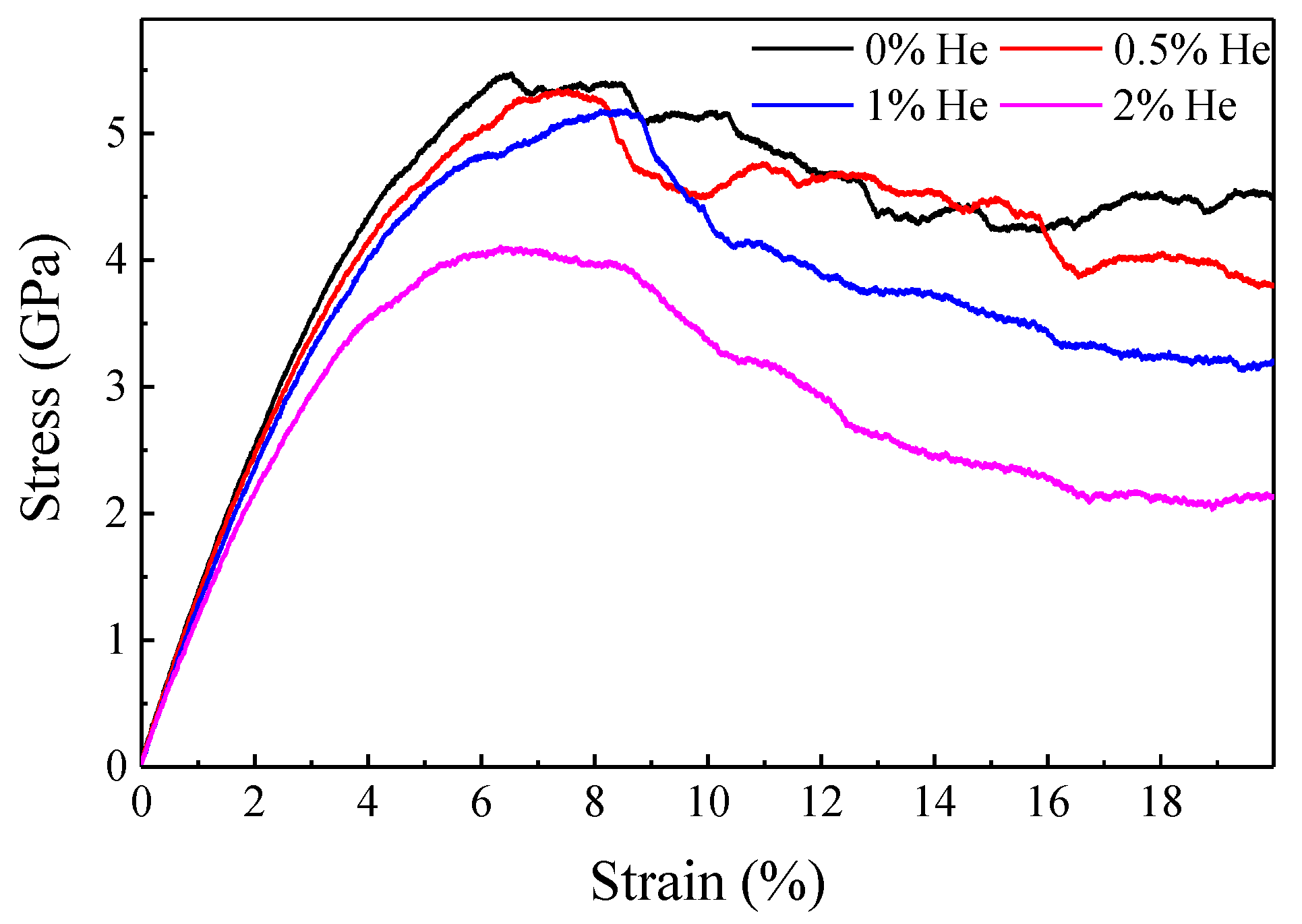
Figure 1 presents the stress–strain curves of the nanocrystalline Fe with different He concentrations. It is observed that both the peak stress and the elastic modulus decrease with the increasing concentration of GB He, indicating that mechanical properties of the nanocrystalline Fe are weakened by GB He. This result is in good consistence with the previous study on nanocrystalline W [29].
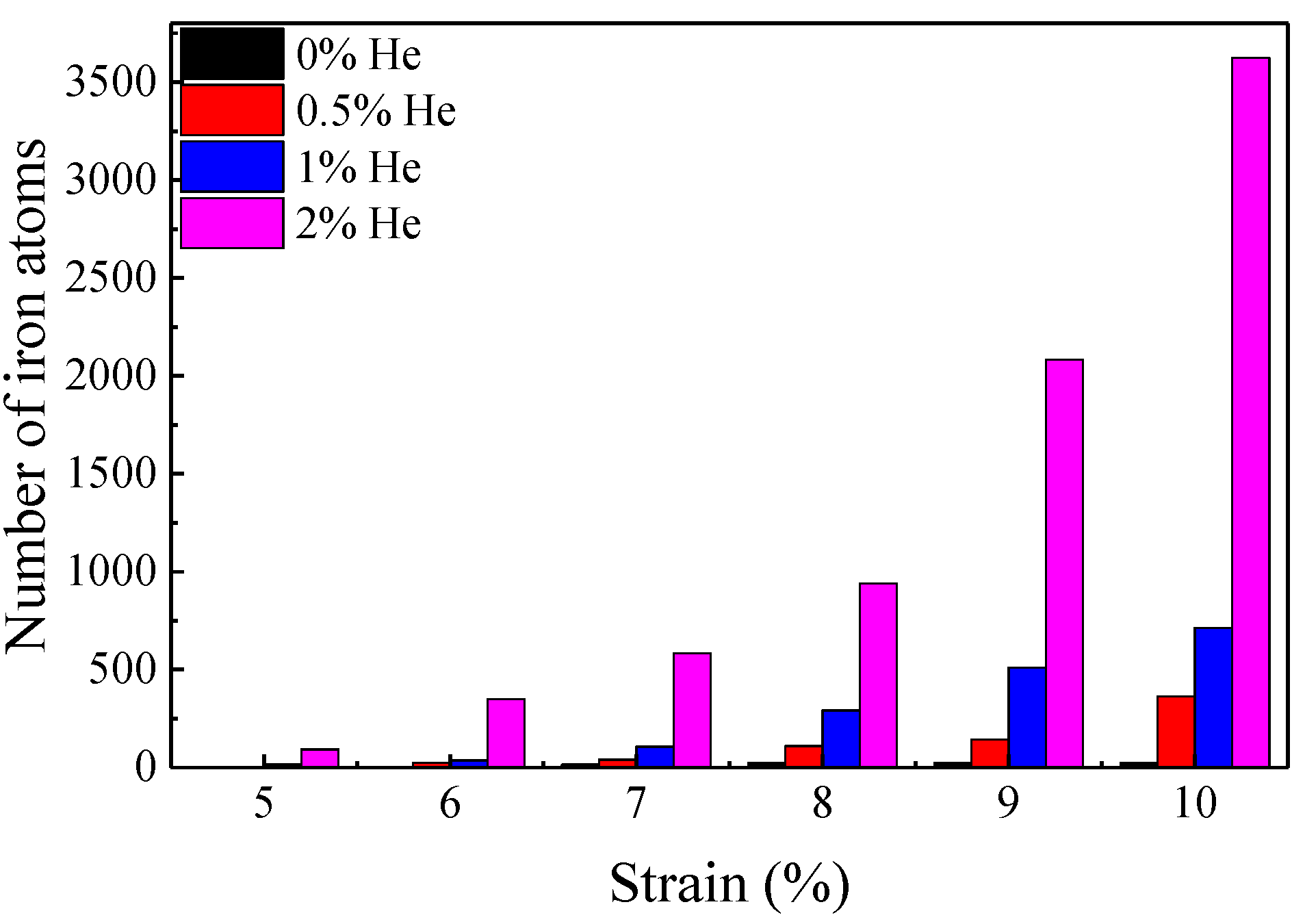
The generation of cracks is one of the important factors leading to the degradation of mechanical properties. In the present study, the intergranular cracks are observed during deformation, which agrees with previous studies very well [12,22,30]. In order to understand the He effects on the mechanical properties of nanocrystalline Fe, the evolution of the cracks in nanocrystalline Fe as a function of He concentration are investigated. Generally, the generation of cracks initially begins with the decrease in the atomic number density in a certain volume of nanocrystalline Fe, so the atomic volume of the Fe atom was calculated by OVITO. Due to the cracks that are surrounded by Fe with an atomic volume not less than about 16 Å3 (this is the biggest atomic volume in nanocrystalline Fe before loading), the Fe with a larger atomic volume (>16 Å3) was counted to study the generation and growth of cracks.
The number of Fe atoms near the biggest crack in nanocrystalline Fe is shown in Figure 2. It is observed that, at a given He concentration, the number of Fe atoms increases with the increasing strain, and the critical strain for crack formation is about 5–6%. What is more, a higher He concentration leads to bigger cracks in nanocrystalline Fe deformed to a certain strain, implying that crack formation is promoted by GB He.
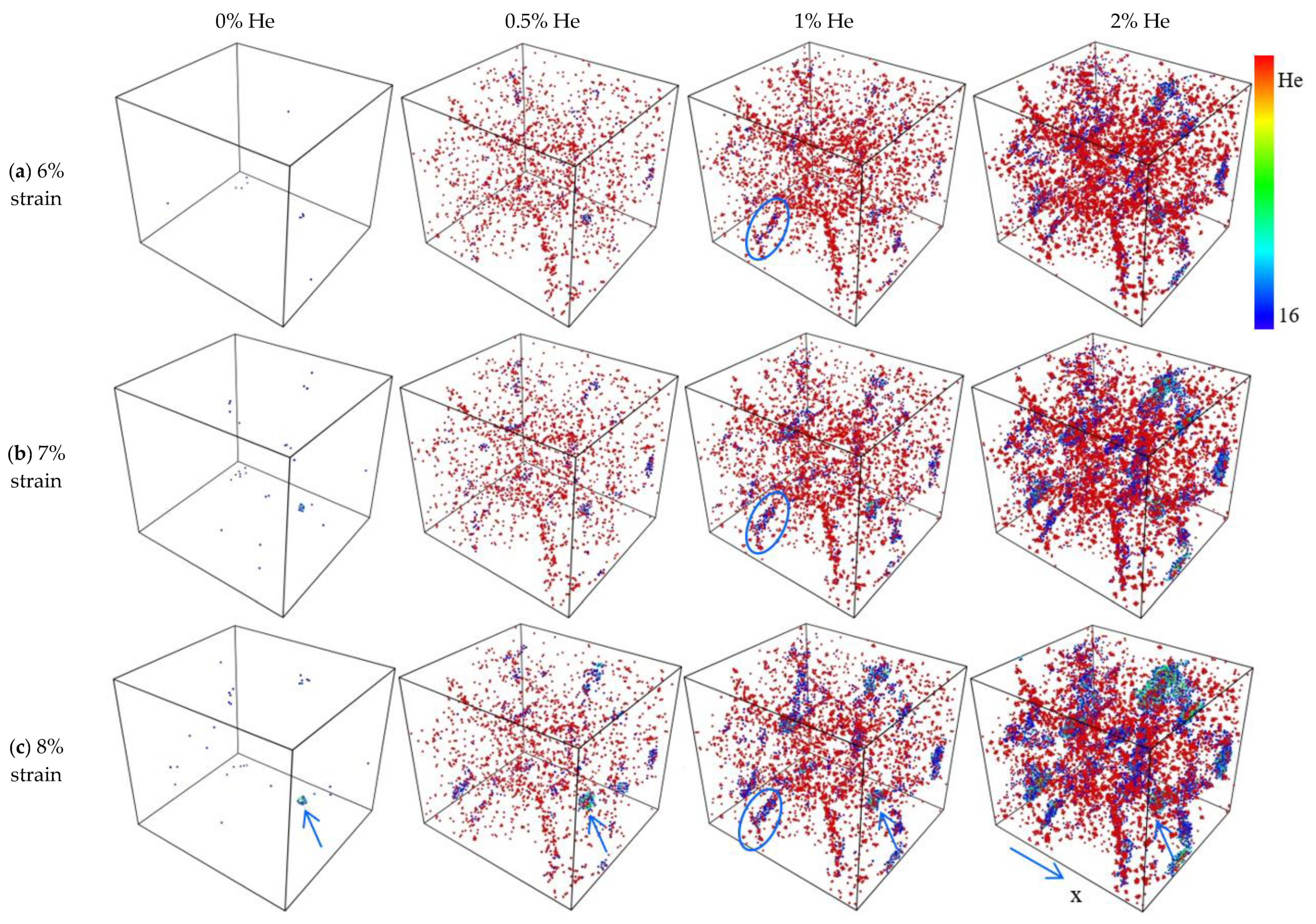
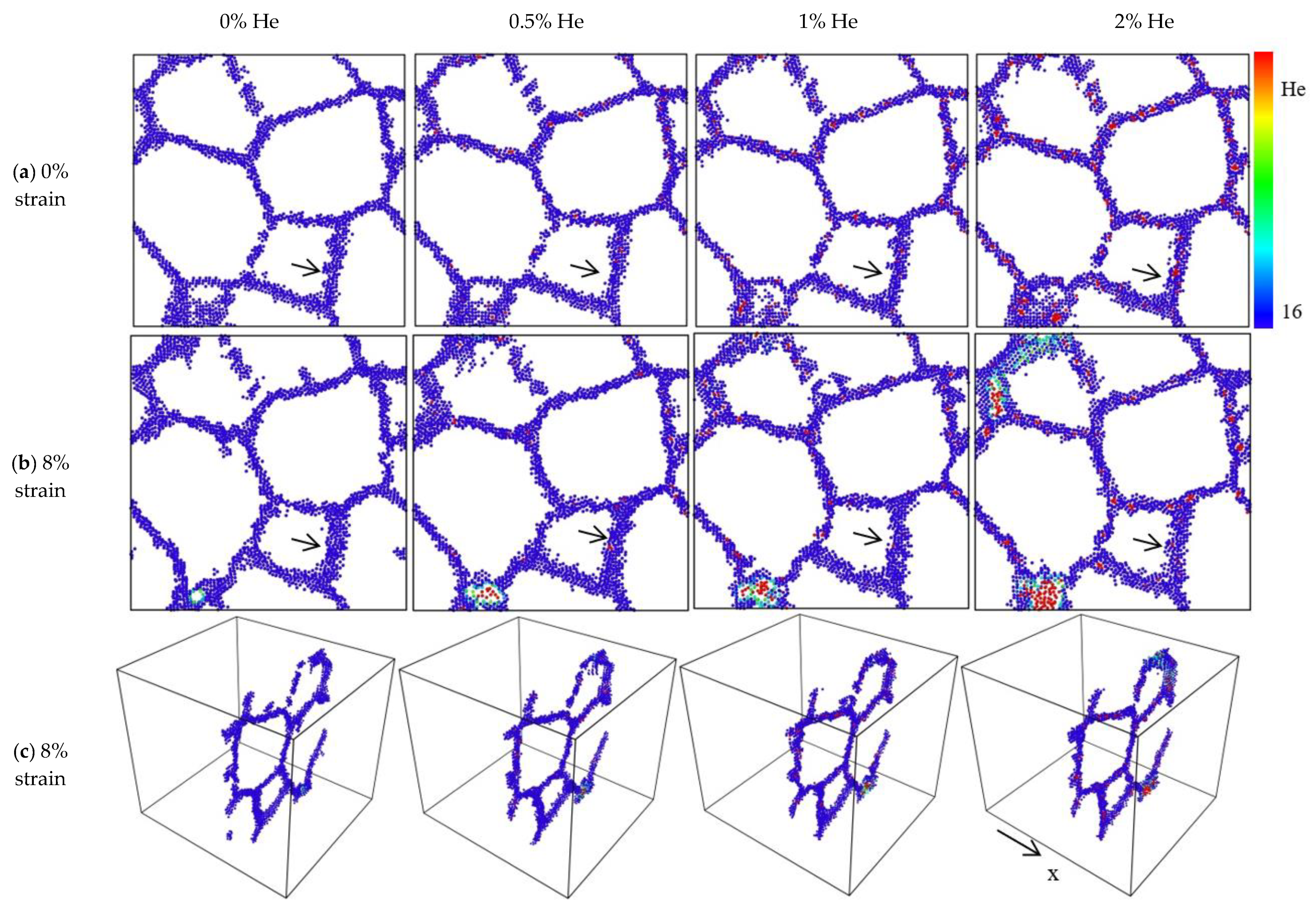
Figure 3 shows the cracks in nanocrystalline Fe with different He concentrations and strains. In order to illustrate the cracks clearly, only the iron atoms near the cracks and the He atoms distributed in the GB region are shown. According to the statistical results in Figure 2, the generation and growth of the cracks is found to be in a strain interval of about 6–8%, so the evolution of cracks in this strain range is focused. It is observed in Figure 3 that the generation of intergranular crack sources increases with increasing strain in the range of 6–8%. Both the crack size and density increase with the increasing concentration of GB He in the nanocrystalline Fe, meaning that the generation of cracks is significantly promoted by GB He (see cracks labeled with blue arrow). In addition, a more obvious connection of small cracks (see cracks labeled by blue circle) is found in the nanocrystalline Fe with a higher He concentration. Essentially, this is due to the GB strength being weakened by GB He [11]. The deformations of the grains are coordinated with each other during loading; hence, the generation of cracks corresponds to the saturation of grain deformation. That is to say, the deformation of some grains is no longer smooth as the concentration of GB He increases, due to the generation of cracks promoted by GB He.
3.2. He Effects on the Crystal Structure and GB Structure
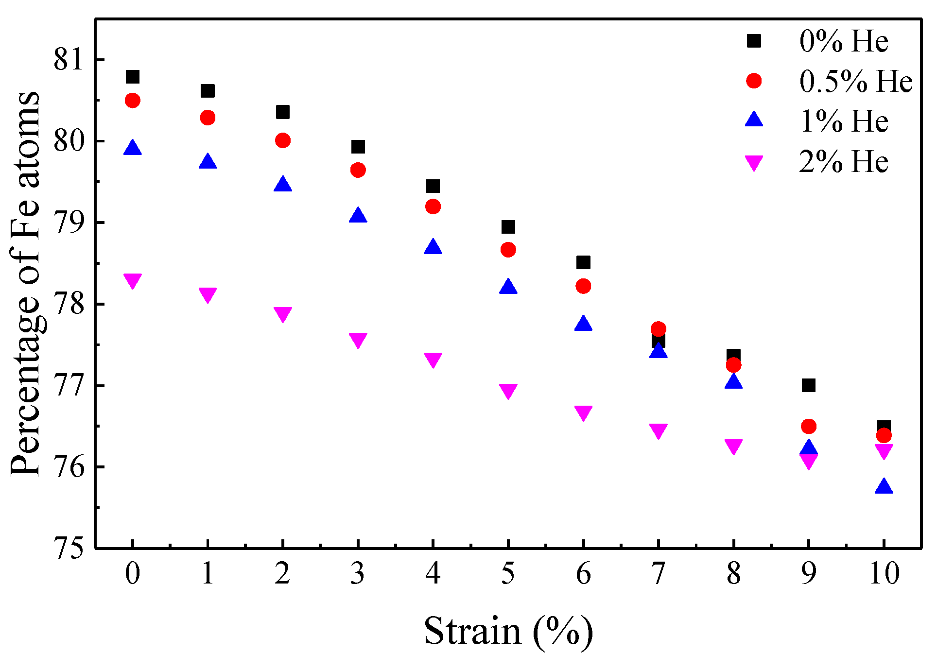
For the nanocrystalline Fe with a certain concentration of GB He, the statistical results in Figure 4 show that the percentage of Fe in the BCC region deceases with the increase in strain before the peak stress is loaded on. It is also found that the percentage of Fe in the BCC region is reduced with the increasing concentration of GB He in the strain range of 0–6%. In other words, part of the BCC region is changed to a non-BCC structure during the process of deformation. The perfect crystal structure is observed in the inner-grain region in the strain range of 0–6%, so the Fe atoms that have relaxed away from the ideal lattice sites are located at the region between the BCC region and the GB region during loading. It is indicated that the GB region and BCC region are deformed cooperatively with the increase in the strain. Due to the percentage of Fe atoms in the BCC region being changed by GB He, the deformation behavior of nanocrystalline Fe is affected by GB He during loading.
According to the calculation results in the strain range of 0–6%, as shown in Figure 4, the variations in the percentage of Fe atoms in the BCC region are 2.28%, 2.28%, 2.16% and 1.77%, for the nanocrystalline Fe with a He concentration of 0%, 0.5%, 1% and 2%, respectively. Therefore, the variation in the percentage of Fe in the BCC region decreases with the increasing He concentration. Combining the simulation results in Figure 1 and Figure 4, it is demonstrated that a larger variation in the percentage of Fe in the BCC region shows better mechanical properties. Therefore, the GB He reduces the saturation point of deformation during loading.
In order to investigate the He effects on the structure of GB, the Fe atoms and He atoms in the GB region of nanocrystalline Fe are shown in Figure 5. As a contrast, the GB structure of nanocrystalline Fe without loading is shown in Figure 5a. The GB structures of nanocrystalline Fe with different He concentrations deformed to 8% are shown in Figure 5b, and the corresponding three-dimensional version is exhibited in Figure 5c. It is observed that the GBs labeled by the black arrow are gradually thickened as the strain increases up to 8%, and these GBs nearly perpendicular to the loading direction are thicker than those parallel to the loading direction. In addition, the GBs nearly perpendicular to the direction of the tensile loading are more vulnerable, as compared with other grain boundaries. For example, as shown in Figure 3, the intergranular fracture in the GB region grows up along the direction nearly perpendicular to the loading direction. Therefore, it is deduced that the direction of the GBs plays a key role in the generation of cracks. A similar result has been reported in a previous study [24], that the tensile strength depends on the orientation of GBs in nano-twinned BCC Fe.
Figure 5b shows that the size of the intergranular cracks increases with the increasing concentration of GB He, and the existence of He clusters inside the cracks is observed. It is also seen from Figure 5a that the He clusters are gradually obvious with the increase in the He concentration in nanocrystalline Fe. That is to say, the GB structures are changed by He, which contributes to the degradation of the mechanical properties. For all simulation models, the GBs and their triple junction migration are observed during loading [12].
3.3. He Effects on the Crystal Structure of BCC Region
The simulation results in the above sections show that the structure of the BCC region and GB region is modified with the generation of cracks in nanocrystalline Fe. In this section, the simulated XRD method is used to explore the relationship between the generation of cracks and the change in the crystal structure during loading.
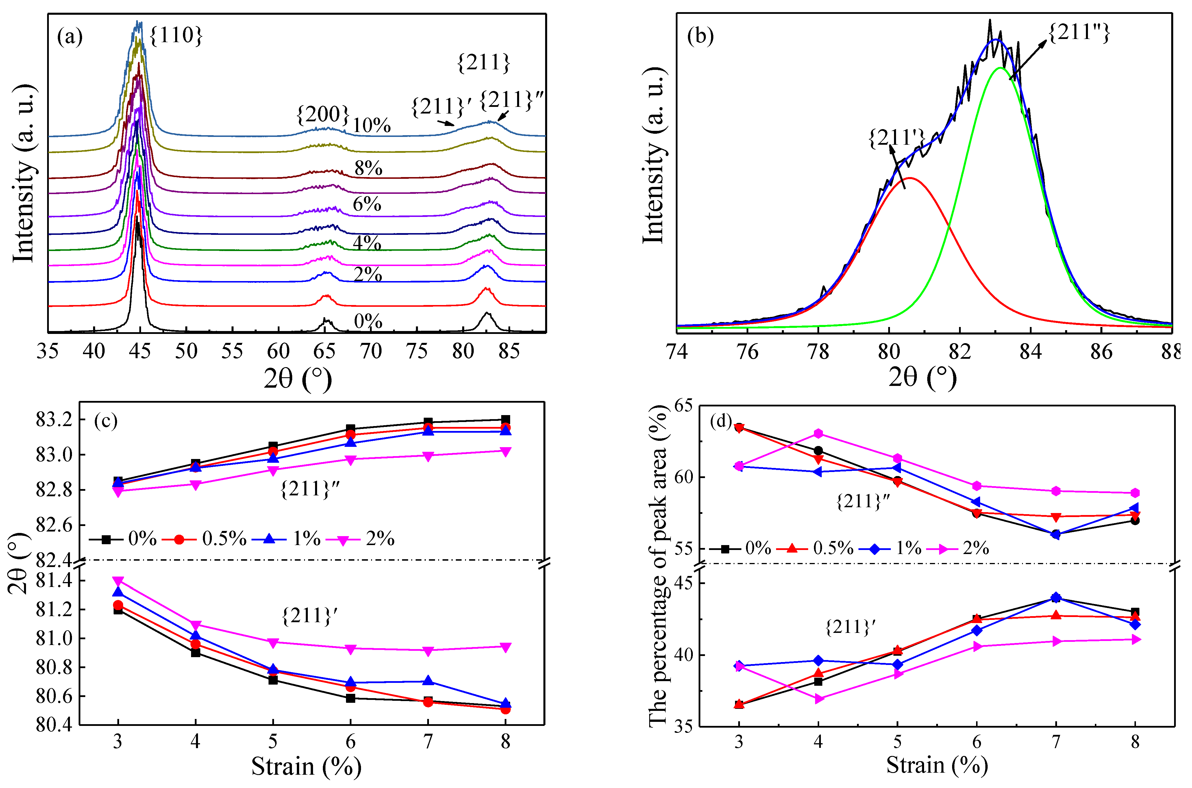
Figure 6a shows the simulated XRD patterns of nanocrystalline Fe without GB He. The simulated XRD patterns of nanocrystalline Fe before loading is in accord with the previous experimental results reported by Yu et al. [7]. The peak splitting of the XRD patterns is obviously observed in the strain interval of 3–10%, implying that the structure of the BCC region is distorted during loading. The simulated XRD patterns of nanocrystalline Fe with different He concentrations show a similar peak splitting. In addition, the degree of lattice distortion revealed by the peak splitting of the XRD patterns is non-homogeneous. Considering the diffraction peak with a high angle is changed more dramatically than those with low angles, the separation of the {211} peak is analyzed in detail to describe the microstructure change affected by GB He in the deformation process. It is observed in Figure 6a that the {211} peak gradually splits into two peaks with the increasing strain. For simplicity, the left sub-peak of {211} is labeled by {211}′, and the right peak is labeled by {211}″. Moreover, there is a left shift of the {211}′ peak and a right shift of the {211}″ peak in the strain interval of 3–6%. Under further strain of 6–10%, recovery of the {211}′ peak is observed, which is ascribed to the recovery of lattice distortion caused by the generation of cracks.
In order to further analyze the change in the peak position, the diffraction peaks of {211} are fitted with two peaks ({211}′ and {211}″) using the Voigt function, as shown in Figure 6b. Based on the fitting results, the peak position and area of {211}′′ and {211}″ as a function of the strain are calculated and shown in Figure 6c,d, respectively.
It can be seen from Figure 6c that, with the strain increasing up to 6%, the {211}′ peak shifts to a lower 2θ, while {211}″ shifts to a higher 2θ. In the strain range of 6–8%, there is a small fluctuation in the positions of the {211}′ and {211}″ peaks. The shift to a higher 2θ of the {211}″ peak means the corresponding interplanar spacing is reduced, and the shift to a lower 2θ of {211}′ means the reverse happens in nanocrystalline Fe. Thus, the structural distortion increases with the increasing strain. What is more, the difference in the peak position between {211}′ and {211}″ decreases with the increasing concentration of GB He. Therefore, it means that the GB strength is too small to support the further change in the interplanar spacing after the introduction of GB He.
It is shown in Figure 6d that the peak area of {211}′ increases with the increasing strain if the He concentration remains unchanged, while decreases roughly with the increasing He concentration at a given strain. In other words, the fraction of the lattice distortion is increased with the deformation of nanocrystalline Fe and is reduced with the increasing He concentration.
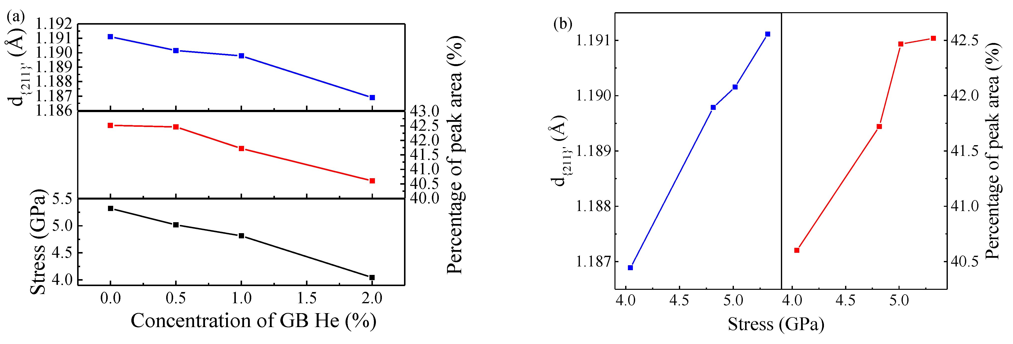
From Figure 6c,d, it is found that the He effects on the peak position and area have a regular trend in the strain range of 5–6% (close to the peak stress). For the nanocrystalline Fe deformed to a 6% strain, as shown in Figure 7a, the crystal spacing d{211}′, the peak area and the loading stress decrease linearly with the increase in the He concentration. The crystal spacing represents the degree of lattice distortion, and the peak area represents the fraction of lattice distortion. The generation of cracks increases with the increasing He concentration, and both the degree and fraction of the lattice distortion are reduced. As shown in Figure 7b, the degree and fraction of lattice distortion increase linearly with the increasing loading stress of nanocrystalline Fe with GB He.
4. Conclusions
The MD simulation was carried out to study the He effects on the mechanical properties of nanocrystalline BCC iron. The peak stress and the elastic modulus decrease with the increasing concentration of GB He. The higher He concentration leads to a greater crack density and size in nanocrystalline Fe. The GBs nearly perpendicular to the direction of the tensile loading are more vulnerable compared with other grain boundaries. The degradation of the mechanical properties of nanocrystalline Fe with GB He is related to the separation of the peaks in the simulated XRD patterns. The lower peak position of {211}′ suggests a more serious lattice distortion during loading. The generation of cracks leads to the reduction in peak stress and the degree and fraction of the lattice distortion. For all nanocrystalline Fe deformed to a 6% strain, the degree and fraction of the lattice distortion increases with the increasing loading stress.
Author Contributions
Conceptualization, C.X.; investigation, C.X. and D.Y.; software, C.X.; visualization, C.X.; writing—original draft, C.X. and D.Y.; writing—review and editing, C.X. and D.Y. Both authors have read and agreed to the published version of the manuscript.
Funding
This research was funded by the National Natural Science Foundation of China (11805088) and the Science Foundation for Youths of Gansu Province (20JR5RA230).
Institutional Review Board Statement
Not applicable.
Informed Consent Statement
Not applicable.
Data Availability Statement
The data presented in this study are available on reasonable request from the corresponding author.
Acknowledgments
The authors acknowledge the support from the laboratory of computation science at Yantai University.
Conflicts of Interest
The authors declare no conflict of interest.
References
- Barnes, R.S. Embrittlement of Stainless Steels and Nickel-Based Alloys at High Temperature Induced by Neutron Radiation. Nature 1965, 206, 1307–1310. [Google Scholar] [CrossRef]
- Olander, D. Fundamental aspects of nuclear reactor fuel elements. Fundam. Asp. Nucl. React. Fuel Elem. 1976, 22, 258–259. [Google Scholar] [CrossRef]
- Kramer, D.; Brager, H.; Rhodes, C.; Pard, A. Helium embrittlement in type 304 stainless steel. J. Nucl. Mater. 1968, 25, 121–131. [Google Scholar] [CrossRef]
- Was, G.S. Fundamentals of Radiation Materials Science: Metals and Alloys. Mater. Today 2007, 10, 52. [Google Scholar] [CrossRef]
- Bai, X.-M.; Voter, A.F.; Hoagland, R.G.; Nastasi, M.; Uberuaga, B.P. Efficient Annealing of Radiation Damage Near Grain Boundaries via Interstitial Emission. Science 2010, 327, 1631–1634. [Google Scholar] [CrossRef]
- Chen, D.; Wang, J.; Chen, T.; Shao, L. Defect annihilation at grain boundaries in alpha-Fe. Sci. Rep. 2013, 3, srep01450. [Google Scholar] [CrossRef]
- Yu, K.; Liu, Y.; Sun, C.; Wang, H.; Shao, L.; Fu, E.; Zhang, X. Radiation damage in helium ion irradiated nanocrystalline Fe. J. Nucl. Mater. 2012, 425, 140–146. [Google Scholar] [CrossRef]
- Li, X.; Liu, W.; Xu, Y.; Liu, C.; Pan, B.; Liang, Y.; Fang, Q.; Chen, J.-L.; Luo, G.-N.; Lu, G.-H.; et al. Radiation resistance of nano-crystalline iron: Coupling of the fundamental segregation process and the annihilation of interstitials and vacancies near the grain boundaries. Acta Mater. 2016, 109, 115–127. [Google Scholar] [CrossRef]
- Zhang, L.; Shu, X.; Jin, S.; Zhang, Y.; Lu, G.-H. First-principles study of He effects in a bcc Fe grain boundary: Site preference, segregation and theoretical tensile strength. J. Phys. Condens. Matter 2010, 22, 375401. [Google Scholar] [CrossRef]
- Xu, C.; Liu, X.-Y.; Gao, F.; Li, Y.; Wang, Y. Modeling radiation damage near grain boundary in helium-doped α-iron. Nucl. Instrum. Methods Phys. Res. Sect. B Beam Interact. Mater. Atoms 2014, 332, 426–431. [Google Scholar] [CrossRef]
- Zhang, L.; Zhang, Y.; Geng, W.-T.; Lu, G.-H. Towards theoretical connection between tensile strength of a grain boundary and segregated impurity concentration: Helium in iron as an example. EPL Europhys. Lett. 2012, 98, 17001. [Google Scholar] [CrossRef]
- Farkas, D.; Van Swygenhoven, H.; Derlet, P.M. Intergranular fracture in nanocrystalline metals. Phys. Rev. B 2002, 66, 060101. [Google Scholar] [CrossRef] [Green Version]
- Terentyev, D.; He, X. Effect of Cr precipitates and He bubbles on the strength of <110> tilt grain boundaries in BCC Fe: An atomistic study. Comput. Mater. Sci. 2011, 50, 925–933. [Google Scholar] [CrossRef]
- Suzudo, T.; Yamaguchi, M.; Tsuru, T. Atomistic modeling of He embrittlement at grain boundaries ofα-Fe: A common feature over different grain boundaries. Model. Simul. Mater. Sci. Eng. 2013, 21, 85013. [Google Scholar] [CrossRef]
- Huang, W.; Sun, M.; Yang, J.; Wen, W.; Xie, Z.; Zhang, L.; Liu, R.; Chen, C.; Jiang, Y.; Wang, X.; et al. Microstructure evolution of pure tungsten after low-energy and high-fluence He+ implantation assessed by synchrotron grazing incidence X-ray diffraction. J. Nucl. Mater. 2021, 544, 152663. [Google Scholar] [CrossRef]
- Qin, W.; Wang, Y.; Tang, M.; Ren, F.; Fu, Q.; Cai, G.; Dong, L.; Hu, L.; Wei, G.; Jiang, C. Microstructure and hardness evolution of nanochannel W films irradiated by helium at high temperature. J. Nucl. Mater. 2018, 502, 132–140. [Google Scholar] [CrossRef]
- Xu, C.; Wang, W. Simulation Study of Helium Effect on the Microstructure of Nanocrystalline Body-Centered Cubic Iron. Materials 2018, 12, 91. [Google Scholar] [CrossRef] [PubMed] [Green Version]
- Finney, J. A procedure for the construction of Voronoi polyhedra. J. Comput. Phys. 1979, 32, 137–143. [Google Scholar] [CrossRef]
- Plimpton, S. Fast Parallel Algorithms for Short-Range Molecular Dynamics. J. Comput. Phys. 1995, 117, 1–19. [Google Scholar] [CrossRef] [Green Version]
- Mendelev, M.I.; Han, S.; Srolovitz, D.J.; Ackland, G.J.; Sun, D.Y.; Asta, M. Development of new interatomic potentials appropriate for crystalline and liquid iron. Philos. Mag. 2003, 83, 3977–3994. [Google Scholar] [CrossRef]
- Malerba, L.; Marinica, M.; Anento, N.; Björkas, C.; Nguyen, H.; Domain, C.; Djurabekova, F.; Olsson, P.; Nordlund, K.; Serra, A.; et al. Comparison of empirical interatomic potentials for iron applied to radiation damage studies. J. Nucl. Mater. 2010, 406, 19–38. [Google Scholar] [CrossRef]
- Jeon, J.B.; Lee, B.-J.; Chang, Y.W. Molecular dynamics simulation study of the effect of grain size on the deformation behavior of nanocrystalline body-centered cubic iron. Scr. Mater. 2011, 64, 494–497. [Google Scholar] [CrossRef]
- Yuan, F. Atomistic simulation study of tensile deformation in bulk nanocrystalline bcc iron. Sci. China Ser. G Phys. Mech. Astron. 2012, 55, 1657–1663. [Google Scholar] [CrossRef] [Green Version]
- Zhao, X.; Lu, C.; Tieu, A.K.; Zhan, L.; Pei, L.; Huang, M. Deformation mechanisms and slip-twin interactions in nanotwinned body-centered cubic iron by molecular dynamics simulations. Comput. Mater. Sci. 2018, 147, 34–48. [Google Scholar] [CrossRef]
- Aziz, R.A.; Janzen, A.R.; Moldover, M.R. Ab InitioCalculations for Helium: A Standard for Transport Property Measurements. Phys. Rev. Lett. 1995, 74, 1586–1589. [Google Scholar] [CrossRef]
- Gao, F.; Deng, H.; Heinisch, H.; Kurtz, R. A new Fe–He interatomic potential based on ab initio calculations in α-Fe. J. Nucl. Mater. 2011, 418, 115–120. [Google Scholar] [CrossRef]
- Stukowski, A. Visualization and analysis of atomistic simulation data with OVITO–the Open Visualization Tool. Model. Simul. Mater. Sci. Eng. 2009, 18, 015012. [Google Scholar] [CrossRef]
- Coleman, S.; Spearot, D.E.; Capolungo, L. Virtual diffraction analysis of Ni [0 1 0] symmetric tilt grain boundaries. Model. Simul. Mater. Sci. Eng. 2013, 21, 55020. [Google Scholar] [CrossRef]
- Zhu, F.; Wang, N.; Gao, N.; Peng, H.; Xie, Z.; Zhang, Z. Microstructure evolution and Young’s modulus of He-implanted nanocrystalline tungsten film. J. Nucl. Mater. 2019, 518, 226–233. [Google Scholar] [CrossRef]
- Latapie, A.; Farkas, D. Molecular dynamics investigation of the fracture behavior of nanocrystallineα-Fe. Phys. Rev. B 2004, 69, 134110. [Google Scholar] [CrossRef] [Green Version]
Figure 1.
The stress–strain curves of nanocrystalline Fe with different He concentrations.

Figure 2.
The number of Fe atoms near the biggest crack as a function of strain. No cracks are found during 0–4% straining.
Figure 2.
The number of Fe atoms near the biggest crack as a function of strain. No cracks are found during 0–4% straining.

Figure 3.
The generation of crack in the model deformed to (a) 6% strain; (b) 7% strain; (c) 8% strain. The concentration of He are label in the picture. The red represents He atom and the Fe atoms are colored according to atomic volume, see the color bar. The loading direction is parallel to x-axis.

Figure 4.
The percentage of iron atoms in BCC region as a function of strain.

Figure 5.
The cross sections of nanocrystalline BCC Fe: (a) before loading; (b) deformed to 8% strain; and (c) deformed to 8% strain. The loading direction is parallel to x-axis. The Fe atom in BCC region is filtered out for clarity. The red represents He atom and the Fe atoms are colored according to atomic volume, see the color bar.

Figure 6.
(a) The simulated XRD patterns of the nanocrystalline Fe in a strain interval of 0–10%; (b) the {211} peak and the fitting result by two peaks for the nanocrystalline pure Fe deformed to 6%;(c) the peak position of {211}′ and {211}″ as a function of strain; and (d) the peak area of {211}′ and {211}″ as a function of strain.

Figure 7.
(a) The crystal spacing d{211}′, the peak area of {211}′ and the stress as a function of He concentration for nanocrystalline Fe deformed to 6%; and (b) the crystal spacing d{211}’ and the peak area of {211}′ as a function the stress for nanocrystalline Fe deformed to 6%.
Figure 7.
(a) The crystal spacing d{211}′, the peak area of {211}′ and the stress as a function of He concentration for nanocrystalline Fe deformed to 6%; and (b) the crystal spacing d{211}’ and the peak area of {211}′ as a function the stress for nanocrystalline Fe deformed to 6%.

Publisher’s Note: MDPI stays neutral with regard to jurisdictional claims in published maps and institutional affiliations. |
© 2021 by the authors. Licensee MDPI, Basel, Switzerland. This article is an open access article distributed under the terms and conditions of the Creative Commons Attribution (CC BY) license (https://creativecommons.org/licenses/by/4.0/).
Share and Cite
MDPI and ACS Style
Xu, C.; Yang, D. Helium Effects on the Mechanical Properties of Nanocrystalline Fe: Based on Molecular Dynamics. Crystals 2021, 11, 532. https://0-doi-org.brum.beds.ac.uk/10.3390/cryst11050532
AMA Style
Xu C, Yang D. Helium Effects on the Mechanical Properties of Nanocrystalline Fe: Based on Molecular Dynamics. Crystals. 2021; 11(5):532. https://0-doi-org.brum.beds.ac.uk/10.3390/cryst11050532
Chicago/Turabian StyleXu, Chunping, and Dongyan Yang. 2021. "Helium Effects on the Mechanical Properties of Nanocrystalline Fe: Based on Molecular Dynamics" Crystals 11, no. 5: 532. https://0-doi-org.brum.beds.ac.uk/10.3390/cryst11050532
Note that from the first issue of 2016, this journal uses article numbers instead of page numbers. See further details here.