Mode-Independent and Mode-Interactive Failure Criteria for Unidirectional Composites Based on Strain Energy Density


College of Mechanical and Power Engineering, Nanjing Tech University, Nanjing 211816, China
*
Author to whom correspondence should be addressed.
Polymers 2020, 12(12), 2813; https://0-doi-org.brum.beds.ac.uk/10.3390/polym12122813
Submission received: 28 October 2020
/
Revised: 21 November 2020
/
Accepted: 25 November 2020
/
Published: 27 November 2020
(This article belongs to the Special Issue Fiber-Reinforced Composites: Innovative Solutions and Advanced Analysis Methods)
Abstract
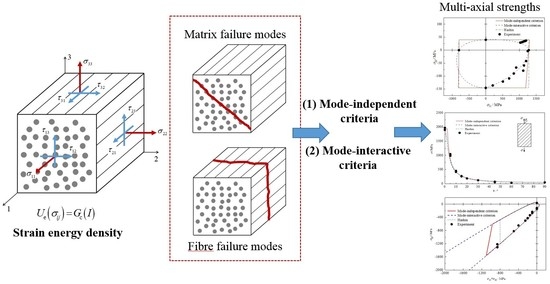
:The strain energy released plays a crucial role in generating macroscopic failure in unidirectional (UD) composites. This paper proposes two new strain energy-based failure criteria, regarding fiber-dominated and matrix-dominated failure mode as independent and interactive, respectively. The failure expression is formulated based on rigorous mathematical deducing, accompanied by physical interpretation. Based on the lack of experimentally feasible multi-axial strengths, a predefined assumption of infinite strength under bi-axial and tri-axial compressive stress provides the possibility for determining all coefficients only by using conventional uniaxial strengths. The failure envelopes predicted by the proposed criteria have been validated against experimental results under biaxial, off-axis and tri-axial loading cases. A better agreement with physical reality was achieved by the failure mode-interactive criterion, suggesting a wide range of applicability.
1. Introduction
Failure theories, which can be classified as either being macroscopic or microscopic, have been an utmost crucial issue in scientific research and even more so in engineering practice since the widespread application in advanced composites. Through the series of World Wide Failure Exercises (WWFEs) spanning the past two decades [1,2,3,4], the state-of-the-art has been well-reflected in an objective manner. Macroscopic failure criteria, which are widely used in engineering practice, are classified into three groups. The criteria in the first group predict failure status by directly comparing stresses (or strains) with respective strengths. The representatives are the maximum stress and the maximum strain criteria.
Since the above strength limit criteria neglect interactions of stress or strain components, failure theories of the second group are proposed to consider full stress interaction by employing a single quadratic or higher-order polynomial function of all potential stresses. Tsai and his co-workers originally proposed one of the most famous criteria of a single expression, i.e., the Tsai–Wu failure criterion [5]. Although the Tsai–Wu criterion has achieved great success over the past decades, it has been subjected to criticisms for being non-phenomenological or empirical [6]. These criteria of single expression fundamentally combine distinctive fracture mechanisms occurring within unidirectional (UD) composite materials, therefore, the debate on rationalism and robustness for failure predictions is to continue due to different mechanisms found at the microscale [7]. Moreover, such criteria are unable to distinguish internal failure modes that may cause difficulties in the subsequent analysis of failure evolution.
The third group refers to phenomenological failure criteria that are based on physical aspects of fracture. The Hashin failure theory [8,9] made a significant contribution to the formulation of composite failure criteria by employing a solid physical basis instead of purely empirical curve fitting. It initially separated different modes of failure by defining corresponding stress invariants. The classification regarding the failure of fibre reinforced plastic (FRP) composites (i.e., matrix cracking in tension and compression and fiber damage in tension and compression) is usually adopted and has inspired, or laid a basis for follow-up studies [10]. Despite extensive selection in engineering due to its simplicity of concept, Hashin’s work could not present a reasonable interpretation of the shear fracture impeding influence induced by a moderate transverse compressive stress [11]. Moreover, some inconceivable results, from the physical point of view, may be gained since some arbitrary measures were taken, as discussed in [12]. Following Mohr’s fracture hypothesis stating that failure would be exclusively caused by the stresses acting on the fracture plane, Puck and Schurmann [13] introduced the concept of the fracture plane into their phenomenological failure model. Puck’s criterion not only predicts the stress level leading to crack initiation but also provides the results of crack direction. It was ranked highly among all the nineteen participants in the WWFEs, and therefore, was suggested by organizers [2]. A further modification, with high relevance to Puck’s theory, was performed by incorporating in situ effects, shear nonlinearity and fiber kinking mechanisms [14,15]. However, additional employment of artificially defined parameters, e.g., inclination parameters, may cause disputes over the determination of their specific values [16].
So far, the majority of current phenomenological failure criteria for UD composites are constructed based on stresses/strains, e.g., stress invariants [9,17,18,19] or stresses acting on the fracture plane [11,13,14,15]. Nevertheless, despite remarkable success achieved and convincing physical meaning in the definition of failure-induced stress, it should be emphasized that the choice of quadratics is not based on physical reasoning but curve fitting considerations [9]. There has been an issue of the failure theories which has never been thoroughly investigated, and that is the physical interpretation of the order of failure equations. The only explanation provided is that quadratic polynomials can fit test data well, indicating no need to employ cubic or higher approximations. The authors would argue the rationality existing in the explanation and the form as these criteria are proposed. Even though failure theories fall in the category of phenomenological approaches, it should be clarified that this assumption remains empirical or artificial, no matter how rational the subsequent deduction is in the formulation of the criteria. Within the theoretical framework constructed by the stress invariant-based approach, it hardly seems capable to “physically” explain why cubic or higher approximations are not employed. It seems feasible to formulate a strain energy density criterion due to the quadratic nature of stress-energy density forms.
The macroscopic material failure, from a thermodynamic point of view, is the final consequence of an energy-driven destabilization process and is associated with the collective disruption of atomic bonds that is driven by the potential energy stored in the atomic bonds. In a mechanical system, a universal failure criterion at the macroscopic scale can be defined by a specific elastic strain energy density with its threshold value [20]. Efforts have been made to investigate the fracture behaviors of isotropic materials by using the energy concept. However, if the attention is shift to UD fiber-reinforcement composite materials, quite limited literature has been reported based on the strain energy release. The Tsai–Hill criterion is the extension of the classical von Mises yield condition to orthotropic materials [21]. The main deficiency is that it cannot identify the difference of strengths in tension and compression. Wolfe et al. [22,23] developed a strain energy-based failure model to predict failure behaviors of composites under multi-axial loadings, taking into account the effect of hydrostatic stress. But there would be no experimentally feasible scheme to measure certain parameters, which are introduced in their criterion to define the shape of the failure surface in strain energy space.
For the existing failure criteria that divide composite failure into fiber-dominated and matrix-dominated damage modes, conventionally most of them (e.g., the Hashin’s criterion and Puck’s criterion) accept the hypothesis that fiber fracture and matrix cracking may be mutually independent. This hypothesis is proposed based on the fact that the potential fracture planes regarding matrix and fiber failure are perpendicular, but it has been questioned by a series of experimental evidence [24]. This phenomenon is attributed to the mutual influence of localized micro-damages. Taking fiber failure, for example, it should be noted that micro-fractures of some fiber elements have already occurred before the lamina reaches its macroscopic strength. The existence of microfiber fractures will induce micro-cracks in the neighboring matrix and debonding of fiber–matrix interfaces. Besides, the ability to resist fiber failure will be weakened due to the effects of defects. Even under transverse stress, micro-cracks, initiating in the region of defects, may propagate along the fibers. To establish a more reasonable criterion at the macroscale, the interactions of micro-damages are required to be characterized from a macroscopic perspective. Hence Puck used a degradation factor to consider the weakening effect. The major drawback, however, is the lack of reliable experimental or mathematical methods to obtain the specific value of that factor.
The objective of the present paper was to propose new three-dimensional failure criteria for UD composites from a strain energy release point of view. The formulation of the failure expression is logically deduced based on physical interpretation, rather than through curve fitting considerations made by stress invariant-based criteria (e.g., Hashin’s criterion). Also, a mode-interactive model is further proposed to characterize the micro-interactions of matrix-dominated and fiber-dominated failure modes in the view of the macro level. For both mode-independent and mode-interactive criteria, all parameters required can be determined by conventional strength properties at the UD-lamina level, without making any assumption sometimes arguable. Finally, the present failure criteria are validated and compared, in terms of failure envelopes, by measurements in biaxial, off-axis tension and tri-axial experiments.
2. Failure Mode-Independent Criterion Based on Strain Energy Release
The thermodynamics of irreversible processes, regarding energy conversion as an essential physical process, is a rational framework that can be applied to formulate failure criterion. Neglecting thermal effects, the mechanical work of the external load, W, is converted to the elastic strain energy and the dissipated energy in a closed system. According to the first law of thermodynamics, it assumes
where irreversible denotes the plastic deformation and the internal damage induced by micro-cracks or defects inside a material element, while is releasable and reversible energy. When a material is subjected to the external load, some fraction of the mechanical work imposed on the UD composite is converted into the dissipated energy, which leads to a progressive deterioration in the cohesion of microscopic structures and corresponds to a nonlinear stress–strain behavior at the macro scale. Since material failure at different levels has different physical meanings, it should be noted that such degradation in mechanical properties of micro material elements does not necessarily imply a material failure on a macroscopic level. Taking uniform tri-axial compression for example, despite the property deterioration caused by micro damages at the microscopic level, a UD composite may not fail due to the pressure effect. Moreover, given that the intrinsic dissipation during a material brittle failure is negligible, a specified elastic strain energy is suggested to macroscopically represent a failure of using the energy density concept to define a universal macroscopic failure criterion [20]. For a UD composite under a general stress state in a Cartesian coordinate, its total elastic strain energy is defined as
where is the elastic strain. The Cartesian coordinate system is defined as follows: 1-direction corresponds to the fiber direction, 2-direction lies perpendicular to the fiber direction and 3-direction goes along the thickness-direction of the single layer. Given transverse isotropy that is usually sufficient to characterize behaviors of UD composites, Equation (2) can be further written as
where represent the components of the compliance matrix for a transverse isotropic material.
As long as the stored strain energy reaches a critical value , it will be suddenly released, resulting in macroscopic failure. Specifically for brittle material, of which failure is independent of deformation history, the criterion may be generalized as
If the critical strain energy is assumed to be constant, a simple criterion can be constructed by substituting Equation (3) into Equation (4). That is
It is not surprising that Equation (5) reproduces a standard stress form of the classical Tsai–Hill failure criterion [21], since the Tsai–Hill criterion is the extension of the distortion strain energy-based von Mises yield condition to orthotropic materials. Nevertheless, such an assumption indicates the identical tensile and compressive nature of UD composite failure. Therefore, in principle, the present form of Equation (5) could only predict macroscopic failure of the composite material with exactly the same released strain energy or strength under tension and compression. Another main irrationality of this assumption may be the combination of fundamental fracture mechanisms that are distinct. The critical energy release corresponding to the fiber fracture (e.g., uniaxial tension along the longitudinal direction) is different from that corresponding to the matrix cracking (e.g., pure transverse shear). The above analysis shows that the simple assumption of as a constant is improper, the physical meanings underlying is not in satisfying agreement with the observation of actual composite failure mechanisms. As a result, in an attempt to provide reasonably rational physical explanations, the specific form of should meet the following conditions:
(a) In contrast to isotropic materials, the heterogeneous nature of UD fiber reinforcement composites indicates that there are two primary failure modes on the lamina level, i.e., longitudinal, fiber-dominated failure mode and matrix-dominated failure mode. So the critical energy release corresponding to different failure modes naturally comes different.
(b) The release of strain energy stored in composite materials is related to tension stress and compression stress, whereas pure shear stresses with opposite orientation play an identical role in failure formation, namely having the same critical strain energy.
(c) It seems impossible to neglect the effect of the hydrostatic stress on mechanical behavior, as polymers exhibit clear sensitivity to hydrostatic pressure. Experimental investigation on the effects of hydrostatic pressure has found that the transverse compression modulus increased markedly with pressure, while a slight increase appeared in the longitudinal modulus [25]. The phenomenon suggests that the volume change associated with hydrostatic stress may significantly affect the strain energy corresponding to transverse matrix failure modes.
As a consequence, a failure criterion is to be formulated from the viewpoint of energy, to distinguish between longitudinal, fiber-dominated failure mechanisms and transverse, matrix-dominated failure mechanisms on the lamina level. In general, it is appropriate to use four different formulas to describe these two primary modes induced by tension and compression.
2.1. Fibre Failure Mode
For the fiber failure mode, the failure plane is about the 2–3 plane [26]. The strain energy, , producing this type of failure may be correlated with , and , resulting in the fiber-controlled failure criterion as
where () is the first stress invariant with respect to the preferred direction coinciding with the 1-direction. The superscript ‘int’ denotes the initial status with . is the functional relation for the initial longitudinal elastic modulus, , (where ) and under hydrostatic stress (where ). Tensile fiber failure and compressive fiber failure are denoted by superscripts and , respectively. Rearranging Equation (6) turns into
where the superscript ‘int’ is neglected for the sake of simplification. According to the experimental observation that longitudinal elastic modulus is insensitive to hydrostatic stress, i.e., , the critical strain energy related to fiber tensile and compressive failure is approximately constant, namely
By applying pure longitudinal shear strength, , to Equation (7), it follows
Utilizing failure data of uniaxial stress state in Equation (7) results in
where and are tensile and compressive failure stress in the fiber direction, respectively. Contradiction, however, emerges in most cases where the magnitude of is not equal to but higher than that of . Thus rationally, the term of shear stress and is demonstrated to be not in the criterion regarding fiber failure. Equation (7) is then degenerated into
This conclusion is not only correct mathematically but has physical meanings as well. It can be explained that in the case of pure longitudinal shear ( or ), the strain energy required for shearing off fibers is much higher than shearing off of matrix. In other words, the energy stored in composite materials would be easier to release in the way of matrix cracking. Many micromechanical analyses [27,28,29] have also reported that the longitudinal shear loading would cause matrix cracking or fiber–matrix debonding at the 1-2 or 1-3 plane rather than shear-driven fiber breakage on the 2–3 plane. In addition, this inference is proved through the conclusions of Atas’s [30] and Tserpes’s work [31]. Both pieces of research have shown that fiber damage would be typically overestimated, once the conventional shear strength is applied in shear stress terms of the Hashin-type fiber tensile failure criterion. Hence, the energy-based criterion for fiber failure can be finally constructed in a stress type as fiber tension failure for (FFT)
and fiber compression failure for (FFC)
with
where the coefficients, , can be determined directly from conventional tensile and compressive strengths of the material along fibers as
The attempt of determining means the inevitable consideration of multi-axial stress states, as the coefficients characterize a Poisson’s effect (reflected by the compliance matrix component ) and fiber compression failure for and transverse stresses ( and/or ). Given the difficulties in conducting this type of experiment and the lack of a standard experimental method, a case of tri-axial compression () is considered. A logical outcome is deduced from the basic assumption supposing much higher strength that can be taken as infinite for mathematical convenience (i.e., ). Substituting this stress state into Equation (13)
On the other hand, by rearranging Equation (14), one obtains
Thus, can be approximated as
2.2. Matrix Failure Mode
Similarly, the strain energy corresponding to matrix failure, , would be formulated in terms of the stresses , , , and . Similarly, the matrix-controlled failure criterion is expressed of the general form
where () is the second stress invariant representing a volume change of the UD composite material caused by transverse normal stresses. Superscripts and distinguish tensile matrix failure with compressive matrix failure. It has been pointed out previously that hydrostatic stresses affect transverse elastic moduli significantly. So the critical energy , as a function of , could be derived by using a second-order approximation of Taylor’s expansion. It has
Substituting Equation (20) into Equation (19) gives matrix tension failure for (MFT)
and matrix compression failure for (MFC)
with
Pure longitudinal or transverse shear stress ( or ), in absence of all other stresses, is taken into account first by application of Equations (21) and (22)
For MFC, the available simple information is for uniaxial transverse compression. The following equation can be deduced from the above stress state
To achieve additional information, uniform biaxial compressive condition is imposed as a supplementary, leading to
Then coefficients and are solved by combining Equation (25) and Equation (26)
However, there is no standard experimental procedure to measure biaxial compressive strength at present. Therefore for the convenience of application, it is assumed, following Hashin’s idea, that uniform biaxial compressive strength is far larger than the uniaxial compressive strength [9]. That is
Substituting Equation (29) into Equations (27) and (28) obtains
A uniform tri-axial stress state of compression () is used here to determine the expression of . This approach is similar to the one proposed to gain the value of coefficient (see in Section 2.1). would be approximated as
Regarding MFT, utilizing Equation (20) to transverse tensile strength renders
Failure data for combined stresses are needed to provide a necessary additional equation, as the transverse tensile test information provides only one equation for the determination of the two coefficients and . Alternatively, to avoid using extra experiments that are difficult to be carried out, a feasible equation is constructed by expecting that the failure envelope surface is completely smooth.
Hence a smooth condition of the failure envelope is employed as
where and are the gradients of the functions for MFT and MFC failure. The above equation means that the slope of the tangent of the MFT function is equal to that for MFC at . Finally, Equation (34) gives
Meanwhile could be estimated by
Combining Equation (23) and Equation (24) results in
and must satisfy
For both and , their values of zero may indicate a physical phenomenon that the Poisson’s effect due to does not influence the occurrence of MFT and MFC.
Now the failure mode-independent criterion derived on strain energy can be summarized for UD composites.
- Fiber tension failure
- Fiber compression failure
- Matrix tension failure
- Matrix compression failure
3. Failure Mode-Interactive Criterion Based on Strain Energy Release
Following the previous statement, the strain energy related to fiber failure, , has no impact on matrix damages. This hypothesis is consistent with the one adopted by most of the existing criteria, e.g., Hashin’s criterion [9] or Puck’s criterion [8], which treats fiber fracture independent of matrix cracking because their potential fracture planes are perpendicular. However, the weakening effect of on the transverse mechanical behavior has been clearly observed by experimental evidence [24]. In other words, the predictions gained by mode-independent criteria are not conservative in some loading conditions, such as combined . From the microscopic point of view, the reason may be that the existence of local fiber-matrix debonding and matrix micro-cracks will weaken the ability of composites to resist both fiber- and matrix-dominated failure. However, if the focus is shifted to describe above failure mode interactions on the lamina level, the existing methods introduce artificial parameters that are hardly or even impossibly measured, e.g., portions of the failure function proposed by Cuntze [17] and degradation factors used by Puck et al. [13,24]. In this paper, a method is proposed below on a rational physical basis to eliminate empiricism, as far as failure mode interactions of UD composites are concerned.
Obviously, both fiber failure and matrix failure in materials correspond to strain energy release. As a consequence, if an interaction of fiber and matrix failure has to be executed, the strain energy that causes ‘mixed’ material failure should physically involve two independent parts, i.e., the one resulting in matrix failure and that causing failure, as discussed in previous Section 2. The strain energies released at the macro level have already considered the effect of complicated and uncertain factors (e.g., defects) at the microscale. The failure criterion can be given as
where and represent the efforts of fiber-related and matrix related strain energy to the mixed failure, respectively. Superscripts and denote specific failure mode. is the critical strain energy for the corresponding failure mode, and can be derived by using a second-order approximation of with consideration of different effects of the hydrostatic stress ( and ) on the mechanical behavior of UD composites. Substituting Equations (11) and (19) into Equation (43) obtains
Rearranging the terms gives
Considering the available uniaxial test information in Equation (45) and using the similar approaches discussed in Section 2.1 and Section 2.2, all the coefficients except are equal to those of the corresponding stress terms appearing in Equations (39)–(42). The coefficient describes only the interaction between direct stresses , and , indicating that a tri-axial stress state having an independent in addition to can deduce the analytical expression of . First assuming a tri-axial compressive stress state in Equation (45),
It is anticipated that the material would sustain a stress level significantly higher, which can be treated as infinite for mathematical convenience, than its uniaxial compressive strength. This can be re-written into
The failure in UD composites may be solely presented as FFT mode with respect to the stress condition of and , due to the assumption that the MFC mode is not activated under uniform biaxial compression (see in Equation(29)). According to the equivalence of Equation (12) and Equation (45),
Utilizing the condition of at failure is extremely high, is approximated as
Triaxial tensile test data for the determination of coefficients are considered. But since available data is limited in the current literature and experimental methods are immature, an alternative method is given to smooth the failure envelope at the point . Hence,
Likewise, the application of the smooth condition, it gives
So far, the failure mode-interactive criterion has been proposed, through a logical-mathematical derivation regarding physical circumstances of strain energy release, as
- FFT and MFT and
- FFC and MFT and
- FFT and MFC and
- FFC and MFC and
4. Validation Studies
Experimental measurements from World-Wide Failure Exercise (WWFE), organized by Hinton, Soden and Kaddour [32,33], are used here to evaluate the capability of the two proposed failure criteria. The material properties are collected in Table 1. The Hashin criterion, which is admired for its simplicity of concept and wide incorporation into FEA commercial codes, is also adopted to make a parallel comparison.
Honestly, we should admit that there could be possibilities to achieve the wrong results in the experiments. The evaluations obtained by direct comparisons with experimental results of a high dispersion are certainly irrational. However, because a large number of experimental data from WWFE have been used by a wide range of popular failure theories to estimate their predictability, as a result, the reliability of experimental results from WWFE has been demonstrated by many researchers, so it may be feasible to validate the proposed theory by using these results. In addition, in contrast to the failure criteria that employ input parameters hardly determined by the existing test methods, for our failure criteria, the input parameters, which should be provided as known conditions, are solely conventional uniaxial strengths of the composite lamina. These strengths can be measured by mature test methods, and corresponding test standards are formed, such as American Society for Testing and Materials (ASTM) standards. Thus, it helps avoid experimental error or control high dispersions regarding with input parameters, resulting in high fidelity of predictions given by our criteria.
4.1. − Failure Envelopes
Figure 1 shows the predicted failure envelopes for two different materials: E-Glass/LY556 [32] and AS4/55A [35]. It is observed that both the mode-independent criterion and the mode-interactive criterion coincide exactly with each other and fit well the experimental results obtained. For the stress interval of , when the lamina is subjected to moderate transverse compressive stress , the phenomenon that higher shear stress () could be sustained without fracture is successfully obtained. Better agreements between predicted and measured results are achieved than those given by the Hashin criterion in the case of . The difference is a logical consequence of whether the influence of hydrostatic stress on the critical strain energy. The Hashin criterion overestimates the capacity of UD composites against MFT fracture, resulting in non-conservative predictions. Besides, both proposed criteria eliminate the undesired sharp corner existing at .
4.2. − Failure Envelopes
Soden and Hinton [32] tested E-glass/MY750 lamina subjected to longitudinal and transverse loading. The experimental data and the theoretical results for combined − are presented in Figure 2. The Hashin criterion degenerates into the maximum stress criterion, and the shape of its failure envelope is a rectangle with the boundaries corresponding to basic tensile and compressive strengths. A slight difference between failure envelopes of the mode-independent criterion and Hashin criterion is observed and may be caused by the Poisson’s effect of longitudinal and transverse directions according to Equation (11). However, the quadrilateral lines, indicating the independence of two stress components and , is not supported by the test data. In contrast, a relatively better agreement between experiments and theoretical results, particularly in the tension-compression quadrants, once on account for the interaction between fiber and matrix failure. It is worth mentioning that in the compression–compression quadrant, the biaxial strength is predicted to exceed the uniaxial longitudinal compressive strength by a maximum of 8% at the stress ratio .
4.3. − Failure Envelopes
The predicted failure envelopes of T300/BSL914C carbon epoxy [32] are plotted in Figure 3. A high dispersion is found for test data, especially for that from Experiment-01. These experimental errors, e.g., the average value of longitudinal shear strength , would affect some theoretical results, as shown in Figure 3a. But if we abandon the data from Experiment-01 due to significant data scatter, the accuracy of predictions could be improved with . The failure envelope given by the mode-independent criterion degenerates into a rectangle, meaning that and control failure in fiber and matrix modes, respectively. The mode-interactive criterion is, compared to the other criteria, more conservative in predicting fracture for the diagram. At the same time, it achieves the best agreement with the measurements. It should be noted that even though the envelope of Hashin criterion stays consistent with the one gained by the mode-interactive criterion when , their physical interpretation underlying is distinctly different. Hashin’s theory asserts the failure mode is still FFT failure even under extremely small , which is inconceivable because any fiber may not be ruptured from a microscopic point of view. The proposed mode-interactive criterion, on the contrary, provides a reasonable explanation that the potential failure mode will gradually change from fiber failure into matrix failure with the decrease of , which will always keep making contributions to failure regardless of failure modes.
4.4. Off-Axis Tension Failure
Figure 4 shows the experimental and predicted relations between the off-axis angle and the peak tensile stress. Test data for materials AS4/PEEK and T800H/2500EP are reported from references [36,37]. All theories fit the experimental results well. The predicted failure mode transition angles from FFT to MFT are listed in Table 2. It is mentioned that the inherent mode predicted by the mode-interactive criterion may be estimated by comparing values of FF-related function and MF-related function. As MFT fracture can be observed in the off-axis tension experiments if the loading angle exceeds 5°, the mode transition angles predicted by both proposed criteria are more reasonable than the Hashin criterion.
4.5. − (with ) Failure Envelopes
The predictions of the failure envelopes for E-glass/MY750 lamina [33] loaded with varied combinations of and are presented in Figure 5. MF fracture is predicted as the primary failure mode by all failure theories in this stress state. In the quadrant of tri-axial compression, both envelopes provided by Hashin’s and the mode-independent criteria are cut off by FF fracture, as shown in Figure 5a, while the envelope of the proposed mode-interactive criteria is open due to the adopted assumption stating infinite tri-axial compressive strength in mathematics. In fact, in a real test, failure could be initiated by a local defect. The comparison between all failure theories and experiments shows an exceptionally good agreement. Partial enlargement in Figure 5b demonstrates that the proposed criteria provide relatively more conservative results and a smoother surface than the Hashin criterion.
4.6. − (with ) Failure Envelopes
Figure 6 presents a comparison between the predictions and test data under combined hydrostatic pressure and shear stress for a composite lamina made of T300/PR39 [33]. In the tri-axial compressive regime, an enhancement in shear strength is observed from Figure 6a. With increasing compressive hydrostatic stress, the failure envelopes of the mode-independent criterion and Hashin criterion are cut off by a vertical line, suggesting that the failure mode eventually changes to fiber fracture. In contrast, the openness of the failure envelope can be seen for the proposed mode-interactive criterion, due to the underlying manipulation of infinite strengths under hydrostatic pressure. MFT failure is predicted by all failure theories in the tensile regime, as shown in Figure 6b, and the present criteria provide relatively more conservative results at high shear stress. Nevertheless, all theories significantly overestimate the effect of hydrostatic pressure on strength of the composite lamina. The possible reason may be the hypothesis that the ratio of uniaxial compressive strength to biaxial compressive strength is approximately zero (see in Equation (29)), resulting in an overestimation of the coefficient related to the linear stress term of mathematically.
4.7. − (with ) Failure Envelopes
The last cases are related to composite materials S-glass/epoxy and A-S carbon/epoxy [33]. The failure envelopes under varied combinations of and are plotted in Figure 7. All theories predict the failure envelopes are open in the presence of transverse pressures. In the negative regime, the loci obtained by Hashin’s fibre fracture (FF) criterion, which degenerates into the maximum stress criterion, are two infinitely extended vertical lines. Meanwhile, the loci obtained by the mode-independent criterion are not vertical due to the extra consideration of a Poisson’s effect of transverse stresses. In the region characterized by tri-axial compression, it is evident that the proposed failure mode-interactive criterion exhibits a better predictive ability, particularly for S-glass/epoxy, despite the overestimation of infinite bi-axial and tri-axial compressive strengths. Noted that in practice, composite materials will rupture due to their imperfect micro-structures, e.g., manufacturing defects. Thus, results predicted by the criterion considering the interaction effect are acceptable for the reason of lack of accessible multi-axial experimental data. The distribution of data in the tension–compression quadrant explains the reasonability that regarding FFT fracture as the dominating failure mode for all analyzed criteria.
5. Concluding Remarks
In the present study, two new strain energy-based failure criteria, respectively referring to mode-independent and mode-interactive criteria, are proposed and evaluated for fiber-reinforced composite materials. All coefficients employed in the formulation of the theory are obtained by following logical deductions from a set of predefined assumptions. On the premise of the lack of experimentally feasible multi-axial strengths, the assumption of infinite strength under bi-axial and tri-axial compressive stress provides a condition for determining coefficients of the terms representing stress interaction. The main conclusions are listed here.
(1) From the viewpoint of energy release, it demonstrates that the general expression for fiber fracture mode should not involve the shear stress term due to a mathematical contradiction in the formulation of failure theory. A genuine feature of physics purely from the mathematical and logical deduction is explained. In the proposed theory, despite the work is based on strain energy density, the specific value of energy is not required to be determined. Experimental data show that the inclusion of the shear stress term in the Hashin FFT criterion leads to the underestimation of failure strength.
(2) The employment of linear stress terms is a logical outcome considering the different influences of hydrostatic stress on longitudinal and transverse elastic moduli. The hydrostatic stress may not result directly in macroscopic failure, but it could affect the strain energy density stored in composite materials. The well-known phenomenon that moderate transverse compression impedes shear fracture could not be predicted if abandoning the hydrostatic stress effect.
(3) A failure criterion at the lamina level is further proposed for characterizing microscopic interactions between matrix-dominated and fiber-dominated failure modes. The interactive coefficients, which represent the coupling effects of dominant stresses driving FF and MF are determined under certain tri-axial stress states.
(4) Experimental verification has shown that both the present criteria, especially the mode-interactive criterion, work reasonably well for predicting the failure of most UD-laminates under biaxial, off-axis and tri-axial loading. The input parameters are limited to the conventional uniaxial tensile, compressive and shear strengths, and no empirical or artificially defined input parameters are required to calibrate. Thus the proposed criteria have a wide range of applicability and can be incorporated into finite element (FE) codes in a relatively easy manner.
Author Contributions
Conceptualization, N.L.; methodology, N.L.; software, N.L. and C.J.; validation, N.L. and C.J.; formal analysis, N.L. and C.J.; investigation, N.L. and C.J.; resources, N.L.; data curation, N.L.; writing—original draft preparation, N.L.; writing—review and editing, N.L. and C.J.; visualization, N.L.; supervision, N.L.; project administration, N.L.; funding acquisition, N.L. Both authors have read and agreed to the published version of the manuscript.
Funding
This research was funded by National Natural Science Foundation of China, grant number 11802116.
Conflicts of Interest
The authors declare no conflict of interest.
References
- Hinton, M.J.; Kaddour, A.S.; Soden, P.D. Failure Criteria in Fibre Reinforced Polymer Composites: The World-Wide Failure Exercise; Elsevier Ltd.: Oxford, MI, USA, 2004; pp. 1–28. [Google Scholar]
- Soden, P.D.; Kaddour, A.S.; Hinton, M.J. Recommendations for designers and researchers resulting from the world-wide failure exercise. Compos. Sci. Technol. 2004, 64, 589–604. [Google Scholar] [CrossRef]
- Kaddour, A.S.; Hinton, M.J. Benchmarking of triaxial failure criteria for composite laminates: Comparison between models of ‘Part (A)’ of ‘WWFE-II’. J. Compos. Mater. 2012, 46, 2595–2634. [Google Scholar] [CrossRef]
- Kaddour, A.S.; Hinton, M.J. Maturity of 3D failure criteria for fibre-reinforced composites: Comparison between theories and experiments: Part B of WWFE-II. J. Compos. Mater. 2013, 47, 925–966. [Google Scholar] [CrossRef]
- Tsai, S.W.; Wu, E.M. A general theory of strength for anisotropic materials. J. Compos. Mater. 1971, 5, 58–80. [Google Scholar] [CrossRef]
- Kroll, L.; Hufenbach, W. A physically based failure criterion for laminated composites. Mech. Compos. Mater. 1999, 35, 277–284. [Google Scholar] [CrossRef]
- Talreja, R. Assessment of the fundamentals of failure theories for composite materials. Compos. Sci. Technol. 2014, 105, 190–201. [Google Scholar] [CrossRef]
- Hashin, Z.; Rotem, A. A fatigue failure criterion for fibre reinforced materials. J. Compos. Mater. 1973, 7, 448–464. [Google Scholar] [CrossRef] [Green Version]
- Hashin, Z. Failure Criteria for Unidirectional Fibre Composites. J. Appl. Mech. 1980, 47, 329–334. [Google Scholar] [CrossRef]
- Kress, G. Examination of Hashin’s failure criteria for Part B of the second world-wide failure exercise: Comparison with test data. J. Compos. Mater. 2013, 47, 867–891. [Google Scholar] [CrossRef]
- Davila, C.G.; Camanho, P.P.; Rose, C.A. Failure criteria for FRP laminates. J. Compos. Mater. 2005, 39, 323–345. [Google Scholar] [CrossRef]
- Gu, J.F.; Chen, P.H. Some modifications of Hashin’s failure criteria for unidirectional composite materials. Compos. Struct. 2017, 182, 143–152. [Google Scholar] [CrossRef]
- Puck, A.; Schurmann, H. Failure analysis of FRP laminates by means of physically based phenomenological models. Compos. Sci. Technol. 2002, 62, 1633–1662. [Google Scholar] [CrossRef]
- Pinho, S.T.; Davila, C.G.; Camanho, P.P.; Iannucci, L.; Robinson, P. Failure Models and Criteria for FRP Under In-Plane or Three-Dimensional Stress States Including Shear Non-linearity; Technical Report NASA/TM-2005-213530; NASA Langley Research Center: Hampton, VA, USA, 2005.
- Pinho, S.T.; Iannucci, L.; Robinson, P. Physically-based failure models and criteria for laminated fibre-reinforced composites with emphasis on fibre kinking: Part I: Development. Compos. Part A 2006, 37, 63–73. [Google Scholar] [CrossRef] [Green Version]
- Li, N.; Gu, J.F.; Chen, P.H. Fracture plane based failure criteria for fibre-reinforced composites under three-dimensional stress state. Compos. Struct. 2018, 204, 466–474. [Google Scholar] [CrossRef]
- Cuntze, R. The predictive capability of failure mode concept-based strength criteria for multi-directional laminates—Part B. Compos. Sci. Technol. 2004, 64, 487–516. [Google Scholar] [CrossRef]
- Camanho, P.P.; Arteiro, A.; Melro, A.R.; Catalanotti, G.; Vogler, M. Three-dimensional invariant-based failure criteria for fibre-reinforced composites. Int. J. Solids Struct. 2015, 55, 92–107. [Google Scholar] [CrossRef]
- Cuntze, R. The predictive capability of failure mode concept-based strength conditions for laminates composed of unidirectional laminae under static triaxial stress states. J. Compos. Mater. 2012, 46, 2563–2594. [Google Scholar] [CrossRef]
- Li, Q.M. Strain energy density failure criterion. Int. J. Solids Struct. 2001, 38, 6997–7013. [Google Scholar] [CrossRef]
- Hill, R. The Mathematical Theory of Plasticity; Clarendon Press: Oxford, UK, 1998. [Google Scholar]
- Wolfe, W.E.; Butalia, T.S. A strain-energy based failure criterion for nonlinear analysis of composite laminates subjected to biaxial loading. Compos. Sci. Technol. 1998, 58, 1107–1124. [Google Scholar] [CrossRef]
- Zand, B.; Butalia, T.S.; Wolfe, W.E.; Schoeppner, G.A. A strain energy based failure criterion for nonlinear analysis of composite laminates subjected to triaxial loading. J. Compos. Mater. 2012, 46, 2515–2537. [Google Scholar] [CrossRef]
- Knops, M. Analysis of Failure in Fibre Polymer Laminates: The Theory of Alfred Puck; Springer: Berlin, MI, USA, 2008. [Google Scholar]
- Hine, P.J.; Duckett, R.A.; Kaddour, A.S.; Hinton, M.J.; Wells, G.M. The effect of hydrostatic pressure on the mechanical properties of glass fibre/epoxy unidirectional composites. Compos. Part A 2005, 36, 279–289. [Google Scholar] [CrossRef]
- Talreja, R. Physical modelling of failure in composites. Phil. Trans. R. Soc. A 2016, 374, 20150280. [Google Scholar] [CrossRef] [PubMed]
- Totry, E.; Molina-Aldareguía, J.M.; González, C.; LLorca, J. Effect of fibre, matrix and interface properties on the in-plane shear deformation of carbon-fibre reinforced composites. Compos. Sci. Technol. 2010, 70, 970–980. [Google Scholar] [CrossRef]
- Melro, A.; Camanho, P.; Pires, F.A.; Pinho, S. Micromechanical analysis of polymer composites reinforced by unidirectional fibres: Part II- micromechanical analyses. Int. J. Solids Struct. 2013, 50, 1906–1915. [Google Scholar] [CrossRef] [Green Version]
- Sun, Q.; Meng, Z.; Zhou, G.; Lin, S.P.; Kang, H.; Keten, S.; Guo, H.; Su, X. Multi-scale computational analysis of unidirectional carbon fibre reinforced polymer composites under various loading conditions. Compos. Struct. 2018, 196, 30–43. [Google Scholar] [CrossRef]
- Atas, A. Open hole compressive strength and damage mechanisms: Maximum stress versus Hashin criteria. Plast. Rubber Compos. 2015, 44, 280–290. [Google Scholar] [CrossRef]
- Tserpes, K.I.; Labeas, G.; Papanikos, P.; Kermanidis, T.H. Strength prediction of bolted joints in graphite/epoxy composite laminates. Compos. Part B Eng. 2002, 33, 521–529. [Google Scholar] [CrossRef]
- Soden, P.D.; Hinton, M.J.; Kaddour, A.S. Biaxial test results for strength and deformation of a range of E-glass and carbon fibre reinforced composite laminates: Failure exercise benchmark data. Compos. Sci. Technol. 2002, 62, 1489–1514. [Google Scholar] [CrossRef]
- Hinton, M.J.; Kaddour, A.S. Triaxial test results for fibre-reinforced composites: The Second World-Wide Failure Exercise benchmark data. J. Compos. Mater. 2013, 47, 653–678. [Google Scholar] [CrossRef]
- Deuschle, H.M. 3D Failure Analysis of UD Fibre Reinforced Composites: Puck’s Theory within FEA; University Stuttgart: Stuttgart, Germany, 2010. [Google Scholar]
- Swanson, S.R.; Messick, M.J.; Tian, Z. Failure of carbon/epoxy lamina under combined stress. J. Compos. Mater. 1987, 21, 619–630. [Google Scholar] [CrossRef]
- Jen, M.H.R.; Lee, C.H. Strength and life in thermoplastic composite laminates under static and fatigue loads. Part I: Experimental. Int. J. Fatigue 1998, 20, 617–629. [Google Scholar] [CrossRef]
- Kawai, M.; Yajima, S.; Hachinohe, A.; Takano, Y. Off-axis fatigue behavior of unidirectional carbon fibre-reinforced composites at room and high temperatures. J. Appl. Mech. 2001, 35, 545–576. [Google Scholar]
Figure 1.
Failure envelopes and experimental results under for (a) E-glass/ LY556 and (b) AS4/55A.

Figure 2.
Failure envelopes and experimental results under for E-glass/MY750.

Figure 3.
Failure envelopes and experimental results under for T300/BSL914C with (a) and (b) .

Figure 4.
Comparison between the predicted off-axial tensile strengths and experimental results for (a) T800H/2500EP and (b) AS4/PEEK.
Figure 4.
Comparison between the predicted off-axial tensile strengths and experimental results for (a) T800H/2500EP and (b) AS4/PEEK.

Figure 5.
Failure envelopes and experimental results under (where ) for E-Glass/MY750: (a) whole envelope and (b) partial enlargement.
Figure 5.
Failure envelopes and experimental results under (where ) for E-Glass/MY750: (a) whole envelope and (b) partial enlargement.

Figure 6.
Failure envelopes and experimental results under (where ) for T300/PR39: (a) whole envelope and (b) partial enlargement.
Figure 6.
Failure envelopes and experimental results under (where ) for T300/PR39: (a) whole envelope and (b) partial enlargement.

Figure 7.
Failure envelopes and experimental results under (where ) for S-glass/epoxy: (a) whole envelope and (b) partial enlargement, and for A-S carbon/epoxy: (c) whole envelope and (d) partial enlargement.
Figure 7.
Failure envelopes and experimental results under (where ) for S-glass/epoxy: (a) whole envelope and (b) partial enlargement, and for A-S carbon/epoxy: (c) whole envelope and (d) partial enlargement.


Table 1.
Strength properties of composites [34].
Table 1.
Strength properties of composites [34].
| Material | XT/MPa | XC/MPa | YT/MPa | YC/MPa | SL/MPa | ST/MPa |
|---|---|---|---|---|---|---|
| E-Glass/LY556 | 1140 | 570 | 37.5 * | 131.5 * | 66.6 * | 40 |
| AS4/55A | 27 | 91.8 | 51.3 | 26.8 | ||
| E-glass/MY750 | 1280 * | 800 * | 40 * | 145 * | 73 | 50 |
| T300/BSL914C | 1433.6 * | 853 * | 27 | 200 | 73 * | 41 |
| AS4/PEEK | 2128 | 954.6 | 93 | 205.9 | 133 | 72.7 |
| T800H/2500EP | 1934 | - | 48.5 | 120 | 77.8 | 40 |
| S-glass/epoxy | 1410 * | 1147 * | 63 | 180 | 72 | 50 |
| A-S carbon/epoxy | 2000 * | 1500 | 38 | 150 | 72 | 40 |
| T300/PR319 | 1378 | 950 | 40 | 125 | 76 * | 45 |
* Average value.
Table 2.
Mode transition angles induced by the off-axial load.
| Failure Criterion | Mode Transition Angle/° | |
|---|---|---|
| T800H/2500EP | AS4/PEEK | |
| Mode-independent criterion | 2.2 | 3.4 |
| Mode-interactive criterion | 2.2 | 3.4 |
| Hashin | 8.9 | 11.8 |
Publisher’s Note: MDPI stays neutral with regard to jurisdictional claims in published maps and institutional affiliations. |
© 2020 by the authors. Licensee MDPI, Basel, Switzerland. This article is an open access article distributed under the terms and conditions of the Creative Commons Attribution (CC BY) license (http://creativecommons.org/licenses/by/4.0/).
Share and Cite
MDPI and ACS Style
Li, N.; Ju, C. Mode-Independent and Mode-Interactive Failure Criteria for Unidirectional Composites Based on Strain Energy Density. Polymers 2020, 12, 2813. https://0-doi-org.brum.beds.ac.uk/10.3390/polym12122813
AMA Style
Li N, Ju C. Mode-Independent and Mode-Interactive Failure Criteria for Unidirectional Composites Based on Strain Energy Density. Polymers. 2020; 12(12):2813. https://0-doi-org.brum.beds.ac.uk/10.3390/polym12122813
Chicago/Turabian StyleLi, Nian, and Cheng Ju. 2020. "Mode-Independent and Mode-Interactive Failure Criteria for Unidirectional Composites Based on Strain Energy Density" Polymers 12, no. 12: 2813. https://0-doi-org.brum.beds.ac.uk/10.3390/polym12122813
Note that from the first issue of 2016, this journal uses article numbers instead of page numbers. See further details here.