
Fabrication and Application of Photocatalytic Composites and Water Treatment Facility Based on 3D Printing Technology


Abstract
:1. Introduction
2. Experimental
2.1. Materials Required
2.2. Experimental Methods
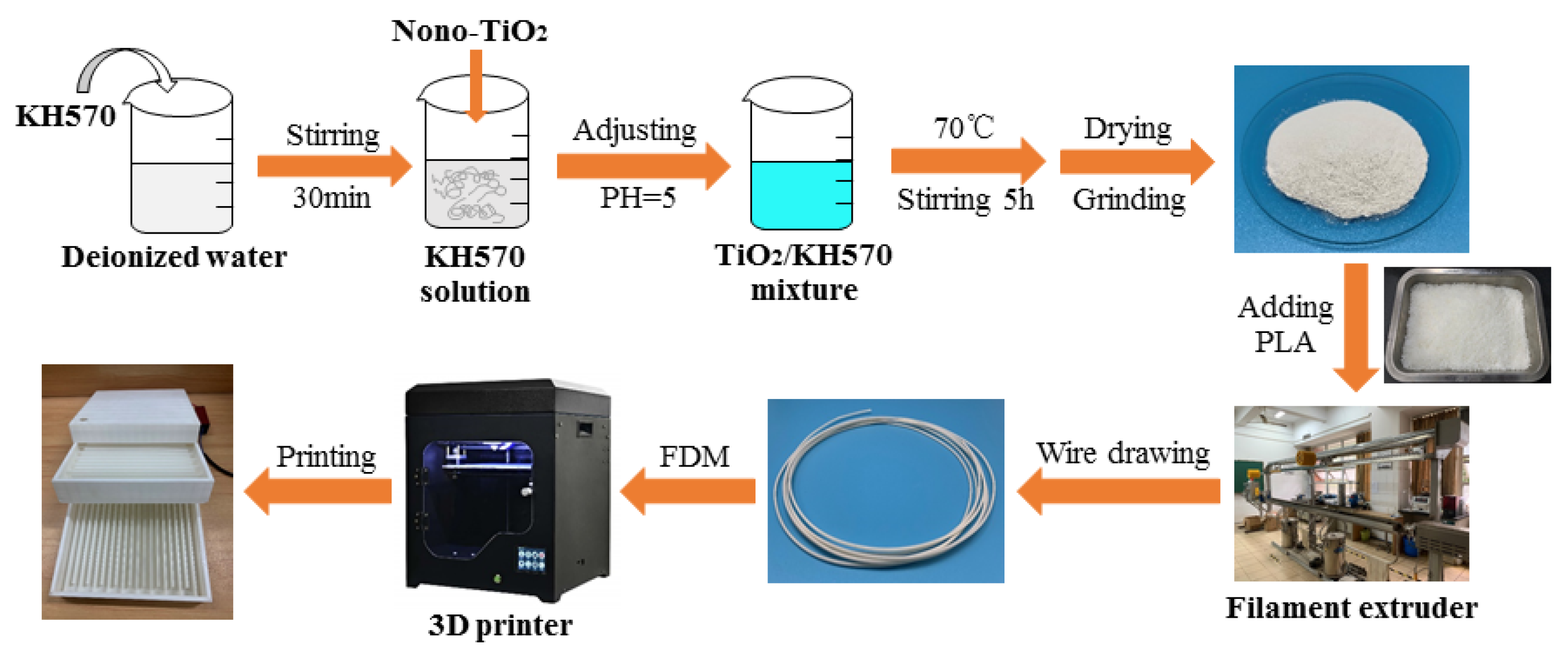
2.2.1. Preparation of Nano-TiO2 Modified by the Silane Coupling Agent
2.2.2. Preparation of TiO2(KH-570)/PLA Composites
2.2.3. Preparation of Silver-Loaded TiO2 Photocurable Coatings
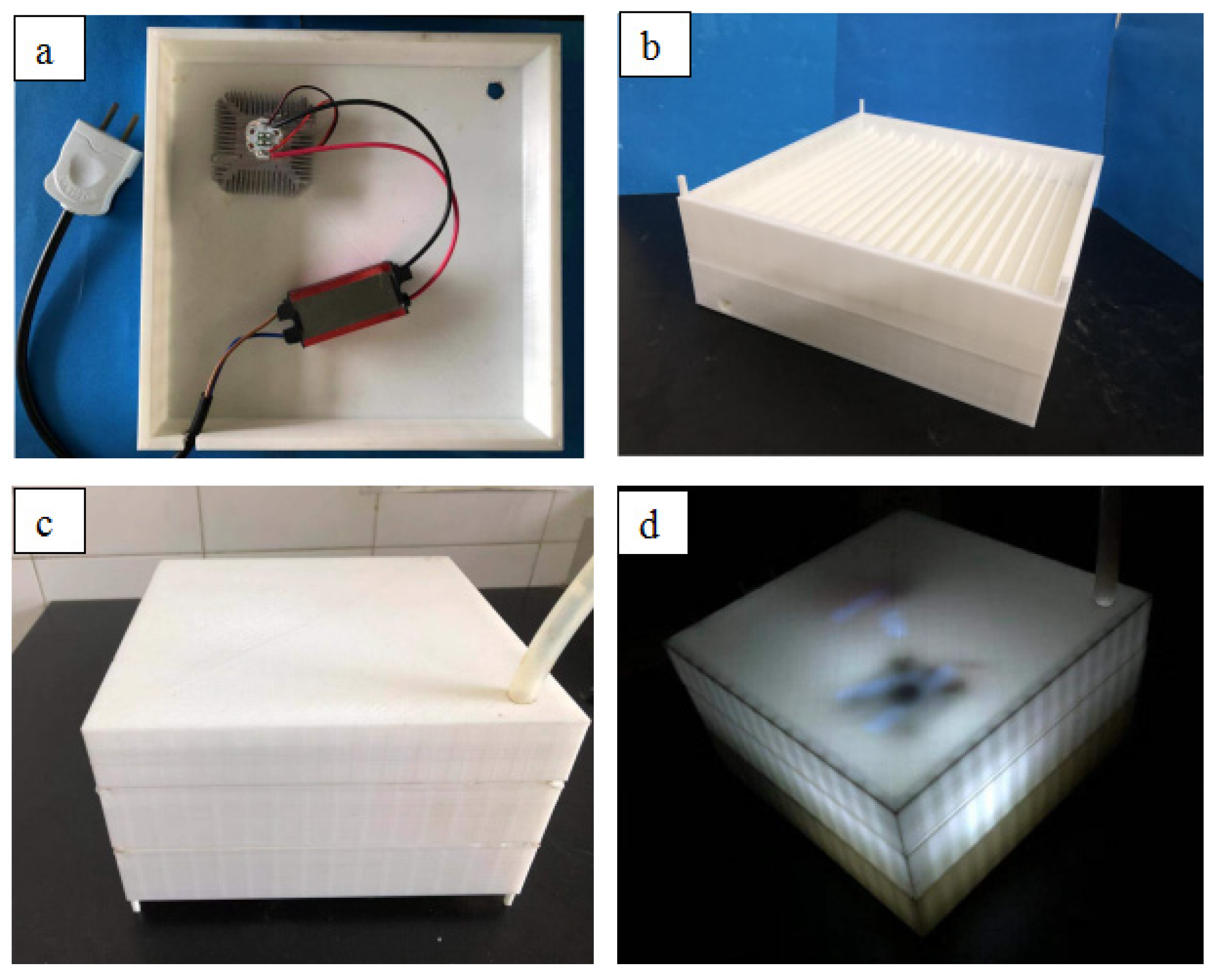
2.2.4. The 3D Printing Test
2.3. Characterization
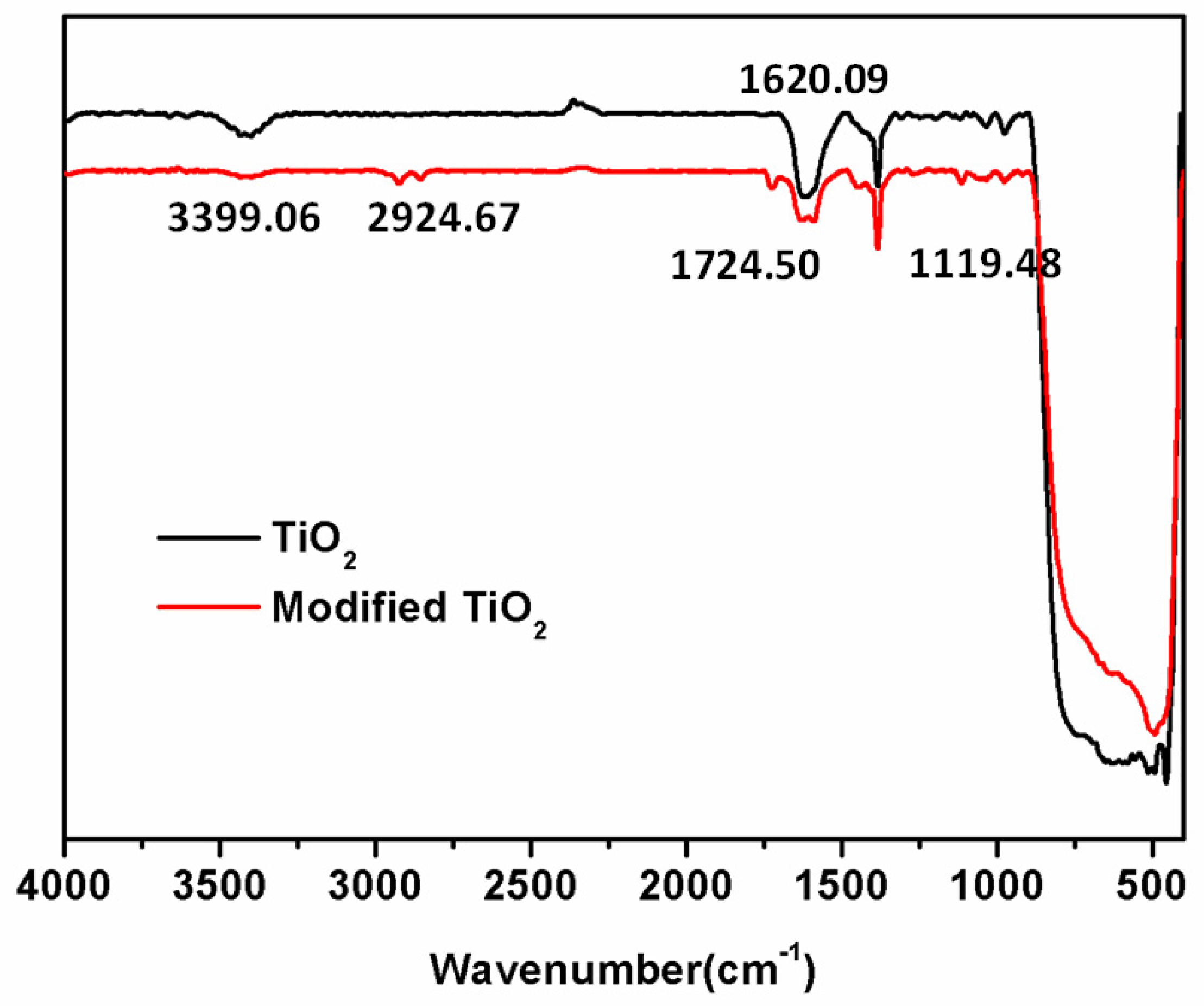
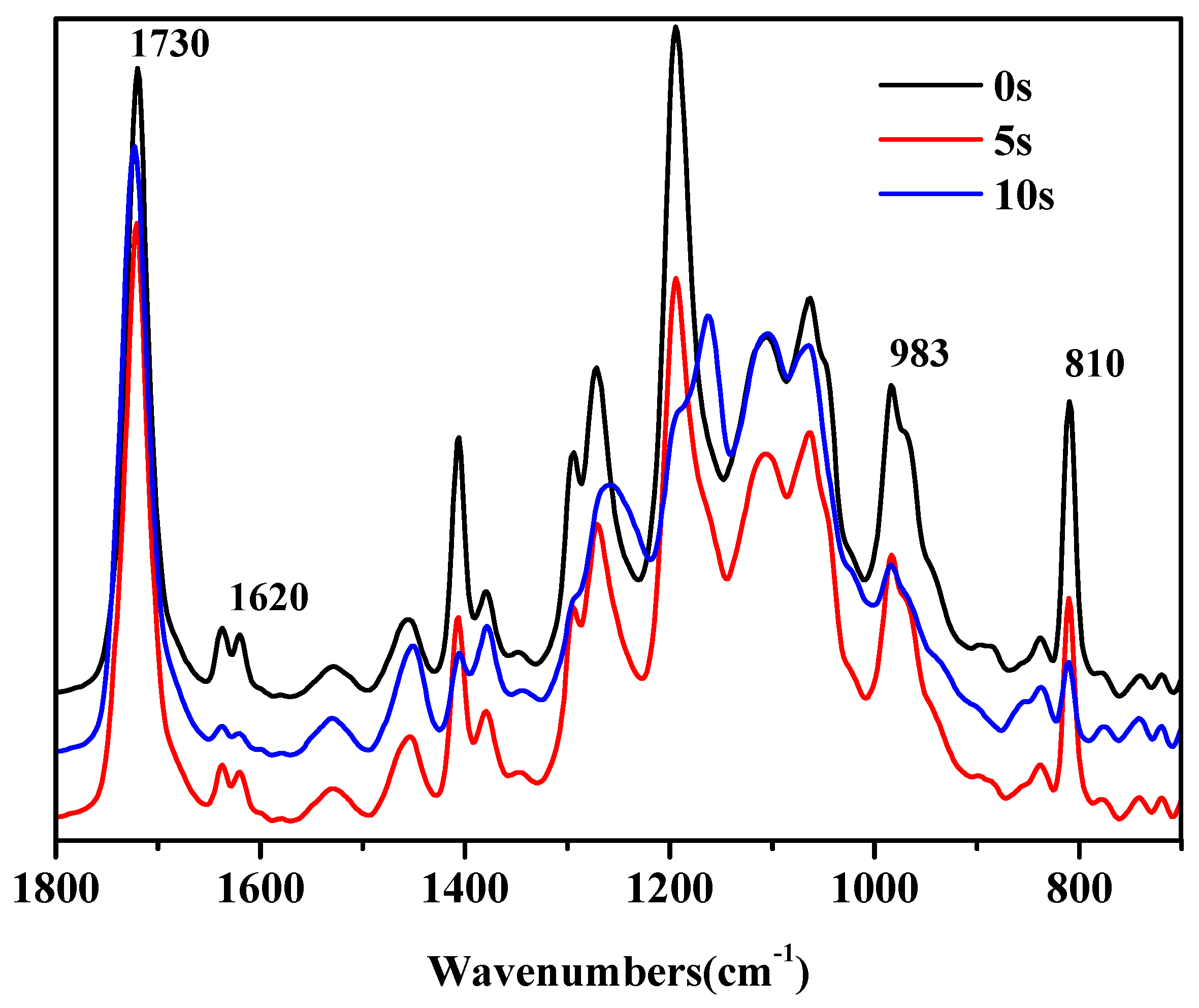
2.3.1. FTIR Analysis
2.3.2. SEM Analysis
2.3.3. TG Analysis
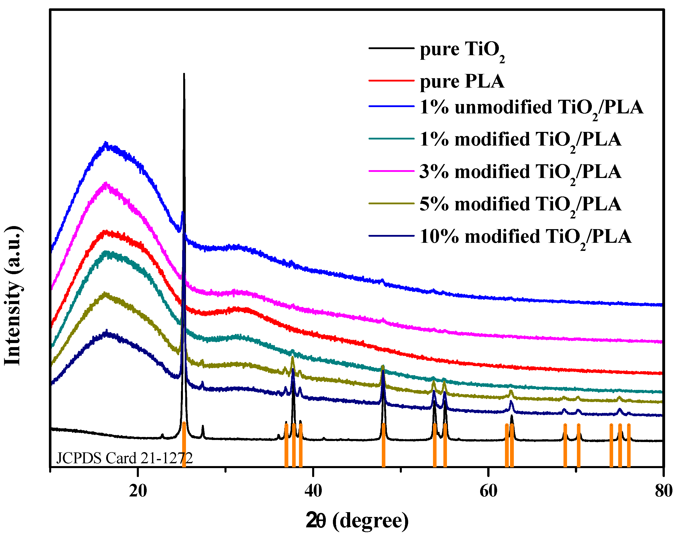
2.3.4. X-ray Analysis
2.3.5. Degradation Performance Test
2.3.6. Sterilization Performance Test
3. Results and Discussion
3.1. FTIR Analysis
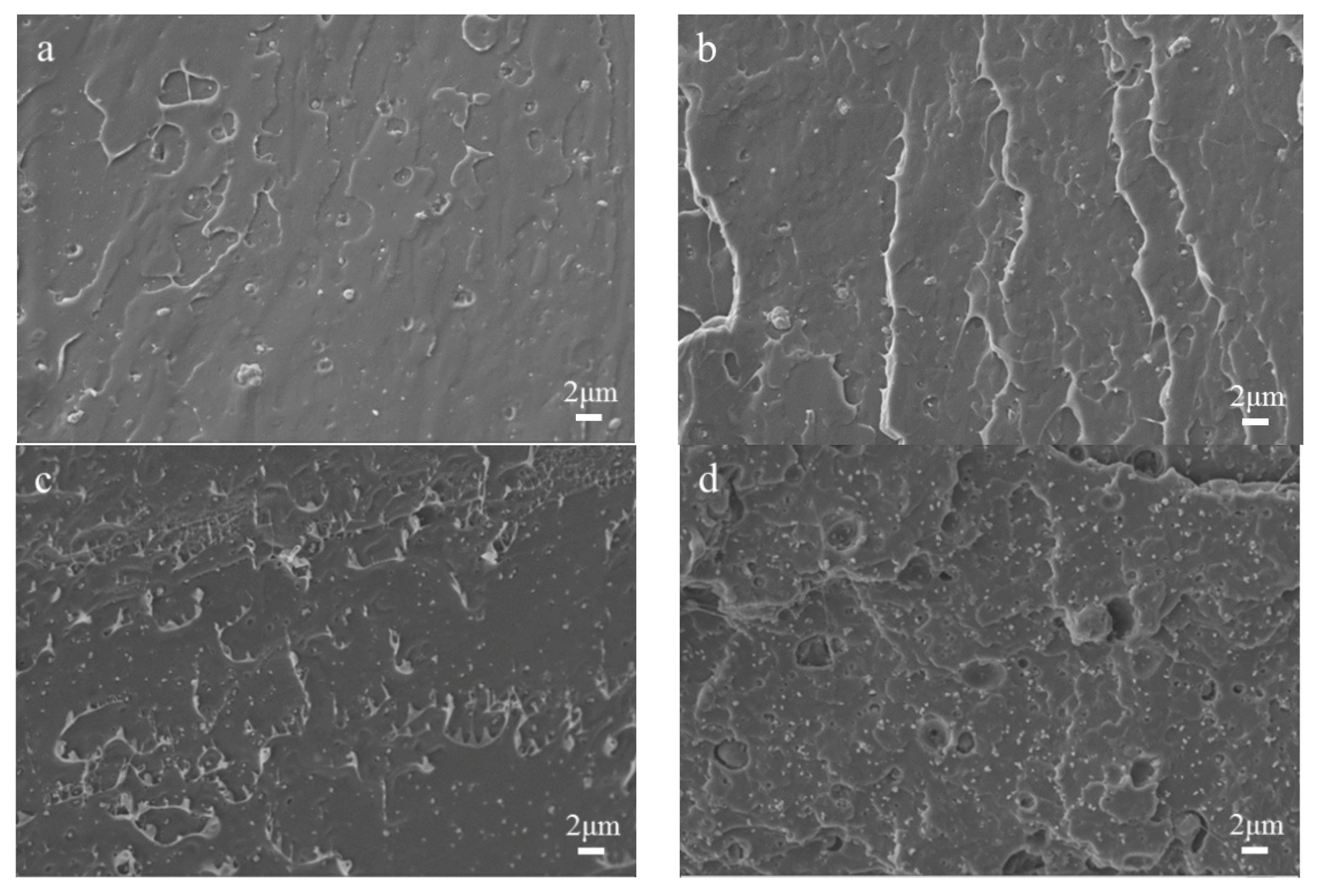
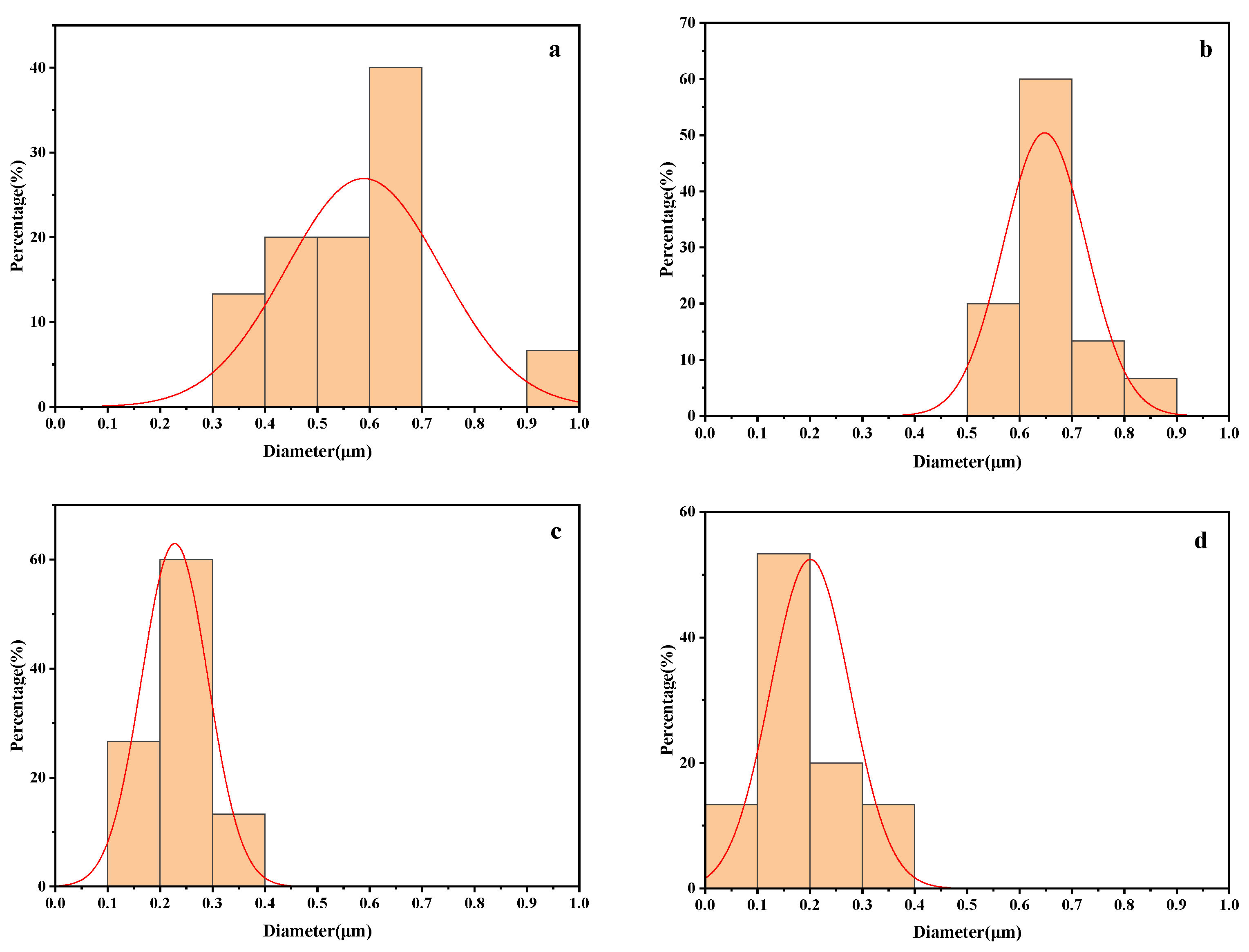
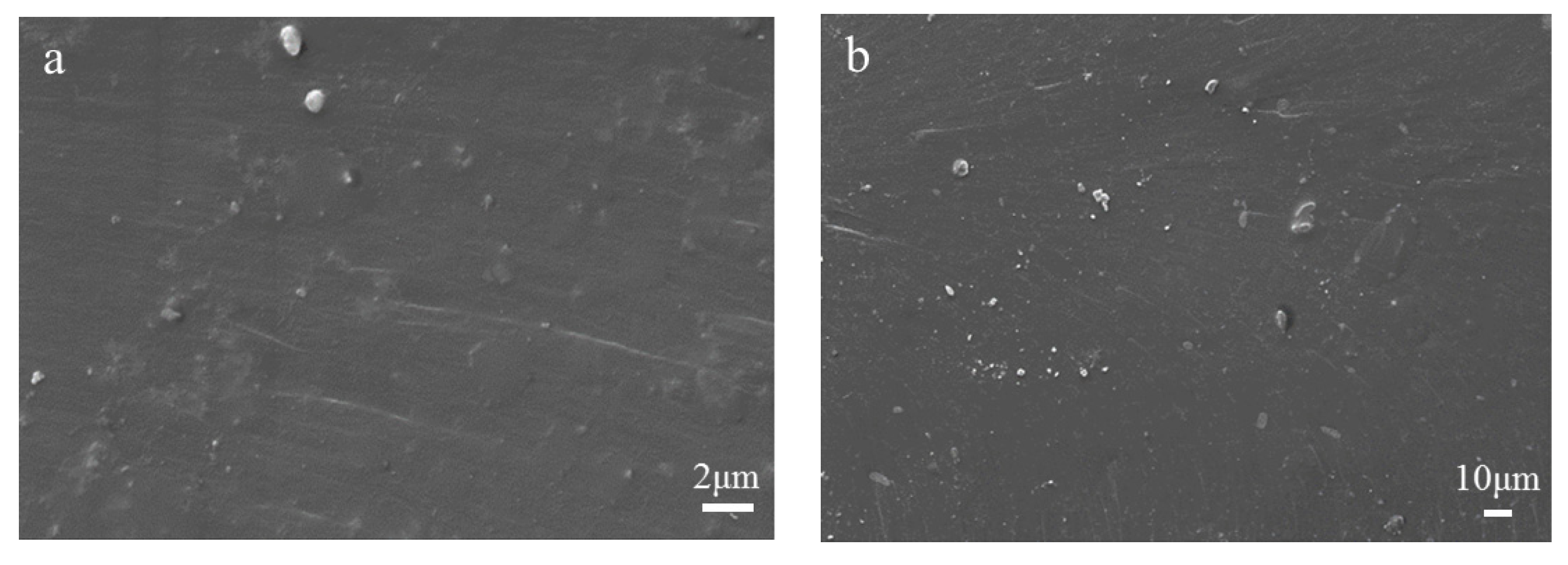
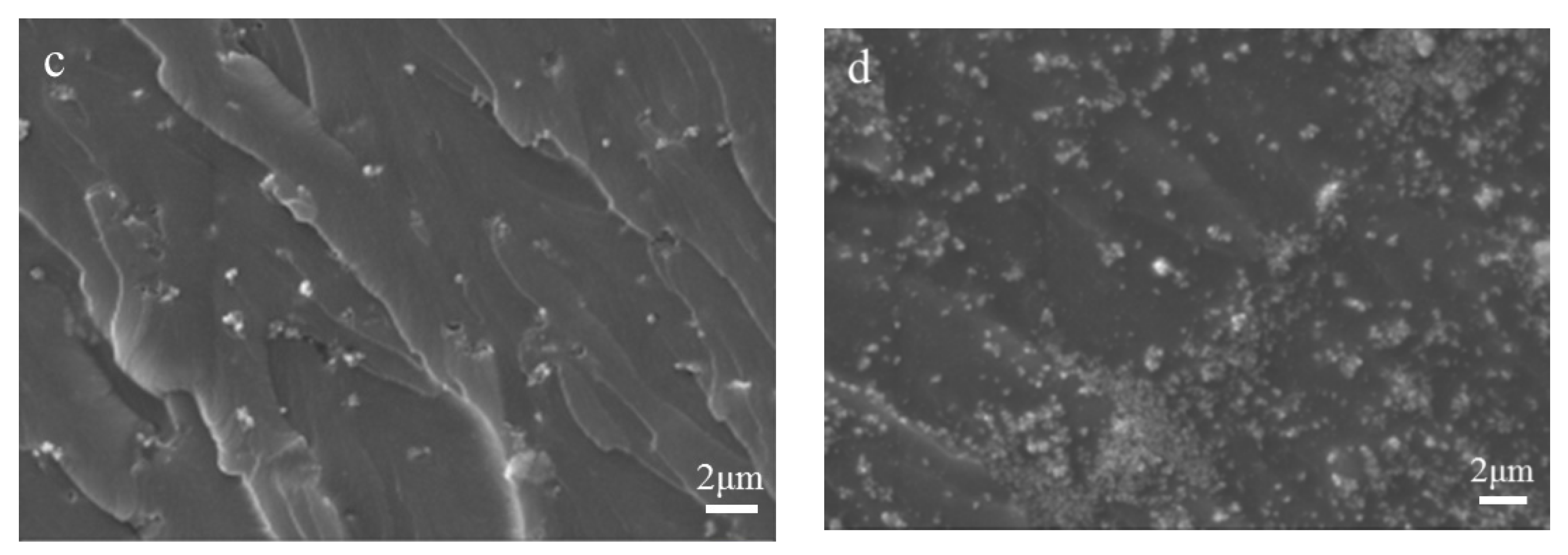
3.2. SEM Analysis
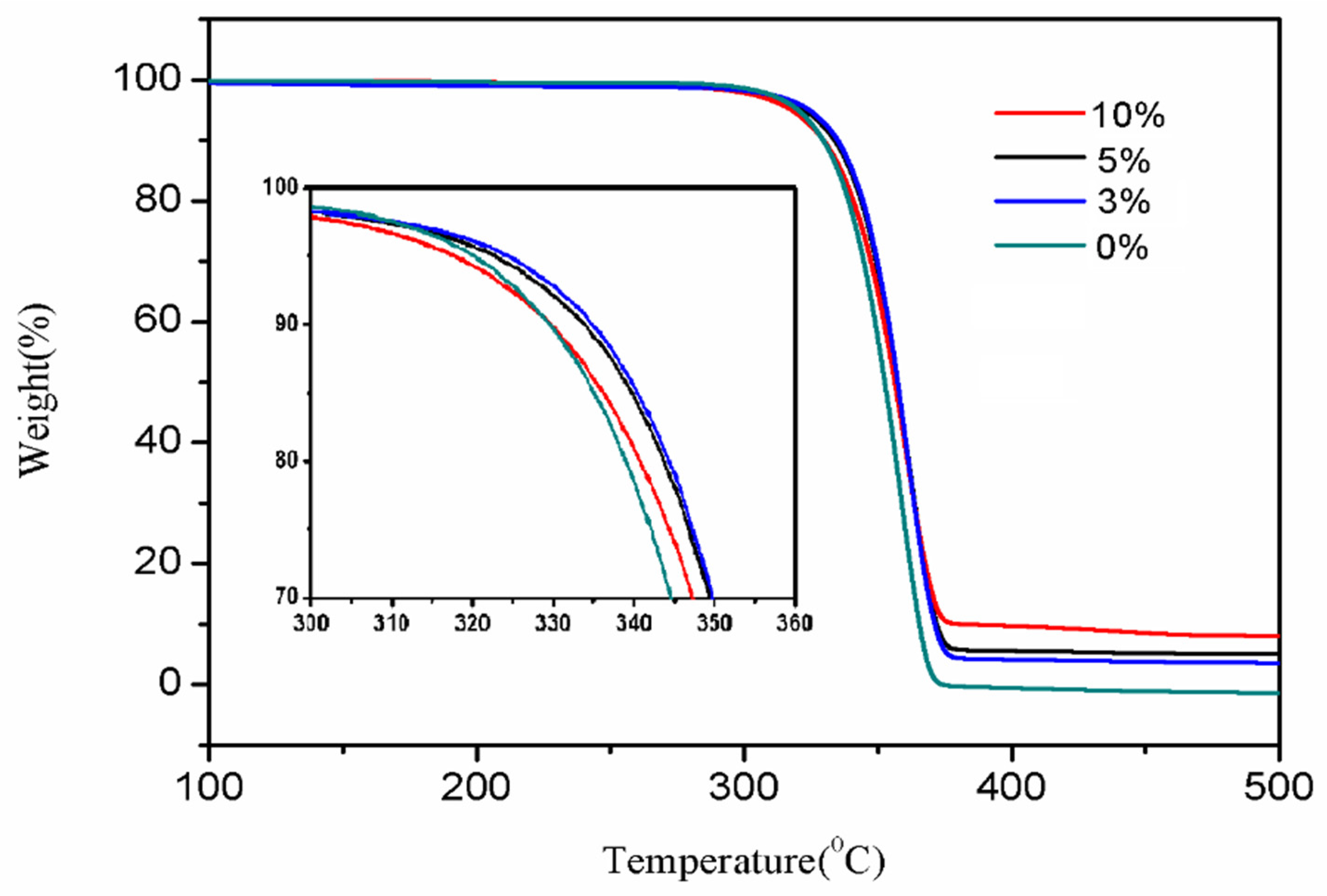
3.3. TG Analysis
3.4. X-ray Analysis
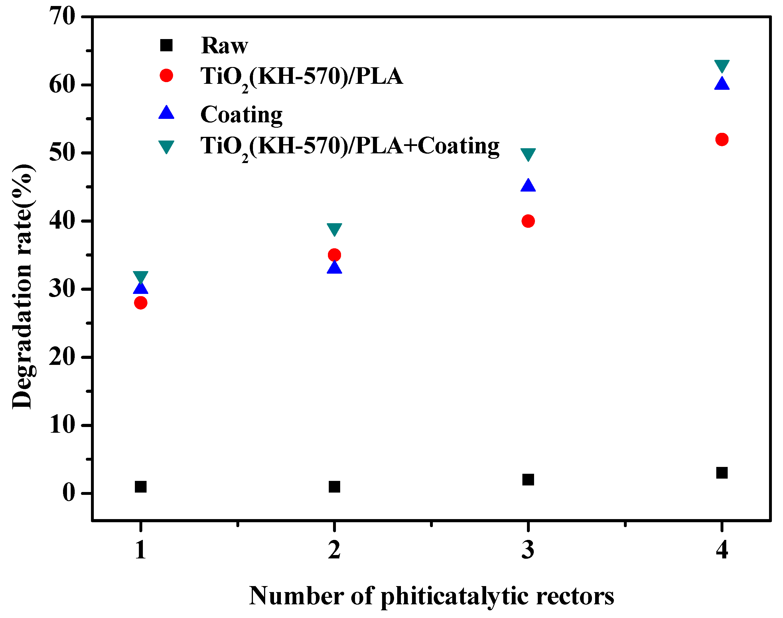
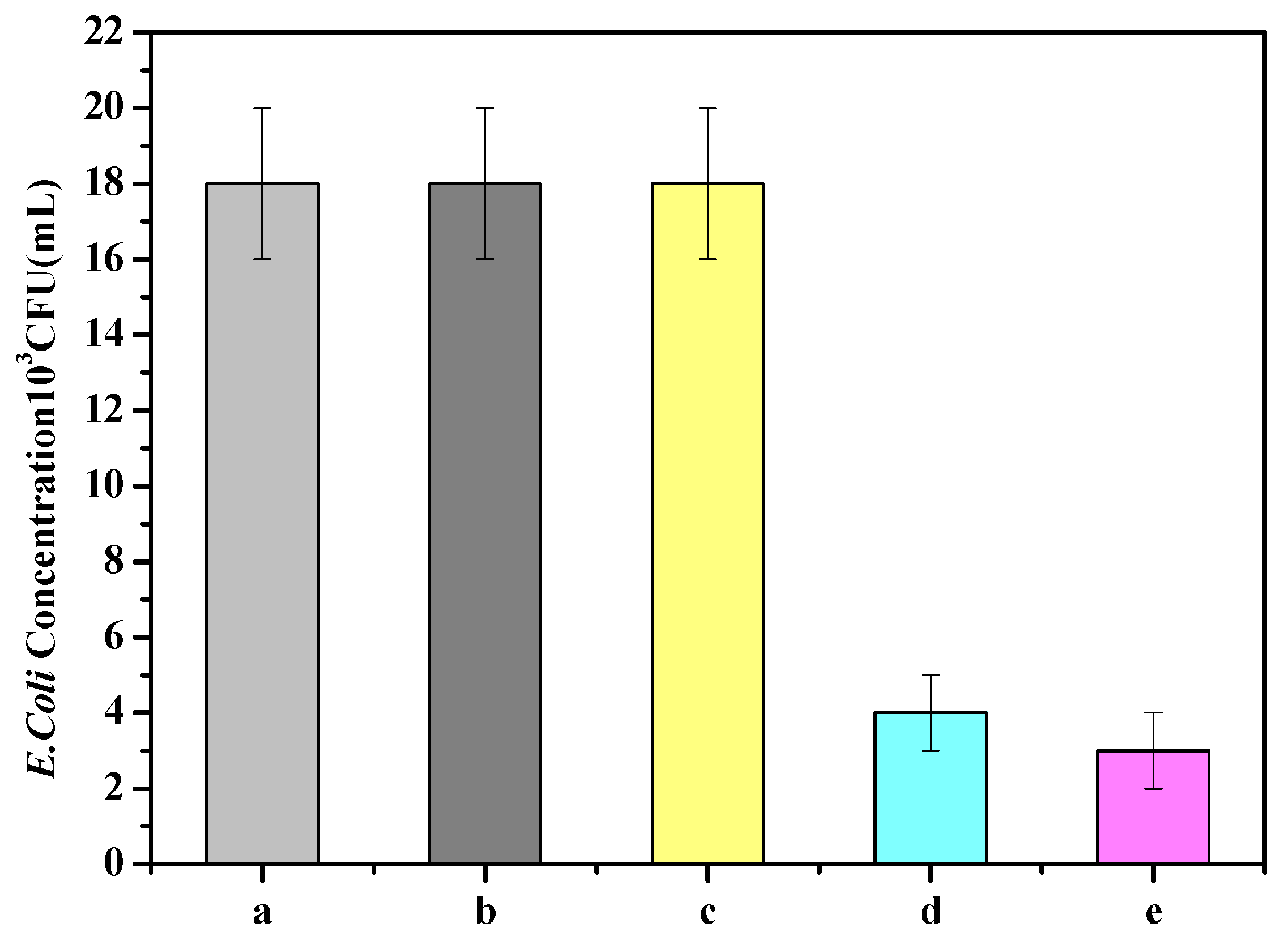
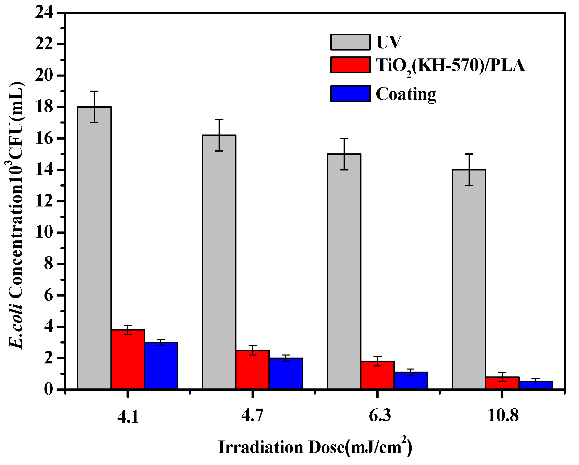
3.5. Printing Test and Degradation Performance Analysis of Water Treatment Equipment
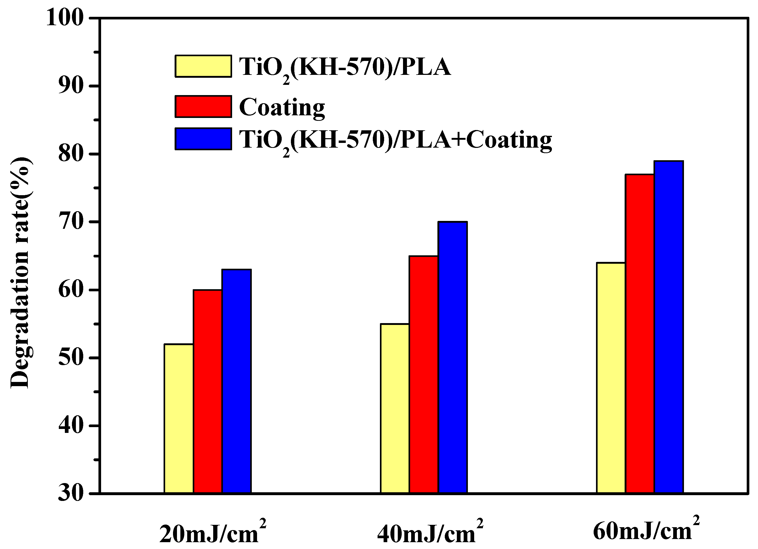
3.6. Printing Test and Degradation Performance Analysis of Water Treatment Equipment
4. Conclusions
Author Contributions
Funding
Institutional Review Board Statement
Informed Consent Statement
Data Availability Statement
Conflicts of Interest
References
- Shen, L.; Li, Y.; Zheng, J.; Lu, M.; Wu, K. Modified epoxy acrylate resin for photocurable temporary protective coatings. Prog. Org. Coat. 2015, 89, 17–25. [Google Scholar] [CrossRef]
- Wang, N.; Zheng, T.; Zhang, G.; Wang, P. A review on Fenton-like processes for organic wastewater treatment. J. Environ. Chem. Eng. 2016, 4, 762–787. [Google Scholar] [CrossRef] [Green Version]
- Michael-Kordatou, I.; Michael, C.; Duan, X.; He, X.; Dionysiou, D.D.; Mills, M.A.; Fatta-Kassinos, D. Dissolved effluent organic matter: Characteristics and potential implications in wastewater treatment and reuse applications. Water Res. 2015, 77, 213–248. [Google Scholar] [CrossRef] [PubMed]
- Maroušek, J.; Kolář, L.; Strunecký, O.; Kopecký, M.; Bartoš, P.; Maroušková, A.; Cudlínová, E.; Konvalina, P.; Šoch, M.; Moudrý, J., Jr.; et al. Modified biochars present an economic challenge to phosphate management in wastewater treatment plants. J. Clean. Prod. 2020, 272, 123015–123022. [Google Scholar] [CrossRef]
- Xiao, R.; Wei, Y.; An, D.; Li, D.; Ta, X.; Wu, Y.; Ren, Q. A review on the research status and development trend of equipment in water treatment processes of recirculating aquaculture systems. Rev. Aquacult. 2019, 11, 863–895. [Google Scholar] [CrossRef]
- Malik, O.A.; Hsu, A.; Johnson, L.A.; De Sherbinin, A. A global indicator of wastewater treatment to inform the Sustainable Development Goals (SDGs). Environ. Sci. Policy 2015, 48, 172–185. [Google Scholar] [CrossRef]
- Asghar, A.; Raman, A.A.A.; Daud, W.M.A.W. Advanced oxidation processes for in-situ production of hydrogen peroxide/hydroxyl radical for textile wastewater treatment: A review. J. Clean. Prod. 2015, 87, 826–838. [Google Scholar] [CrossRef] [Green Version]
- Pei, Y.; Tao, C.; Ling, Z.; Yu, Z.; Ji, J.; Khan, A.; Mamtimin, T.; Liu, P.; Li, X. Exploring novel Cr(VI) remediation genes for Cr(VI)-contaminated industrial wastewater treatment by comparative metatranscriptomics and metagenomics. Sci. Total Environ. 2020, 742, 140435–140447. [Google Scholar] [CrossRef] [PubMed]
- Gross, A.; Park, E. Water and wastewater treatment worldwide: The industry and the market for equipment and chemicals. Bus. Econ. 2018, 53, 37–47. [Google Scholar] [CrossRef]
- Wang, S.; Peng, Y. Natural zeolites as effective adsorbents in water and wastewater treatment. Chem. Eng. J. 2010, 156, 11–24. [Google Scholar] [CrossRef]
- Rokicka-Konieczna, P.; Markowska-Szczupak, A.; Kusiak-Nejman, E.; Morawski, A.W. Photocatalytic water disinfection under the artificial solar light by fructosemodified TiO2. Chem. Eng. J. 2019, 372, 203–215. [Google Scholar] [CrossRef]
- Yurdakal, S.; Tek, B.S.; Değirmenci, Ç.; Palmisano, G. Selective photocatalytic oxidation of aromatic alcohols in solar-irradiated aqueous suspensions of Pt, Au, Pd and Ag loaded TiO2 catalysts. Catal. Today 2017, 281, 53–59. [Google Scholar] [CrossRef]
- Birben, N.; Uyguner-Demirel, C.; Bekbolet, M. Photocatalytic Removal of Microbiological Consortium and Organic Matter in Greywater. Catalysts 2016, 6, 91. [Google Scholar] [CrossRef] [Green Version]
- Hajipour, P.; Bahrami, A.; Mehr, M.Y.; van Driel, W.D.; Zhang, K. Facile Synthesis of Ag Nanowire/TiO2 and Ag Nanowire/TiO2/GO Nanocomposites for Photocatalytic Degradation of Rhodamine B. Materials 2021, 14, 763. [Google Scholar] [CrossRef]
- Mamaghani, A.H.; Haghighat, F.; Lee, C. Photocatalytic oxidation technology for indoor environment air purification: The state-of-the-art. Appl. Catal. B Environ. 2017, 203, 247–269. [Google Scholar] [CrossRef]
- Xu, J.; Chen, Y.; Dong, Z.; Peng, Y.; Situ, Y.; Huang, H. Strong effect of multi-electron oxygen reduction reaction on photocatalysis through the promotion of interfacial charge transfer. Appl. Catal. B Environ. 2019, 252, 41–46. [Google Scholar] [CrossRef]
- Friedmann, D.; Mendive, C.; Bahnemann, D. TiO2 for water treatment: Parameters affecting the kinetics and mechanisms of photocatalysis. Appl. Catal. B Environ. 2010, 99, 398–406. [Google Scholar] [CrossRef]
- Sundar, K.P.; Kanmani, S. Progression of Photocatalytic reactors and it’s comparison: A Review. Chem. Eng. Res. Des. 2020, 154, 135–168. [Google Scholar] [CrossRef]
- Griffiths, C.A.; Howarth, J.; de Almeida-Rowbotham, G.; Rees, A.; Kerton, R. A design of experiments approach for the optimisation of energy and waste during the production of parts manufactured by 3D printing. J. Clean. Prod. 2016, 139, 74–114. [Google Scholar] [CrossRef] [Green Version]
- Wang, X.; Jiang, M.; Zhou, Z.; Gou, J.; Hui, D. 3D printing of polymer matrix composites: A review and prospective. Compos. Part B Eng. 2017, 110, 442–458. [Google Scholar] [CrossRef]
- Wang, S.; Ma, Y.; Deng, Z.; Zhang, S.; Cai, J. Effects of fused deposition modeling process parameters on tensile, dynamic mechanical properties of 3D printed polylactic acid materials. Polym. Test. 2020, 86, 106483–106490. [Google Scholar] [CrossRef]
- Balogun, H.A.; Sulaiman, R.; Marzouk, S.S.; Giwa, A.; Hasan, S.W. 3D printing and surface imprinting technologies for water treatment: A review. J. Water Process. Eng. 2019, 31, 100786–100801. [Google Scholar] [CrossRef]
- Martin-Somer, M.; Moreno-SanSegundo, J.; Alvarez-Fernandez, C.; van Grieken, R.; Marugan, J. High-performance low-cost solar collectors for water treatment fabricated with recycled materials, open-source hardware and 3d-printing technologies. Sci. Total Environ. 2021, 784, 147119–147128. [Google Scholar] [CrossRef] [PubMed]
- Hwa, L.C.; Uday, M.B.; Ahmad, N.; Noor, A.M.; Rajoo, S.; Zakaria, K.B. Integration and Fabrication of the Cheap Ceramic Membrane through 3D Printing Technology. Mater. Today Commun. 2018, 15, 134–156. [Google Scholar] [CrossRef]
- Liu, X.; Yang, Y.; Shi, X.; Li, K. Fast Photocatalytic Degradation of Methylene Blue Dye Using a Low-power Diode Laser. J. Hazard. Mater. 2015, 283, 267–302. [Google Scholar] [CrossRef] [PubMed]
- De Falco, G.; Porta, A.; Petrone, A.M.; del Gaudio, P.; el Hassanin, A.; Commodo, M.; Minutolo, P.; Squillace, A.; D’Anna, A. Antimicrobial activity of flame-synthesized nano-TiO2 coatings. Environ. Sci. Nano 2017, 4, 1095–1107. [Google Scholar] [CrossRef]
- Li, W.; Zhang, C.; Chi, H.; Li, L.; Lan, T.; Han, P.; Chen, H.; Qin, Y. Development of Antimicrobial Packaging Film Made from Poly(Lactic Acid) Incorporating Titanium Dioxide and Silver Nanoparticles. Molecules 2017, 22, 1170. [Google Scholar] [CrossRef] [PubMed] [Green Version]
- Yañez, D.; Guerrero, S.; Lieberwirth, I.; Ulloa, M.T.; Gomez, T.; Rabagliati, F.M.; Zapata, P.A. Photocatalytic inhibition of bacteria by TiO2 nanotubes-doped polyethylene composites. Appl. Catal. A Gen. 2015, 489, 255–261. [Google Scholar] [CrossRef]
- Gao, Z.; Sun, P.; Fang, Y.; Li, C.; Yuan, X.; Zheng, X.; Gao, J. Effect of heat treatment under vacuum on structure and visible-light photocatalytic activity of nanoTiO2. RSC Adv. 2019, 9, 32691–32698. [Google Scholar] [CrossRef] [Green Version]
- Chen, J.; Kou, S.; Poon, C. Hydration and properties of nano-TiO2 blended cement composites. Cem. Concr. Compos. 2012, 34, 642–649. [Google Scholar] [CrossRef]
- Li, F.; Liang, Z.; Zheng, X.; Zhao, W.; Wu, M.; Wang, Z. Toxicity of nano-TiO2 on algae and the site of reactive oxygen species production. Aquat. Toxicol. 2015, 158, 1–13. [Google Scholar] [CrossRef] [PubMed]
- Li, B.; Zhang, K.; Yang, W.; Yin, X.; Liu, Y. Enhanced corrosion resistance of HA/CaTiO3/TiO2/PLA coated AZ31 alloy. J. Taiwan Inst. Chem. E. 2016, 59, 465–473. [Google Scholar] [CrossRef]
- Deng, Y.; Li, J.; He, Z.; Hong, J.; Bao, J. Urethane acrylate-based photosensitive resin for threedimensional printing of stereolithographic elastomer. J. Appl. Polym. Sci. 2020, 137, 49294–49305. [Google Scholar] [CrossRef]
- Li, Y.; Chen, C.; Li, J.; Sun, X.S. Synthesis and characterization of bionanocomposites of poly(lactic acid) and TiO2 nanowires by in situ polymerization. Polymer 2011, 52, 2367–2375. [Google Scholar] [CrossRef]
- Luo, Y.; Wang, X.; Wang, Y. Effect of TiO2 nanoparticles on the long-term hydrolytic degradation behavior of PLA. Polym. Degrad. Stabil. 2012, 97, 721–728. [Google Scholar] [CrossRef]
- Cui, B.; Peng, H.; Xia, H.; Guo, X.; Guo, H. Magnetically recoverable core–shell nanocomposites c-Fe2O3@SiO2@TiO2–Ag with enhanced photocatalytic activity and antibacterial activity. Sep. Purif. Technol. 2013, 103, 251–257. [Google Scholar] [CrossRef]
- Athanasoulia, I.; Mikropoulou, M.; Karapati, S.; Tarantili, P.; Trapalis, C. Study of thermomechanical and antibacterial properties of TiO2/Poly(lactic acid) nanocomposites. Mater. Today Proc. 2018, 5, 27553–27562. [Google Scholar] [CrossRef]
- Valeš, V.; Buljan, M.; Janicki, V.; Bernstorff, S.; Mangold, S.; Siketić, Z.; Schneeweiss, O.; Holý, V. Fe2O3/TiO2 nanoparticles—a complex structural study. Thin Solid Films 2014, 564, 65–72. [Google Scholar] [CrossRef]
- Kumar, M.; Kumar, A. Performance assessment and degradation analysis of solar photovoltaictechnologies: A review. Renew. Sustain. Energ. Rev. 2017, 78, 554–587. [Google Scholar] [CrossRef]
- Zou, L.; Wang, H.; Jiang, X.; Yuan, G.; Wang, X. Enhanced photocatalytic efficiency in degrading organic dyes by coupling CdS nanowires with ZnFe2O4 nanoparticles. Sol. Energy 2020, 195, 271–277. [Google Scholar] [CrossRef]
- Fonseca, C.; Ochoa, A.; Ulloa, M.T.; Alvarez, E.; Canales, D.; Zapata, P.A. Poly(lactic acid)/TiO2 nanocomposites as alternative biocidal and ntifungal materials. Mater. Sci. Eng. C Mater. Biol. Appl. 2015, 57, 314–320. [Google Scholar] [CrossRef] [PubMed]
- Pormohammad, A.; Turner, R.J. Silver Antibacterial Synergism Activities with Eight Other Metal(loid)-Based Antimicrobials against Escherichia coli, Pseudomonas aeruginosa, and Staphylococcus aureus. Antibiotics 2020, 9, 853. [Google Scholar] [CrossRef] [PubMed]
- Xu, L.; Shi, X.; Qian, Q.; Bai, X.; Xu, L.; Wang, Q. Hydrothermal sterilization in silver nitrate solution endows plasma sprayed hydroxyapatite coating with antibacterial property. Mater. Lett. 2020, 263, 127258–127261. [Google Scholar] [CrossRef]


| Parameter | Set Value |
|---|---|
| Filament diameter | 1.75 mm |
| Nozzle temperature | 180–220 °C |
| Nozzle diameter | 0.4 |
| Fill density | 100% |
| Printing speed | 25–50 mm/s |
| Single-layer printing thickness | 0.1–0.3 mm |
| Bed temperature | 40–70 °C |
| Sample | T0/°C | Tf/°C | ΔT0/°C | ΔTf/°C |
|---|---|---|---|---|
| PLA | 337.0 | 368.7 | ||
| 3% TiO2(KH-570)/PLA | 337.8 | 371.8 | 0.8 | 3.1 |
| 5% TiO2(KH-570)/PLA | 341.2 | 371.9 | 4.2 | 3.2 |
| 10% TiO2(KH-570)/PLA | 342.3 | 371.8 | 5.3 | 3.1 |
Publisher’s Note: MDPI stays neutral with regard to jurisdictional claims in published maps and institutional affiliations. |
© 2021 by the authors. Licensee MDPI, Basel, Switzerland. This article is an open access article distributed under the terms and conditions of the Creative Commons Attribution (CC BY) license (https://creativecommons.org/licenses/by/4.0/).
Share and Cite
Mai, Z.; Liu, D.; Chen, Z.; Lin, D.; Zheng, W.; Dong, X.; Gao, Q.; Zhou, W. Fabrication and Application of Photocatalytic Composites and Water Treatment Facility Based on 3D Printing Technology. Polymers 2021, 13, 2196. https://0-doi-org.brum.beds.ac.uk/10.3390/polym13132196
Mai Z, Liu D, Chen Z, Lin D, Zheng W, Dong X, Gao Q, Zhou W. Fabrication and Application of Photocatalytic Composites and Water Treatment Facility Based on 3D Printing Technology. Polymers. 2021; 13(13):2196. https://0-doi-org.brum.beds.ac.uk/10.3390/polym13132196
Chicago/Turabian StyleMai, Zhirui, Di Liu, Ziyao Chen, Dongsong Lin, Wenxu Zheng, Xianming Dong, Qiongzhi Gao, and Wuyi Zhou. 2021. "Fabrication and Application of Photocatalytic Composites and Water Treatment Facility Based on 3D Printing Technology" Polymers 13, no. 13: 2196. https://0-doi-org.brum.beds.ac.uk/10.3390/polym13132196