Article

Plasticized Sodium-Ion Conducting PVA Based Polymer Electrolyte for Electrochemical Energy Storage—EEC Modeling, Transport Properties, and Charge-Discharge Characteristics

by
Shujahadeen B. Aziz
1,2,*,
Muaffaq M. Nofal
3,
Rebar T. Abdulwahid
1,4,
Hewa O. Ghareeb
5,
Elham M. A. Dannoun
6,
Ranjdar M. Abdullah
1,
M. H. Hamsan
7 and
M. F. Z. Kadir
7
1
Hameed Majid Advanced Polymeric Materials Research Lab., Physics Department, College of Science, University of Sulaimani, Qlyasan Street, Sulaimani 46001, Iraq
2
Department of Civil Engineering, College of Engineering, Komar University of Science and Technology, Sulaimani 46001, Iraq
3
Department of Mathematics and General Sciences, Prince Sultan University, P.O. Box 66833, Riyadh 11586, Saudi Arabia
4
Department of Physics, College of Education, University of Sulaimani, Old Campus, Sulaimani 46001, Iraq
5
Chemistry Department, College of Science, University of Sulaimani, Qlyasan Street, Sulaimani 46001, Iraq
6
Associate Director of General Science Department, Woman Campus, Prince Sultan University, P.O. Box 66833, Riyadh 11586, Saudi Arabia
7
Centre for Foundation Studies in Science, University of Malaya, Kuala Lumpur 50603, Malaysia
*
Author to whom correspondence should be addressed.
Submission received: 31 January 2021 / Revised: 25 February 2021 / Accepted: 28 February 2021 / Published: 5 March 2021

Abstract

:
This report presents the preparation of plasticized sodium ion-conducting polymer electrolytes based on polyvinyl alcohol (PVA)via solution cast technique. The prepared plasticized polymer electrolytes were utilized in the device fabrication of electrical double-layer capacitors (EDLCs). On an assembly EDLC system, cyclic voltammetry (CV), electrical impedance spectroscopy (EIS), linear sweep voltammetry (LSV), transfer number measurement (TNM) and charge–discharging responses were performed. The influence of plasticization on polymer electrolytes was investigated in terms of electrochemical properties applying EIS and TNM. The EIS was fitted with electrical equivalent circuit (EEC) models and ion transport parameters were estimated with the highest conductivity of 1.17 × 10⁻³ S cm−1 was recorded. The CV and charge-discharging responses were used to evaluate the capacitance and the equivalent series resistance (ESR), respectively. The ESR of the highest conductive sample was found to be 91.2 Ω at the first cycle, with the decomposition voltage of 2.12 V. The TNM measurement has shown the dominancy of ions with tion = 0.982 for the highest conducting sample. The absence of redox peaks was proved via CV, indicating the charge storing process that comprised ion accumulation at the interfacial region. The fabricated EDLC device is stable for up to 400 cycles. At the first cycle, a high specific capacitance of 169 F/g, an energy density of 19 Wh/kg, and a power density of 600 W/kg were obtained.

Graphical Abstract

1. Introduction

The modern lifestyle has required wide scale consumption of fossil fuels widely, causing massive environmental pollution. This has urged us to look for alternatives that are characterized by renewability and sustainability. Herein, several different types, such as wind, fuel cells, solar cells, geothermal and biofuels, have been considered to replace fossil fuels in industries [1,2]. The conventional organic sol-gel electrolytes have recently been replaced by new impressive electrolyte materials known as solid polymer electrolytes (SPEs). These electrolytes have many advantages such as being harmless, the ease of processability and chemical, electrochemical and dimensional stabilities [3,4].
The polar polymers being ionically conductive incorporated with additives, for instance, metal salts, are less well-studied in electrochemical devices, especially lithium batteries, compared to other electrochemical devices [5,6]. Polar polymers can dissolve both inorganic and transition metal salts since a strong interaction occurs between the unshared pair electron of the heteroatom; nitrogen or oxygen of the polymer on one side and cation of the dopant salt on the other side.
Natural polymers are candidates of choice in preparing solid biopolymer electrolytes [7,8,9,10,11]. Herein, polyvinyl alcohol (PVA), as one of the natural polymers, is benign and contains polar oxygen atoms from the vinyl alcohol groups. This enables this polymer to make complexation between the polar group and cations, forming a polymer electrolyte blend [12,13]. Several properties of the blended polymer electrolyte, for instance, chemical stability, quite large dielectric strength, satisfactory charge-storage capacity (CSC), dopant dependence of electric, abrasion resistance and optical characteristics, have drawn the attention of many researchers to focus on it [14]. Developing benign electrolytes is one of the goals that all researchers have taken into consideration in the field of secondary lithium batteries. Nowadays, among many other new classes of useful materials, SPEs are still one of the hottest topics that many research groups have focused on [15].
The modification of SPEs is addressed to be eligible for applications in lithium batteries and other electrochemical devices [16]. The commercialization of SPEs has faced two main barriers, which are low ionic conductivity and insufficient mechanical property [17].
It has previously been emphasized that glycerol as a chemical plasticizer improves the ionic conductivity of polymer-based electrolytes and enhances salt dissociation [18]. The latter has resulted from columbic force weakening between cations and anions of the salt; thereby, ion concentration increases. Chai and Isa [19] confirmed the influence of glycerol addition on ionic conductivity improvement and the mechanical strength increasing of a particular electrolyte film. Figure 1 shows that glycerol contains multi-hydroxyl moiety (-OH) in the structure that facilitates free ion movement in the polymer electrolytes (PE). Mattos et al. [20] also documented the conductivity improvement of electrolyte systems in this range (10−7 S cm−1–10−5 S cm−1) due to adding glycerol.
An electrical double-layer capacitor (EDLC) is a supercapacitor device (SCDs), which is characterized by the simplicity of fabrication and it has been widely studied [21,22]. Moreover, the increasing demand for wearable electronics and flexible EDLC further encouraged research groups to modify various components of the device [23,24]. Among different components of the device, a particular attention is given to the electrolyte of the EDLC. Many studies have shown that polymer based electrolyte can be considered a suitable candidate for the fabrication of flexible EDLC with good performance under bending, twisting and folding conditions [24,25,26,27]. Regarding electrode fabrication to be utilized in EDLCs, various carbon allotropies with relatively high surface areas (porous materials) and enough electrical conductivity can be used. These materials with these characteristics can encompass a considerable quantity of charged ions via adsorption and desorption processes [28,29]. Several crucial properties, such as equivalent series resistance (ESR), specific capacitance (Cs) and power (Pd), and energy (Ed) densities, must be taken into consideration in order to evaluate the efficiency and the performance of EDLCs. The two important terms Ed and Pd of energy devices generally refer to the amount of energy available and the energy delivery rate, respectively; which is usually expressed in the well-known Ragone plot [30,31]. EDLCs have extensively been applied to large-scale communication apparatuses, electronic technologies and hybrid automobiles [32,33]. Therefore, the efficiency and performance of EDLCs have to be modified via the usage of several materials such as activated carbon aerogels, graphene, carbon nanofibers and SPEs. These materials possess sufficient mechanical strength and electrochemical capacitance. Thus, the physiochemical properties of polymer electrolyte based EDLC should be carefully tuned and optimized in order to reach the industrial level, which is crucial from both practical and scientific viewpoints [34,35].
The most popular and usable carbon material is activated carbon (AC), a relatively perfect active material for electrode fabrication in EDLCs. This carbon material is characterized by a large surface area (usually 2500 m2/g), high conductivity and cost-efficiency [36,37]. Besides, carbon black (CB) is highly utilized as conducting material for fabricating the electrodes. It acts as a support filler. This material has a surface estimated to be in the range of 25 to 1500 m2/g, which is lower than AC [38].
The widespread use of electronic devices and all the related electronic wastes have resulted in climate change and negatively impacted on the environment. This urged the scientific community to devote large effort to overcome these issues and minimize livelihood implications and reduce the global worming effect using engineered biodegradable materials. This work is aiming at controlling various properties of biodegradable polymer electrolyte, so that an environmental friendly material for energy devices such as EDLC is viable. In this work, the eligibility of PVA:NaI:glycerol polymer electrolyte for EDLC device is addressed. Earlier studies highlighted that salts accompanying with low lattice energy should be considered for polymer electrolyte preparation. The selection of NaI (675 KJ/mole) over NaCl (796 KJ/mol), NaNO3 (755 KJ/mol), and NaOH (887 KJ/mol) is interrelated to the low lattice energy of NaI. Therefore, massive quantities of NaI can certainly be dissolved in host PVA polymer. Enormous amount of salt harvests additional charge carrier density, which is decisive to increase the DC conductivity value. Herein, the addition of a 50 wt.% of NaI salt has been applied to the PVA with different glycerol concentrations to obtain sodium ion-conducting plasticized electrolytes. Electrical impedance spectroscopy (EIS) was used to calculate ionic conductivity of PVA:NaI:glycerol-based polymer electrolyte at room temperature (RT). The dielectric properties of the prepared electrolytes were also intensively explained. The relatively high conducting electrolyte is employed in the EDLC assembly and tested its performance.

2. Experimental

2.1. Material and Preparation of SPE Plasticized Films

The main raw material used was PVA with an average molecular mass of 35,000 g/mol, purchased from Sigma Aldrich. Sodium iodide (NaI) salt was used to provide Na+ ions in the plasticized polymer electrolyte. In the preparation of plasticized polymer electrolytes, 1 g of PVA was putin 20 mL of distilled water and dissolved at 80 °C. Then, the mixture was left to reach the ambient temperature. A solution of 50 wt.% of NaI dopant was added to the polymer solution and stirred steadily until a clear solution was obtained. A series of 10 to 50 wt.% of glycerol plasticizer was then added separately to the PVA:NaI electrolyte. Ultimately, the solution mixtures were poured into a series of clean and dry clean glass Petri dishes to produce films. Afterward, the films were left to dry gradually at an ambient temperature to gain PVA:NaI:glycerol electrolyte films. Table 1 summarizes the weight ratio of samples.

2.2. Electrochemical Impedance Spectroscopy (EIS)

For the plasticized electrolytes’ impedance characterization, electrical impedance spectroscopy (EIS) was used in the evaluation using HIOKI 3532-50 LCR HiTESTER (50 Hz ≤ f ≤ 1000 kHz) at RT. The process of EIS measurements were comprised of putting the film between two stainless steel discs. From these measurements, both ionic conductivity and dielectric behaviors of the electrolytes were determined.

2.3. Transference Number Measurement (TNM)

For Transference Number Measurement (TNM) measurements, the polarization of stainless steel (SS) | conducting SPE | (SS) cell by fixing the working voltage at 0.80 V was implemented, and both ion (tion) as well as electron (tel) transference numbers (TNM) were obtained. For these measurements, V&A Instrument DP3003 digital DC source was used at RT. The tion can be determined from [12]:
t i o n = I i I s s I i
t e l = 1 t i o n ,
where the initial and steady-state currents are designated as Ii and Iss, respectively.

2.4. Linear Sweep Voltammetry (LSV)

The Linear Sweep Voltammetry (LSV) is informative and used to establish the potential stability of the PE. Digi-IVY DY2300 potentiostat was employed, and the sweep voltage range was determined at a sweep rate of 50 mV/s.

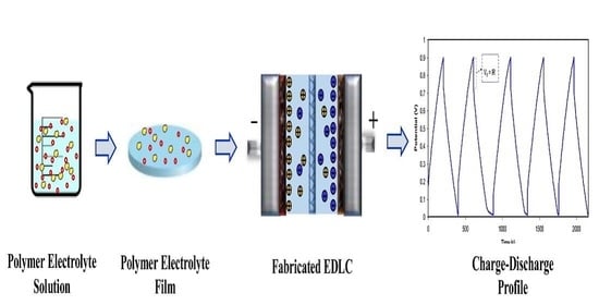
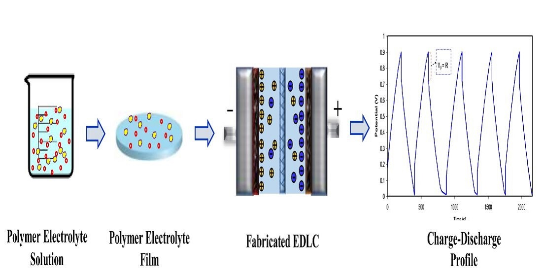
2.5. Fabrication of EDLC

A homogeneous mixture of 81.25% activated carbon (AC) and 6.25% carbon black (CB) was obtained by grinding using a planetary ball miller. Meanwhile, a homogeneous solution of 12.5% of polyvinylidene fluoride (PVdF) and 15 mL of N-methyl pyrrolidone (NMP) was obtained by stirring. This solution was added to the prepared powder and then poured into the PVdF-NMP solution. A thick black solution mixture from continuous stirring was obtained. The resulting mixture was coated on an aluminum foil through a doctor blade and dried in an oven at 60 °C. The created electrodes were stored in a desiccators to remove moisture. The EDLC assembly consisted of two electrodes with a surface area (2.01 cm2) and the conducting electrolyte. In the CR2032 coil, the cell was packed in a Teflon case.

2.6. Characterization of the EDLC

The CV experiment was run at different scan rates from (10 to 100) mV/s to investigate the scan rate impact on the specific capacitance (CCV), and the equation used to calculate CCV is represented by [21,30,31]:
C C V = V i V f I V d V 2 m v V f V i ,
where Vi and Vf are 0 V and 0.9 V, respectively, and I(V)dV is the CV response area obtained for the integration function of Origin 9.0 software. The v and m are the scan rate and mass of active material, respectively. 0.5 mA/cm2 as a constant current density is applied to the EDLC. To obtain the decisive parameters of EDLC; specific capacitance from the CV and charge–discharge (CCD), ESR, Ed, and Pd are determined using these expressions shown below [21,30,31]:
C C D = i s m
E S R = V d i
E = C s V 2 2
P = V 2 4 m ( E S R ) ,
where s and i are a gradient of the discharge region and applied current, respectively; Vd and V are the drop potential and applied voltage, respectively.

3. Results and Discussion

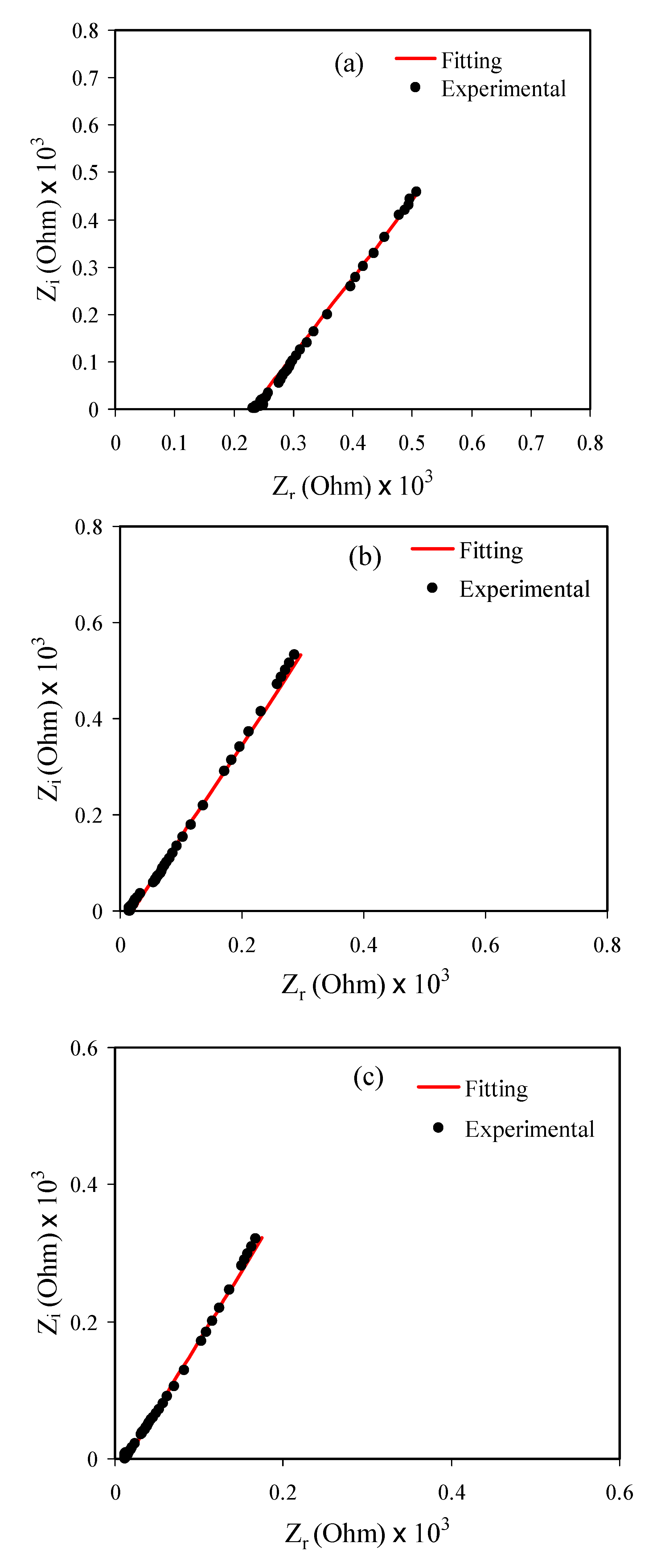
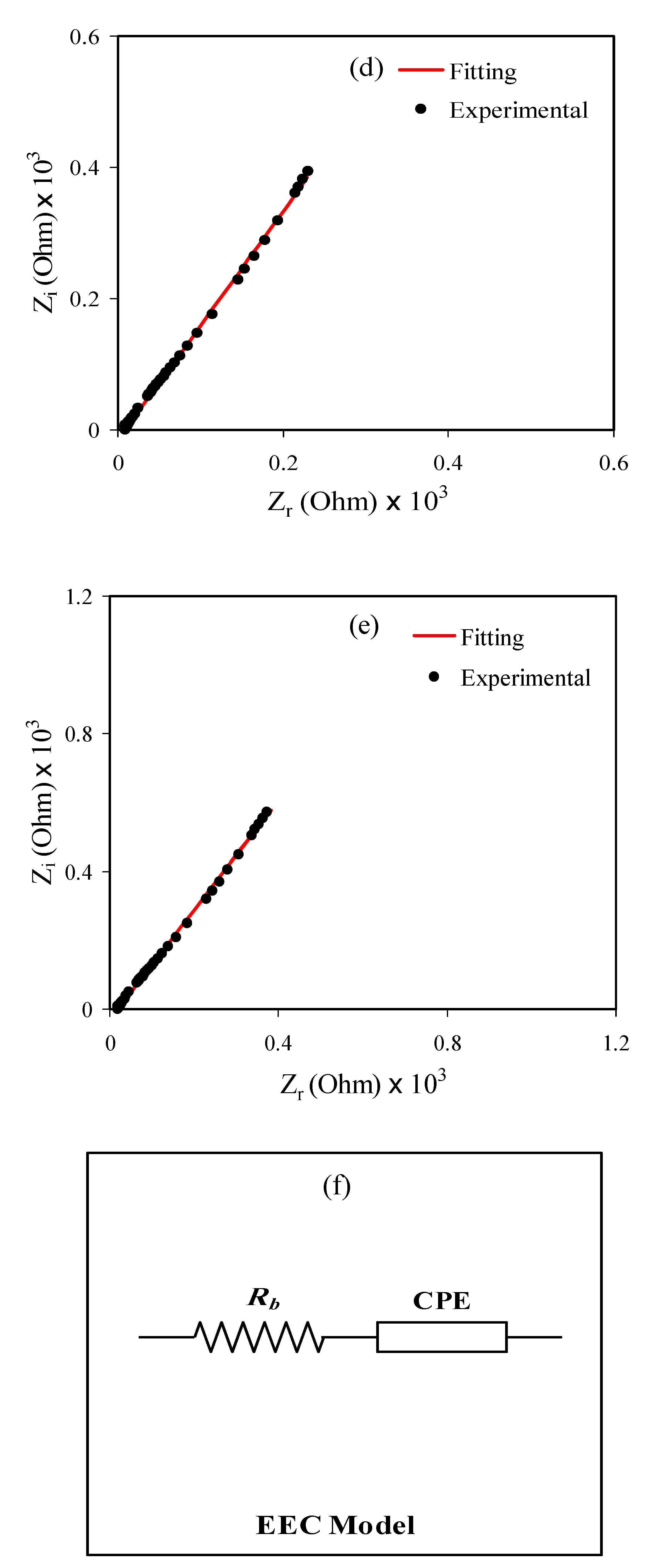
3.1. Impedance and Ion Transport Parameters Study

Insight into the charge transport mechanism in ion-conducting materials is of great importance fundamentally and technologically. For this purpose, electrochemical impedance spectroscopy (EIS) was used as one of the powerful techniques [39,40,41]. In this work, EIS was used to evaluate the electrical properties of the ion-conducting polymer membrane. This polymer membrane and others now have broad utilization in a range of solid–state electrochemical devices [42,43].
Figure 2a–e depicts the impedance spectra (i.e., Zi as a function of Zr) for all samples. A linear line (or spike) at the low-frequency region appears due to the electrode blocking occurrence [44,45,46]. The pseudo-capacitance causes this phenomenon at the electrode/electrolyte interface regions. The Rb values can be calculated from data analysis using the spike intercept with the spectra’s real axes. This response in the complex impedance plot is ascribed to the ionic conductivity whenever approaching the zero-phase angle [40]. Ultimately, the values of DC conductivity (σdc) values can be determined using the equation below [30]:
σ d c = 1 R b × t A ,
where the surface area and thickness of the sample are symbolized by A and t, respectively. To decide on the eligibility of an electrolyte for utilization in electrochemical devices, the value of ionic conductivity has to be known as a critical factor. The plasticizer quantity is critical in enhancing the conductivity of the electrolyte (see Table 2). It is intuition that two factors govern the conductivity; charge carrier numbers and ion mobility (in other words, size, and electronegativity of ion).
In the current study, 50 wt.% of NaI salt is optimum to provide enough charge carrier density. It has been well documented that polymer electrolytes possess high conductivity in the presence of ions. The mathematical relations of conductivity in one side with charge number density and ion mobility on the other side formulated can be shown below [3]:
σ = i n i q i μ i ,
where n i , q i , and μ i represent the charge carrier number (or only charge number), electron charge, and the mobility of the ion (here i is the identity of the ion), respectively [5]. From Equation (9), it is evident that a direct proportionality among conductivity (σ) and charge number ( n i ) and the ionic mobility ( μ i ) in electrolytes is present. The former study has emphasized that the high number of charges results from salt dissociation using volatile solvents in the matrices of appropriate polymers that are compatible [47]. The trend of decreasing Rb is caused by increasing glycerol content ranging from 10 to 40 wt.%. This can be considered as an indication of glycerol’s effect in providing a high amount of free ions throughout the polymer bodies by softening the polymer backbone. The glycerol plasticizer can dissociate more salts and disrupt hydrogen bonding between polymer chains. Thus, this improves the overall amorphous phase of the prepared samples, which acts as a pathway for ion conduction. Additionally, more free ion will be available for conduction [18,19].
The electrical equivalent circuit (EEC) model was studied to have better insight into the ion migration. This model is simple and it can provide a clear picture of the whole polymer electrolyte system [41,48]. From the impedance plot of the samples (Figure 2e) the equivalent circuit (EC), which comprises R b for the charge species in the prepared polymer electrolyte systems and a constant phase elements (CPE) is series, as presented in Figure 2f. Figure 2a–e shows the fitting of the experimental data point of each film’s impedance spectra.
The impedance of CPE (ZCPE) can be imagined using the equations shown below [15,31,49]:
Z C P E = 1 C ω p [ cos ( π p 2 ) i sin ( π p 2 ) ]
where C, ω, and p are the CPE capacitance, the angular frequency, and the deviation of the spectra from the axis, respectively.
For the B3-labeled electrolyte sample, from the only spike, Rb is combined in series with CPE, the mathematical impedance relationship can be expressed as follow [31]:
Z r = cos ( π p 2 ) C ω p + R b
Z i = sin ( π p 2 ) C ω p
The above equations can also determine the fitting parameters (CPE1 and CPE2) and accurately measure the R b values. The determined CPE values for the PVNA1, PVNA2, PVNA3, PVNA4, and PVNA5-labelled electrolytes, respectively, are presented in Table 3. The relatively maximum conductivity value obtained for the PVNA4 electrolyte sample indicates the electrolyte’s eligibility for ion-conducting devices. This is because the conductivity of polymer electrolyte plays the key role in the overall performance of the electrochemical devices [50]. A good conductivity range must lie between 10−3 to 10−5 S cm [50].
All transport parameters, such as number density (n), diffusion coefficient (D), and mobility (μ) of the ions are determined from the impedance data consisting only of a spike using equations shown below [51]:
The following relationships used to calculate the diffusion coefficient of the ion carriers [51]:
D = D ° exp { 0.0297 [ ln D ° ] 2 1.4348 ln D ° 14.504 }
and
D °   = 4 k 2 l 2 R b 4 ω min 3 .
Here, l is the film thickness of the electrolyte, and ωmin is the angular frequency referring to the minimum Zi.
The mobility (μ) of the ion carriers is determined from Equation (15) [51],
μ   = e D K b T ,
where T and kb are the absolute temperature and the Boltzmann constant, respectively.
The DC conductivity of ions can be obtained from the following relationship [51]:
σ D c = n e μ .
Herein, it is easy to calculate the number density of ion carriers (n) using Equation (16).
Table 4 depicts the ion transport parameters and the corresponding ωmin values of the whole electrolyte systems.
Table 4 presents the diffusion coefficient D value where an increase was recorded with the addition of the glycerol content from 10 to 50 wt.%. A similar trend is obtained for μ as presented in Table 4. These rises in D and μ are strongly correlated to the chain flexibility enhancement with glycerol. The glycerol with high dielectric constant has the power to weaken the attraction force between ion species (cations and anions); in addition, it can disrupt bonding between the host polymer chains which enhance the segmental motion. These two factors will result in improving the overall conductivity of the polymer electrolyte upon the addition of glycerol. It is also noted that the n values increase as a result of conductivity enhancement. As documented previously, the higher the glycerol addition, the more tendency of the salts to dissociate to free ions; thereby, the number density of charge carriers increases as well [51]. Hence, a higher number of NH₄⁺ (ni) can be generated by NaI to the polymer. The rising dielectric constant of polymer electrolytes moving towards a low frequency at which the capacitance would increase was the important note reported [52]. The capacitance also increases with increasing the glycerol content. As the number density of free ions increases (see Table 4), the dielectric constant value increases, due to the high value of dielectric constant of the used glycerol, which can dissociate more salt and high carrier density can be achieved.

3.2. SPE Film Characteristic for EDLC Application

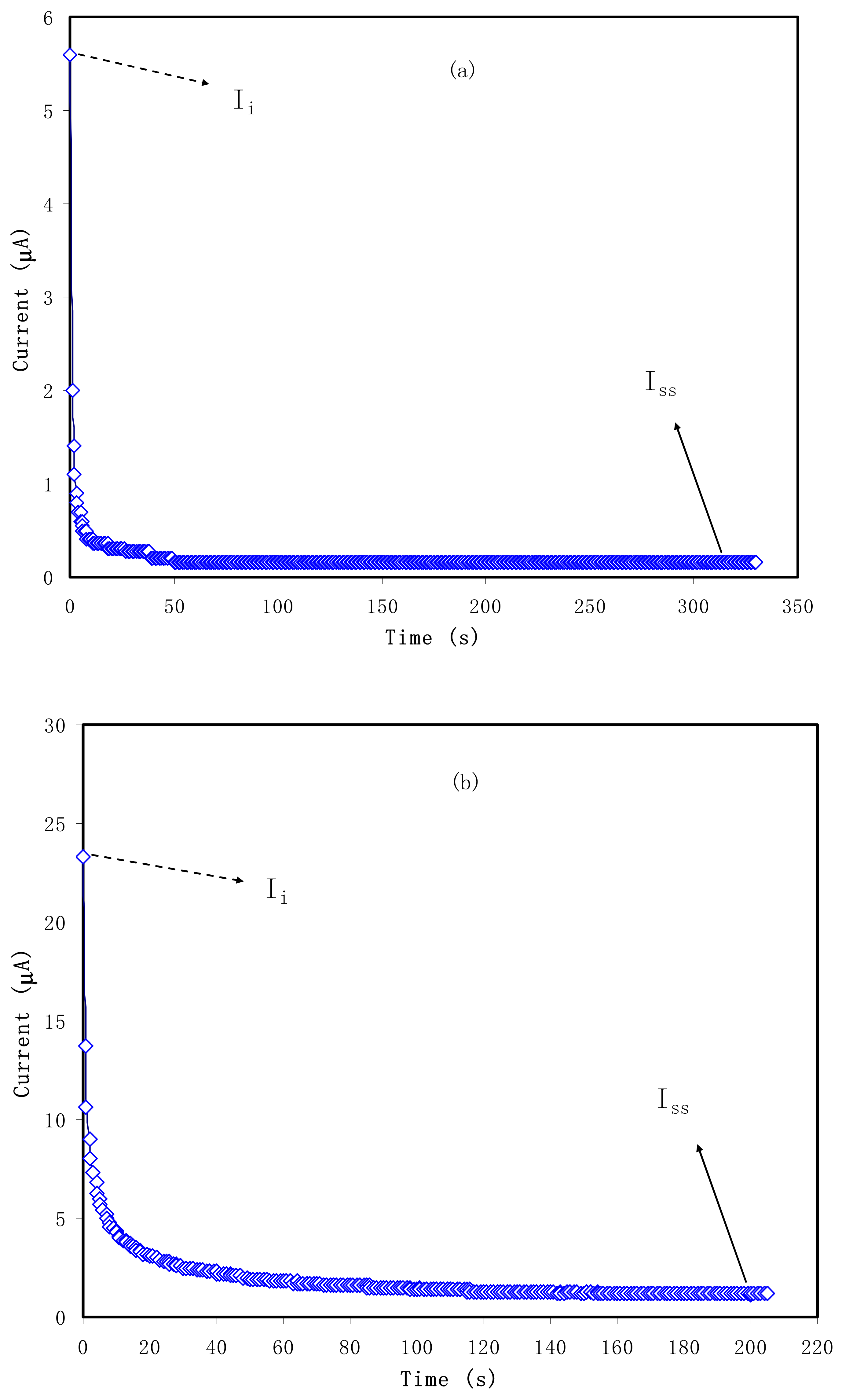
3.2.1. Transference Number Measurement
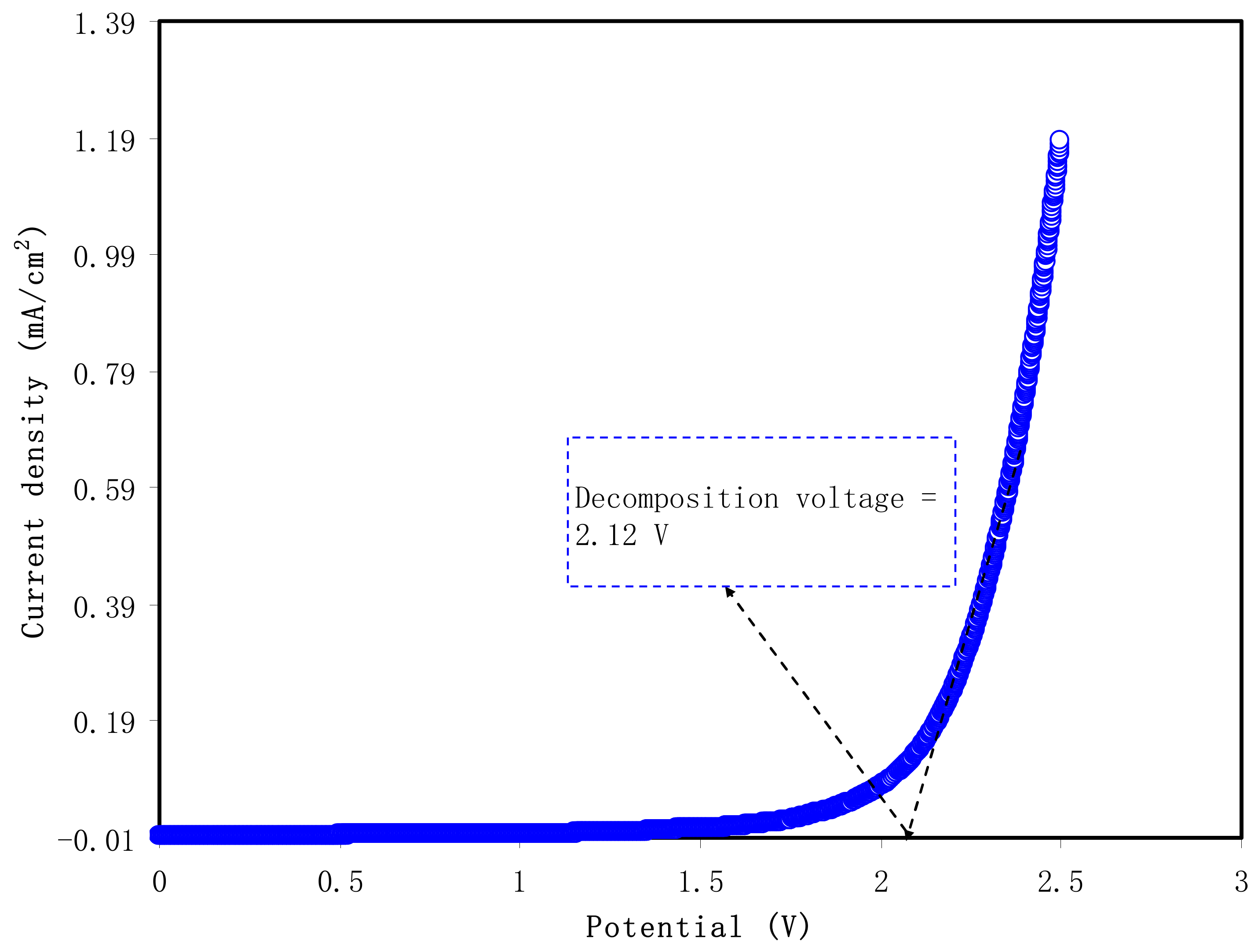
The quantity of ti has to approach unity to utilize the electrolyte in EDLCs. In such systems, ions are the primary charge carriers compared to the electron. In principle, electron and ion are two types of charge-carrying species. Solid-state ionic is one branch of physics that deals with ionic transport properties of solids that possess reasonably high ionic conductivity [53]. Solid electrolytes (or super ion conductors, SICs) represent those materials characterized by the superiority of the ionic conductivity over electronic ones by recording 10−6 S cm−1 and 10−12 S cm−1, respectively, at room temperature [54,55]. Na+ and I ions are the two main species that perform adsorption at the AC electrodes’ surface in the present systems. In Figure 3a,b, the maximum current is recorded at the beginning and then a great fall occurs. Due to omitting the ionic conduction in the stainless steel electrodes, the decrease of the whole current in the transient profile is expected. The ti observed in our study has acceptable value and consistent with what has been reported in the literature for various polymer electrolyte systems [11,18,30,31]. The relatively high value of ti of the present electrolyte indicates to a large extent the eligibility of the electrolyte to be commercialized by using in EDLCs. In PVNA4 sample tion = 0.982, which is larger than tion = 0.948 for PVNA5 sample. Thus, PVNA4 polymer electrolyte was used in the EDLC fabrication.
The ti value for the system composed of CS:MgCl2:glycerol was found to be 0.971. That is likely because of the dominancy of the charge transport in this polymer electrolyte by ions. Polu and Kumar [56] have given a ti of 0.96 for the system involving Mg(CH3COO)2 salt with PVA host. From the literature, it was recorded that I-carrageenan:Mg(NO3)2 [57] and PEG:Mg(CH3COO)2:CeO2 [58] possessed the ti value of 0.97. Thus the tion accomplished in the existing study is of great prominence.

3.2.2. LSV Analysis

The voltage window as a measure of the polymer electrolyte system’s electrochemical stability is highly significant from a commercialization perspective [59,60]. Figure 4 shows LSV response as potential dynamic scanning in a cell containing PVA:NaI:GL electrolyte. The LSV pattern of the tested sample was providing a good insight into the suitability of used sample for the electrochemical device applications, particularly EDLC. This is because during the charge–discharge process of the EDLC, a high voltage will build up on the electrolyte, which might result in the decomposition of the used electrolyte and cause device failure. From Figure 4, one can note that there is no considerable increment in the value of current up to 2 V. However, there is a sharp rise in the value of current when the applied voltage reaches above 2.12 V. This exponential ascent in current is the clear sign of the decomposition of the electrolyte within the electrodes. This means that the range of voltage window for polymer blend electrolytes is around 2.12 V, which is enough for utilization in EDLCs [61]. Monisha et al. [62] have defined the threshold voltage, that is, voltage window, as the range of electrochemical stability within which current flow through the cells leads not to electrolytic decomposition. In other words, the solvent evaporation, leakage of liquid, and relatively low electrolyte breakdown voltage (<1 V) of electrolytes, in particular, are detrimental, causing low SCDs performance [63].

3.3. EDLC Characteristics

3.3.1. Cyclic Voltammetry (CV)

To evaluate the performance of the EDLC, CV was recorded. Figure 5 shows the influence of scan rate of the main feature of CV shape. It is seen that the main feature of the CV of leaf shapes has remained similar at all chosen scan rates. A perfect capacitor is characterized by a common feature that is an ideal rectangular shape of the CV electrochemical signal. Nevertheless, in reality, the main features of CV have changed dramatically due to the nature of electrode surface (porosity), which causes changes in internal resistance. This alteration in CV response results in changing EDLC performance as well as efficiency. Besides, the I-V response is also impacted [64].
It can be noticed that no redox peak is observed over the voltage range of scanning. This indicates the occurrence of charge storing via anon-faradaic procedure, which is a basis of EDLCs. According to this procedure, both cations and anions adsorb and desorb at electrode surfaces, that is, intercalation and deintercalation processes are absent [65].
Table 5 presents the Ccyc values, where the maximum is recorded at a low scan rate and gradually decreasing as the scan rate increases. In principle, at a low scan rate, a stable double-layer charge forms from the adsorption of ions at the interfacial region. Here, the common question arises why an almost perfect plateau is obtainable at a low scan rate. The answer is the building up of a thick diffuse layer from ion adsorption at the interfacial region. This also causes small ohmic resistance. On the contrary, a thin, diffuse layer at a high scan rate is formed and consequently small capacitance is resulted [66].

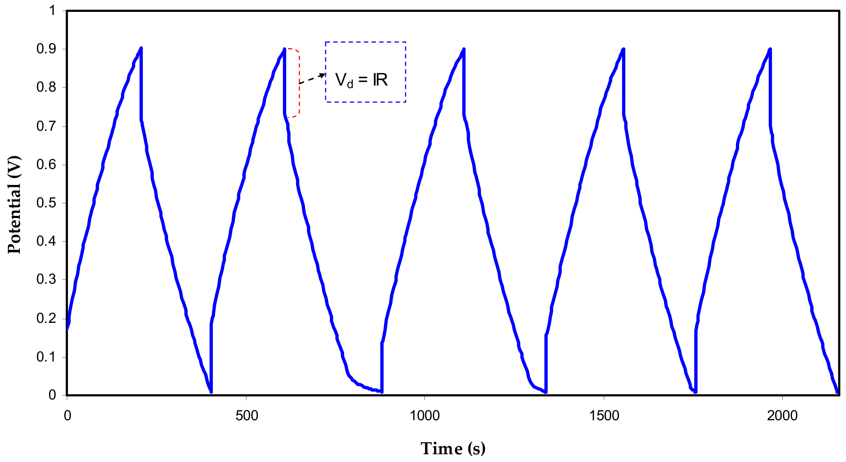
3.3.2. Charge-Discharge of the EDLC and Other Parameters

The charge-discharge plot’s response at a range of cycles of the EDLC is depicted in Figure 6. Charging and discharging of EDLC was occurred in this range (0–0.9 V), respectively, at a constant current density, that is, 0.75 mA/cm2. The curve’s main feature is linearity from which the slope can be determined, and capacitor behavior can be evidenced for the mechanism of storage in EDLC [67]. More observation comprises a drop in voltage (Vd = IR) before starting the discharge process and producing an ohmic drop. Another desired property of EDLC assembly is the low equivalent series resistance (ESR). This type of resistance originates from several reasons; bulk resistance of the electrolyte and a drop in IR between the electrolyte and current collectors [68,69].
More insight into the EDLC assembly is obtained from the ESR response vs. cycle numbers Figure 7. At the 1st cycle, the ESR value of 91.2 Ohm is recorded and then remains unchanged until the 50th cycle with the average value of 95.4 Ohm for the EDLC assembly. The ESR values rise as the cycle number increases until the 100th cycle, reaching 101.7 Ohm and becomes constant at the 400th cycle. During the experimental cycling course, a minute increase in ESR occurs throughout the 400th cycle; similarly, the same trend is recorded for the specific capacitance. It is interesting to note that small record data of ESR suggests a satisfactory EDLC assembly with compatible electrolyte|electrode contact. This means that the overall mechanism is the migration of ions from the bulk electrolyte region to the activated carbon surface. Building up the space charge double-layer had a relatively low internal resistance [70].
The capacitance is expressed by the ratio of change in the electric charge corresponding to its electric potential in a given system. The Ccd value of the EDLC assembly can be acquired from the response, as shown in Figure 8. As expected, the capacitance value is 169 F/g at the 1st cycle. This value is relatively large compared to that recorded for other PVA-based electrolytes incorporated with ammonium salts [21,37,50]. After the 1st cycle an enormous lessening of Cspe was detected. A former study recognized that ion aggregate formation or ion pairs could be accountable for the deterioration of electrical conductivity [71]. It was proven that ion pairs could block the ion transportation through the polymer electrolyte, therefore impacting the degree at which ions are adsorbed at the carbon pores. Accordingly, this drops the growth of ion adsorption at the electrodes-electrolyte boundaries and thus reduces the Cspe value [1,72].
Notably, an average value of 97.2 F/g is recorded as a constant value of Ccd during the whole 400 cycles. This relatively high value of Ccd can be attributed to the large surface area of activated carbon (2500 m2/g). More explanation for this situation comes from the fact that many free ions from NaI salt enable the electrode surface to occupy the electrode surface via an adsorption/desorption mechanism.
Francis et al. [73] have recently studied PVA-Mg(CF3SO3)2 in an EDLC assembly with recording a Ccd value that lies in the range 15 to 45 F/g. Pandey et al. [59] examined magnesium salt-based EDLC assembly that gave a Ccd value in the range of 31 to 41 F/g. Another studied system consisted of a cellulose derivative as the polymer host (hydroxylethyl cellulose, HEC) and Mg(CF3SO3)2 as the ionic provider and silica nanoparticles as additives that recorded a Ccd of 25.1 F/g [66].
The energy density (E) means measuring the speed up of energy up-taking in a confined specific space per unit volume. Figure 9 presents E variations over a wide range of 400 cycles. The energy density is directly proportional to the specific capacitance, as mathematically shown in Equation (6). This is the cause of E and Ccd similar trends, as shown in Figure 9.
An EDLC assembly containing polyacrylonitrile-magnesium chloride (MgCl2) electrolyte with the documented energy density of 5 Wh/kg was examined by Bandaranayake et al. [74]. Winie et al. [75] reported chitosan-based EDLC assembly possessing an energy density in-between (0.57–2.8 Wh/kg) that corresponds to current densities of 2 to 0.6 mA/cm2, respectively. The literature recommends that reaching an energy density of (5.48 Wh/kg) is desired. Another important notice is that the values of E and Ccd responses are stable, evidencing least ion recombination to create ion pairs or agglomerates, which in turn minimize EDLC performance.
To fully evaluate the EDLC, the power density (P) has to be determined. It is practically essential that batteries are inferior to EDLCs based on low power density. This is because of the dominancy of ion adsorption over intercalation at the electrode surface in the EDLC. The trend of the power density of the EDLC assembly is exhibited in Figure 10. At the 1st cycle, the recorded value of power density (P) is almost 600 W/kg, whereas it gradually drops to 400 W/kg and becoming constant at the high cycle numbers. Yassine et al. [76] have established a strong relationship between ESR and power density by verifying the consistent trends of increasing the two parameters, as exhibited in Figure 10. More clearly, the high ESR value means facilitating energy delivery, confirming a large power density.

4. Conclusions

In conclusion, plasticized sodium ion-conducting polymer electrolytes based on the PVA via solution cast technique were fabricated successfully for energy storage application with enhanced Cspe (169 F/g), energy density (19 Wh/kg) and power density (600 W/kg). The influence of plasticization on conductivity behavior was studied via the EIS technique. The conductivity of the plasticized films was determined via EIS experimental data fitted with the EEC model. The ion transport parameters at various concentrations of plasticizer achieved from EIS data establish plasticizer’s influence on transport properties. The sample with 40 wt.% of glycerol has shown the highest conductivity of 1.17 × 10⁻³ S cm−1. The TNM study revealed that ion transference number improved up to 40 wt.% of plasticizer with the highest tion = 0.982 and then drops for the higher concentration of plasticizer. The LSV analysis revealed that the electrolyte is stable up to 2.12 V for device fabrication, and the sample represented good stability in a wide range of potential windows. The average value of specific capacitance for the assembled EDLC was found to be 97.2 F/g over 400 cycles. The charge-discharging response on the assembly EDLC device provides information on ion accumulation between the electrode and electrolyte. The absence of redox peaks was proved via CV, indicating the charge storing process mechanism that comprised ion accumulation at the interfacial region. The designed EDLC performed good energy and power densities with average values above 10 Wh/kg and 300 W/kg up to 400 cycles, respectively.

Author Contributions

Conceptualization, S.B.A. and M.F.Z.K.; Data curation, R.M.A.; Formal analysis, S.B.A. and R.T.A.; Funding acquisition, M.M.N. and E.M.A.D.; Investigation, M.H.H.; Project administration, S.B.A., M.M.N. and M.F.Z.K.; Supervision, S.B.A.; Validation, M.M.N., R.T.A., H.O.G., E.M.A.D., R.M.A. and M.H.H.; Writing—original draft, S.B.A.; Writing—review & editing, M.M.N., R.T.A., H.O.G., E.M.A.D., R.M.A., M.H.H. and M.F.Z.K. All authors have read and agreed to the published version of the manuscript.

Funding

This research received no external funding.

Institutional Review Board Statement

Not applicable.

Informed Consent Statement

Not applicable.

Data Availability Statement

The data presented in this study are available on request from the corresponding author.

Acknowledgments

We would like to acknowledge all support for this work by the University of Sulaimani, Komar University of Science and Technology, University of Malaya and Prince Sultan University. The authors would like to acknowledge the support of Prince Sultan University for paying the Article Processing Charges (APC) of this publication and for their financial support.

Conflicts of Interest

The authors declare no conflict of interest.

References

  1. Hamsan, M.H.; Shukur, M.F.; Aziz, S.B.; Yusof, Y.M.; Kadir, M.F.Z. Influence of NH4Br as an ionic source on the structural/electrical properties of dextran-based biopolymer electrolytes and EDLC application. Bull. Mater. Sci. 2020, 43, 1–7. [Google Scholar] [CrossRef]
  2. Aziz, S.B. Modifying Poly(Vinyl Alcohol) (PVA) from Insulator to Small-Bandgap Polymer: A Novel Approach for Organic Solar Cells and Optoelectronic Devices. J. Electron. Mater. 2016, 45, 736–745. [Google Scholar] [CrossRef]
  3. Aziz, S.B. Li+ ion conduction mechanism in poly (ε-caprolactone)-based polymer electrolyte. Iran. Polym. J. 2013, 22, 877–883. [Google Scholar] [CrossRef] [Green Version]
  4. Sownthari, K.; Suthanthiraraj, S.A. Synthesis and characterization of an electrolyte system based on a biodegradable polymer. Express Polym. Lett. 2013, 7, 495–504. [Google Scholar] [CrossRef]
  5. Aziz, S.B.; Abidin, Z.H.Z. Ion-transport study in nanocomposite solid polymer electrolytes based on chitosan: Electrical and dielectric analysis. J. Appl. Polym. Sci. 2015, 132, 1–10. [Google Scholar] [CrossRef]
  6. Tominaga, Y.; Asai, S.; Sumita, M.; Panero, S.; Scrosati, B. Fast ionic conduction in PEO-based composite electrolyte filled with ionic liquid-modified mesoporous silica. Electrochem. Solid State Lett. 2005, 8, 22–25. [Google Scholar] [CrossRef]
  7. Aziz, S.B. The Mixed Contribution of Ionic and Electronic Carriers to Conductivity in Chitosan Based Solid Electrolytes Mediated by CuNt Salt. J. Inorg. Organomet. Polym. Mater. 2018, 28, 1942–1952. [Google Scholar] [CrossRef]
  8. Salleh, N.S.; Aziz, S.B.; Aspanut, Z.; Kadir, M.F.Z. Electrical impedance and conduction mechanism analysis of biopolymer electrolytes based on methyl cellulose doped with ammonium iodide. Ionics 2016, 22, 2157–2167. [Google Scholar] [CrossRef]
  9. Aziz, S.B.; Abidin, Z.H.Z. Electrical and morphological analysis of chitosan:AgTf solid electrolyte. Mater. Chem. Phys. 2014, 144, 280–286. [Google Scholar] [CrossRef]
  10. Aziz, S.B. Role of dielectric constant on ion transport: Reformulated Arrhenius equation. Adv. Mater. Sci. Eng. 2016, 2016, 2527013. [Google Scholar] [CrossRef] [Green Version]
  11. Aziz, S.B.; Kadir, M.F.Z.; Abidin, Z.H.Z. Structural, morphological and electrochemical impedance study of CS: LiTf based solid polymer electrolyte: Reformulated arrhenius equation for ion transport study. Int. J. Electrochem. Sci. 2016, 11, 9228–9244. [Google Scholar] [CrossRef]
  12. Marf, A.S.; Abdullah, R.M.; Aziz, S.B. Structural, morphological, electrical and electrochemical properties of PVA: CS-based proton-conducting polymer blend electrolytes. Membranes 2020, 10, 71. [Google Scholar] [CrossRef] [PubMed]
  13. Sundaramahalingam, K.; Muthuvinayagam, M.; Nallamuthu, N.; Vanitha, D.; Vahini, M. Investigations on lithium acetate-doped PVA/PVP solid polymer blend electrolytes. Polym. Bull. 2019, 76, 5577–5602. [Google Scholar] [CrossRef]
  14. Saroj, A.L.; Krishnamoorthi, S.; Singh, R.K. Structural, thermal and electrical transport behaviour of polymer electrolytes based on PVA and imidazolium based ionic liquid. J. Non-Cryst. Solids 2017, 473, 87–95. [Google Scholar] [CrossRef]
  15. Aziz, S.B.; Woo, T.J.; Kadir, M.F.Z.; Ahmed, H.M. A conceptual review on polymer electrolytes and ion transport models. J. Sci. Adv. Mater. Devices 2018, 3, 1–17. [Google Scholar] [CrossRef]
  16. Jaafar, N.K.; Lepit, A.; Aini, N.A.; Saat, A.; Ali, A.M.M.; Yahya, M.Z.A. Effects of lithium salt on chitosan-g-PMMA based polymer electrolytes. Mater. Res. Innov. 2011, 15. [Google Scholar] [CrossRef]
  17. Liu, W.; Lin, D.; Sun, J.; Zhou, G.; Cui, Y. Improved Lithium Ionic Conductivity in Composite Polymer Electrolytes with Oxide-Ion Conducting Nanowires. ACS Nano 2016, 10, 11407–11413. [Google Scholar] [CrossRef] [PubMed]
  18. Shukur, M.F.; Ithnin, R.; Kadir, M.F.Z. Ionic conductivity and dielectric properties of potato starch-magnesium acetate biopolymer electrolytes: The effect of glycerol and 1-butyl-3-methylimidazolium chloride. Ionics 2016, 22, 1113–1123. [Google Scholar] [CrossRef]
  19. Chai, M.N.; Isa, M.I.N. Novel Proton Conducting Solid Bio-polymer Electrolytes Based on Carboxymethyl Cellulose Doped with Oleic Acid and Plasticized with Glycerol. Sci. Rep. 2016, 6, 27328. [Google Scholar] [CrossRef]
  20. Mattos, R.I.; Raphael, E.; Majid, S.R.; Arof, A.K.; Pawlicka, A. Enhancement of electrical conductivity in plasticized chitosan based membranes. Mol. Cryst. Liq. Cryst. 2012, 554, 150–159. [Google Scholar] [CrossRef]
  21. Marf, A.S.; Aziz, S.B.; Abdullah, R.M. Plasticized H+ ion-conducting PVA:CS-based polymer blend electrolytes for energy storage EDLC application. J. Mater. Sci. Mater. Electron. 2020. [Google Scholar] [CrossRef]
  22. Yan, J.; Wang, Q.; Wei, T.; Fan, Z. Recent advances in design and fabrication of electrochemical supercapacitors with high energy densities. Adv. Energy Mater. 2014, 4, 1300816. [Google Scholar] [CrossRef]
  23. Cevik, E.; Gunday, S.T.; Akhtar, S.; Bozkurt, A. A comparative study of various polyelectrolyte/nanocomposite electrode combinations in symmetric supercapacitors. Int. J. Hydrogen Energy 2019, 44, 16099–16109. [Google Scholar] [CrossRef]
  24. Cevik, E.; Gunday, S.T.; Bozkurt, A.; Amine, R.; Amine, K. Bio-inspired redox mediated electrolyte for high performance flexible supercapacitor applications over broad temperature domain. J. Power Sources 2020, 474, 228544. [Google Scholar] [CrossRef]
  25. Cevik, E.; Bozkurt, A. Redox active polymer metal chelates for use in flexible symmetrical supercapacitors: Cobalt-containing poly(acrylic acid) polymer electrolytes. J. Energy Chem. 2021, 55, 145–153. [Google Scholar] [CrossRef]
  26. Cevik, E.; Bozkurt, A.; Dirican, M.; Zhang, X. High performance flexible supercapacitors including redox active molybdate incorporated Poly(vinylphosphonic acid) hydrogels. Int. J. Hydrogen Energy 2020, 45, 2186–2194. [Google Scholar] [CrossRef]
  27. Cevik, E.; Bozkurt, A.; Hassan, M.; Gondal, M.A.; Qahtan, T.F. Redox-Mediated Poly(2-acrylamido-2-methyl-1-propanesulfonic acid)/Ammonium Molybdate Hydrogels for Highly Effective Flexible Supercapacitors. ChemElectroChem 2019, 6, 2876–2882. [Google Scholar] [CrossRef]
  28. Hamsan, M.H.; Aziz, S.B.; Azha, M.A.S.; Azli, A.A.; Shukur, M.F.; Yusof, Y.M.; Muzakir, S.K.; Manan, N.S.A.; Kadir, M.F.Z. Solid-state double layer capacitors and protonic cell fabricated with dextran from Leuconostocmesenteroides based green polymer electrolyte. Mater. Chem. Phys. 2020, 241. [Google Scholar] [CrossRef]
  29. Pal, B.; Yang, S.; Ramesh, S.; Thangadurai, V.; Jose, R. Electrolyte selection for supercapacitive devices: A critical review. Nanoscale Adv. 2019, 1, 3807–3835. [Google Scholar] [CrossRef] [Green Version]
  30. Brza, M.A.; Aziz, S.B.; Anuar, H.; Ali, F.; Hamsan, M.H.; Kadir, M.F.Z.; Abdulwahid, R.T. Metal framework as a novel approach for the fabrication of electric double layer capacitor device with high energy density using plasticized Poly(vinyl alcohol): Ammonium thiocyanate based polymer electrolyte. Arab. J. Chem. 2020, 13, 7247–7263. [Google Scholar] [CrossRef]
  31. Aziz, S.B.; Hamsan, M.H.; Nofal, M.M.; San, S.; Abdulwahid, R.T.; Saeed, S.R.R.; Brza, M.A.; Kadir, M.F.Z.; Mohammed, S.J.; Al-Zangana, S. From Cellulose, Shrimp and Crab Shells to Energy Storage EDLC Cells: The Study of Structural and Electrochemical Properties of Proton Conducting Chitosan-Based Biopolymer Blend Electrolytes. Polymers 2020, 12, 1526. [Google Scholar] [CrossRef] [PubMed]
  32. Aziz, S.B.; Brza, M.A.; Hamsan, H.M.; Kadir, M.F.Z.; Abdulwahid, R.T. Electrochemical characteristics of solid state double-layer capacitor constructed from proton conducting chitosan-based polymer blend electrolytes. Polym. Bull. 2020, 1–19. [Google Scholar] [CrossRef]
  33. Śliwak, A.; Díez, N.; Miniach, E.; Gryglewicz, G. Nitrogen-containing chitosan-based carbon as an electrode material for high-performance supercapacitors. J. Appl. Electrochem. 2016, 46, 667–677. [Google Scholar] [CrossRef] [Green Version]
  34. Asnawi, A.S.F.M.; Aziz, S.B.; Saeed, S.R.; Yusof, Y.M.; Abdulwahid, R.T.; Al-Zangana, S.; Karim, W.O.; Kadir, M.F.Z. Solid-state EDLC device based on magnesium ion-conducting biopolymer composite membrane electrolytes: Impedance, circuit modeling, dielectric properties and electrochemical characteristics. Membranes 2020, 10, 389. [Google Scholar] [CrossRef]
  35. Aziz, S.B.; Abdulwahid, R.T.; Rasheed, M.A.; Abdullah, O.G.H.; Ahmed, H.M. Polymer blending as a novel approach for tuning the SPR peaks of silver nanoparticles. Polymers 2017, 9, 486. [Google Scholar] [CrossRef]
  36. Zhao, X.Y.; Wu, Y.; Cao, J.P.; Zhuang, Q.Q.; Wan, X.; He, S.; Wei, X.Y. Preparation and characterization of activated carbons from oxygen-rich lignite for electric double-layer capacitor. Int. J. Electrochem. Sci. 2018, 13, 2800–2816. [Google Scholar] [CrossRef] [Green Version]
  37. Aziz, S.B.; Hadi, J.M.; Elham, E.M.; Abdulwahid, R.T.; Saeed, S.R.; Marf, A.S.; Karim, W.O.; Kadir, M.F.Z. The study of plasticized amorphous biopolymer blend electrolytes based on polyvinyl alcohol (PVA): Chitosan with high ion conductivity for energy storage electrical double-layer capacitors (EDLC) device application. Polymers 2020, 12, 1938. [Google Scholar] [CrossRef]
  38. Islam, I.; Sultana, S.; Ray, S.K.; ParvinNur, H.; Hossain, M.; Ajmotgir, W.M. Electrical and Tensile Properties of Carbon Black Reinforced Polyvinyl Chloride Conductive Composites. C J. Carbon Res. 2018, 4, 15. [Google Scholar] [CrossRef] [Green Version]
  39. Machappa, T.; Prasad, M.V.N.A. AC conductivity and dielectric behavior of polyaniline/sodium metavenadate (PANI/NaVO3) composites. Phys. B Condens. Matter 2009, 404, 4168–4172. [Google Scholar] [CrossRef]
  40. Aziz, S.B. Occurrence of electrical percolation threshold and observation of phase transition in chitosan (1−x):AgI x (0.05 ≤ x ≤ 0.2)-based ion-conducting solid polymer composites. Appl. Phys. A Mater. Sci. Process. 2016, 122, 706. [Google Scholar] [CrossRef]
  41. Aziz, S.B.; Abdullah, R.M.; Kadir, M.F.Z.; Ahmed, H.M. Non suitability of silver ion conducting polymer electrolytes based on chitosan mediated by barium titanate (BaTiO3) for electrochemical device applications. Electrochim. Acta 2019, 296, 494–507. [Google Scholar] [CrossRef]
  42. Aziz, S.B. Study of electrical percolation phenomenon from the dielectric and electric modulus analysis. Bull. Mater. Sci. 2015, 38, 1597–1602. [Google Scholar] [CrossRef]
  43. Nasef, M.M.; Saidi, H.; Dahlan, K.Z.M. Preparation of composite polymer electrolytes by electron beam-induced grafting: Proton- and lithium ion-conducting membranes. Nucl. Instrum. Methods Phys. Res. Sect. B Beam Interact. Mater. Atoms 2007, 265, 168–172. [Google Scholar] [CrossRef] [Green Version]
  44. Selvasekarapandian, S.; Baskaran, R.; Hema, M. Complex AC impedance, transference number and vibrational spectroscopy studies of proton conducting PVAc-NH4SCN polymer electrolytes. Phys. B Condens. Matter. 2005, 357, 412–419. [Google Scholar] [CrossRef]
  45. Malathi, J.; Kumaravadivel, M.; Brahmanandhan, G.M.; Hema, M.; Baskaran, R.; Selvasekarapandian, S. Structural, thermal and electrical properties of PVA-LiCF3SO3 polymer electrolyte. J. Non-Cryst. Solids 2010, 356, 2277–2281. [Google Scholar] [CrossRef]
  46. Wan, Y.; Creber, K.A.M.; Peppley, B.; Bui, V.T. Ionic conductivity of chitosan membranes. Polymer 2003, 44, 1057–1065. [Google Scholar] [CrossRef]
  47. Mendoza, N.; Paraguay-Delgado, F.; Hu, H. Effect of different acid and lithium salt used in polyethylene glycol-titanium oxide based solvent-free electrolytes on electrochromic performance of WO 3 thin films. Sol. Energy 2012, 86, 997–1003. [Google Scholar] [CrossRef]
  48. Aziz, S.B.; Abdullah, R.M. Crystalline and amorphous phase identification from the tanδ relaxation peaks and impedance plots in polymer blend electrolytes based on [CS:AgNt]x:PEO(x-1) (10 ≤ x ≤ 50). Electrochim. Acta 2018, 285, 30–46. [Google Scholar] [CrossRef]
  49. Aziz, S.B.; Karim, W.O.; Brza, M.A.; Abdulwahid, R.T.; Saeed, S.R.; Al-Zangana, S.; Kadir, M.F.Z. Ion transport study in CS: POZ based polymer membrane electrolytes using Trukhan model. Int. J. Mol. Sci. 2019, 20, 5265. [Google Scholar] [CrossRef] [PubMed] [Green Version]
  50. Aziz, S.B.; Brza, M.A.; Brevik, I.; Hafiz, M.H.; Asnawi, A.S.F.M.; Yusof, Y.M.; Abdulwahid, R.T.; Kadir, M.F.Z. Blending and Characteristics of Electrochemical Double-Layer Capacitor Device Assembled from Plasticized Proton Ion Conducting Chitosan:Dextran:NH4PF6 Polymer Electrolytes. Polymers 2020, 12, 2103. [Google Scholar] [CrossRef]
  51. Brza, M.A.; Aziz, S.B.; Anuar, H.; Ali, F. Structural, ion transport parameter and electrochemical properties of plasticized polymer composite electrolyte based on PVA: A novel approach to fabricate high performance EDLC devices. Polym. Test. 2020, 91, 106813. [Google Scholar] [CrossRef]
  52. Brza, M.A.; Aziz, S.B.; Anuar, H.; Dannoun, E.M.A.; Ali, F.; Abdulwahid, R.T.; Al-Zangana, S.; Kadir, M.F.Z. The study of EDLC device with high electrochemical performance fabricated from proton ion conducting PVA-based polymer composite electrolytes plasticized with glycerol. Polymers 2020, 12, 1896. [Google Scholar] [CrossRef] [PubMed]
  53. Bhatt, C.; Swaroop, R.; Arya, A.; Sharma, A.L. Effect of Nano-Filler on the Properties of Polymer Nanocomposite Films of PEO/PAN Complexed with NaPF6. J. Mater. Sci. Eng. B 2015, 5, 418–434. [Google Scholar] [CrossRef]
  54. Agrawal, R.C.; Gupta, R.K. Superionic solids: Composite electrolyte phase—An overview. J. Mater. Sci. 1999, 34, 1131–1162. [Google Scholar] [CrossRef]
  55. Agrawal, R.C.; Pandey, G.P. Solid polymer electrolytes: Materials designing and all-solid-state battery applications: An overview. J. Phys. D Appl. Phys. 2008, 41, 223001. [Google Scholar] [CrossRef]
  56. Polu, A.R.; Kumar, R. Ionic conductivity and discharge characteristic studies of PVA-Mg(CH3COO)2 solid polymer electrolytes. Int. J. Polym. Mater. Polym. Biomater. 2013, 62, 76–80. [Google Scholar] [CrossRef]
  57. ShanmugaPriya, S.; Karthika, M.; Selvasekarapandian, S.; Manjuladevi, R. Preparation and characterization of polymer electrolyte based on biopolymer I-Carrageenan with magnesium nitrate. Solid State Ion. 2018, 327, 136–149. [Google Scholar] [CrossRef]
  58. Polu, A.R.; Kumar, R. Preparation and characterization of PEG–Mg(CH3COO)2–CeO2 composite polymer electrolytes for battery application. Bull. Mater. Sci. 2014, 37, 309–314. [Google Scholar] [CrossRef] [Green Version]
  59. Pandey, G.P.; Kumar, Y.; Hashmi, S.A. Ionic liquid incorporated polymer electrolytes for supercapacitor application. Indian J. Chem. 2010, 49, 743–751. [Google Scholar]
  60. Hadi, J.M.; Aziz, S.B.; Mustafa, M.S.; Hamsan, M.H.; Abdulwahid, R.T.; Kadir, M.F.Z.; Ghareeb, H.O. Role of nano-capacitor on dielectric constant enhancement in PEO:NH4SCN:xCeO2 polymer nano-composites: Electrical and electrochemical properties. J. Mater. Res. Technol. 2020, 9, 9283–9294. [Google Scholar] [CrossRef]
  61. Sampathkumar, L.; Selvin, P.C.; Selvasekarapandian, S.; Perumal, P.; Chitra, R.; Muthukrishnan, M. Synthesis and characterization of biopolymer electrolyte based on tamarind seed polysaccharide, lithium perchlorate and ethylene carbonate for electrochemical applications. Ionics 2019, 25, 1067–1082. [Google Scholar] [CrossRef]
  62. Monisha, S.; Mathavan, T.; Selvasekarapandian, S.; Benial, A.M.F.; Latha, M.P. Preparation and characterization of cellulose acetate and lithium nitrate for advanced electrochemical devices. Ionics 2017, 23, 2697–2706. [Google Scholar] [CrossRef]
  63. Wang, J.; Zhao, Z.; Song, S.; Ma, Q.; Liu, R. High performance poly(vinyl alcohol)-based Li-ion conducting gel polymer electrolyte films for electric double-layer capacitors. Polymers 2018, 10, 1179. [Google Scholar] [CrossRef] [PubMed] [Green Version]
  64. Lewandowski, A.; Zajder, M.; Frackowiak, E.; Béguin, F. Supercapacitor based on activated carbon and polyethylene oxide-KOH-H2O polymer electrolyte. Electrochim. Acta 2001, 46, 2777–2780. [Google Scholar] [CrossRef]
  65. Deng, J.; Li, J.; Xiao, Z.; Song, S.; Li, L. Studies on possible ion-confinement in nanopore for enhanced supercapacitor performance in 4V EMIBF4 ionic liquids. Nanomaterials 2019, 9, 1664. [Google Scholar] [CrossRef] [Green Version]
  66. Chong, M.Y.; Numan, A.; Liew, C.W.; Ng, H.M.; Ramesh, K.; Ramesh, S. Enhancing the performance of green solid-state electric double-layer capacitor incorporated with fumed silica nanoparticles. J. Phys. Chem. Solids 2018, 117, 194–203. [Google Scholar] [CrossRef]
  67. Eftekhari, A. The mechanism of ultrafast supercapacitors. J. Mater. Chem. A 2018, 6, 2866–2876. [Google Scholar] [CrossRef]
  68. Aziz, S.B.; Hamsan, M.H.; Abdullah, R.M.; Kadir, M.F.Z. A promising polymer blend electrolytes based on chitosan: Methyl cellulose for EDLC application with high specific capacitance and energy density. Molecules 2019, 24, 2503. [Google Scholar] [CrossRef] [Green Version]
  69. Aziz, S.B.; Abdulwahid, R.T.; Hamsan, M.H.; Brza, M.A.; Abdullah, R.M.; Kadir, M.F.Z.; Muzakir, S.K. Structural, impedance, and EDLC characteristics of proton conducting chitosan-based polymer blend electrolytes with high electrochemical stability. Molecules 2019, 24, 3508. [Google Scholar] [CrossRef] [PubMed] [Green Version]
  70. Asmara, S.N.; Kufian, M.Z.; Majid, S.R.; Arof, A.K. Preparation and characterization of magnesium ion gel polymer electrolytes for application in electrical double layer capacitors. Electrochim. Acta 2011, 57, 91–97. [Google Scholar] [CrossRef]
  71. Aziz, S.B.; Abidin, Z.H.Z.; Arof, A.K. Effect of silver nanoparticles on the DC conductivity in chitosan–silver triflate polymer electrolyte. Phys. B Condens. Matter. 2010, 405, 4429–4433. [Google Scholar] [CrossRef]
  72. Azli, A.A.; Manan, N.S.A.; Aziz, S.B.; Kadir, M.F.Z. Structural, impedance and electrochemical double-layer capacitor characteristics of improved number density of charge carrier electrolytes employing potato starch blend polymers. Ionics 2020, 26, 5773–5804. [Google Scholar] [CrossRef]
  73. Francis, K.A.; Liew, C.W.; Ramesh, S.; Ramesh, K.; Ramesh, S. Ionic liquid enhanced magnesium-based polymer electrolytes for electrical double-layer capacitors. Ionics 2016, 22, 919–925. [Google Scholar] [CrossRef]
  74. Bandaranayake, C.M.; Yayathilake, Y.M.C.D.; Perera, K.S.; Vidanapathirana, K.P.; Bandara, L.R.A.K. Investigation of a gel polymer electrolyte based on polyacrylonitrile and magnesium chloride for a redox capacitor. Ceylon J. Sci. 2016, 45, 75–82. [Google Scholar] [CrossRef] [Green Version]
  75. Winie, T.; Jamal, A.; Saaid, F.I.; Tseng, T.Y. Hexanoyl chitosan/ENR25 blend polymer electrolyte system for electrical double layer capacitor. Polym. Adv. Technol. 2019, 30, 726–735. [Google Scholar] [CrossRef]
  76. Yassine, M.; Fabris, D. Performance of commercially available supercapacitors. Energies 2017, 10, 1340. [Google Scholar] [CrossRef] [Green Version]
Figure 1. Structure of glycerol.
Polymers 13 00803 g001
Figure 2. Impedance plot for the prepared polymer electrolyte systems (a) PVNA1 (b) PVNA2 (c) PVNA3 (d) PVNA4 (e) PVNA5 and (f) EEC model.
Polymers 13 00803 g002aPolymers 13 00803 g002b
Figure 3. Current polarization plot for (a) PVNA4 and (b) PVNA5.
Polymers 13 00803 g003
Figure 4. Linear sweep voltammetry (LSV) pattern and decomposition voltage for the highest conduction sample.
Polymers 13 00803 g004
Figure 5. Leaf shape cyclic voltammetry plot of the fabricated electrical double-layer capacitor (EDLC) system based on the highest conducting polymer electrolyte.
Polymers 13 00803 g005
Figure 6. Charge-discharge profile of the designed EDLC at specific cycles.
Polymers 13 00803 g006
Figure 7. Equivalent series resistance trend of the fabricated EDLC over 400 cycles.
Polymers 13 00803 g007
Figure 8. Variation in specific capacitance throughout 400 cycles.
Polymers 13 00803 g008
Figure 9. Energy density plot of the fabricated EDLC over 400 cycles.
Polymers 13 00803 g009
Figure 10. Power density trend of the fabricated EDLC over 400 cycles.
Polymers 13 00803 g010
Table 1. Sample designation with the salt plasticizer weight ratio.
DesignationNaI, wt.%Glycerol Content, wt.%
PVNA15010
PVNA25020
PVNA35030
PVNA45040
PVNA55050
Table 2. Determined ionic conductivity of the prepared samples.
DesignationConductivity (S cm−1)
PVNA12.86 × 10−5
PVNA25.75 × 10−4
PVNA39.35 × 10−4
PVNA41.17 × 10−3
PVNA59.95 × 10−4
Table 3. The capacitance of K value of the fabricated polymer electrolyte systems.
SampleK (F1)C (F)
PVNA13.28 × 1043.05 × 10−5
PVNA23.24 × 1043.09 × 10−5
PVNA32.08 × 1044.81 × 10−5
PVNA42.07 × 1044.83 × 10−5
PVNA52.75 × 1043.64 × 10−5
Table 4. Variety ion transport parameters of the prepared samples.
SampleD (cm2 s−1)μ (cm2 V−1 s)n (cm−3)
PVNA13.03 × 10−81.18 × 10−61.52 × 1020
PVNA25.62 × 10−72.19 × 10−51.64 × 1020
PVNA36.60 × 10−72.57 × 10−52.27 × 1020
PVNA47.82 × 10−73.05 × 10−53.51 × 1020
PVNA56.06 × 10−72.36 × 10−52.63 × 1020
Table 5. Variation in capacitance value concerning scan rate for the fabricated EDLC device.
Scan RateCapacitance
0.110.425
0.0517.649
0.0232.464
0.0146.867
Publisher’s Note: MDPI stays neutral with regard to jurisdictional claims in published maps and institutional affiliations.

