
Development of Bio-Inspired Hierarchical Fibres to Tailor the Fibre/Matrix Interphase in (Bio)composites


Abstract
:1. Introduction
2. Naturally Occurring Hierarchical Structures: Towards the Conception of Bio-Inspired Architectures for Composite Materials
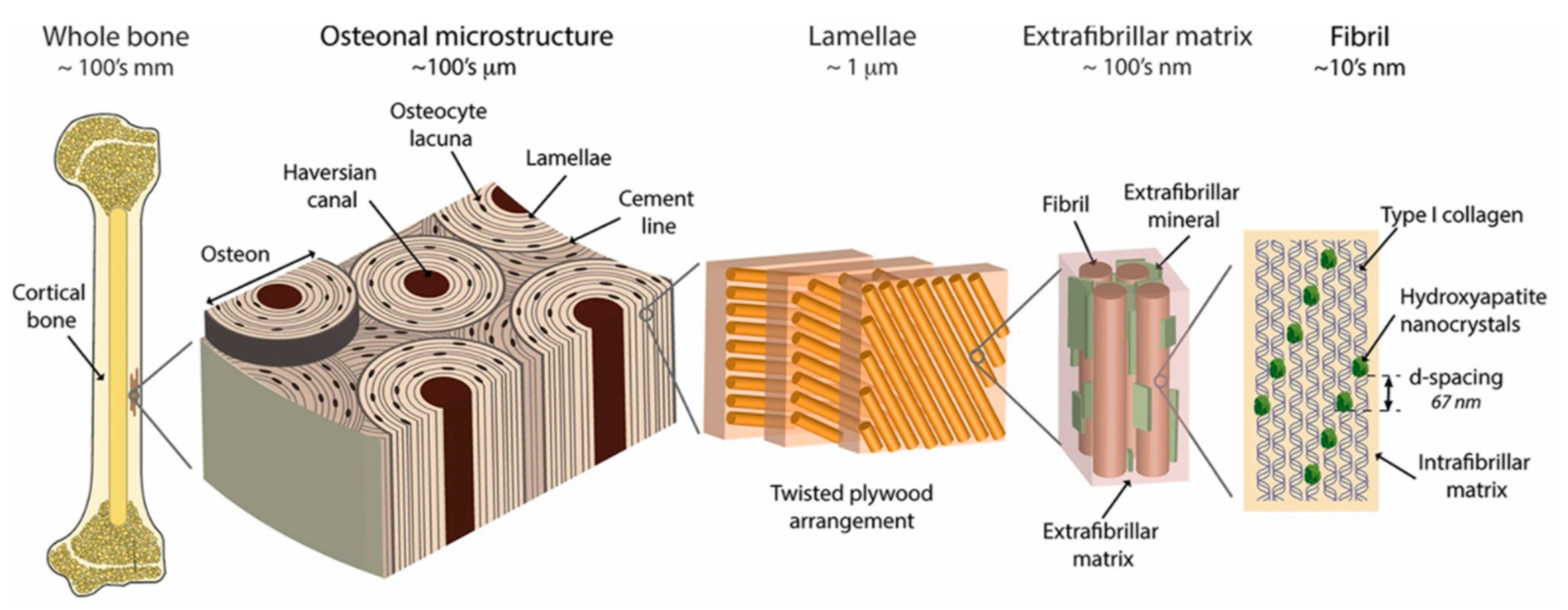
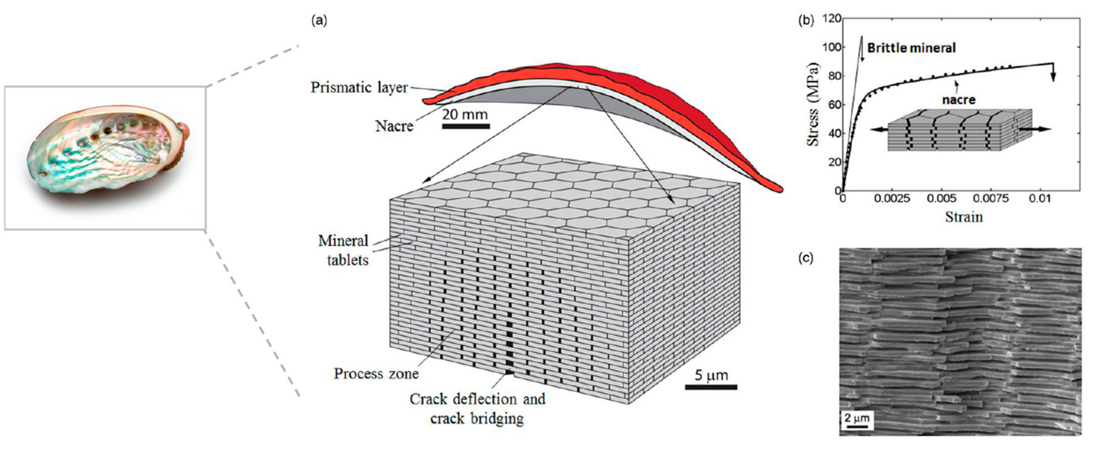
2.1. Hierarchical Structures in Biological Systems
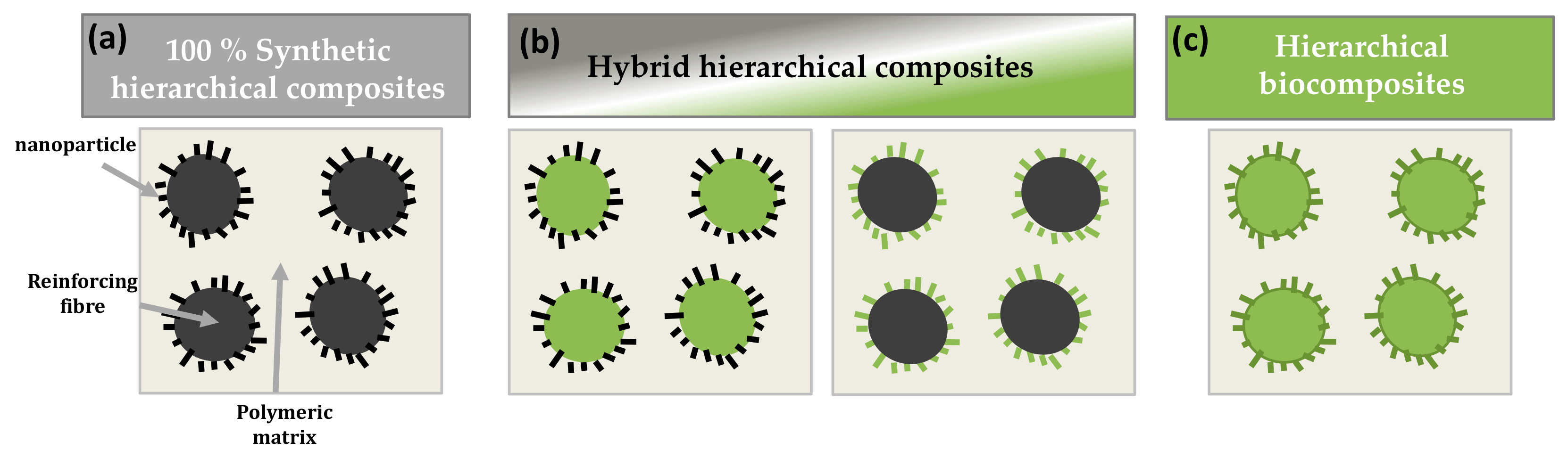
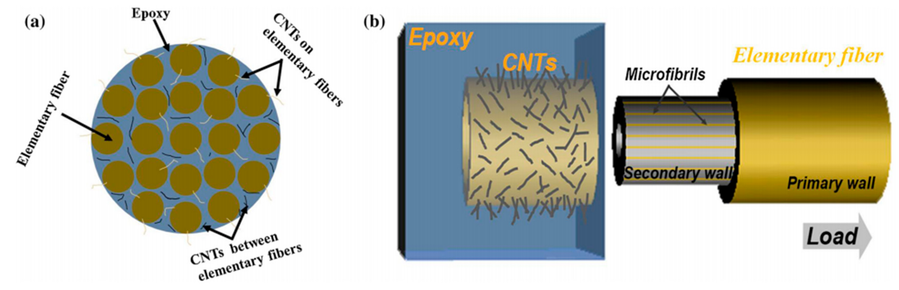
2.2. Towards the Conception of Hierarchical Composite Materials Using Nano-Objects
3. Hierarchical Interphase in Fully Synthetic and Hybrid Fibre Reinforced Composites
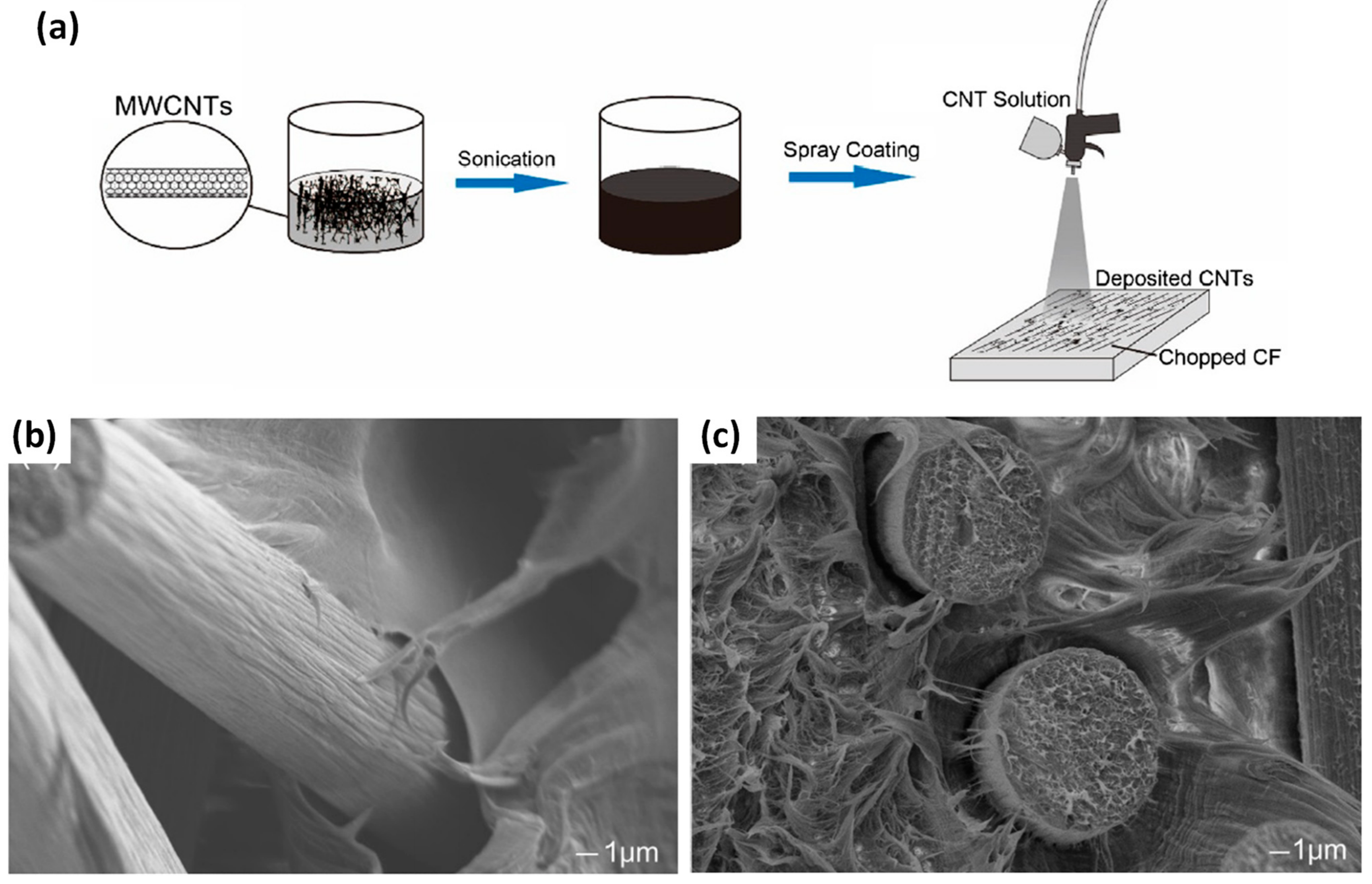
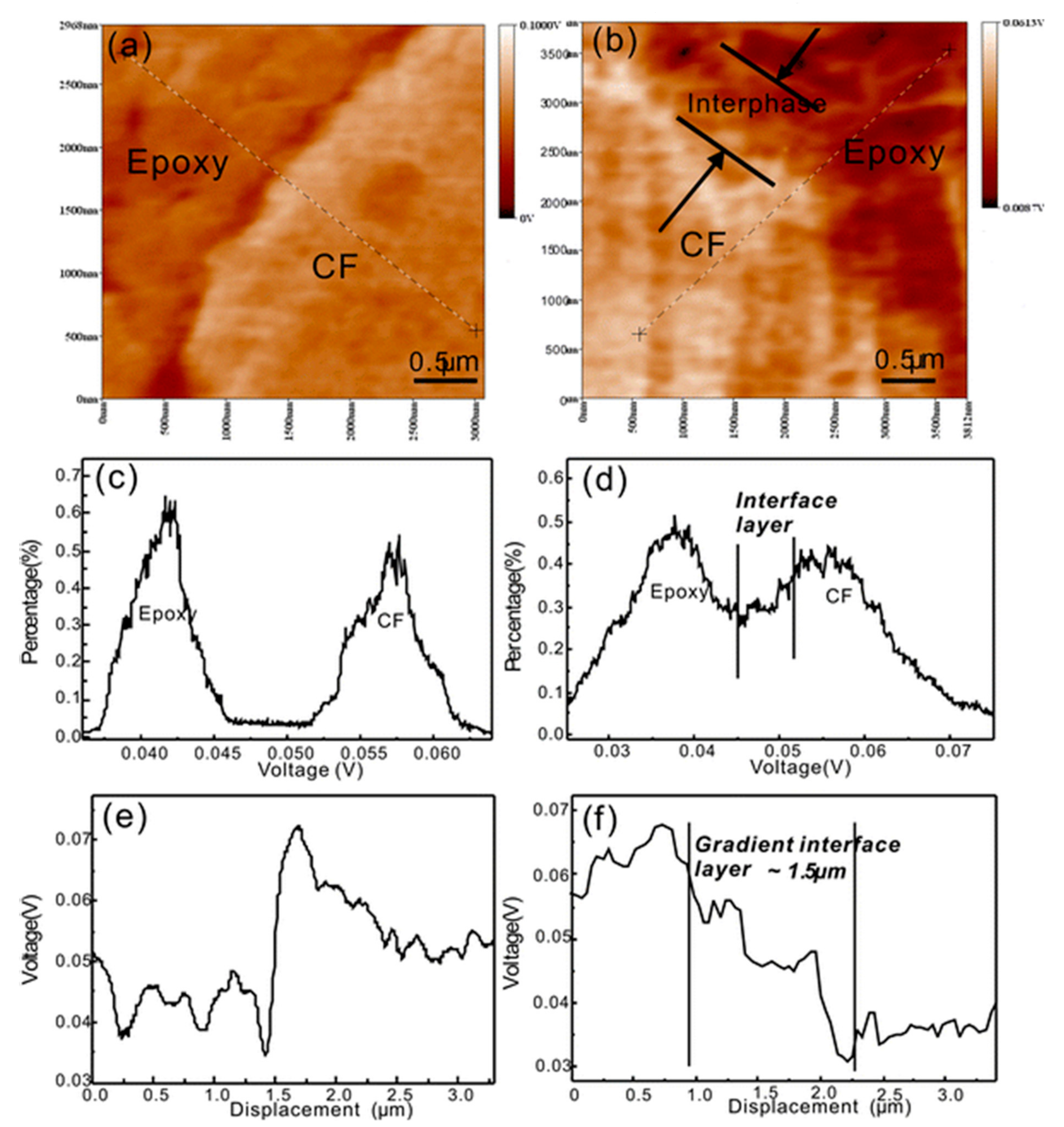
3.1. Fully Synthetic Hierarchical Fibre Reinforced Composites
3.2. Hybrid Hierarchical Fibre Reinforced Composites
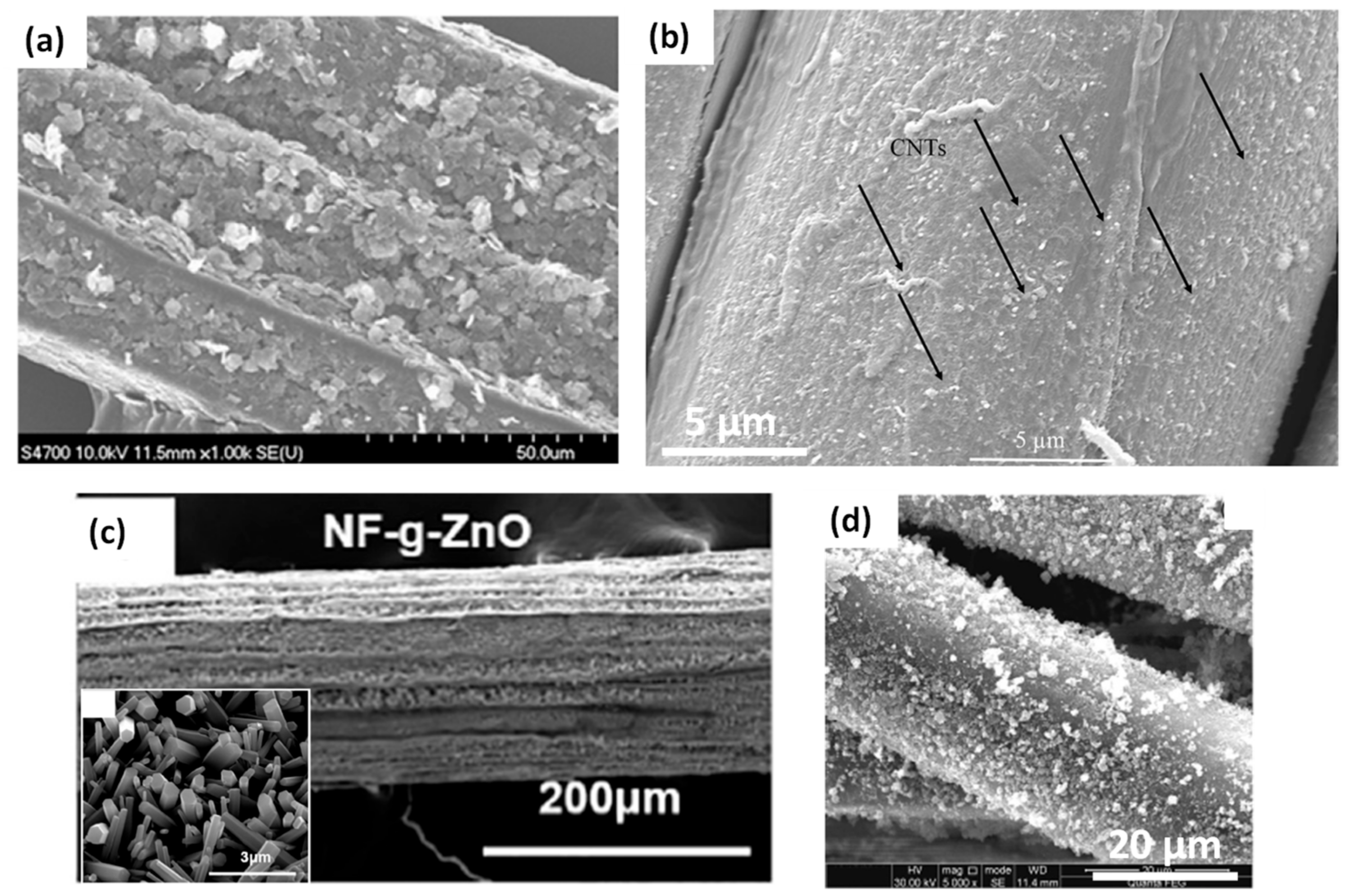
3.2.1. Hierarchical Natural Fibres Modified by Synthetic/Mineral Nanoparticles
3.2.2. Hierarchical Synthetic Fibres Modified by Bio-Based Nanoparticles
4. Hierarchical Interphase in Natural Fibre Reinforced Biocomposites
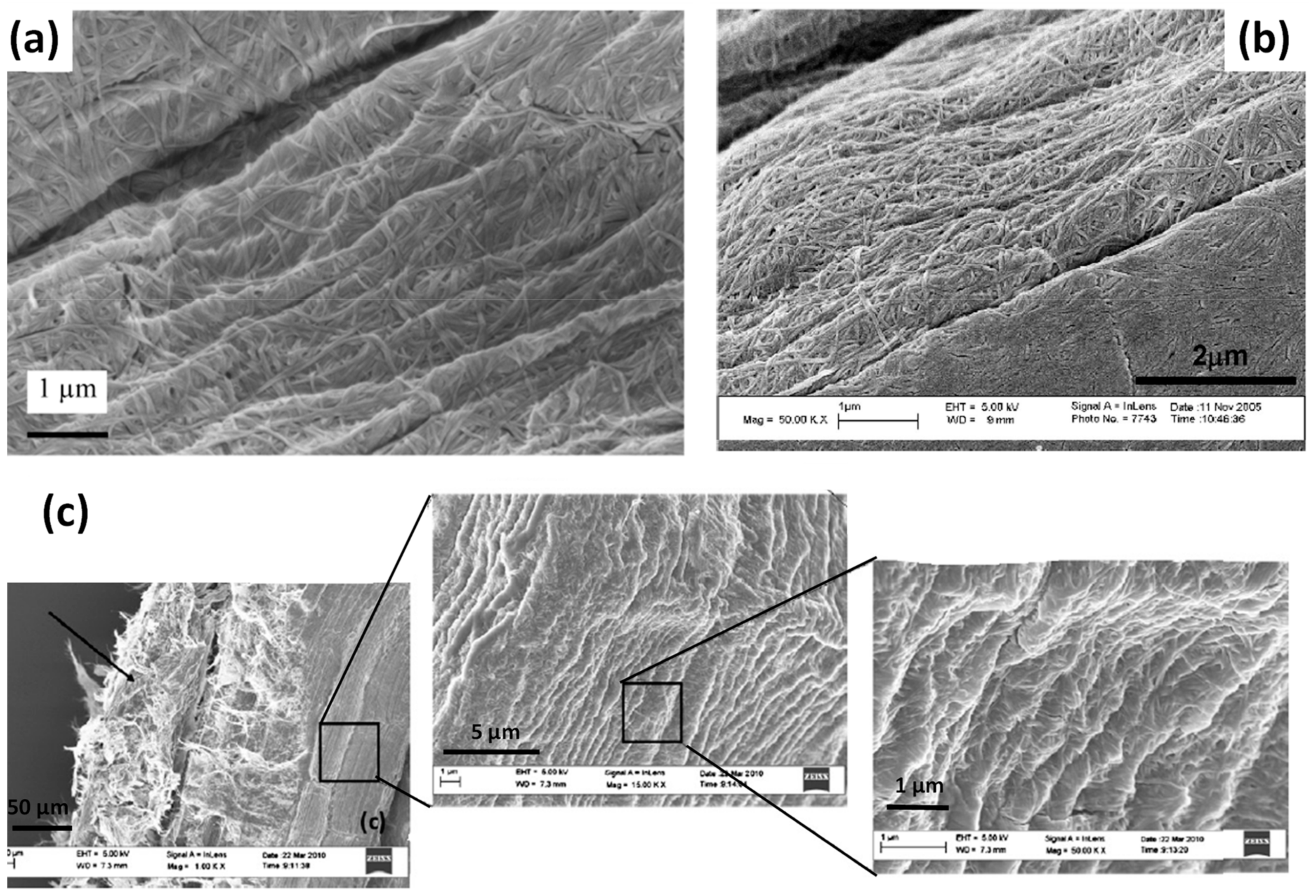
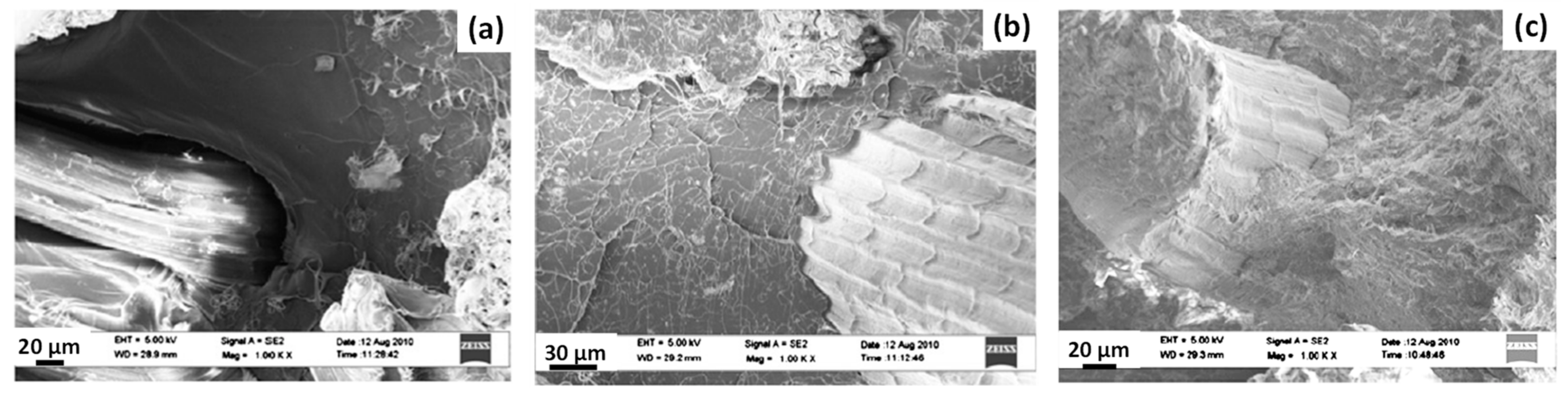
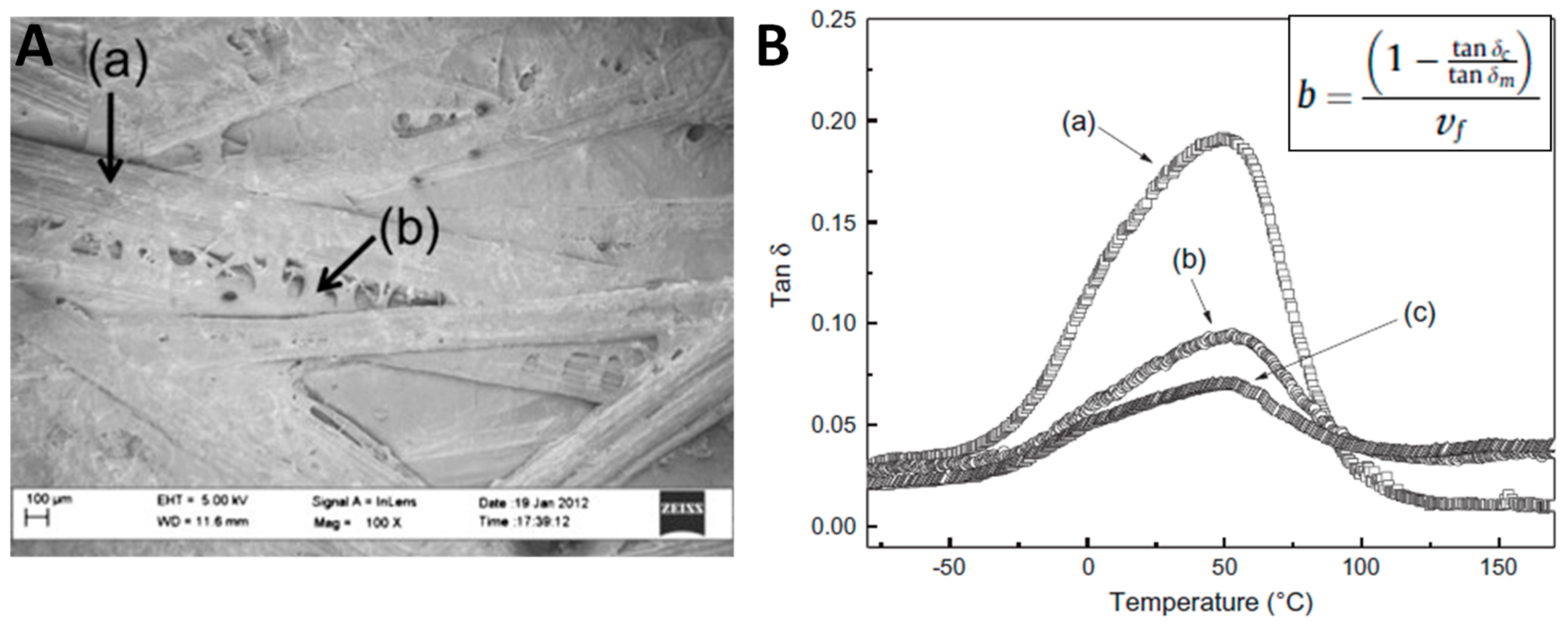
4.1. Hierarchical Natural Fibres Modified by Bacterial Cellulose
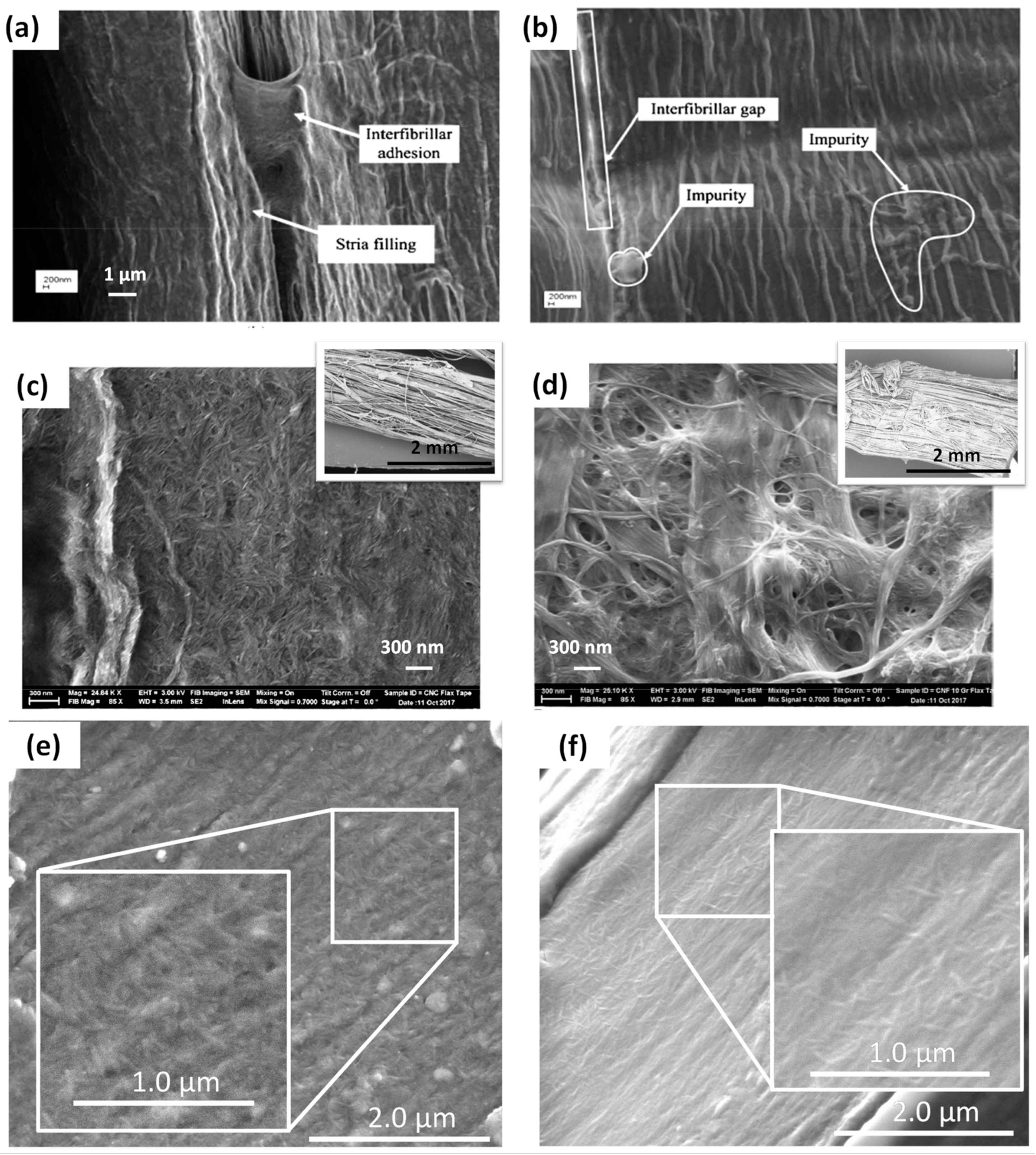
4.2. Hierarchical Natural Fibres Modified by Cellulose Nanocrystals (CNC) or Cellulose Nanofibrils (CNF)
5. Conclusions
Author Contributions
Funding
Institutional Review Board Statement
Informed Consent Statement
Data Availability Statement
Acknowledgments
Conflicts of Interest
References
- Barthelat, F.; Rabiei, R.; Dastjerdi, A.K. Multiscale Toughness Amplification in Natural Composites. Mrs Online Proc. Libr. Arch. 2012, 1420. [Google Scholar] [CrossRef]
- Libonati, F.; Buehler, M.J. Advanced Structural Materials by Bioinspiration. Adv. Eng. Mater. 2017, 19, 1600787. [Google Scholar] [CrossRef]
- Malakooti, M.H.; Zhou, Z.; Spears, J.H.; Shankwitz, T.J.; Sodano, H.A. Biomimetic Nanostructured Interfaces for Hierarchical Composites. Adv. Mater. Interfaces 2016, 3, 1500404. [Google Scholar] [CrossRef]
- Barthelat, F. Architectured Materials in Engineering and Biology: Fabrication, Structure, Mechanics and Performance. Int. Mater. Rev. 2015, 60, 413–430. [Google Scholar] [CrossRef]
- Wegst, U.G.K.; Bai, H.; Saiz, E.; Tomsia, A.P.; Ritchie, R.O. Bioinspired Structural Materials. Nat. Mater. 2015, 14, 23–36. [Google Scholar] [CrossRef]
- Studart, A.R. Biological and Bioinspired Composites with Spatially Tunable Heterogeneous Architectures. Adv. Funct. Mater. 2013, 23, 4423–4436. [Google Scholar] [CrossRef]
- Sanchez, C.; Arribart, H.; Giraud Guille, M.M. Biomimetism and Bioinspiration as Tools for the Design of Innovative Materials and Systems. Nat. Mater. 2005, 4, 277–288. [Google Scholar] [CrossRef]
- Li, M.; Miao, Y.; Zhai, X.; Yin, Y.; Zhang, Y.; Jian, Z.; Wang, X.; Sun, L.; Liu, Z. Preparation of and Research on Bioinspired Graphene Oxide/Nanocellulose/Polydopamine Ternary Artificial Nacre. Mater. Des. 2019, 181, 107961. [Google Scholar] [CrossRef]
- Duan, J.; Gong, S.; Gao, Y.; Xie, X.; Jiang, L.; Cheng, Q. Bioinspired Ternary Artificial Nacre Nanocomposites Based on Reduced Graphene Oxide and Nanofibrillar Cellulose. Acs Appl. Mater. Interfaces 2016, 8, 10545–10550. [Google Scholar] [CrossRef]
- Dimas, L.S.; Buehler, M.J. Influence of Geometry on Mechanical Properties of Bio-Inspired Silica-Based Hierarchical Materials. Bioinspir. Biomim. 2012, 7, 036024. [Google Scholar] [CrossRef]
- Du, J.; Niu, X.; Rahbar, N.; Soboyejo, W. Bio-Inspired Dental Multilayers: Effects of Layer Architecture on the Contact-Induced Deformation. Acta Biomater. 2013, 9, 5273–5279. [Google Scholar] [CrossRef]
- Opdenbosch, D.V.; Fritz-Popovski, G.; Paris, O.; Zollfrank, C. Silica Replication of the Hierarchical Structure of Wood with Nanometer Precision. J. Mater. Res. 2011, 26, 1193–1202. [Google Scholar] [CrossRef] [Green Version]
- Gupta, H.S.; Seto, J.; Wagermaier, W.; Zaslansky, P.; Boesecke, P.; Fratzl, P. Cooperative Deformation of Mineral and Collagen in Bone at the Nanoscale. Proc. Natl. Acad. Sci. USA 2006, 103, 17741–17746. [Google Scholar] [CrossRef] [Green Version]
- Weiner, S.; Wagner, H.D. The Material Bone: Structure-Mechanical Function Relations. Annu. Rev. Mater. Sci. 1998, 28, 271–298. [Google Scholar] [CrossRef]
- Müller, U.; Gindl-Altmutter, W.; Konnerth, J.; Maier, G.A.; Keckes, J. Synergy of Multi-Scale Toughening and Protective Mechanisms at Hierarchical Branch-Stem Interfaces. Sci. Rep. 2015, 5, 1–9. [Google Scholar] [CrossRef]
- Ehlert, G.J.; Galan, U.; Sodano, H.A. Role of Surface Chemistry in Adhesion between ZnO Nanowires and Carbon Fibers in Hybrid Composites. Acs Appl. Mater. Interfaces 2013, 5, 635–645. [Google Scholar] [CrossRef]
- Galan, U.; Lin, Y.; Ehlert, G.J.; Sodano, H.A. Effect of ZnO Nanowire Morphology on the Interfacial Strength of Nanowire Coated Carbon Fibers. Compos. Sci. Technol. 2011, 71, 946–954. [Google Scholar] [CrossRef]
- Karger-Kocsis, J.; Mahmood, H.; Pegoretti, A. Recent Advances in Fiber/Matrix Interphase Engineering for Polymer Composites. Prog. Mater. Sci. 2015, 73, 1–43. [Google Scholar] [CrossRef]
- Karger-Kocsis, J.; Mahmood, H.; Pegoretti, A. All-Carbon Multi-Scale and Hierarchical Fibers and Related Structural Composites: A Review. Compos. Sci. Technol. 2020, 186, 107932. [Google Scholar] [CrossRef]
- Sharma, M.; Gao, S.; Mäder, E.; Sharma, H.; Wei, L.Y.; Bijwe, J. Carbon Fiber Surfaces and Composite Interphases. Compos. Sci. Technol. 2014, 102, 35–50. [Google Scholar] [CrossRef]
- Chen, L.; Jin, H.; Xu, Z.; Li, J.; Guo, Q.; Shan, M.; Yang, C.; Wang, Z.; Mai, W.; Cheng, B. Role of a Gradient Interface Layer in Interfacial Enhancement of Carbon Fiber/Epoxy Hierarchical Composites. J. Mater. Sci. 2015, 50, 112–121. [Google Scholar] [CrossRef]
- Garcia, E.J.; Wardle, B.L.; John Hart, A.; Yamamoto, N. Fabrication and Multifunctional Properties of a Hybrid Laminate with Aligned Carbon Nanotubes Grown In Situ. Compos. Sci. Technol. 2008, 68, 2034–2041. [Google Scholar] [CrossRef]
- Kepple, K.L.; Sanborn, G.P.; Lacasse, P.A.; Gruenberg, K.M.; Ready, W.J. Improved Fracture Toughness of Carbon Fiber Composite Functionalized with Multi Walled Carbon Nanotubes. Carbon 2008, 46, 2026–2033. [Google Scholar] [CrossRef]
- Wang, W.X.; Takao, Y.; Matsubara, T.; Kim, H.S. Improvement of the Interlaminar Fracture Toughness of Composite Laminates by Whisker Reinforced Interlamination. Compos. Sci. Technol. 2002, 62, 767–774. [Google Scholar] [CrossRef]
- Idumah, C.I.; Hassan, A. Emerging Trends in Eco-Compliant, Synergistic, and Hybrid Assembling of Multifunctional Polymeric Bionanocomposites. Rev. Chem. Eng. 2016, 32, 305–361. [Google Scholar] [CrossRef]
- Saba, N.; Jawaid, M.; Asim, M. Recent advances in nanoclay/natural fibers hybrid composites. In Nanoclay Reinforced Polymer Composites: Natural Fibre/Nanoclay Hybrid Composites; Jawaid, M., Qaiss, A.e.K., Bouhfid, R., Eds.; Engineering Materials; Springer: Singapore, 2016; pp. 1–28. ISBN 978-981-10-0950-1. [Google Scholar]
- Lee, K.-Y.; Delille, A.; Bismarck, A. Greener surface treatments of natural fibres for the production of renewable composite materials. In Cellulose Fibers: Bio- and Nano-Polymer Composites; Kalia, S., Kaith, B.S., Kaur, I., Eds.; Springer: Berlin/Heidelberg, Germany, 2011; pp. 155–178. ISBN 978-3-642-17369-1. [Google Scholar]
- Pommet, M.; Juntaro, J.; Heng, J.Y.Y.; Mantalaris, A.; Lee, A.F.; Wilson, K.; Kalinka, G.; Shaffer, M.S.P.; Bismarck, A. Surface Modification of Natural Fibers Using Bacteria: Depositing Bacterial Cellulose onto Natural Fibers To Create Hierarchical Fiber Reinforced Nanocomposites. Biomacromolecules 2008, 9, 1643–1651. [Google Scholar] [CrossRef] [PubMed] [Green Version]
- Dai, D.; Fan, M. Green Modification of Natural Fibres with Nanocellulose. Rsc. Adv. 2013, 3, 4659. [Google Scholar] [CrossRef]
- Rho, J.-Y.; Kuhn-Spearing, L.; Zioupos, P. Mechanical Properties and the Hierarchical Structure of Bone. Med. Eng. Phys. 1998, 20, 92–102. [Google Scholar] [CrossRef]
- Weiner, S.; Traub, W.; Wagner, H.D. Lamellar Bone: Structure—Function Relations. J. Struct. Biol. 1999, 126, 241–255. [Google Scholar] [CrossRef]
- Kamat, S.; Su, X.; Ballarini, R.; Heuer, A.H. Structural Basis for the Fracture Toughness of the Shell of the Conch Strombus Gigas. Nature 2000, 405, 1036–1040. [Google Scholar] [CrossRef] [PubMed]
- Jackson, A.P.; Vincent, J.F.V.; Turner, R.M.; Alexander, R.M. The Mechanical Design of Nacre. Proc. R. Soc. Lond. Ser. B Biol. Sci. 1988, 234, 415–440. [Google Scholar] [CrossRef]
- Gershon, A.L.; Bruck, H.A.; Xu, S.; Sutton, M.A.; Tiwari, V. Multiscale Mechanical and Structural Characterizations of Palmetto Wood for Bio-Inspired Hierarchically Structured Polymer Composites. Mater. Sci. Eng. C 2010, 30, 235–244. [Google Scholar] [CrossRef] [PubMed]
- Landis, W.J. The Strength of a Calcified Tissue Depends in Part on the Molecular Structure and Organization of Its Constituent Mineral Crystals in Their Organic Matrix. Bone 1995, 16, 533–544. [Google Scholar] [CrossRef]
- Roschger, P.; Grabner, B.M.; Rinnerthaler, S.; Tesch, W.; Kneissel, M.; Berzlanovich, A.; Klaushofer, K.; Fratzl, P. Structural Development of the Mineralized Tissue in the Human L4 Vertebral Body. J. Struct. Biol. 2001, 136, 126–136. [Google Scholar] [CrossRef]
- Launey, M.E.; Buehler, M.J.; Ritchie, R.O. On the Mechanistic Origins of Toughness in Bone. Annu. Rev. Mater. Res. 2010, 40, 25–53. [Google Scholar] [CrossRef] [Green Version]
- Peterlik, H.; Roschger, P.; Klaushofer, K.; Fratzl, P. From Brittle to Ductile Fracture of Bone. Nat. Mater. 2006, 5, 52–55. [Google Scholar] [CrossRef]
- Nalla, R.K.; Kruzic, J.J.; Kinney, J.H.; Ritchie, R.O. Mechanistic Aspects of Fracture and R-Curve Behavior in Human Cortical Bone. Biomaterials 2005, 26, 217–231. [Google Scholar] [CrossRef]
- Zimmermann, E.A.; Schaible, E.; Gludovatz, B.; Schmidt, F.N.; Riedel, C.; Krause, M.; Vettorazzi, E.; Acevedo, C.; Hahn, M.; Püschel, K.; et al. Intrinsic Mechanical Behavior of Femoral Cortical Bone in Young, Osteoporotic and Bisphosphonate-Treated Individuals in Low- and High Energy Fracture Conditions. Sci. Rep. 2016, 6, 21072. [Google Scholar] [CrossRef] [Green Version]
- Gao, H.; Ji, B.; Jager, I.L.; Arzt, E.; Fratzl, P. Materials Become Insensitive to Flaws at Nanoscale: Lessons from Nature. Proc. Natl. Acad. Sci. USA 2003, 100, 5597–5600. [Google Scholar] [CrossRef] [Green Version]
- Menig, R.; Meyers, M.H.; Meyers, M.A.; Vecchio, K.S. Quasi-Static and Dynamic Mechanical Response of Haliotis Rufescens (Abalone) Shells. Acta Mater. 2000, 48, 2383–2398. [Google Scholar] [CrossRef]
- Wang, R.Z.; Suo, Z.; Evans, A.G.; Yao, N.; Aksay, I.A. Deformation Mechanisms in Nacre. J. Mater. Res. 2001, 16, 2485–2493. [Google Scholar] [CrossRef]
- Song, F.; Bai, Y.L. Effects of Nanostructures on the Fracture Strength of the Interfaces in Nacre. J. Mater. Res. 2003, 18, 1741–1744. [Google Scholar] [CrossRef] [Green Version]
- Dufresne, A. Nanocellulose: From Nature to High Performance Tailored Materials; Walter de Gruyter GmbH & Co KG: Berlin, Germany, 2017; ISBN 978-3-11-048041-2. [Google Scholar]
- Meyers, M.A.; Chen, P.-Y.; Lin, A.Y.-M.; Seki, Y. Biological Materials: Structure and Mechanical Properties. Prog. Mater. Sci. 2008, 53, 1–206. [Google Scholar] [CrossRef] [Green Version]
- Le Moigne, N.; Otazaghine, B.; Corn, S.; Angellier-Coussy, H.; Bergeret, A. Surfaces and Interfaces in Natural Fibre Reinforced Composites; SpringerBriefs in Molecular Science; Springer International Publishing: Cham, Switzerland, 2018; ISBN 978-3-319-71409-7. [Google Scholar]
- Ritchie, R.O. The Conflicts between Strength and Toughness. Nat. Mater. 2011, 10, 817–822. [Google Scholar] [CrossRef]
- Mann, S. Biomineralization: Principles and Concepts in Bioinorganic Materials Chemistry; Oxford University Press: Oxford, UK, 2001; ISBN 978-0-19-850882-3. [Google Scholar]
- Zabihi, O.; Ahmadi, M.; Li, Q.; Shafei, S.; Huson, M.G.; Naebe, M. Carbon Fibre Surface Modification Using Functionalized Nanoclay: A Hierarchical Interphase for Fibre-Reinforced Polymer Composites. Compos. Sci. Technol. 2017, 148, 49–58. [Google Scholar] [CrossRef]
- Subramaniyan, A.K.; Sun, C.T. Interlaminar Fracture Behavior of Nanoclay Reinforced Glass Fiber Composites. J. Compos. Mater. 2008, 42, 2111–2122. [Google Scholar] [CrossRef]
- Gao, S.; Zhuang, R.-C.; Zhang, J.; Liu, J.-W.; Mäder, E. Glass Fibers with Carbon Nanotube Networks as Multifunctional Sensors. Adv. Funct. Mater. 2010, 20, 1885–1893. [Google Scholar] [CrossRef]
- Tansan, M. Tailoring Interfacial Interactions in Fiber Reinforced Polymeric Composites by the Electrospray Deposition of Waterborne Carbon Nanotubes. Ph.D. Thesis, Sabanci University, Istanbul, Turkey, May 2019. [Google Scholar]
- Zakaria, M.R.; Akil, H.M.; Omar, M.F.; Kudus, M.H.A.; Sabri, F.N.A.M.; Abdullah, M.M.A.B. Woven Carbon Fiber Epoxy Composite Laminates Reinforced With Carbon Nanotube Interlayer Using Electrospray Deposition Method. Compos. Part C Open Access 2020, 3, 100075. [Google Scholar] [CrossRef]
- Mayela Garcia Montes, S. Synthesis of Carbon Nanotubes on Surface of Recovered Carbon Fibers by Chemical Vapor Deposition, as a Sizing Process to Obtain a Hybrid Material. Ph.D. Thesis, Autonomous University of Nuevo Leon, San Nicolas de los Garza, Mexico, 2017. [Google Scholar]
- Ehlert, G.J.; Sodano, H.A. Zinc Oxide Nanowire Interphase for Enhanced Interfacial Strength in Lightweight Polymer Fiber Composites. Acs Appl. Mater. Interfaces 2009, 1, 1827–1833. [Google Scholar] [CrossRef]
- Qian, H.; Bismarck, A.; Greenhalgh, E.S.; Shaffer, M.S.P. Carbon Nanotube Grafted Carbon Fibres: A Study of Wetting and Fibre Fragmentation. Compos. Part A Appl. Sci. Manuf. 2010, 41, 1107–1114. [Google Scholar] [CrossRef] [Green Version]
- Hu, C.; Liao, X.; Qin, Q.-H.; Wang, G. The Fabrication and Characterization of High Density Polyethylene Composites Reinforced by Carbon Nanotube Coated Carbon Fibers. Compos. Part A Appl. Sci. Manuf. 2019, 121, 149–156. [Google Scholar] [CrossRef]
- Romanov, V.; Lomov, S.V.; Verpoest, I.; Gorbatikh, L. Inter-Fiber Stresses in Composites with Carbon Nanotube Grafted and Coated Fibers. Compos. Sci. Technol. 2015, 114, 79–86. [Google Scholar] [CrossRef]
- Romanov, V.S.; Lomov, S.V.; Verpoest, I.; Gorbatikh, L. Modelling Evidence of Stress Concentration Mitigation at the Micro-Scale in Polymer Composites by the Addition of Carbon Nanotubes. Carbon 2015, 82, 184–194. [Google Scholar] [CrossRef]
- Han, G.; Lei, Y.; Wu, Q.; Kojima, Y.; Suzuki, S. Bamboo-Fiber Filled High Density Polyethylene Composites: Effect of Coupling Treatment and Nanoclay. J. Polym. Environ. 2008, 16, 123–130. [Google Scholar] [CrossRef]
- Najafi, A.; Kord, B.; Abdi, A.; Ranaee, S. The Impact of the Nature of Nanoclay on Physical and Mechanical Properties of Polypropylene/Reed Flour Nanocomposites. J. Thermoplast. Compos. Mater. 2011. [Google Scholar] [CrossRef]
- Rozyanty, A.R.; Rozman, H.D.; Tay, G.S. Ultra-Violet Radiationcured Composites Based on Unsaturated Polyester Resin Filled with MMT and Kenaf Bast Fiber. Adv. Mater. Res. 2011, 264–265, 712–718. [Google Scholar] [CrossRef]
- Han, S.O.; Karevan, M.; Bhuiyan, M.A.; Park, J.H.; Kalaitzidou, K. Effect of Exfoliated Graphite Nanoplatelets on the Mechanical and Viscoelastic Properties of Poly(Lactic Acid) Biocomposites Reinforced with Kenaf Fibers. J. Mater. Sci. 2012, 47, 3535–3543. [Google Scholar] [CrossRef]
- Li, Y.; Chen, C.; Xu, J.; Zhang, Z.; Yuan, B.; Huang, X. Improved Mechanical Properties of Carbon Nanotubes-Coated Flax Fiber Reinforced Composites. J. Mater. Sci. 2015, 50, 1117–1128. [Google Scholar] [CrossRef]
- Yang, C.; Han, R.; Nie, M.; Wang, Q. Interfacial Reinforcement Mechanism in Poly(Lactic Acid)/Natural Fiber Biocomposites Featuring ZnO Nanowires at the Interface. Mater. Des. 2020, 186, 108332. [Google Scholar] [CrossRef]
- Wang, H.; Xian, G.; Li, H. Grafting of Nano-TiO2 onto Flax Fibers and the Enhancement of the Mechanical Properties of the Flax Fiber and Flax Fiber/Epoxy Composite. Compos. Part A Appl. Sci. Manuf. 2015, 76, 172–180. [Google Scholar] [CrossRef]
- Taha, I.M.; Ziegmann, G. Potential of Sisal Reinforced Biodegradable Polylactic Acid and Polyvinyl Alcohol Composites. Available online: https://www.scientific.net/KEM.425.167 (accessed on 21 February 2021).
- Sbardella, F.; Lilli, M.; Seghini, M.C.; Bavasso, I.; Touchard, F.; Chocinski-Arnault, L.; Rivilla, I.; Tirillò, J.; Sarasini, F. Interface Tailoring between Flax Yarns and Epoxy Matrix by ZnO Nanorods. Compos. Part A Appl. Sci. Manuf. 2021, 140, 106156. [Google Scholar] [CrossRef]
- Ovalle-Serrano, S.A.; Carrillo, V.S.; Blanco-Tirado, C.; Hinestroza, J.P.; Combariza, M.Y. Controlled Synthesis of ZnO Particles on the Surface of Natural Cellulosic Fibers: Effect of Concentration, Heating and Sonication. Cellulose 2015, 22, 1841–1852. [Google Scholar] [CrossRef]
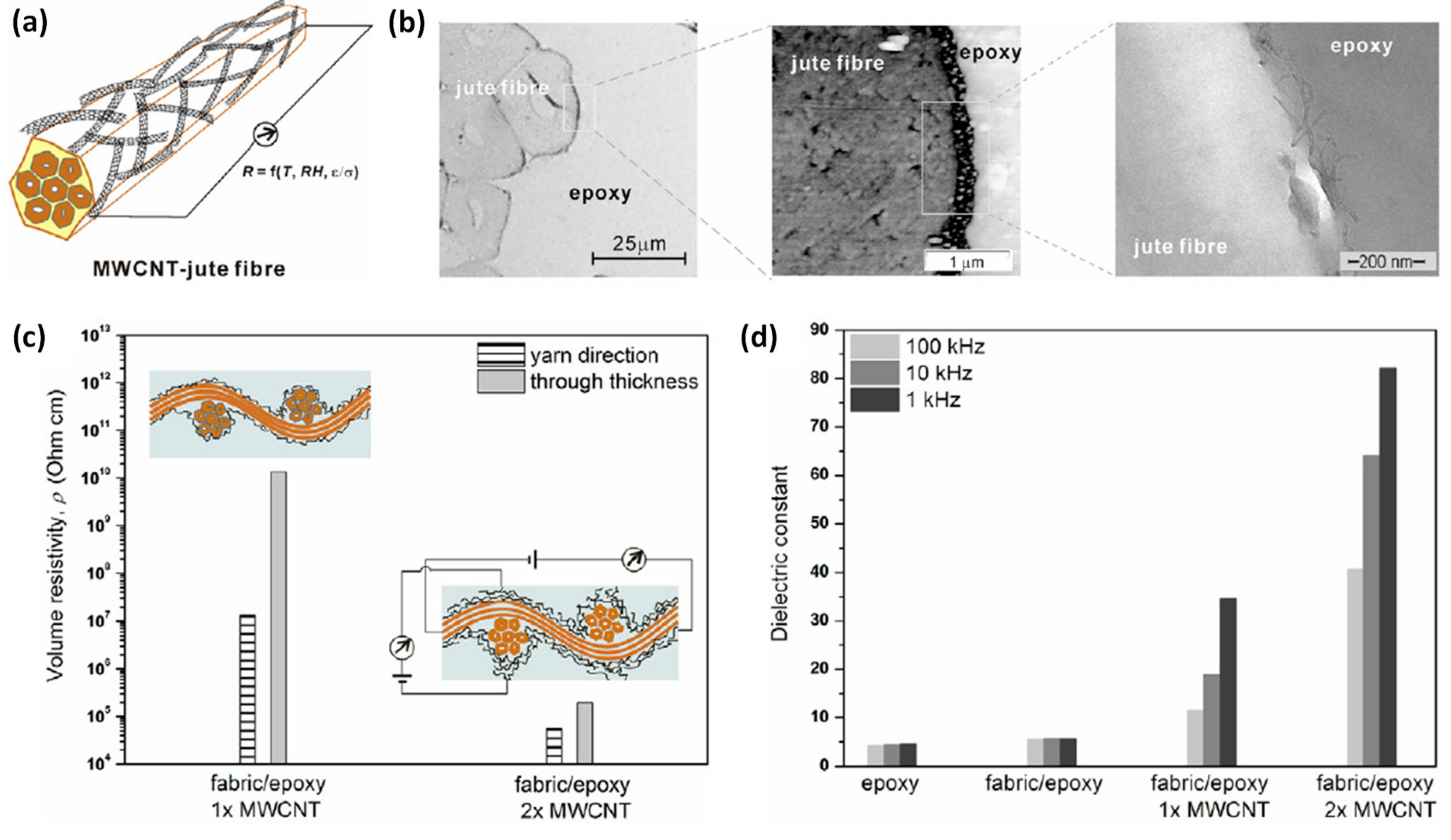
- Zhuang, R.-C.; Doan, T.T.L.; Liu, J.-W.; Zhang, J.; Gao, S.-L.; Mäder, E. Multi-Functional Multi-Walled Carbon Nanotube-Jute Fibres and Composites. Carbon 2011, 49, 2683–2692. [Google Scholar] [CrossRef]
- Cheng, Q.; Wang, S.; Harper, D.P. Effects of Process and Source on Elastic Modulus of Single Cellulose Fibrils Evaluated by Atomic Force Microscopy. Compos. Part A Appl. Sci. Manuf. 2009, 40, 583–588. [Google Scholar] [CrossRef]
- Foster, E.J.; Moon, R.J.; Agarwal, U.P.; Bortner, M.J.; Bras, J.; Camarero-Espinosa, S.; Chan, K.J.; Clift, M.J.D.; Cranston, E.D.; Eichhorn, S.J.; et al. Current Characterization Methods for Cellulose Nanomaterials. Chem. Soc. Rev. 2018, 47, 2609–2679. [Google Scholar] [CrossRef] [PubMed] [Green Version]
- Dufresne, A. Nanocellulose: A New Ageless Bionanomaterial. Mater. Today 2013, 16, 220–227. [Google Scholar] [CrossRef]
- Iguchi, M.; Yamanaka, S.; Budhiono, A. Review Bacterial Cellulose—A Masterpiece of Nature’s Arts. J. Mater. Sci. 2000, 35, 261–270. [Google Scholar] [CrossRef]
- Lee, K.-Y.; Buldum, G.; Mantalaris, A.; Bismarck, A. More Than Meets the Eye in Bacterial Cellulose: Biosynthesis, Bioprocessing, and Applications in Advanced Fiber Composites. Macromol. Biosci. 2014, 14, 10–32. [Google Scholar] [CrossRef] [PubMed] [Green Version]
- Czaja, W.; Romanovicz, D.; Brown, R.M. Structural Investigations of Microbial Cellulose Produced in Stationary and Agitated Culture. Cellulose 2004, 11, 403–411. [Google Scholar] [CrossRef]
- Guhados, G.; Wan, W.; Hutter, J.L. Measurement of the Elastic Modulus of Single Bacterial Cellulose Fibers Using Atomic Force Microscopy. Langmuir 2005, 21, 6642–6646. [Google Scholar] [CrossRef] [PubMed]
- Chen, Y.; Zhou, X.; Yin, X.; Lin, Q.; Zhu, M. A Novel Route to Modify the Interface of Glass Fiber-Reinforced Epoxy Resin Composite via Bacterial Cellulose. Int. J. Polym. Mater. Polym. Biomater. 2014, 63, 221–227. [Google Scholar] [CrossRef]
- Asadi, A.; Miller, M.; Moon, R.J.; Kalaitzidou, K. Improving the Interfacial and Mechanical Properties of Short Glass Fiber/Epoxy Composites by Coating the Glass Fibers with Cellulose Nanocrystals. Express Polym. Lett. 2016, 10, 587–597. [Google Scholar] [CrossRef]
- Shariatnia, S.; Kumar, A.V.; Kaynan, O.; Asadi, A. Hybrid Cellulose Nanocrystal-Bonded Carbon Nanotubes/Carbon Fiber Polymer Composites for Structural Applications. Acs Appl. Nano Mater. 2020, 3, 5421–5436. [Google Scholar] [CrossRef]
- Kumar, A.; Shariatnia, S.; Asadi, A. Cellulose Nanocrystals Assisted Process to Integrate Carbon Nanotubes in CFRP Composites. In Proceedings of the AIAA Scitech 2020 Forum, Orlando, FL, USA, 6–10 January 2020; American Institute of Aeronautics and Astronautics: Reston, VA, USA, 2020. [Google Scholar]
- Acera Fernández, J.; Le Moigne, N.; Caro-Bretelle, A.S.; El Hage, R.; Le Duc, A.; Lozachmeur, M.; Bono, P.; Bergeret, A. Role of Flax Cell Wall Components on the Microstructure and Transverse Mechanical Behaviour of Flax Fabrics Reinforced Epoxy Biocomposites. Ind. Crop. Prod. 2016, 85, 93–108. [Google Scholar] [CrossRef]
- Juntaro, J.; Pommet, M.; Mantalaris, A.; Shaffer, M.; Bismarck, A. Nanocellulose Enhanced Interfaces in Truly Green Unidirectional Fibre Reinforced Composites. Compos. Interfaces 2007, 14, 753–762. [Google Scholar] [CrossRef]
- Juntaro, J.; Pommet, M.; Kalinka, G.; Mantalaris, A.; Shaffer, M.S.P.; Bismarck, A. Creating Hierarchical Structures in Renewable Composites by Attaching Bacterial Cellulose onto Sisal Fibers. Adv. Mater. 2008, 20, 3122–3126. [Google Scholar] [CrossRef]
- Lee, K.-Y.; Bharadia, P.; Blaker, J.J.; Bismarck, A. Short Sisal Fibre Reinforced Bacterial Cellulose Polylactide Nanocomposites Using Hairy Sisal Fibres as Reinforcement. Compos. Part A Appl. Sci. Manuf. 2012, 43, 2065–2074. [Google Scholar] [CrossRef] [Green Version]
- Lee, K.-Y.; Ho, K.K.C.; Schlufter, K.; Bismarck, A. Hierarchical Composites Reinforced with Robust Short Sisal Fibre Preforms Utilising Bacterial Cellulose as Binder. Compos. Sci. Technol. 2012, 72, 1479–1486. [Google Scholar] [CrossRef] [Green Version]
- Dong, S.; Gauvin, R. Application of Dynamic Mechanical Analysis for the Study of the Interfacial Region in Carbon Fiber/Epoxy Composite Materials. Polym. Compos. 1993, 14, 414–420. [Google Scholar] [CrossRef]
- Le Moigne, N.; Longerey, M.; Taulemesse, J.-M.; Bénézet, J.-C.; Bergeret, A. Study of the Interface in Natural Fibres Reinforced Poly(Lactic Acid) Biocomposites Modified by Optimized Organosilane Treatments. Ind. Crop. Prod. 2014, 52, 481–494. [Google Scholar] [CrossRef]
- Ghasemi, S.; Tajvidi, M.; Bousfield, D.W.; Gardner, D.J. Reinforcement of Natural Fiber Yarns by Cellulose Nanomaterials: A Multi-Scale Study. Ind. Crop. Prod. 2018, 111, 471–481. [Google Scholar] [CrossRef]
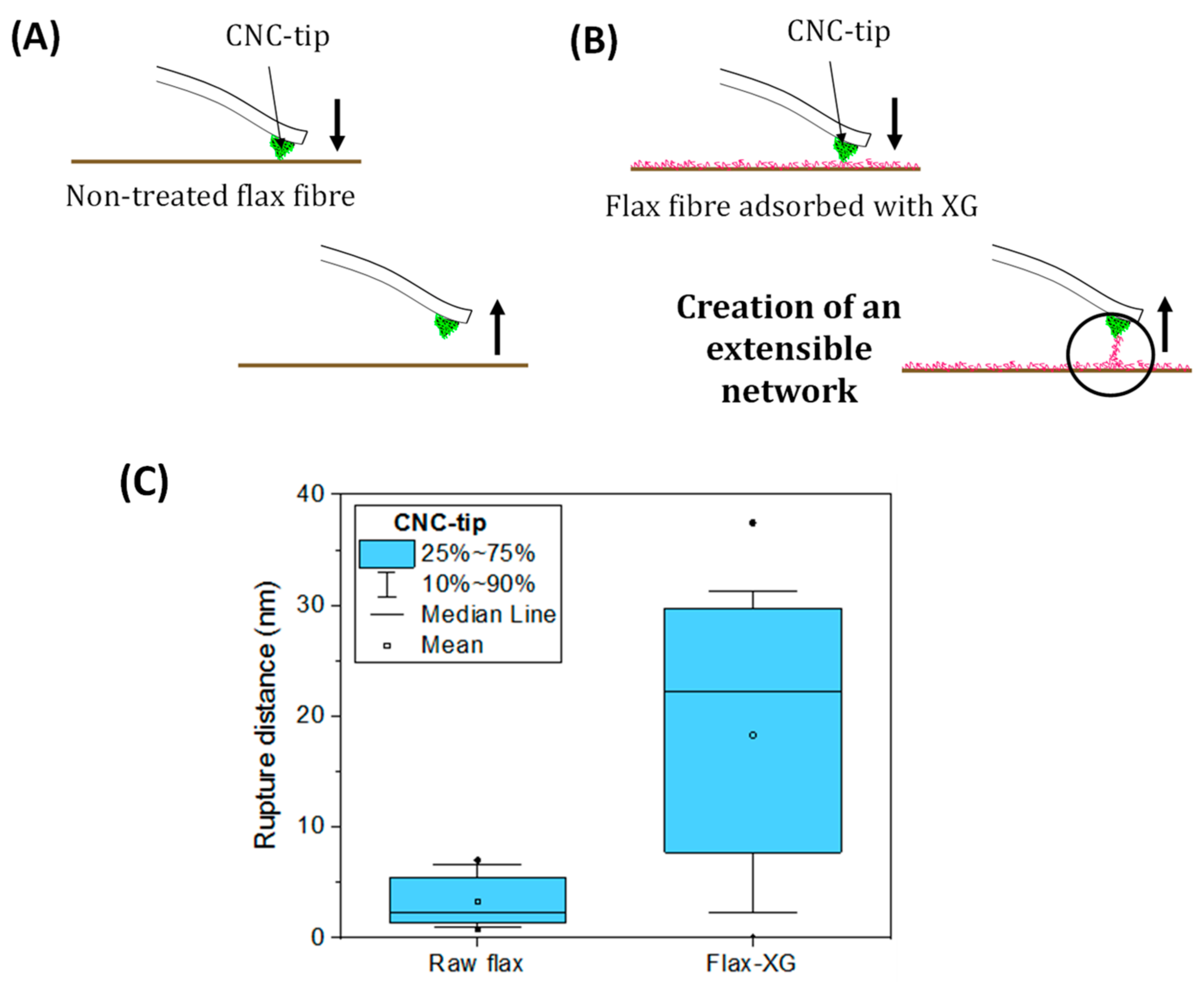
- Doineau, E.; Bauer, G.; Ensenlaz, L.; Novales, B.; Sillard, C.; Bénézet, J.-C.; Bras, J.; Cathala, B.; Le Moigne, N. Adsorption of Xyloglucan and Cellulose Nanocrystals on Natural Fibres for the Creation of Hierarchically Structured Fibres. Carbohydr. Polym. 2020, 248, 116713. [Google Scholar] [CrossRef] [PubMed]
- Park, Y.B.; Cosgrove, D.J. Xyloglucan and Its Interactions with Other Components of the Growing Cell Wall. Plant Cell Physiol. 2015, 56, 180–194. [Google Scholar] [CrossRef] [PubMed] [Green Version]
- Benselfelt, T.; Cranston, E.D.; Ondaral, S.; Johansson, E.; Brumer, H.; Rutland, M.W.; Wågberg, L. Adsorption of Xyloglucan onto Cellulose Surfaces of Different Morphologies: An Entropy-Driven Process. Biomacromolecules 2016, 17, 2801–2811. [Google Scholar] [CrossRef]
- Doineau, E.; Coqueugniot, G.; Pucci, M.F.; Caro, A.-S.; Cathala, B.; Bénézet, J.-C.; Bras, J.; Le Moigne, N. Hierarchical Thermoplastic Biocomposites Reinforced with Flax Fibres Modified by Xyloglucan and Cellulose Nanocrystals. Carbohydr. Polym. 2021, 254, 117403. [Google Scholar] [CrossRef] [PubMed]


| Matrix/Fibre | Nano-Objects, Treatment Method | Properties | Ref. | |||
|---|---|---|---|---|---|---|
| Surface Properties | Wettability | IFSS (MPa) | Composite Microstructure and Properties | |||
| PMMA/IM7 carbon fibres | CNTs, CVD method (growth) ▼1 Drawback: drop by 15–17% of CNTs-carbon fibre strength | Surface area: ▲1 141% | 27.4° → 21.6° Drop-on-fibre technique | ▲ 12.5 MPa ± 0.2 → 15.8 MPa ± 0.4 SFFT technique | – | Qian et al., 2010 [57] |
| Epoxy resin/GTMAC modified carbon fibres | APTES functionalized nanoclays, cations exchange method | Roughness: 64 nm → 103 nm Coefficient of friction: ▲ 11% Surface area: ▲ 5% | ~42° → ~25° Drop-on-fibre technique | ▲ 24.8 MPa ± 3.5 → 32.8 MPa ± 4.5 SFFT technique | Fibres embedded tightly by matrix, crack deviation with nanoclays (based on failure surface observations) | Zabihi et al., 2017 [50] |
| Epoxy resin/carbon fibres | Graphene nanosheets (EG), liquid phase deposition | Irregular and micro-scale EG attached along the fibre axial direction | – | – | Transition phase from matrix to fibres with local stiffening (AFM, force modulation mode) ILSS: ▲ 28% Flexural modulus and strength: ▲ 5% and ▲ 31% (with 1.0 wt% EG in evaporate solvent) | Chen et al., 2015 [21] |
| Epoxy resin/carboxylic acid modified aramid fibres | ZnO nanowires, deposition method (dip-coating in a seed suspension and growth on fibre) | Presence of large crystalline ZnO nanowires on fibres, relatively uniform in length and diameter | – | ▲ 11.0 MPa ± 2.5 → 16.8 MPa ± 2.8 SFFT technique | – | Ehlert and Sodano 2009 [56] |
| Matrix/Fibre | Nano-Objects, Treatment Method | Properties | Ref. | |||
|---|---|---|---|---|---|---|
| Surface Properties | Wettability | IFSS (MPa) | Composite Microstructure and Properties | |||
| Natural Fibres + Synthetic/Mineral Nano-Objects | ||||||
| PLA/Kenaf fibres | Exfoliated graphite nanoplatelets (xGnP), adsorption into acetone → excess of xGnP, not adsorbed on fibre surface, dispersed within PLA during compounding | physically-adsorbed multi-layers of xGnP on fibre surfaces | – | – | Flexural modulus: ▲1 23% (with 40 wt% kenaf and 5 wt% xGnP added in acetone) ▼1 Flexural strength with the addition of xGnP (decrease of the interfacial adhesion) | Han et al., 2012 [64] |
| PLA /sisal fibres | ZnO nanowires, hydrothermal deposition method (dip-coating in a seed suspension and growth on fibre) | 6 dip-coating cycles: nanowires relatively uniform with typical diameter of about 100 nm and length of ~2 µm | – | ▲ 2.8 MPa → 7.2 MPa Single fibre pull-out technique ▼Drawback: very low IFSS values compared to literature | – | Yang et al., 2020 [66] |
| Epoxy resin/flax yarns | Carboxyl-functionalised CNTs, spray-drying process (better results for 1 wt% CNTs suspension concentration) | Uniformly dispersed and randomly oriented CNTs | – | ▲ 43.7 MPa → 55.0 MPa Single yarn pull-out technique ▼Drawback: no information on test settings | ILSS: ▲ 20% | Li et al., 2015 [65] |
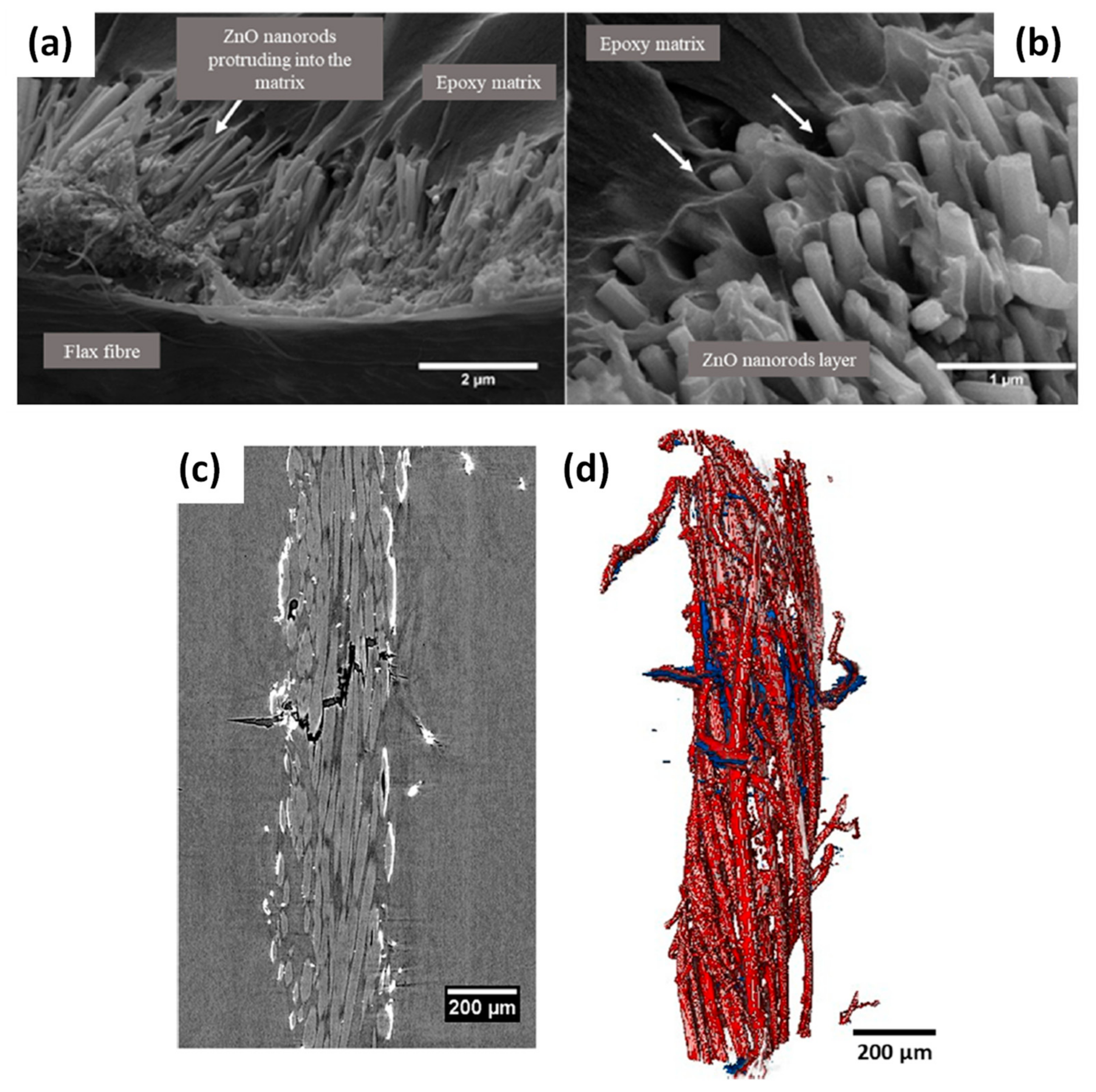
| Epoxy resin/flax yarns | ZnO nanorods, hydrothermal deposition method (dip-coating in a seed suspension and growth on fibre) | Highly oriented hexagonal ZnO nanorods | – | ▼ 19.3 MPa → 12.7 MPa SFFT technique (single yarn) | Fracture surfaces: improved mechanical interlocking 3D reconstruction of fibre yarns: matrix cracks and debonding between yarns and epoxy matrix | Sbardella et al., 2021 [69] |
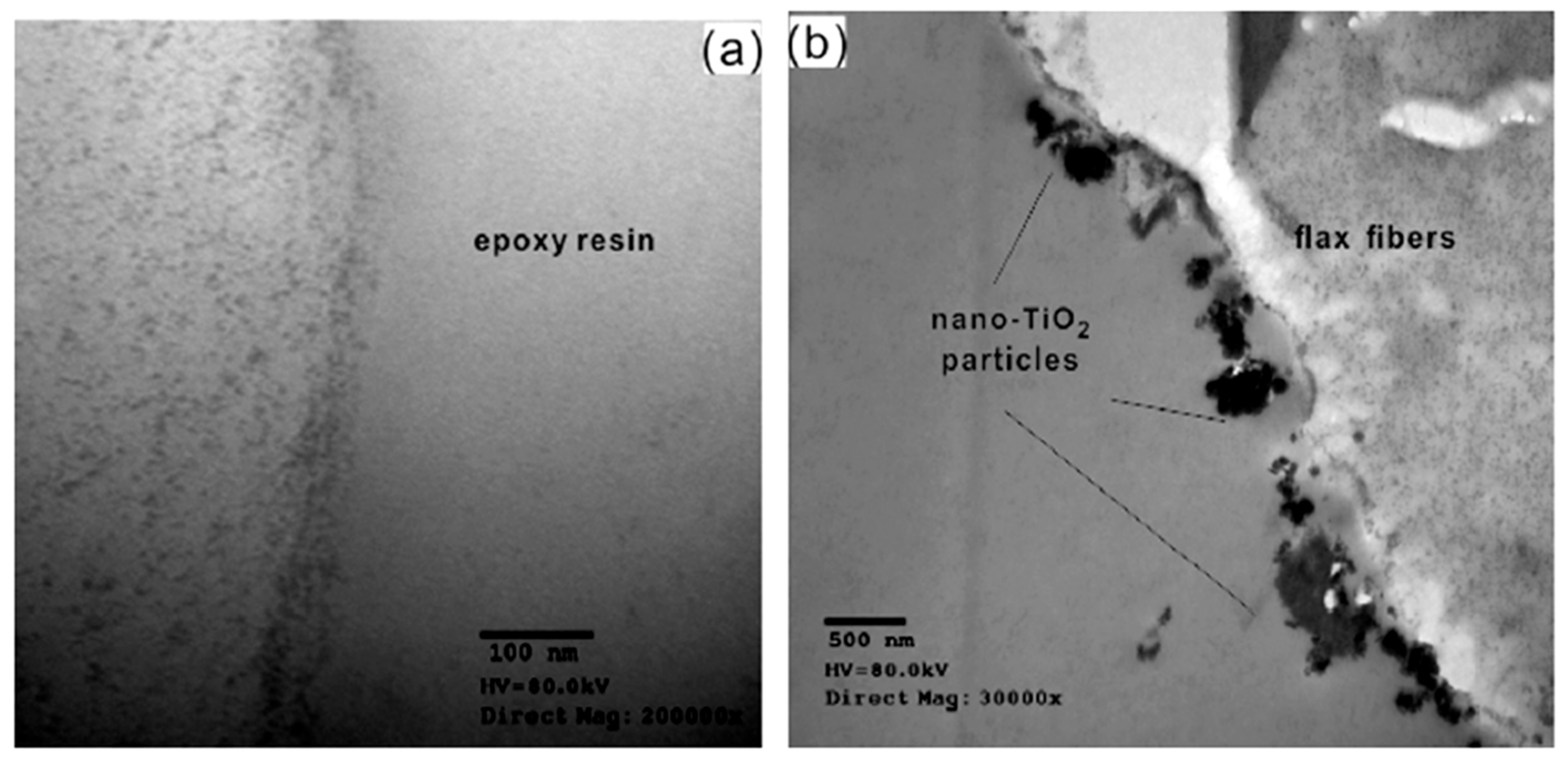
| Epoxy resin/flax fibres | Nano-TiO2 particles, dipping in nano-TiO2/KH560 suspension (optimum results with 2.34 wt% nano-TiO2 and higher tensile strength of single fibre) | Non-uniform distribution of nano-TiO2 with the presence of aggregates (150–300 nm) | – | ▲ 20.7 ± 1.7 MPa → 29.3 ± 1.3 MPa Microbonding technique (single fibre) | Flexural strength and modulus: ▲ 30% and ▲ 17% resp. | Wang et al., 2015 [67] |
| Synthetic Fibres + Biobased Nano-Objects | ||||||
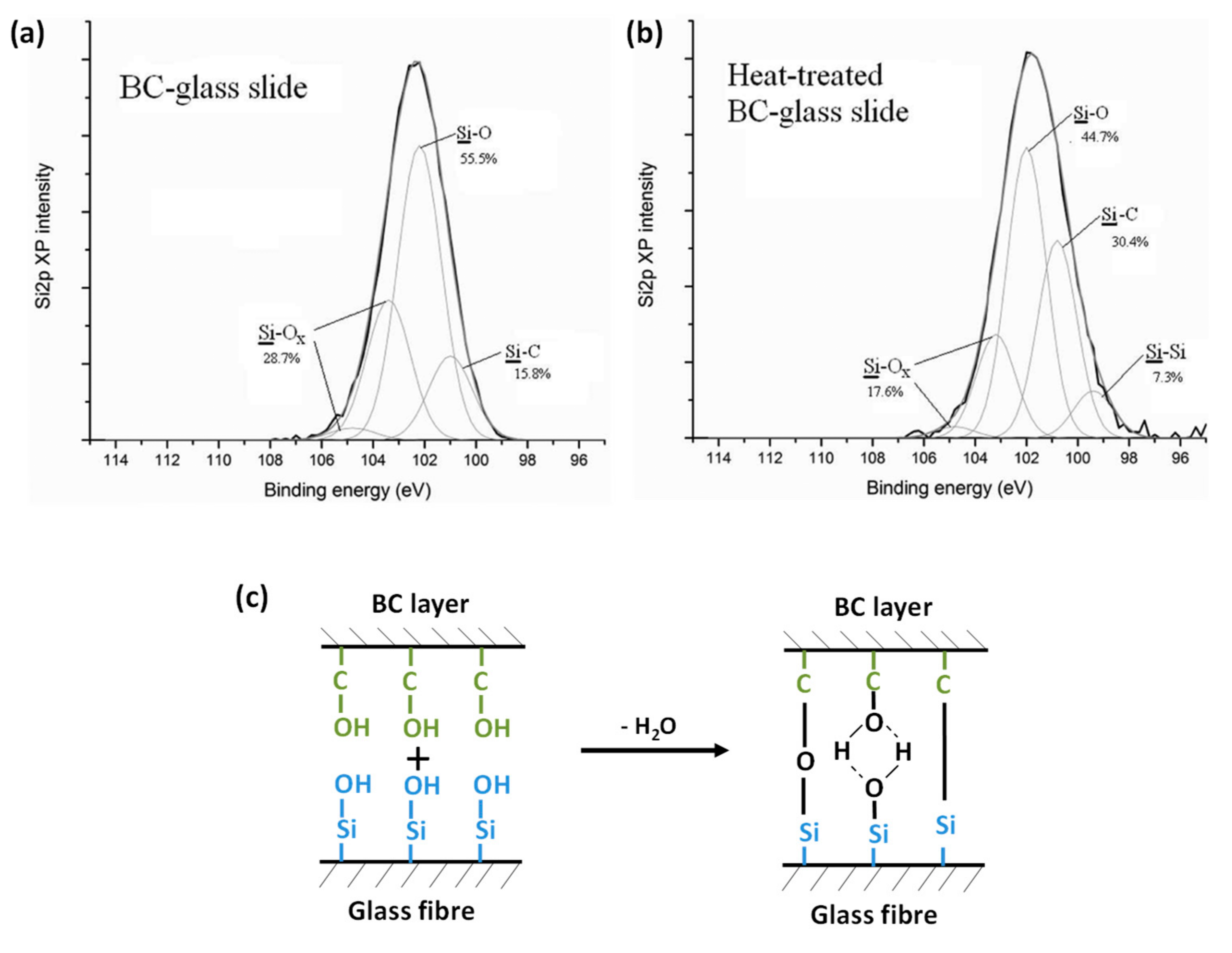
| Epoxy resin/glass fibres | BC, dipping of fibres in BC culture medium, fermentation process | BC-based pellicles around glass fibres | ~30° → 63.5° Sessile drop technique (water/air) on (BC-)glass slides ▼Drawback: no values with epoxy matrix | ▲ 14.1 ± 1.9 MPa → 21.5 ± 2.2 MPa Microbonding technique (single fibre) | – | Chen et al., 2014 [79] |
| Epoxy resin/chopped glass fibre roving | CNC, dipping in aqueous suspension (optimum results for 1 wt% CNC) | Partial penetration of CNC within the roving | – | ▲ 32.2 ± 3.8 MPa → 53.5 ± 4.3 MPa SFFT technique | Tensile properties: no improvement, Flexural strength and modulus: ▲ 39.3% and ▲42.9% resp. | Asadi et al., 2016 [80] |
| Matrix/Fibre | Nano-Objects, Treatment Method | Properties | Ref. | |||
|---|---|---|---|---|---|---|
| Surface Properties | Wettability | Micro-Mechanical Test, IFSS | Composite Microstructure and Properties | |||
| PLA/sisal fibres | BC, growth on fibre surface (3–7 days, 30 °C), fermentation process ▼1 Drawback: long incubation time, decrease of fibre tensile strength and Young’s modulus | BC nanofibers randomly oriented on fibre surface | – | ▲1 IFSS: 12.1 MPa ± 0.5→ 14.6 MPa ± 1.2 Single fibre pull-out technique | Longitudinal tensile strength and modulus: ▲ 44% and ▲ 42% | Juntaro et al., 2007 [84] and Pommet et al., 2008 [28] |
| PLA/hemp fibres | – | Longitudinal tensile strength and modulus: ▼ 5.2% and ▼ 33% | ||||
| CAB/sisal fibres | ▲ IFSS:1.02 MPa ± 0.06→ 1.49 MPa ± 0.03 Single fibre pull-out technique | Longitudinal tensile strength and modulus: ▲ 8.1% and ▲ 59% | ||||
| CAB/hemp fibres | ▲ IFSS: 0.76 MPa ± 0.06→ 1.83 MPa ± 0.12 Single fibre pull-out technique | Longitudinal tensile strength and modulus: ▼ 12% and ▼ 32% | ||||
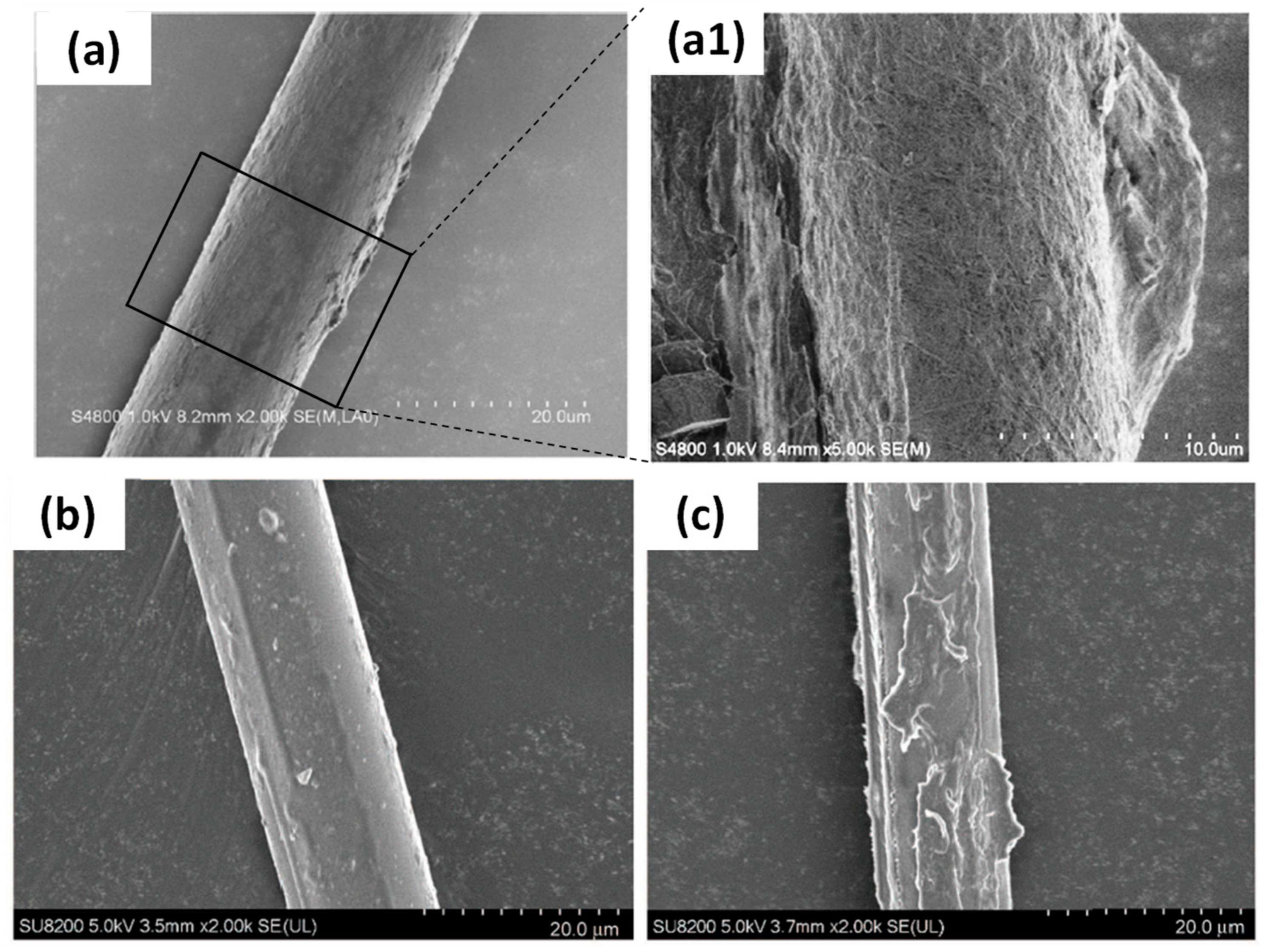
| PLA/sisal fibres | BC, dipping in freeze-dried BC suspension (3 days) ▼ Drawback: long incubation time, decrease of fibre tensile strength and Young’s modulus | Surface area: ▲ 390% and ▲ 670% for “hairy” and “dense” BC-sisal fibres, respectively | – | – | “Dense” BC-sisal fibre: Tensile strength and modulus: ▼ 2.4% and ▲5.5% resp. Flexural strength and modulus: ▼ 6.1% and ▲ 7.0% resp. “Hairy” BC-sisal fibre: Tensile strength and modulus: ▼ 1.5% and ▲ 0.8% resp. Flexural strength and modulus: ▼ 3.4% and ▲ 2.3% resp. | Lee et al., 2012 [86] |
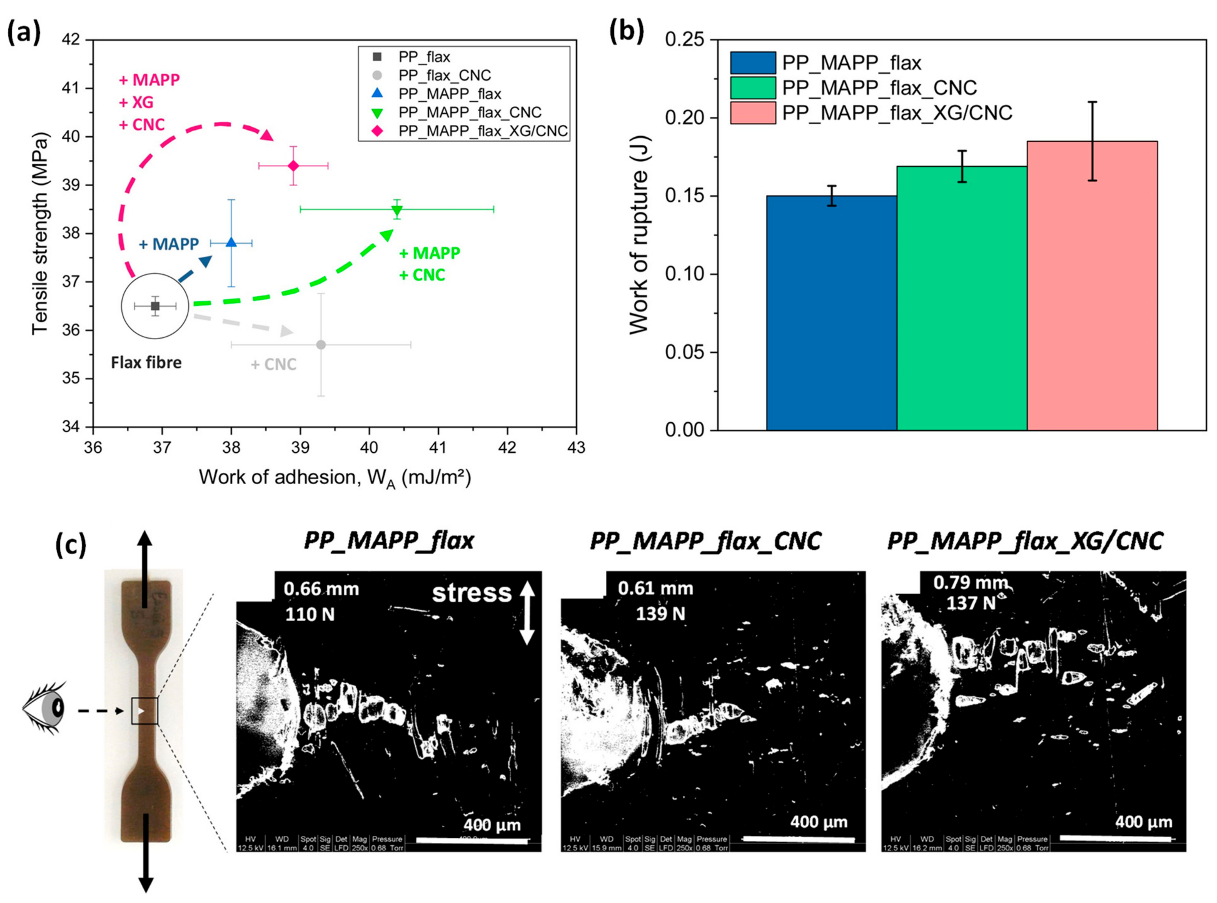
| PP/MAPP/flax fibres | CNC and xyloglucan (XG), dipping in aqueous suspension | Homogeneous adsorption, creation of an extensible network XG/CNC at the surface of the fibre | ▼ fibre polarity by 29%with CNC at the surface, ▲ work of adhesion fibre/PP by combining MAPP with XG/CNC (+ 5.4%) or CNC (+ 9.5%) | ▲ 23.2% of the work of rupture with the treatment XG/CNC compared to PP/MAPP/neat flax fibres, Crack propagation more uneven with numerous micro-cracks (micro-tensile test in situ SEM) | ▲ Tensile strength: 36.5 MPa → 39.4 MPa (MAPP coupling agent and XG/CNC) | Doineau et al., 2020 [91] and Doineau et al., 2021 [94] |
Publisher’s Note: MDPI stays neutral with regard to jurisdictional claims in published maps and institutional affiliations. |
© 2021 by the authors. Licensee MDPI, Basel, Switzerland. This article is an open access article distributed under the terms and conditions of the Creative Commons Attribution (CC BY) license (http://creativecommons.org/licenses/by/4.0/).
Share and Cite
Doineau, E.; Cathala, B.; Benezet, J.-C.; Bras, J.; Le Moigne, N. Development of Bio-Inspired Hierarchical Fibres to Tailor the Fibre/Matrix Interphase in (Bio)composites. Polymers 2021, 13, 804. https://0-doi-org.brum.beds.ac.uk/10.3390/polym13050804
Doineau E, Cathala B, Benezet J-C, Bras J, Le Moigne N. Development of Bio-Inspired Hierarchical Fibres to Tailor the Fibre/Matrix Interphase in (Bio)composites. Polymers. 2021; 13(5):804. https://0-doi-org.brum.beds.ac.uk/10.3390/polym13050804
Chicago/Turabian StyleDoineau, Estelle, Bernard Cathala, Jean-Charles Benezet, Julien Bras, and Nicolas Le Moigne. 2021. "Development of Bio-Inspired Hierarchical Fibres to Tailor the Fibre/Matrix Interphase in (Bio)composites" Polymers 13, no. 5: 804. https://0-doi-org.brum.beds.ac.uk/10.3390/polym13050804