
Effect of Asymmetry of Channels on Flows in Parallel Plates with a Sudden Expansion


Department of Aeronautics and Astronautics, Tokyo Metropolitan University, Hino 191-0065, Japan
*
Author to whom correspondence should be addressed.
Symmetry 2021, 13(10), 1857; https://0-doi-org.brum.beds.ac.uk/10.3390/sym13101857
Submission received: 24 September 2021
/
Revised: 29 September 2021
/
Accepted: 30 September 2021
/
Published: 3 October 2021
(This article belongs to the Special Issue Symmetry in Fluid Flow II)
Abstract
:In order to quantitatively grasp the influence of asymmetry of a channel, flow in an eccentric sudden expansion channel, in which the channel centers are different on the upstream and downstream sides, was calculated to be less than the Reynolds number of 400, where the expansion rate was 2. The asymmetry of a channel is expressed by an eccentricity S, where a symmetric expansion channel is S = 0 and a channel with one side step is S = 1. Both flows firstly reattached on the wall located on the short and long side of a sudden expansion and were observed in the range of S ≤ 0.2, although only the former was seen in the range of S > 0.2. The critical Reynolds number of the multiple solutions increases parabolically to S. At least two separation vortices occur, and the third separation vortex is generated in both solutions above the critical Reynolds number of the third vortex. The length of an entrance region increases linearly to the Reynolds number and slightly with the increase in S. The pressure drop coefficient is proportional to the power of the Reynolds number and increases with S.
1. Introduction
Flows in parallel plates with a sudden expansion is a basic research subject in fluid mechanics, and many reports have been published over the years in terms of both experiments and calculations [1,2,3,4,5,6,7,8,9]. For these flows, it is assumed that the central axes of the flow path coincide with each other on the upstream side and the downstream side, unless otherwise specified. A flow in a channel with a sudden expansion is regarded as being two-dimensional in the low Reynolds number region. Therefore, the symmetrical flow becomes linearly unstable against the disturbance at the Reynolds number or higher. Instead, the asymmetrical flow becomes stable. At that time, the solution of the asymmetric flow is branched from that of the symmetric flow by pitchfork bifurcation. When the Reynolds number becomes higher, the third detachment vortex is generated, and it transits to the transient flow on the order of 10-squared [2,3,4]. In addition, attempts have been made to clarify heat transfer property [5], and recently research with three-dimensional calculation [6,7] and by the LES [8] has been attempted. For the case where the step is only on one side, the details are being investigated as well [9].
The effect of asymmetry of a flow channel has not been fully investigated. As one of the asymmetrical flow channels, there is a flow in a flow channel with a deviation in the central axis before and after the sudden expansion. Where the deviation of a central axis against the flow channel height is called eccentricity, it has already been investigated for the case with small eccentricity by experiment and theoretical analysis. The flow in such flow channel definitely becomes asymmetric [10]. Below the critical Reynolds number, there is only one stable solution, while at the critical Reynolds number or higher, there are two stable solutions and one unstable solution. Although the branch structures of these solutions are imperfect, these are the structures where the perfect pitchfork bifurcation generated by the flow in a symmetrical sudden expansion channel was collapsed [11]. Kato has investigated the flows in an apparently asymmetric sudden expansion channel, and they showed the qualitative tendency of the flow pattern against the changes in the Reynolds number and the eccentricity [12].
However, quantitative properties such as the critical Reynolds number or reattachment point length have not yet been clarified. Besides that, as an asymmetric flow geometry, the case where the position of the sudden expansion is shifted up and down, can be considered. When the normalization is performed by the critical Reynolds number and the detachment vortex length at that time, it can be compared with the flow in the symmetrical flow channel [13,14]. Considering a flow in a suddenly expanded circular tube, there have been numerous reports on the coaxial pipeline [15,16]. However, for non-coaxial shapes, the conditions for the shape and flow-rate have been limited [17].
The existing flow channels have more or less asymmetry. Even if the center of the flow channel is specified to be coaxial in the drawing, the geometrical tolerance must always be set. A case can be supposed where the flow channel inevitably becomes asymmetrical due to the circumstances of the mechanical strength and the surrounding instruments. For example, to fabricate micro/nanoscale hierarchical structures on one side of polytetrafluoroethylene mesh surfaces, the asymmetrical mesh shows excellent stability during corrosion and abrasion tests [18,19]. However, since there are many unknown factors in their various properties, we refrain from adopting them.
Under such circumstances, in order to provide basic knowledge on an asymmetrical flow channel, we have investigated the flow in parallel plates where the central axis of the flow channel is different between before and after the sudden expansion part. One of the authors has previously reported the case where the expansion ratio of the flow channel height is 3 [20]. In the present study, by limiting the expansion ratio of the flow channel height to 2, the speed distribution and pressure distribution in a flow field were clarified by the two-dimensional calculation in the range of the Reynolds number of 400 or less. In the calculation, the extent of the effects of the results on the inner flow were evaluated by variously changing the ratio of the eccentricity with respect to the flow channel height.
2. Methods
2.1. Configuration of Problem
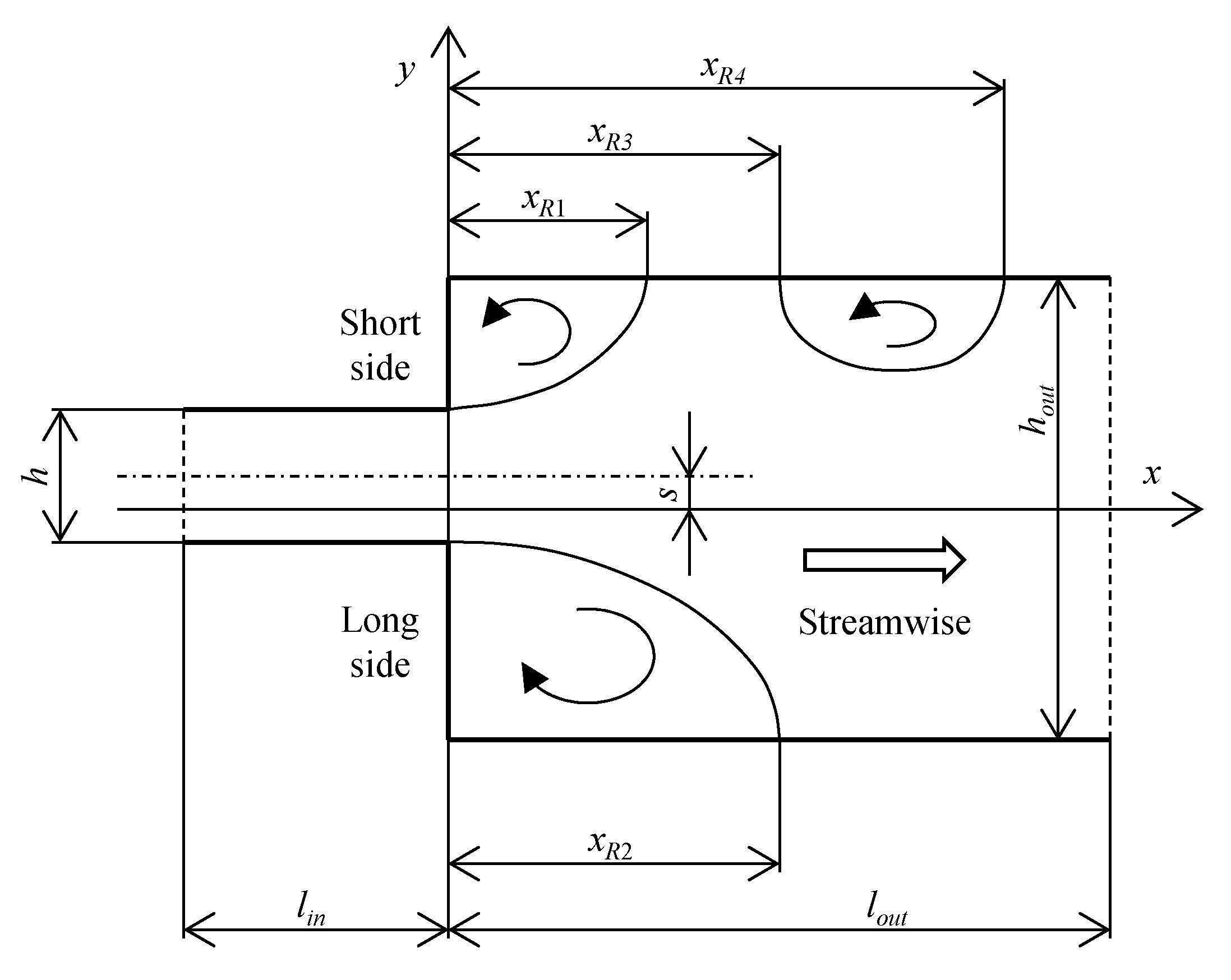
Figure 1 shows the calculation area and two-dimensional coordinate system. The origin was set to be the intersection between the vertical wall surface of the sudden expansion region and the center line of the flow channel on the downstream side. The x and y axes were set to be the mainstream direction and the vertical direction, respectively. As to the shape, two dimensionless parameters, expansion rate E and eccentricity S, were defined by the following Equations (1) and (2), respectively,
where h [m] is the flow channel height on the upstream side, hout [m] is that on the downstream side, and s [m] is the distance between the central axes of the upstream side and the downstream side. For the vertically symmetrical flow channel, S = 0, and in the case where the step exists only on one side, S = 1. In the present paper, only the case of E = 2 was treated.
First, the two-dimensional incompressible viscous laminar flow was verified in this region. For time t [s], space x = (x, y) [m], pressure p [Pa], and velocity u = (u, v) [m/s], the governing equations are the continuity Equation (3) and the Navier–Stokes Equation (4),
where the constants are the density ρ [kg/m3] and the dynamic viscosity coefficient ν [m2/s].
Further, the variables in the above equations were made dimensionless by letting the average flow velocity on the upstream side be the representative flow velocity u0 [m/s].
At that time, the Reynolds number is defined as Re = u0h/ν.
The calculation area was adjusted so that the length of the rear flow channel sufficiently exceeds the entrance distance. The lengths of the front and rear flow channels were set to be Lin = lin/h = 10 and Lout = lout/h = 100, respectively. Although the initial values for both the pressure and the velocity were basically set to be 0, another calculation result was used as the initial value if necessary. For the boundary condition at the inlet, the velocity distribution expressed by the plane Poiseuille flow was given as shown below.
At the outlet, the Sommerfeld radiation condition was applied to the velocity. For the pressure, the boundary condition was set so that the average value became 0.
Here, Uc is the advection velocity in the X direction. For the value of Uc, the average flow velocity was adopted. The wall surface was assumed to be no slip (U = V = 0).
2.2. Numerical Method
The governing Equations (3) and (4) were discretized by the finite volume method. Many numerical simulations using this method have been reported so far [20,21,22,23,24,25]. The present authors have studied the flow in sudden expansion/contraction channels and the flow in sudden contraction channels using this method [23]. In these studies, a calculation region was divided by an equally spaced mesh, and the space notch was set to be ΔX = ΔY = 0.05. These conditions had the same accuracy as those of the numerical analysis by Nakanishi et al. [3]. The time increments were set to be ΔT = 0.001.
The algorithm for the calculation was as follows. The discrete expressions were repeatedly solved based on the Pressure-Implicit with Splitting of Operators method. In this method, multiple correction steps are performed for a pressure correction equation. In the present study, a pressure correction equation was solved two times. As to the time term, the first-order backward Euler method was applied. For the other terms, the second-order central difference method was used in combination with the second-order Gaussian integration method. As to the iterative solution, the geometric-algebraic multi-grid method was applied to the pressure, while the Gauss–Seidel method was adopted to the velocity. For the judgement of the calculation end, the convergence was judged to end at the time when the L1 norm became 10−10 or less.
For the flow channel at E = 2, two-dimensional numerical simulation was performed in the range of 20 ≤ Re ≤ 400 [3] and 100 ≤ Re ≤ 600 [5]. Moreover, in order to secure that the flow is a steady flow in the region of Re ≤ 400, the calculation was performed also at Re = 500, by extending the length of the downstream flow channel. Based on these calculation results, it was confirmed that the flow was the steady flow. From these results, the calculation region in the present study was set to be 20 ≤ Re ≤ 400.
3. Results and Discussion
As shown in Figure 1, for the flow in the channel where the cross-section of the flow channel is suddenly changed, the flow separation occurs downstream of the sudden expansion region; thereby, vortices are generated by the backflow. Then, the flow reattaches to the wall in some downstream region. This process is a phenomenon that is called a peeling vortex. The flow in a sudden expansion channel is characterized by this peeling vortex. The shape of the vortex is expressed by the distance from the sudden expansion part to the reattaching points R1, R2, R4, and the peeling point R3 [3].
In the present study, three kinds of critical Reynolds numbers have been investigated. First, in the case of S = 0, the transition from the symmetric flow to the asymmetric flow was generated. Letting the critical Reynolds number be Resym, the results were compared with those in the previous study [3]. In the condition S ≠ 0, when the Reynolds number became a certain value or higher, the multiple solutions composed of two stable solutions were obtained. The critical Reynolds number in this condition was expressed as Remul. Note that it was clarified that both Resym and Remul are the branch points of the pitchfork bifurcation in terms of classification of solution branches [26]. Furthermore, the critical Reynolds number where the number of the peeling vortices becomes 2 or 3 was expressed as Re3rd. In the present paper, the peeling vortex characterized by the peeling point R3 and the reattachment point R4 was called the third peeling vortex.
3.1. Comparison with Previous Papers
Before calculating the flow in an eccentric channel, the reproducibility of the calculation was verified by comparing the calculation results for a symmetric flow channel at E = 2 and S = 0 with previous studies. For example, Ota et al. have reported that the flow transits from symmetric flow to asymmetric flow in the range of 100 < Resym < 200, and generation of the third peeling vortex region was observed at Re3rd ≥ 300 [5]. Nakanishi et al. also have reported the result of Resym ≈ 100 and Re3rd ≈ 300 as the calculated values [3]. In the present study, the values of Resym = 147.6 and Re3rd = 274.5 were obtained. The method to determine the critical Reynolds number is described in Section 3.4.
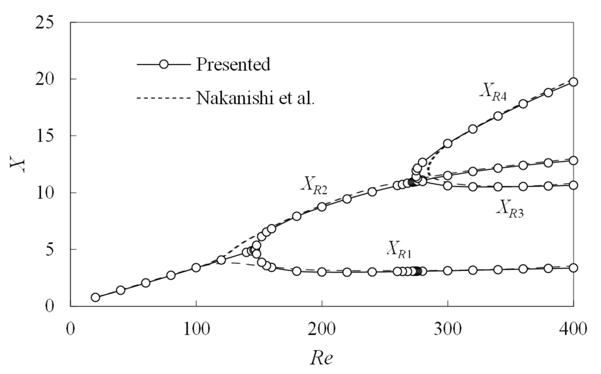
For the branch structure of the reattachment length, the present results were compared with the branch diagram based on the calculation by Nakanishi et al. [3], which is shown in Figure 2. It is seen that both results well coincide, except for the region near the branch point. From these results, it was judged that the results of the present study have enough accuracy. In order to determine the points of reattachment/peeling, dimensionless wall shear stress τX = Re−1(∂U/∂Y) was calculated, and the point at τX = 0 was set to be the reattachment/peeling point. The branch structure where a symmetric flow transits to the asymmetric flow is the perfect pitchfork bifurcation [10], so the branching solutions for the asymmetric flows XR1 and XR2 connect smoothly in a U-shape. This fact can be deduced from the present calculation results. It has been reported that it is difficult to identify the critical Reynolds number of the flow in the sudden expansion channel, as the results of the critical Reynolds numbers tend to vary depending on the researcher [27].
At E = 3, the precise critical Reynolds numbers that transit from a symmetric flow to the asymmetric flow have been reported. For example, Fearn et al. have reported that they observed the transition from a symmetric flow to the asymmetric flow at Resym = 53.9 by the numerical simulation [10]. In addition, for the weakly nonlinear stability analysis, the value of Resym = 53.7 was reported [26]. In addition, when the calculation was performed by a method that is equivalent to the present one, it was found that the flow became asymmetric at Resym = 54.9 [20].
3.2. Flow Pattern
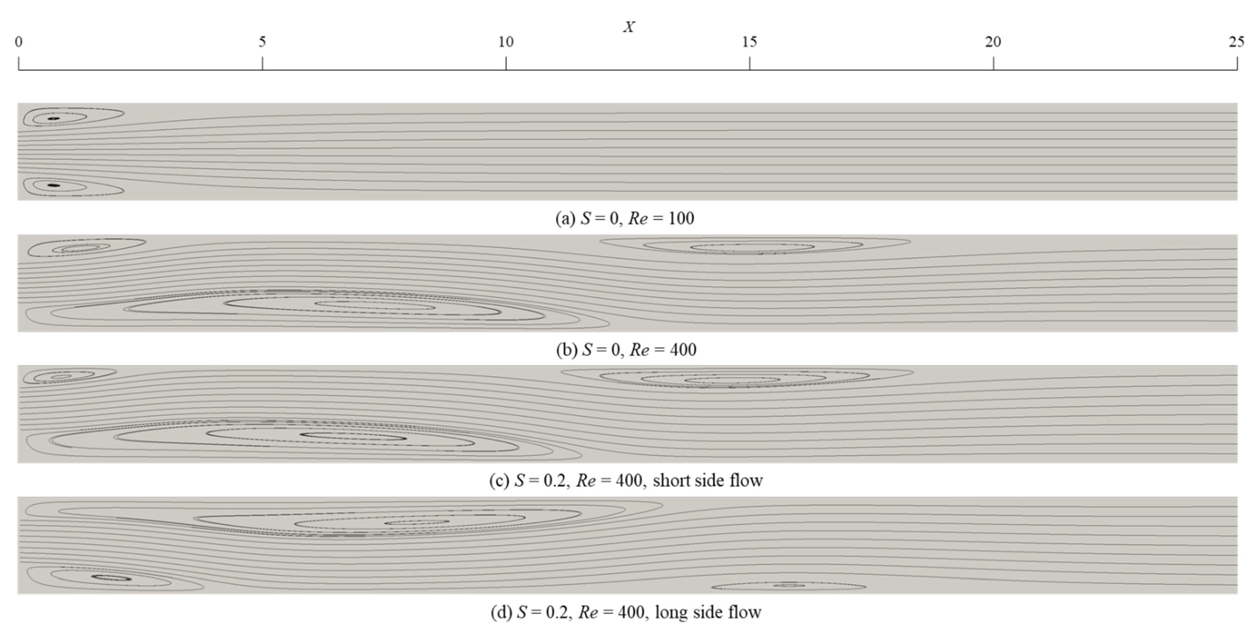
Figure 3 shows the pattern for the streamline. For the symmetric flow channel of S = 0, the symmetric flow was obtained (a) when the Reynolds number was small. At that time, two peeling vortices of the same size were generated. If the Reynolds number exceeded Resym, the asymmetric flow appeared. At this stage, the number of vortices was still two, but the size was different. Further, when the Reynolds number exceeded Re3rd, the third peeling vortex was generated, so the number of total vortices became 3 (b). In the region of the asymmetric flow channel of 0 < S < 1, the main flow first reattached to the shorter part of the sudden expansion wall surface (c). This flow is called a short-side flow. Similar to the symmetric flow channel, two or three peeling vortices were generated. For S = 1 where the steps were on only one side, the vortices were not generated on the short side just after the sudden expansion, so the number of the vortices was one or two. In addition, when the Reynolds number exceeded Remul, the solution where the main flow reattached to the long side of the sudden expansion wall surface also held (d). This is called long-side flow.
3.3. Reattachment Length
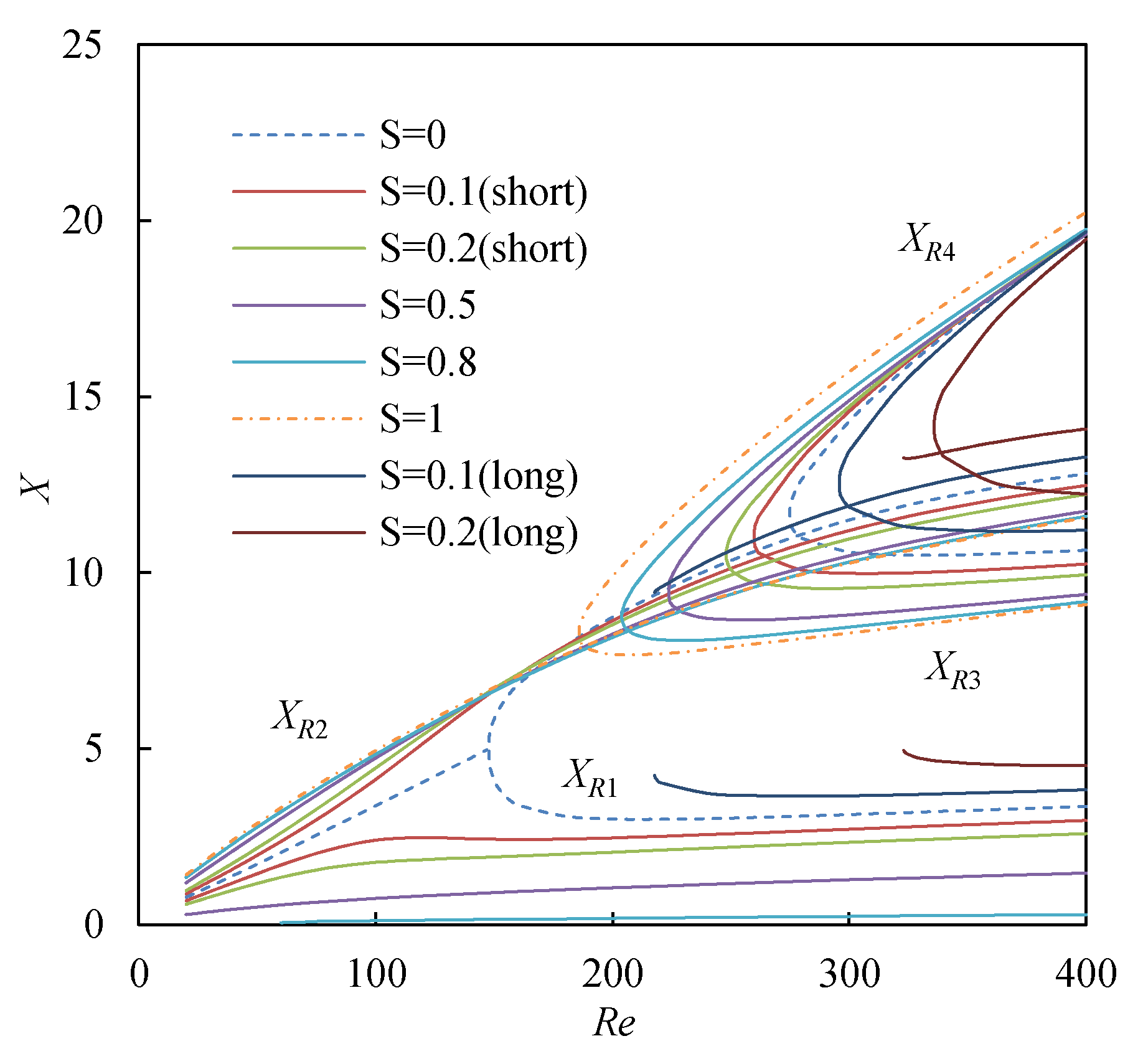
As has been used for comparison with the previous studies described in the above Section 3.1, the characteristics of the flow in the eccentric channel were verified by obtaining the distance XR1–XR4 between the reattachment and peeling points. Figure 4 shows the diagram of XR1–XR4 at six eccentricities of S = 0, 0.1, 0.2, 0.5, 0.8, and 1.
First, a short-side flow will be described. The first reattachment point distance XR1 did not agree with the second reattachment point distance XR2, and the difference in the distance increased with the increase in the Reynolds number. For XR1, the larger the eccentricity was, the smaller the value gradually became. On the other hand, the value of XR2 did not change much with the eccentricity. It should be noted that all of the branching solutions for XR2 except for S = 0 crossed in the extremely narrow region, which can be regarded as one point around Resym. Therefore, in the condition of Re < Resym, the larger the value of S is, the larger the value of XR2 becomes. However, this tendency became reverse in the condition of Re > Resym. As to the peeling point XR3 and the third reattachment point XR4, the difference depending on the eccentricity became smaller with the increase in the distance from the two nodes. The critical Reynolds number Re3rd where the third peeling vortex was generated decreased with the increase in the eccentricity.
Next, a long-side flow will be described. In the condition of Re ≤ 400, the long-side flow was confirmed at S = 0.1 and 0.2. The values of both XR1 and XR2 became longer than those in the short-side flow. From the comparison between XR3 and XR4, it was clarified that the size of the third peeling vortex in the long-side flow became smaller than that in the short-side flow. However, since the values of XR4 in the long-side flow were almost the same as those in the short-side flow, the region that influenced the downstream was not so different even if one of the two multiple solutions appeared. The critical Reynolds number Re3rd where the third peeling vortex was generated increased with the eccentricity, which was reverse to the case of the short-side flow.
For E = 2, both the presence and absence of the peeling vortex were confirmed in the long-side flows at both S = 0.1 and S = 0.2. That is, both flows had a relation, Remul < Re3rd. However, this relation depended on the value of S, so the relation was sometimes reverse at E = 3, i.e., Remul > Re3rd [20].
Furthermore, it was found that warp of the branching solution of the long-side flow tended to become tight while getting lower to Remul. From the numerical analysis in the previous study, it has been elucidated that an unstable solution exists in the flow in the asymmetric sudden expansion channel, and the solution merges while being in contact with that of the long-side flow at the critical Reynolds number [10]. The warp around the critical Reynolds number obtained in the present study is considered to reflect the characteristics of the branch structure.
3.4. Critical Reynolds Number
Table 1 shows the values of Resym, Remul and Re3rd with respect to S. Although calculations were converged under all conditions, it took a long time to converge at around Resym and Remul. In calculating Remul, the existence range was narrowed down by gradually making the Reynolds number smaller by setting the long-side flow to be the initial value. Finally, the interval of the Reynolds number was made smaller down to 0.1, and the smallest Reynolds number where the long-side flow was obtained was set to be Remul. Therefore, the true critical Reynolds number Rec is expected to be in the range Remul − 0.1 < Rec ≤ Remul. Further, the existence of Remul was confirmed at S = 0.1 and 0.2 in the condition of Re ≤ 400, but the existence was not confirmed at S = 0.3. As to Re3rd, the critical value was identified by conducting the spline interpolation for the distribution of XR3 and XR4 with respect to Re.
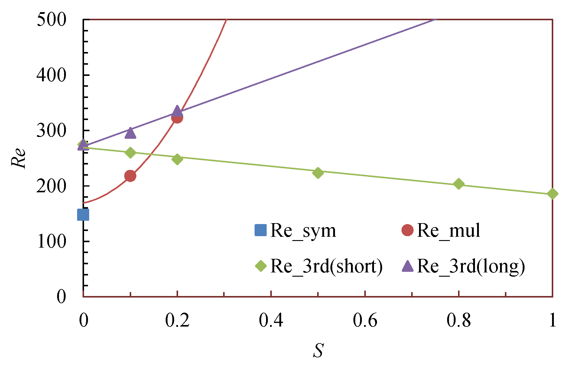
Figure 5 shows the distribution of these critical Reynolds numbers. In the previous study on E = 3, it was found that the approximate curve for Remul is parabolic [20]. As one of the important properties, the fact that Resym estimated from this approximate curve is larger than the actually obtained Resym can be mentioned. In the numerical simulation by Mizushima and Shiotani, they discussed the flow in a flow channel that has extremely small asymmetry at E = 3 and S = 0.00125, and they obtained the value Remul ≈ 59 [26]. Compared with the value Resym = 53.64 at S = 0 obtained with the similar method, the critical value increased by about 10%, so it can be said that the change was dramatic. In the present calculation, although the long-side flow was obtained from only two eccentricities, the approximate curve at E = 2 was estimated based on the abovementioned characteristics.
In the present study, although the calculation was conducted for the long-side flow only at two eccentricities, the approximate curve at E = 2 was estimated based on the abovementioned characteristics. Further, it was found that Re3rd in the short-side flow decreased linearly with the increase in S, while Re3rd in the long-side flow showed the tendency to increase. Figure 5 shows the approximate line drawn assuming that Re3rd in the long-side flow is linear with respect to S.
3.5. Entrance Length
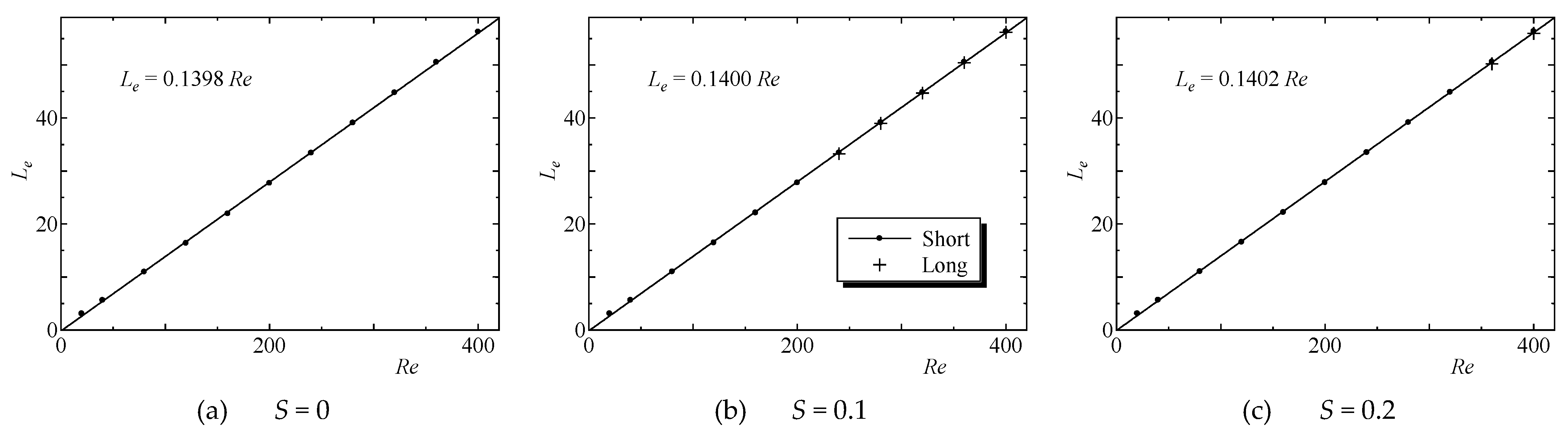
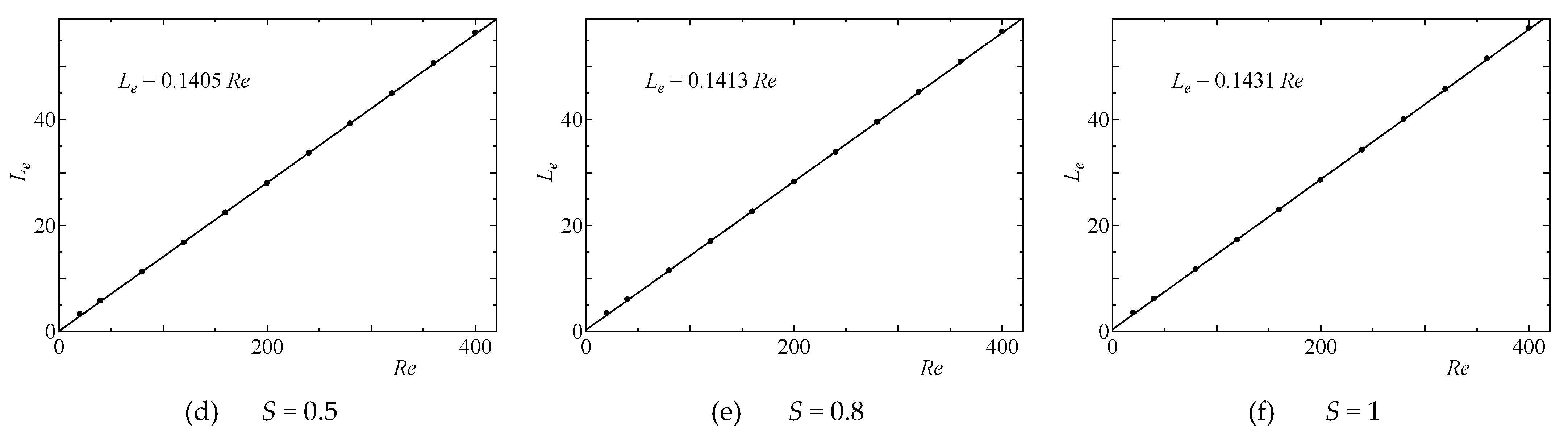
To define the entrance length, that is the length of the entrance zone, the position where the flow is sufficiently developed was identified. Specifically, at the center of the flow Y = 0 on the downstream side of the sudden expansion part, the endpoint of the entrance zone was defined as the position where the error of the flow velocity U in the main flow direction with respect to the plane Poiseuille flow (U = 0.75) became ±1%. Further, the dimensionless distance from the plane at the sudden expansion part to this endpoint was defined as the entrance length Le.
Figure 6 shows the plot for the values of Le, obtained by the abovementioned procedure. For all values of S, Le increased linearly with the increase in Re. The approximate equation is indicated in Figure 6. This equation well agreed with the obtained values at Re ≥ 20. However, when the Reynolds number is extremely small, such as Re ≈ 1, it was reported that the deviation from the linear approximate equation became larger [20].
Furthermore, it was found that the value of Le tended to increase with the increase in S. The difference in Le depending on S was more clearly observed at low Reynolds number. However, the difference gradually decreased with the increase in Re, and the difference between S = 0 and S = 1 at Re = 400 was only less than 2%. For S = 0.1 and 0.2, the value of Le in the long-side flow was smaller than Le in the short-side flow, but the difference was smaller than 1%.
3.6. Pressure Drop
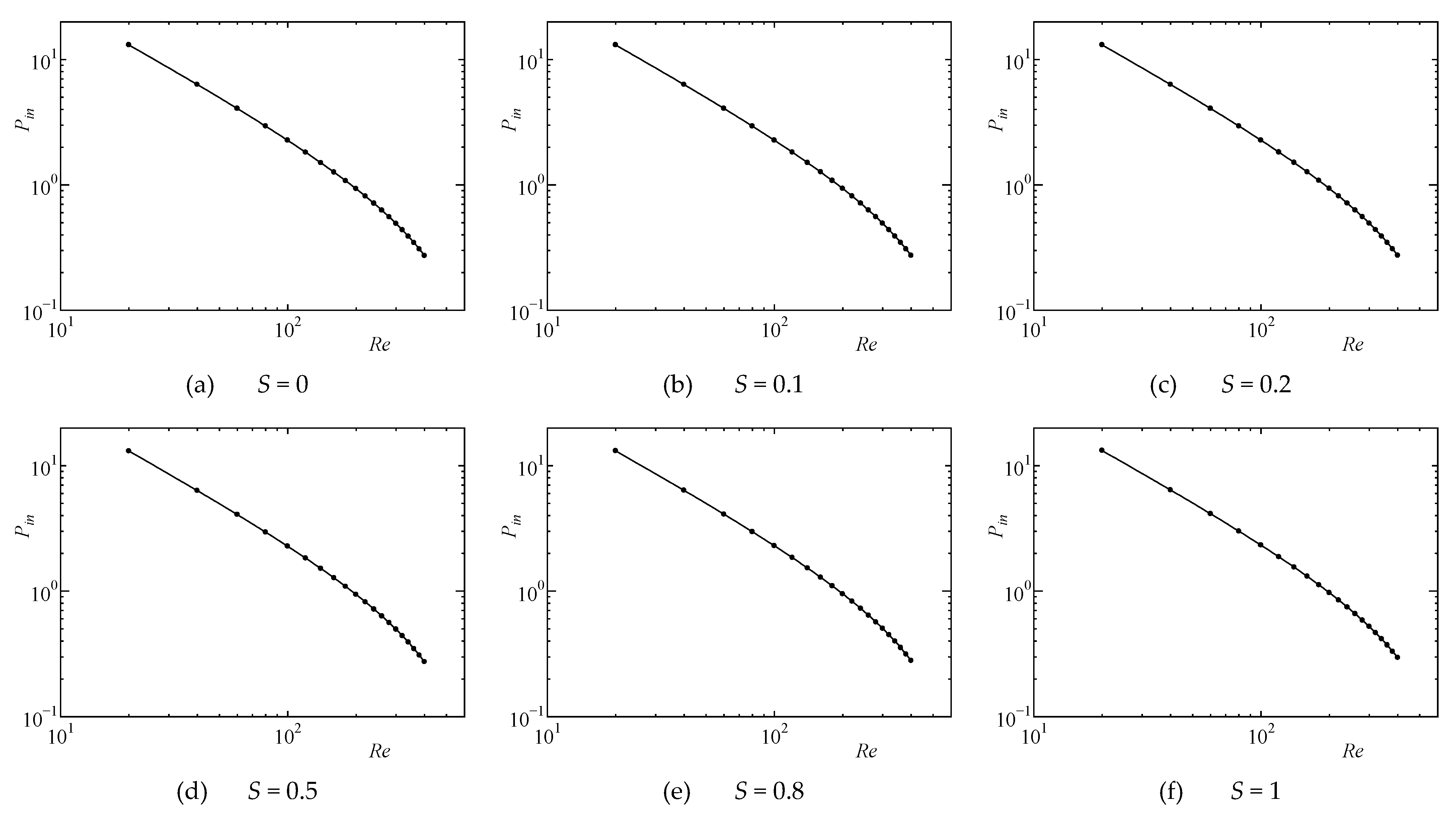
Figure 7 shows the distribution of average pressure Pin at the inlet of flow channel with respect to Re. Regardless of S, the value of Pin was almost proportional to the exponentiation of Re. However, in the range of Re < 100, the value of Pin changed almost linearly on the log–log graph, while it was deviated from the straight line at Re > 100.
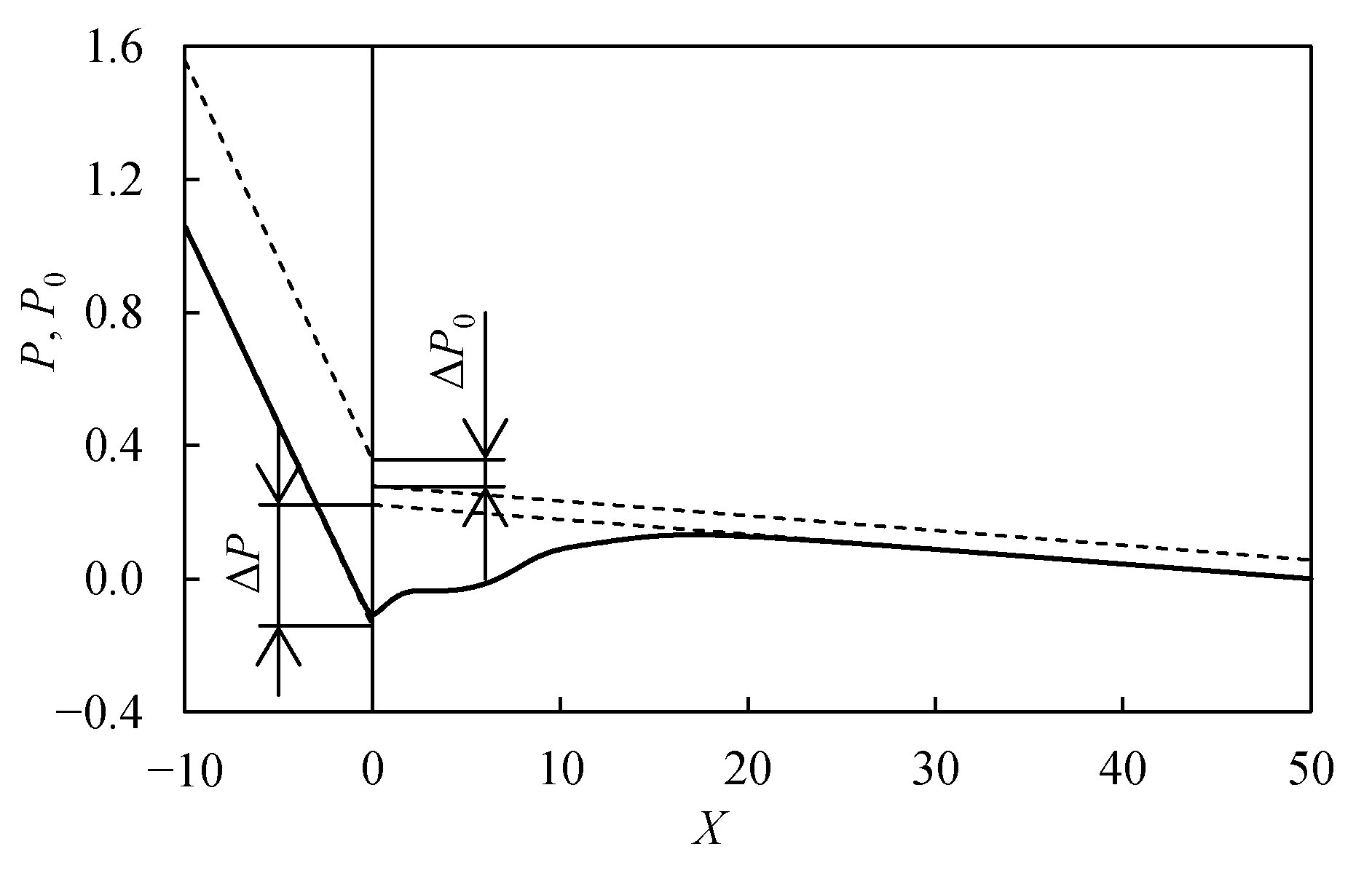
Furthermore, similar to the flow in the sudden expansion circular tube, the pressure loss coefficient ζe originating from the sudden expansion was obtained from the pressure difference between both ends of the flow channel [15]. The definition formula was derived by the following procedure. First, the pressure loss of the flow in the sudden expansion channel is considered by dividing into the loss due to wall friction and the loss due to sudden expansion. The outline of this way of thinking is shown in Figure 8. The solid line in the figure represents the real pressure distribution, and the dotted line indicates the distribution of the static pressure P and the total pressure P0 supposing the wall friction loss. The slope of the thin line dP/dX was obtained from the theoretical equation for the pressure gradient of the plane Poiseuille flow, which is given by the following equation taking Re as a parameter:
The pressure loss by the wall friction was obtained from the static pressures Pin and Pout at the both ends of the flow channel. Then, the difference in the static pressure ΔP at the sudden expansion plane was defined by the following equation:
In most cases, the results were obtained to be ΔP < 0. The total pressure loss ΔP0 due to the sudden expansion is composed of the sum of the difference in the static pressure at the sudden expansion plane and the difference in the dynamic pressure between before and after the flow channel. That is, ΔP0 is given by the following equation:
where Uin and Uout represent the average flow velocity in the sections of −Lin ≤ X ≤ 0 and 0 ≤ X ≤ Lout, respectively. Therefore, the loss coefficient ζe is defined by the following equation:
Since the dynamic pressure corresponding to the denominator in the above equation is constant, the value of ζe is proportional to ΔP0.
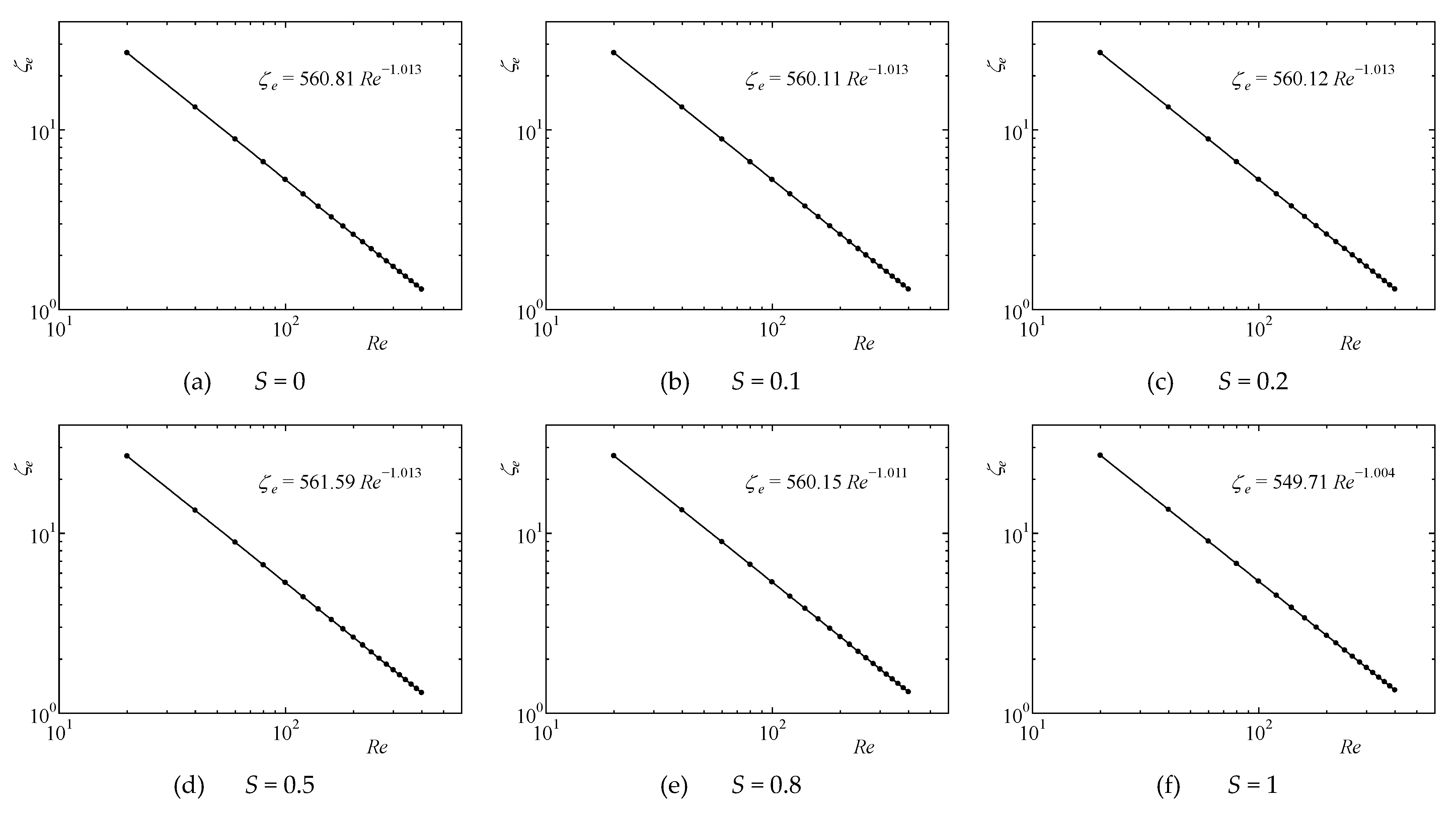
Figure 9 shows the distribution of the pressure loss coefficient ζe for short-side flow with respect to Re. This distribution was linear on the log–log graph, that is, ζe was proportional to the exponentiation of Re. The approximate formula for ζe is also shown in Figure 9.
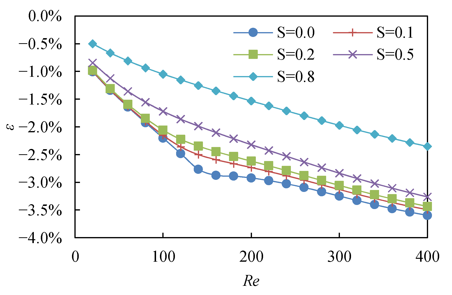
In order to verify the change in ζe against S, the error ε of ζe with respect to ζe at S = 1 was defined for arbitral S. As shown in Figure 10, the value of ε was always negative, and it was the minimum at S = 0. That is, it can be said that the increase in the asymmetry of the flow channel increases the pressure loss. The value of ε at S = 0.1–0.8 was monotonically changed with respect to the increase in Re. On the other hand, the tendency of the change in ε at S = 0 was different with Resym as the boundary. That is, the value of ε changed almost linearly in the range of Re < Resym, but its decreasing rate dropped at Resym or higher, and the value of ε at S = 0 approached that at S = 0.1. From these results, it was elucidated that the pressure loss of the asymmetric flow at S = 0 was larger than that of the symmetric flow.
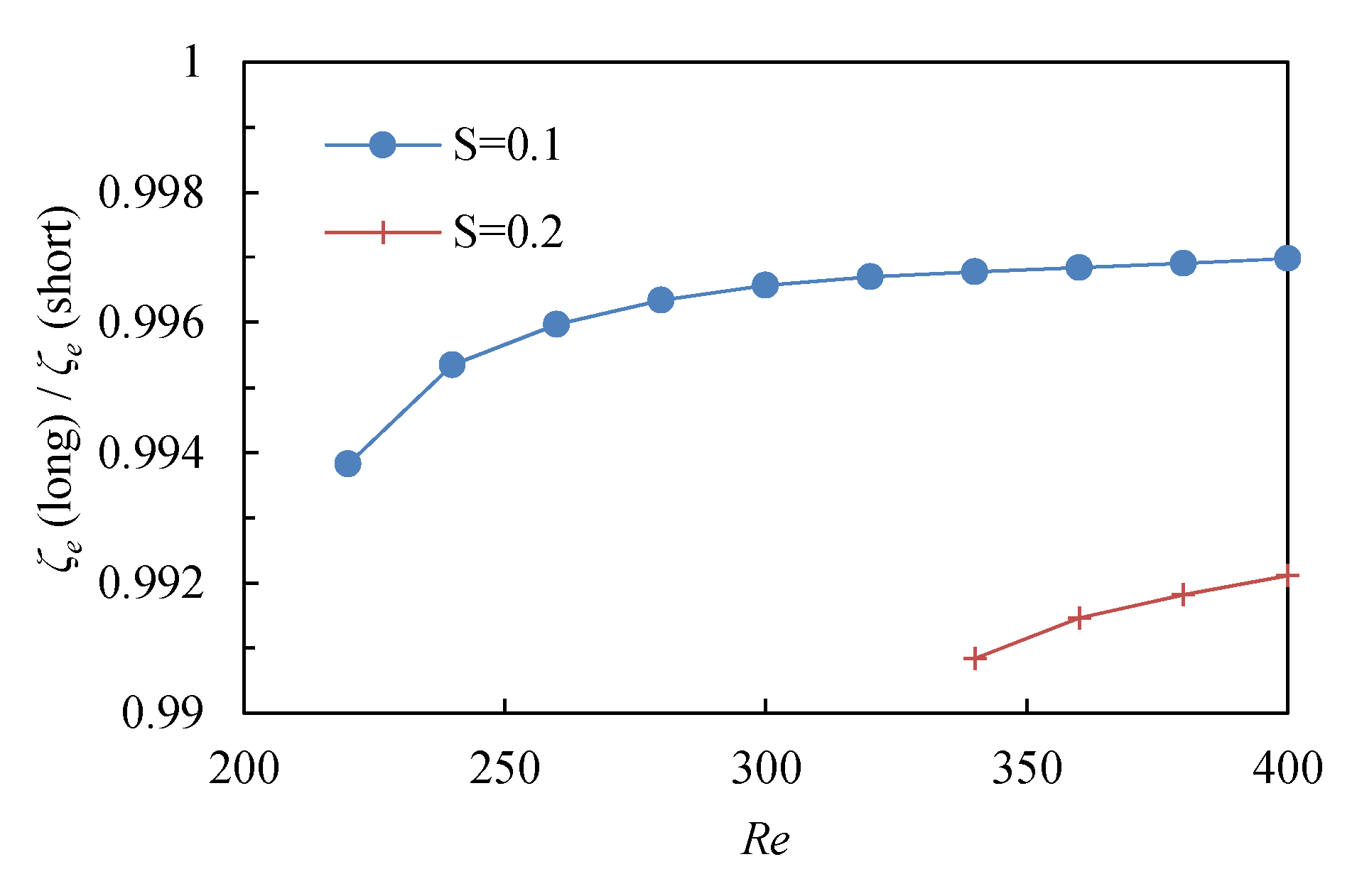
Figure 11 shows the ratio of ζe in the long-side flow to ζe in the short-side flow. It was observed that the values of ζe in the long-side flow were smaller than those of ζe in the short-side flow at all Re. In addition, the difference in the ζe values increased with the increase in the eccentricity.
4. Conclusions
The numerical calculation has been conducted in the range of 20 ≤ Re ≤ 400 for a flow where the center of the flow channel is different between the upstream and downstream sides, that is, a flow in the eccentric two-dimensional asymmetric sudden expansion channel. From the calculation results, the effect of the eccentricity S on the flow properties at the expansion ratio of E = 2 has been clarified. The obtained conclusions when the eccentricity was changed in the range of 0 ≤ S ≤ 1 are shown as follows:
- For asymmetric flow channel, the jet flow first reattached to the short side of the sudden expansion wall surface. When the Reynolds number exceeded the critical Reynolds number Remul, the other solution where the jet flow first reattached to the long side of the sudden expansion wall surface also held. The former process is called short-side flow, and the latter one is called long-side flow. These multiple solutions appeared in the region of S ≤ 0.2. The value of Remul changed parabolically with respect to S.
- At E = 2, the third peeling vortex was generated at the critical Reynolds number Re3rd or higher not only in the short-side flow but also in the long-side flow. The value of Re3rd for the short-side flow decreased linearly with the increase in S, while the value of Re3rd for the long-side flow rather increased.
- The entrance length Le increased linearly with the increase in Re. Although Le became longer with the increase in S, the difference due to the difference in S decreased with the increase in Re. Furthermore, Le for the long-side flow was shorter than that for the short-side flow, but the difference in both values was smaller than 1%.
- The contribution of the sudden expansion part to the pressure loss could be evaluated by the pressure loss coefficient ζe. The value of ζe was proportional to the exponentiation of Re, and it increased as S approached from 0 to 1. Further, the value of ζe for the long-side flow was smaller than that for the short-side flow.
Author Contributions
Conceptualization, T.M.; methodology, T.M.; software, T.M.; validation, T.M. and T.T.; formal analysis, T.M.; investigation, T.M.; resources, T.M.; data curation, T.M.; writing—original draft preparation, T.M.; writing—review and editing, T.M. and T.T.; visualization, T.M.; supervision, T.T.; project administration, T.T.; funding acquisition, T.T. All authors have read and agreed to the published version of the manuscript.
Funding
This research received no external funding.
Institutional Review Board Statement
Not applicable.
Informed Consent Statement
Not applicable.
Data Availability Statement
Data are contained within the article.
Conflicts of Interest
The authors declare no conflict of interest.
References
- Abbott, D.E.; Kline, S.J. Experimental investigation of subsonic turbulent flow over single and double backward facing steps. J. Basic Eng. 1962, 84, 317–325. [Google Scholar] [CrossRef]
- Durst, F.; Melling, A.; Whitelaw, J.H. Low Reynolds number flow over a plane symmetric sudden expansion. J. Fluid Mech. 1974, 64, 111–128. [Google Scholar] [CrossRef]
- Nakanishi, S.; Sakurai, M.; Osaka, H. Numerical study on two-dimensional symmetric sudden expansion channel flow. dynamic characteristics. Trans. Jpn. Soc. Mech. Eng. Ser. B 1995, 61, 3182–3189. [Google Scholar] [CrossRef] [Green Version]
- Hawa, T.; Rusak, Z. The dynamics of a laminar flow in a symmetric channel with a sudden expansion. J. Fluid Mech. 2001, 436, 283–320. [Google Scholar] [CrossRef]
- Ota, T.; Yanaoka, H.; Hata, T. Numerical analysis of laminar flow and heat transfer in a two-dimensional symmetrically enlarged channel. Trans. Jpn. Soc. Mech. Eng. Ser. B 1994, 60, 3930–3936. [Google Scholar] [CrossRef] [Green Version]
- Ota, T.; Yanaoka, H.; Shibuya, K.; Nakajima, M.; Yoshikawa, H. Numerical analysis of separated flow and heat transfer in an enlarged channel. Trans. Jpn. Soc. Mech. Eng. Ser. B 2000, 66, 2109–2116. [Google Scholar] [CrossRef] [Green Version]
- Mishra, S.; Jayaraman, K. Asymmetric flows in planar symmetric channels with large expansion ratio. Int. J. Numer. Methods Fluids 2002, 38, 945–962. [Google Scholar] [CrossRef]
- Duwig, C.; Salewski, M.; Fuchs, L. Simulations of a turbulent flow past a sudden expansion: A sensitivity analysis. AIAA J. 2008, 46, 408–419. [Google Scholar] [CrossRef]
- Denham, M.K.; Patrick, M.A. Laminar flow over a downstream-facing step in a two-dimensional flow channel. Trans. Inst. Chem. Eng. 1974, 52, 361–367. [Google Scholar]
- Fearn, R.M.; Mullin, T.; Cliffe, K.A. Nonlinear flow phenomena in a symmetric sudden expansion. J. Fluid Mech. 1990, 211, 595–608. [Google Scholar] [CrossRef]
- Hawa, T.; Rusak, Z. Viscous flow in a slightly asymmetric channel with a sudden expansion. Phys. Fluids 2000, 12, 2257–2267. [Google Scholar] [CrossRef]
- Kato, T. Flow analysis of adherent jets in asymmetric suddenly expansion channel (Part 1, numerical analysis in unsteady laminar flow region). Trans. Jpn. Soc. Mech. Eng. Ser. B 1983, 49, 737–740. [Google Scholar] [CrossRef]
- Nakanishi, S.; Sakurai, M.; Osaka, H. Numerical study on laminar separated flow through asymmetric sudden-expansion channel. Trans. Jpn. Soc. Mech. Eng. Ser. B 1995, 61, 460–467. [Google Scholar] [CrossRef]
- Nakanishi, S.; Sakurai, M.; Osaka, H. Numerical study on two-dimensional asymmetric expansion channel flow. examination of separated recirculation vortex. Trans. Jpn. Soc. Mech. Eng. Ser. B 1997, 63, 2915–2922. [Google Scholar] [CrossRef]
- Iguchi, M.; Ohmi, M. Loss coefficients for flows through a sudden expansion and a sudden contraction closely placed. Trans. Jpn. Soc. Mech. Eng. Ser. B 1986, 52, 3252–3258. [Google Scholar] [CrossRef] [Green Version]
- Rojas, E.; Pino, C.; Montes, C. Global mode analysis of a pipe flow through a 1:2 axisymmetric sudden expansion. Phys. Fluids 2010, 22, 071702. [Google Scholar] [CrossRef]
- Lee, D.H.; Park, H.J.; Kim, S.J. Local heat transfer downstream of an asymmetric abrupt expansion and cavity in a circular tube. Int. J. Therm. Sci. 2014, 79, 229–239. [Google Scholar] [CrossRef]
- Yin, K.; Yang, S.; Dong, X.; Chu, D.; Duan, J.-A.; He, J. Robust laser-structured asymmetrical PTFE mesh for underwater directional transportation and continuous collection of gas bubbles. Appl. Phys. Lett. 2018, 112, 243701. [Google Scholar] [CrossRef]
- Yin, K.; Wu, Z.; Wu, J.; Zhu, Z.; Zhang, F.; Duan, J.-A. Solar-driven thermal-wind synergistic effect on laser-textured superhydrophilic copper foam architectures for ultrahigh efficient vapor generation. Appl. Phys. Lett. 2021, 118, 211905. [Google Scholar] [CrossRef]
- Masuda, T. Two-dimensional flow in channels with an eccentric sudden expansion. J. Polytech. Sci. 2018, 34, 86–93. [Google Scholar]
- Ebrahimpour, M.; Shafaghat, R.; Alamian, R.; Shadloo, M.S. Numerical investigation of the Savonius vertical axis wind turbine and evaluation of the effect of the overlap parameter in both horizontal and vertical directions on its performance. Symmetry 2019, 11, 821. [Google Scholar] [CrossRef] [Green Version]
- Jalali, E.; Akbari, O.A.; Sarafraz, M.M.; Abbas, T.; Safaei, M.R. Heat transfer of Oil/MWCNT nanofluid jet injection inside a rectangular microchannel. Symmetry 2019, 11, 757. [Google Scholar] [CrossRef] [Green Version]
- Masuda, T.; Tagawa, T. Quasi-periodic oscillating flows in a channel with a suddenly expanded section. Symmetry 2019, 11, 1403. [Google Scholar] [CrossRef] [Green Version]
- Zhang, X.; Gerdt, V.P.; Blinkov, Y.A. Algebraic construction of a strongly consistent, permutationally symmetric and conservative difference scheme for 3D steady stokes flow. Symmetry 2019, 11, 269. [Google Scholar] [CrossRef] [Green Version]
- Mungkasi, S.; Roberts, S.G. Weak local residuals as smoothness indicators in adaptive mesh methods for shallow water flows. Symmetry 2020, 12, 345. [Google Scholar] [CrossRef] [Green Version]
- Mizushima, J.; Shiotani, Y. Structural instability of the bifurcation diagram for two-dimensional flow in a channel with a sudden expansion. J. Fluid Mech. 2000, 420, 131–145. [Google Scholar] [CrossRef]
- Durst, F.; Pereira, J.; Tropea, C. The plane symmetric sudden-expansion flow at low Reynolds numbers. J. Fluid Mech. 1993, 248, 567–581. [Google Scholar] [CrossRef]
Figure 1.
Schematic model.

Figure 2.
Distance between reattachment and peeling points compared with those in the previous study [3].
Figure 2.
Distance between reattachment and peeling points compared with those in the previous study [3].

Figure 3.
Pattern for streamline.

Figure 4.
Distance between reattachment and peeling points, XR1–XR4.

Figure 5.
Distribution of Resym, Remul, and Re3rd with respect to S.

Figure 6.
Distribution of entrance length Le and its approximate line.


Figure 7.
Inlet pressure Pin for short-side flow.

Figure 8.
Schematic diagram for pressure distribution.

Figure 9.
Pressure loss coefficient ζe for short-side flow.

Figure 10.
Errors ε of ζe for S ≠ 1 with respect to ζe at S = 1.

Figure 11.
Ratio of ζe for long-side flow to ζe for short-side flow.


Table 1.
Resym, Remul, and Re3rd of the short and long side flows to S.
| S | Resym and Remul | Re3rd (Short) | Re3rd (Long) |
|---|---|---|---|
| 0 | 147.6 | 274.5 | 274.5 |
| 0.1 | 217.8 | 259.6 | 295.5 |
| 0.2 | 323.0 | 247.9 | 335.7 |
| 0.5 | — | 223.4 | — |
| 0.8 | — | 203.9 | — |
| 1 | — | 185.6 | — |
Publisher’s Note: MDPI stays neutral with regard to jurisdictional claims in published maps and institutional affiliations. |
© 2021 by the authors. Licensee MDPI, Basel, Switzerland. This article is an open access article distributed under the terms and conditions of the Creative Commons Attribution (CC BY) license (https://creativecommons.org/licenses/by/4.0/).
Share and Cite
MDPI and ACS Style
Masuda, T.; Tagawa, T. Effect of Asymmetry of Channels on Flows in Parallel Plates with a Sudden Expansion. Symmetry 2021, 13, 1857. https://0-doi-org.brum.beds.ac.uk/10.3390/sym13101857
AMA Style
Masuda T, Tagawa T. Effect of Asymmetry of Channels on Flows in Parallel Plates with a Sudden Expansion. Symmetry. 2021; 13(10):1857. https://0-doi-org.brum.beds.ac.uk/10.3390/sym13101857
Chicago/Turabian StyleMasuda, Takuya, and Toshio Tagawa. 2021. "Effect of Asymmetry of Channels on Flows in Parallel Plates with a Sudden Expansion" Symmetry 13, no. 10: 1857. https://0-doi-org.brum.beds.ac.uk/10.3390/sym13101857
Note that from the first issue of 2016, this journal uses article numbers instead of page numbers. See further details here.