Article

MHD and Thermal Slip Effects on Viscous Fluid over Symmetrically Vertical Heated Plate in Porous Medium: Keller Box Analysis

1
Department of Mathematics and Statistics, The University of Lahore, Sargodha-Campus, Sargodha 40100, Pakistan
2
Department of Mechanical Engineering, University of West Attica, 12244 Athens, Greece
3
Department of Mathematics, Division of Science and Technology, University of Education, Lahore 54000, Pakistan
*
Author to whom correspondence should be addressed.
Submission received: 15 October 2022 / Revised: 3 November 2022 / Accepted: 10 November 2022 / Published: 15 November 2022
(This article belongs to the Special Issue Solid Mechanics and Mechanical Mechanics)

Abstract

:
The heat transfer characteristics along the non-magnetized shapes have been performed in various previous studies numerically. Due to excessive heating, these mechanisms are less interesting in engineering and industrial processes. In the current analysis, the surface is magnetized, and the fluid is electrically conducting, which is responsible for reducing excessive heating along the surface. The main objective of the present work is to analyze convective heat transfer analysis of viscous fluid flow with thermal slip and thermal radiation effects along the vertical symmetric heated plate immersed in a porous medium numerically. The results are deduced for viscous flow along a magnetized heated surface. The theoretical mechanism of heat and magnetic intensity along a vertical surface is investigated for numerical analysis. The nonlinear-coupled partial differential equations (PDEs) for the above viscous fluid flow mechanism with the symmetry of the conditions normal to the surface are transformed and then converted into non-similar formulations by applying appropriate and well-known similarity transformations for integration and solutions. The final non-similar equations are numerically integrated by employing the Keller box method. The discretized algebraic equations are plotted graphically and numerically on the MATLAB R2013a software package. The main finding of the current analysis is to compute physical quantities such as velocity graph, magnetic field graph, and temperature plot along with their slopes, that is, skin friction, magnetic intensity, and heat transfer for different parameters included in the flow model. First, the velocity graph, magnetic field graph, and temperature graph are obtained, and then their slopes are analyzed numerically along the vertical magnetic surface. It is noticed that fluid velocity is increased at lower magnetic force, but minimum velocity is noticed at maximum magnetic force. It is worth mentioning that with the increase in magnetic force, the magnetic energy increases, which extracts the kinetic energy of the fluid and causes the above-said behavior. Furthermore, the current issues have significant implications for the polymer industries, glass fiber production, petroleum production, fiber spinning, plastic film production, polymer sheet extraction, heat exchangers, catalytic reactors, and the production of electronic devices.

1. Introduction and Literature Review

In metallurgy and polymer technology, the heat, magnetic intensity, and momentum transfer in the laminar boundary layer flow on a symmetrically heated surface immersed in porous medium are significant from both a theoretical and practical point of view. Numerous engineering and geophysical applications of simultaneous heat transfer from various geometries embedded in porous media include geothermal reservoirs, drying of porous solids, thermal insulation, enhanced oil recovery, packed-bed catalytic reactors, cooling of nuclear reactors, and underground energy transport by following Mukhopadhyay [1]. Geothermal energy, industrial processes, mechanical, civil, and chemical engineering all benefit from the combined convection mechanism and thermally driven flow over vertical surfaces in porous media. In addition, important examples of fluid flows in the porous medium in insulation materials include the flow of helium in pebble-bed nuclear reactors, underground disposal of nuclear or nonnuclear waste, food processing and storage, crude oil extraction, flow in the eyes of glaucoma patients, and flow through filtering media. Due to the difference in viscosity between a fluid and a porous medium, porous media effects provide resistance to the fluid flow. The most crucial symmetry for boundary layers is the one that results from wall-normal and stream-wise transformations of the leading edge, respectively. The flow of thermal energy and momentum along magnetized heated plates is characterized by the similarity variable η . Engineers can benefit greatly from the laws governing heat transfer and magnetohydrodynamics flows in a variety of fields, including heat exchangers, sunspot theory, intercontinental ballistic missiles, interstellar gas motion, liquid metals, cooling of nuclear reactors, plasma confinement, and geophysics and astrophysics by following [2]. The dynamic study of electrically conducting fluid is known as magnetohydrodynamics that is established by Maxwell for electromagnetism. The fundamental idea behind an electrically conducting fluid is that a magnetic field has the potential to cause currents to flow through conductive fluid that is flowing, which in turn exerts forces on the fluid and affects the magnetic field. In addition to purely theoretical studies in theoretical fluid dynamics with an emphasis on symmetry concepts deriving from group investigations, the researchers concentrated a significant deal of their work on numerical and analytical studies of Newtonian and rheological fluid flows. Under the circumstances of a high Reynolds number, the symmetry fails as discussed in [3]. Furthermore, the current issues have significant implications for the polymer industries, including paper production, glassfiber production, liquid crystal solidification, petroleum production, production of unusual lubricants, suspension solutions, wire drawing, continuous cooling, fiber spinning, plastic film production, polymer sheet extraction, heat exchangers, petroleum resource recovery, fault zones, catalytic reactors, and the production of electronic devices.
In the literature, most researchers [4,5,6,7] have analyzed the heat transfer characteristics of mixed convection flow along different geometries. However, in the current analysis, the aligned magnetic field is used to make the surface magnetized and to reduce the excessive heating along the proposed porous surface. Some related literature on the current problem is mentioned here to understand the theoretical and numerical points. In order to determine the internal surface temperature distribution of the hollow sphere from collected data at the fixed place within, Cheng et al. [8] looked into a spherically symmetric inverse heat conduction problem. A heated microfluidic Y-junction bubble’s symmetric disintegration was investigated numerically using a three-dimensional model developed by Chen et al. [9]. Significantly more heat was transferred, and the highest Nusselt number for the two-phase case was 6.53 times more than for the single-phase case. Garia et al. [10] performed the analysis of the MHD flow of SiO2-MoS2water-based hybrid nanofluid along the wedge and cone numerically. The maximum temperature of the nanofluid along the wedge and cone was noted in the presence of thermal radiation. The analysis of MHD radiative SiO2-MoS2 kerosene oil hybrid nanofluid for heat transfer characteristics between two rotating and shrinking surfaces has been discussed in [11]. The decreasing behavior of axial, radial, and tangential velocity was noted near the lower disk due to the maximum inertial coefficient. Yaseen et al. [12] investigated the thermal radiation and heat generation/absorption effects on hybrid and mono nanofluid flow between two parallel shapes for heat transfer characteristics. The maximum heat transfer at the bottom of the surface was depicted for the hybrid nanofluid than the mono nanofluid. The nanoparticle aggregation impact on the Falkner–Skan analysis along the stretching shape with radiation and suction/injection has been performed in [13]. The excessive heat transfer characteristics were noted with nanoparticle aggregation in comparison to its absence. The dihydropyridine and benzoxanthene derivatives on re-usable and highly efficient catalysts have been derived in [14,15]. The reusability of the catalyst [Fesipmim]Cl was checked up to seven cycles and found to have excellent activity up to five cycles. Chaudhary et al. [16] discussed the optoelectronic analysis for synthesis and screen printing of Yb-doped ZnO films and sol-gel developed pure. It was confirmed that resistivity increases with a rise in Yb-doping concentration.
The consequences of a partial slip boundary condition on a steady mixed Newtonian fluid convective flow near a vertically permeable stretched sheet in a porous material with suction or blowing. In the manufacturing sector, double diffuse free forced convection over rotating bodies is crucial for the development of dependable machinery, nuclear reactors, satellites, and spacecraft. In the presence or absence of heat generation or absorption effects, the topic of hydromagnetic fully formed laminar mixed convective flow in a vertical channel with symmetric and asymmetric wall heating conditions is studied in [17]. When symmetric/nonsymmetric wedge turbulators were attached to the top and bottom walls of a small, rectangular duct, Valentino et al. [18] looked at how heat transfer and friction were increased in that area. A second-order multi-point boundary value issue on time scales may have at least three symmetric positive solutions, according to research by Sinanoglu et al. [19]. The validation of numerical results for magnetic Prandtl number along various magnetized geometries has been calculated in [20,21]. The entropy analysis on pseudoplastic flow along a circular shape with mhd by using the Keller box scheme numerically in [22]. Islam [23] uses the control volume technique for steady flow to explore forced-convective heat transmission in parallel microchannels with symmetric/nonsymmetric wall thermal conditions under hydrodynamically and thermally fully developed flow. The numerical representation of [24] shows an adiabatic spinning cone with axisymmetric surfaces and a concentrated heat source at the tip. The governing equations are reduced to a set of nonlinear ordinary differential equations after a similarity transform, and these equations are then numerically integrated. Mukhopadhyay et al. [25] looked into boundarylayer-driven convection flow of a Casson fluid past a symmetric wedge. The investigation’s key discovery is that flow separation can be regulated by raising the Casson fluid parameter’s value. Ullah et al. [26] elaborated on the impacts of mhd and reduced gravity on oscillatory fluid along a nonconducting circular heated shape numerically.
In order to better comprehend the mathematical structure and physical significance of the solutions to the cone boundarylayer equations in the symmetry plane, Murdock [27] has conducted a thorough analysis of these solutions. For the circumstances of symmetrical or asymmetrical heating or cooling of a solid plate with non-stationary heat conduction, the researcher in [28] developed a mathematical model. Aldosset al. [29] investigated the MHD free force convection flow along a vertical geometry in a porous medium. Ullah and Rees [30,31] transformed the mathematical models with Keller Box Method numerically. Hirschhorn [32] analyzed the validation of numerical results for thermal slip factor along the magnetized surface. Sarada et al. [33] analyzed the non-Fourier heat flux model for ternary hybrid mechanism with heat generation effects of water-based nanofluid. Kumar et al. [34] discussed a comparative study of transient three-dimensional ternary hybrid water-based nanofluid for heat transfer characteristics. Sunitha et al. [35] performed the analytical analysis of solute transport using integral transformation. An analytical analysis of Casson fluid along a riga porous plate with cross-diffusion and double-diffusive convection effects has been investigated in [36]. Punitha et al. [37,38] demonstrated the non-Newtonian nanofluid along a stretching surface with chemical reaction and activation energy.
Using the idea from previous literature, the magnetohydrodynamic convective heat-transfer phenomena of viscous fluid flow with thermal slip and thermal radiation effects along the symmetric heated surface embedded in a porous medium has been explored numerically. The governing-coupled mathematical model is converted into ordinary differential equations. The non-similar equations are numerically integrated by employing the Keller box method. The discretized algebraic equations are plotted graphically and numerically on the MATLAB software package. The heat transmission properties along the non-magnetized forms have been numerically performed in a number of earlier researches. These mechanisms are less interesting in engineering and industrial processes because of high heating. According to current studies, the surface is magnetic, and the fluid is electrically conductive, which helps to lessen excessive surface heating. The novelty of the current work is to compute magneto-thermo analysis of electrically conducting flow along the vertical symmetric heated plate. First, we secure the numerical solution for the steady part, and then these results are used to find skin friction, heat transfer, and magnetic intensity. In current work, the fluid becomes electrically conducting due to a magnetized surface, which insulates heat during the mechanism and reduces the excessive heating. The results are excellent and accurate because obtained results are satisfied by the given boundary conditions.

2. Flow Problem and Mathematical Description

The problem is devoted tonumerical solutions of MHD flow analysis of radiative convectiveheat mechanism along symmetric heated porous geometry. The flow geometry following [6] is given below in Figure 1.
The extended issue will be changed into the arrangement of partial differential equations and then transformed into ordinary ones using the streamfunction forms. The molded problem will be resolved by using the FDM method conjunct with the Keller box method. The numerical result for considered material properties will be depicted in graphical and tabular form. Consider the two-dimensional steady and incompressible electrical conducting fluid. In Figure 1, where x and y are axes along and perpendicular to the vertical symmetric heated porous surface, respectively, u ,   H x and v ,   H y are the velocityfields in x and y orders, respectively. The H 0 is the magnetic field strength, H x = H 0   indicates that the magnetic field is exact at the surface, T stands for temperature, T for free stream temperature, κ for the fluid’s thermal conductivity, and C p for specific heat. The ρ is the fluid density, μ o is the magnetic permeability, ν = μ / ρ is the kinematic fluid viscosity, β * is the volumetric coefficient of thermal expansion, and gravity acceleration is g . The following is how the equations for continuity, momentum, magnetic force, and energy are expressed by following [1,4].
u x + v y = 0
H x x + H y y = 0
u u x + v u y = ν u 2 y 2 ν K u + g β * T T + μ 0 4 π ρ H x H x x + H y H y y
u H x x + v H x y = ν m H x 2 y 2 (   H x u x + H y u y )
u T x + v T y = κ ρ C p T 2 y 2   1 ρ C p q r y
The boundary conditions of the present model are
u = 0 ,   v = 0 ,   H x = H 0   ,   H y = 0 ,   T = T w + D 1 (   T y   )   at   y = 0
U U ,   T T   ,   H x 0   as   y .
The proper boundary conditions for the temperature with thermal slip and the radiation components are described above. By following [1,4,5], the q r = 16 T 3 σ T / 3 κ * y , σ being the Stephen Boltzmann constant, κ * is absorption constant, the Reynolds number is R e x = U x ν , and U being the free steam velocity, T w = T + T o x is the variable temperature of the thermally porous surface, and T o is the temperature constant along the thermally and magnetized symmetrically heated surface.

3. The Similarity Transformation and Stream Function Formulation

The proper dimensionless similarity and stream function to convert partial differential equations (PDEs) into ordinary differential equations (ODEs) are given as:
u = ψ y ,   v = ψ x ,   H x = ϕ y ,   H y = ϕ x ,   θ = T T T w T .
The stream function ϕ and ψ are for magnetic and velocity fields, θ is dimensionalized temperature, and the similarity parameter is η by following [1,2,3]
η = y U ν x ,   ψ = U ν x f η ,   T = T + T 0 x θ η ,   ϕ = H 0 U ν x U g ,
The converted form of the ODEs of Equations (1)–(6) by applying Equations (7) and (8), we have nonlinear ODEs (see Appendix A):
f f 2 = f Ω f + λ θ M g g 2
f g 2 = P m g g f 2
P r θ f θ f 2 = ( 1 + 4 3 R ) θ
where Pr = ν α is Prandtl parameter, P m = ν m ν is the magnetic Prandtl parameter, M = H 0 2 L 2 μ 0 ν 2 4 π ρ is a magnetic force parameter, λ = g β * T 0 U 2 is the mixed convection parameter, η is similarity variable, θ is dimensionless temperature, ν = μ ρ is kinematic fluid viscosity, R = 4 σ κ κ * T 3 is radiation number, Ω = 1 / D a x R e x is the porous medium parameter, D a x = K / x 2 is the local Darcy number, K is initial permeability, the local Reynolds number R e x = U x ν and β = D U ν is the thermal slip number. The boundary conditions in (6) then become
f = 0 ,   f = 0   ,   g = 0   ,   θ = 1 + β θ ,   g = 1   at   η = 0
f 1 ,   θ 0 ,   g 0 ,   at   η .
The formula for skin friction is C f x = τ w ρ U 2 , the formula for the Nusselt number is N u x = x q w κ T w T , and the formula for the magnetic intensity coefficient is M g x = j w U 2 by following [6,7,30]. The values of τ w , q w , and j w are listed below:
τ w = μ u y y = 0 ,   q w = κ T y y = 0 ,   j w = ν m H x y y = 0
The values of skin friction, Nusselt number, and magnetic intensity are provided by
R e x 1 / 2 C f x = f 0 ,   R e x 1 / 2 N u x = θ 0 ,   R e x 1 / 2 M g x = g 0 .

4. The Solution and Computing Techniques

A suitable stream function formulation is used to convert the linked partial differential equations for the aforementioned model into a set of ordinary differential equations. The iterative Keller box scheme is used to solve the simplified nonlinear ordinary differential Equations (9)–(11) and boundary conditions in (12). Now, by introducing additional independent variables p η ;   q η ,   u η , and v η using Equation (13) and following [30,31],
f = p , f = p = q   , f = q   ,   g = u ,
g = u = v   , g = v   , θ = l   , θ = l = m .  
Equations (9)–(12) get simpler to solve in order to get around the problems that they present. So the more simple forms are
f = p f p = 0
p = q p q = 0
g = u g u = 0
u = v u v = 0
θ = l θ l = 0
q + f q 2 Ω p + λ θ M g v 2 = 0
P m v + f v 2 g q 2 = 0
( 1 + 4 3 R ) m + P r θ P + l f 2 = 0
The reduced boundary conditions are
f = 0 ,   g = 0 ,   p = 0 ,   θ = 1 + β l   a t   η = 0 ,
p 1 ,   u 0 ,   θ 0 ,   a s   η .
Now, considering the segment η n 1 , η n with η n 1 2 as midpoint by following [30,31] and given in Equation (23) below,
η 0 = 0 ,   η n = η n 1 + h n ,   η n = η .
This is how the central difference form and average form are presented:
f = f n f n 1   h n   ,   f = f n + f n 1   2 = f n 1 2 ,
and
f n f n 1   1 2 h n p n + p n 1   = 0 ,  
p n p n 1   1 2 h n q n + q n 1   = 0 ,  
g n g n 1 1 2 h n u n + u n 1 = 0 ,  
u n u n 1 1 2 h n v n + v n 1   = 0 ,  
θ n θ n 1   1 2 h n l n + l n 1 = 0 ,
By applying the above Equations (24)–(29), the governing Equations (14)–(21) become
1 8 f n + f n 1 q n + q n 1 Ω 2 p n p n 1 + 1 h n q n q n 1 + λ 2 θ n + θ n 1 M 8 g n + g n 1 v n + v n 1 = 0
1 8 f n + f n 1 v n + v n 1 + P m h n v n v n 1 1 8 g n + g n 1 q n + q n 1 = 0
1 4 θ n + θ n 1 P n + P n 1 + 1 8 l n + l n 1 f n + f n 1 + 1 + 4 3 R P r m n + m n 1 = 0
along with boundary conditions
f 0 = 0 ,   g 0 = 0 ,     P 0 = 0   ,   u 0 = 1 ,   θ 0 = 1 + β l 0 ,   a t   η = 0  
p n 1 ,   θ n 0 ,   u n 0 ,   a s   η
Applying the below-mentioned iterative Newton–Raphson approach for a smooth algorithm by following [30,31]
f n k + 1   = f n k + δ f n k , p n k + 1   = p n k + δ p n k
q n k + 1   = q n k + δ q n k ,   θ n k + 1   = θ n k + δ θ n k
u n k + 1 = u n k + δ u n k ,   g n k + 1 = g n k + δ g n k
v n k + 1   = v n k + δ v n k ,   l n k + 1 = l n k + δ l n k
By ignoring all appearances of powers greater than the first power, just like in the standard Newton–Raphson method, the equations become
δ f n δ f n 1 1 2 h n δ p n + δ p n 1 = r 1 n
δ p n δ p n 1 1 2 h n δ q n + δ q n 1 = r 2 n
δ g n δ g n 1 1 2 h n δ v n + δ v n 1 = r 3 n
δ u n δ u n 1 1 2 h n δ v n + δ v n 1 = r 4 n
δ θ n δ θ n 1 1 2 h n δ l n + δ l n 1 = r 5 n
The simplified form of the equations is provided below, once more utilizing Equations (35)–(39) in Equations (30)–(33)
u 1 n δ f n + u 2 n δ f n 1 + u 3 n δ q n + u 4 n δ q n 1 + u 5 n δ p n + u 6 n δ p n 1 + u 7 n δ v n + u 8 n δ v n 1 + u 9 n δ g n + u 10 n δ g n 1 = r 6 n
v 1 n δ v n + v 2 n δ v n 1 + v 3 n δ f n + v 4 n δ f n 1 + v 5 n δ q n + v 6 n δ q n 1 + v 7 n δ g n + v 8 n δ g n 1 = r 7 n
w 1 n δ p n + w 2 n δ p n 1 + w 3 n δ θ n + w 4 n δ θ n 1 + w 5 n δ f n + w 6 n δ f n 1 + w 7 n δ m n + w 8 n δ m n 1 = r 8 n
The specific boundary conditions that can be met without iteration are recalled. As a result, to ensure that these correct values are maintained across all iterations, as given below:
δ f 0 = 0 ,   δ g 0 = 0 ,   δ p 0 = 0 ,   δ u 0 = 1 ,   δ θ 0 = 1 + β δ l 0
δ p n = 1 ,   δ θ n = 0 ,   δ u n = 0 .

5. The Arrangement of Difference Equations in Vector Notation/Matrix

The next essential step is to organize the aforementioned difference equations in matrix form. If it is done wrong, either the matrix solution method fails because there is a singular matrix (determinant = 0) or sub-matrix, or the approach becomes extremely inefficient since there is no discernible structure in the matrix. The matrix form following [30,31] is given below:
A δ = r ,
A = A 1 C 1 B 2 A 2 C 2 B n 1 A n 1 C n 1 B n A n ,   δ = δ 1 δ 2 δ n 1 δ n ,   r = r 1 r 2 r n 1 r n .

6. Analysis and Discussion of Results

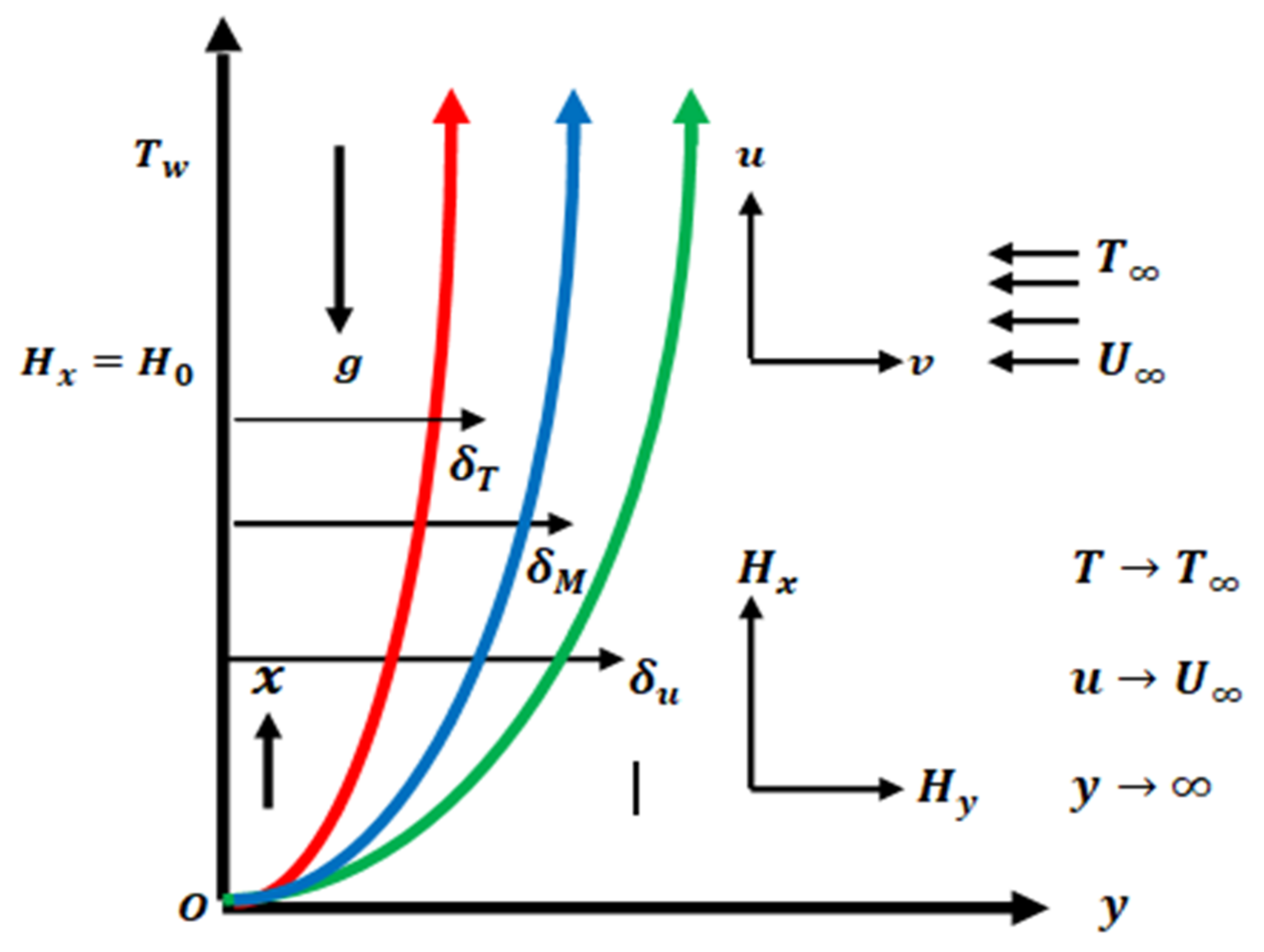
The present analysis addressed the thermal slip and radiation effects on electrically conducting flow phenomena of the convective heat transfer along the vertical symmetric heated surface with porous medium and magnetohydrodynamics impacts. The nonlinear-coupled PDE equations for the above fluid flow mechanism are formulated and then converted into non-similar formulations by applying an appropriate and well-known similarity transformation for integration. The final non-similar forms are integrated numerically by employing the Keller box scheme method. The transformed algebraic equations are plotted graphically and numerically on the MATLAB software package. The behavior of physical quantities such as velocity graph, magnetic field graph, and temperature graph along with their slopes, that is, skin friction, magnetic intensity, and transfer of heat under the effect of different parameters included in the flow model, is discussed.
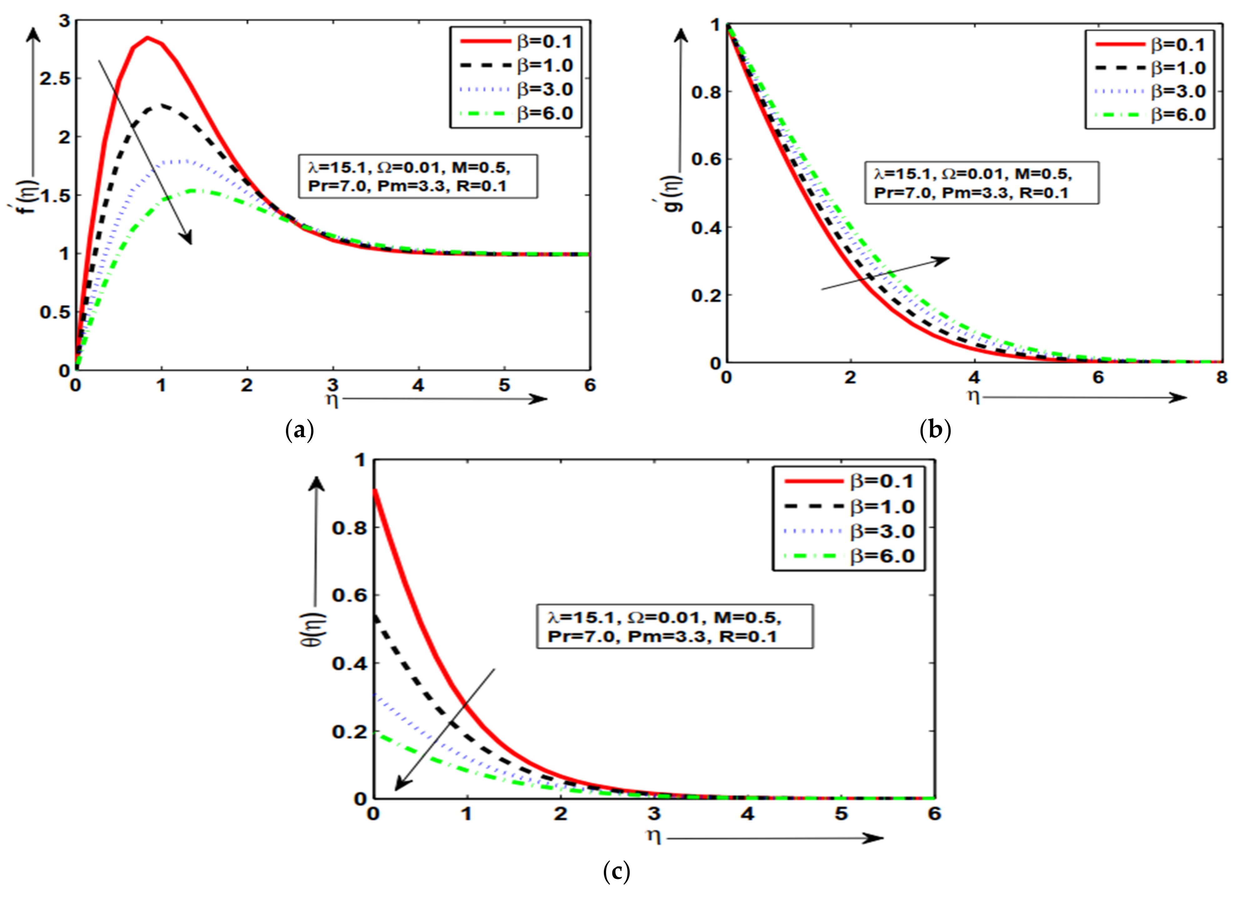
Figure 2a–c present the influence of thermalslip number with various values β = 0.1 , 1.0 , 3.0 , and 6.0 along the thermally and magnetized surface. To check the behavior of physical properties, the fluid velocity, magnetic field, and temperature of the fluid by keeping some constant variables havebeen deduced. In Figure 2a, it is obtained that velocity f η is increased at lower β = 0.1 , but the smaller quantity of f η velocity is obtained at large β = 6.0 . It is also noted that suitable variations are obtained at each value of β with a certain height and then approach asymptotically to the given boundary condition. Due to slip flow, the frictional resistance between the viscous fluid and the surface is eliminated, and the fluid velocity booststhe heat transfer and skin friction along the surface. It can be predicted that an increase in skin friction corresponds to a thinning of the velocity boundary layer. In Figure 2b, the magnetic effects in the fluid are maximum at larger β = 6.0 , and a smaller quantity is observed at lower β = 0.1 . The magnetic profile of the fluid obtained in suitable variation at each value of the β . It occurs because magnetic diffusion is reduced by increasing the magneticPrandtl number, which is responsible for the above-said phenomena. From Figure 2c, it is concluded that the slip temperature is maximum for a small value of β = 0.1 , but smaller quantity is explored at large β = 6.0 in a prominent way. The prominent variations in temperature θ η with prominent slip effects in the presence of λ = 15.1 . 
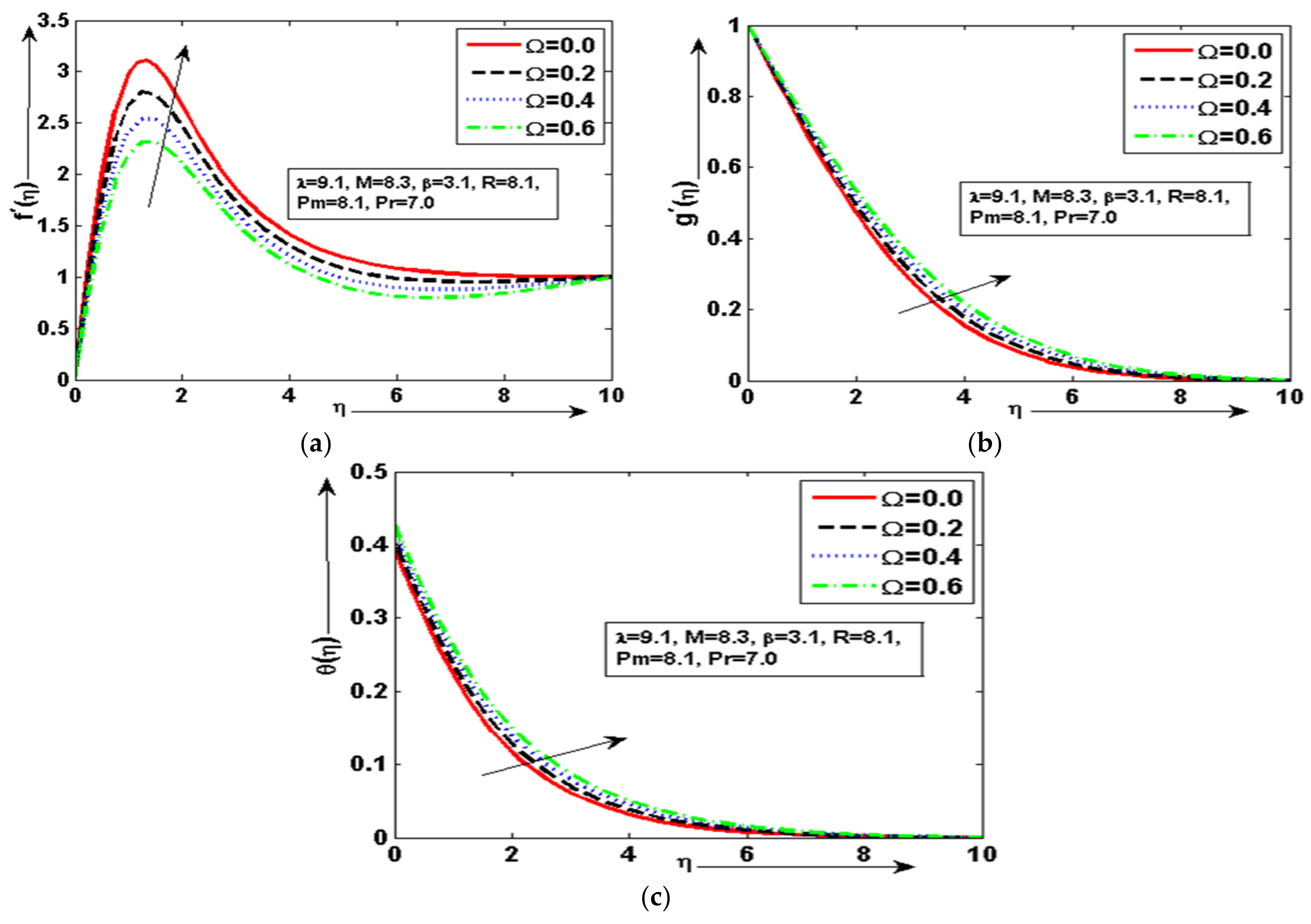
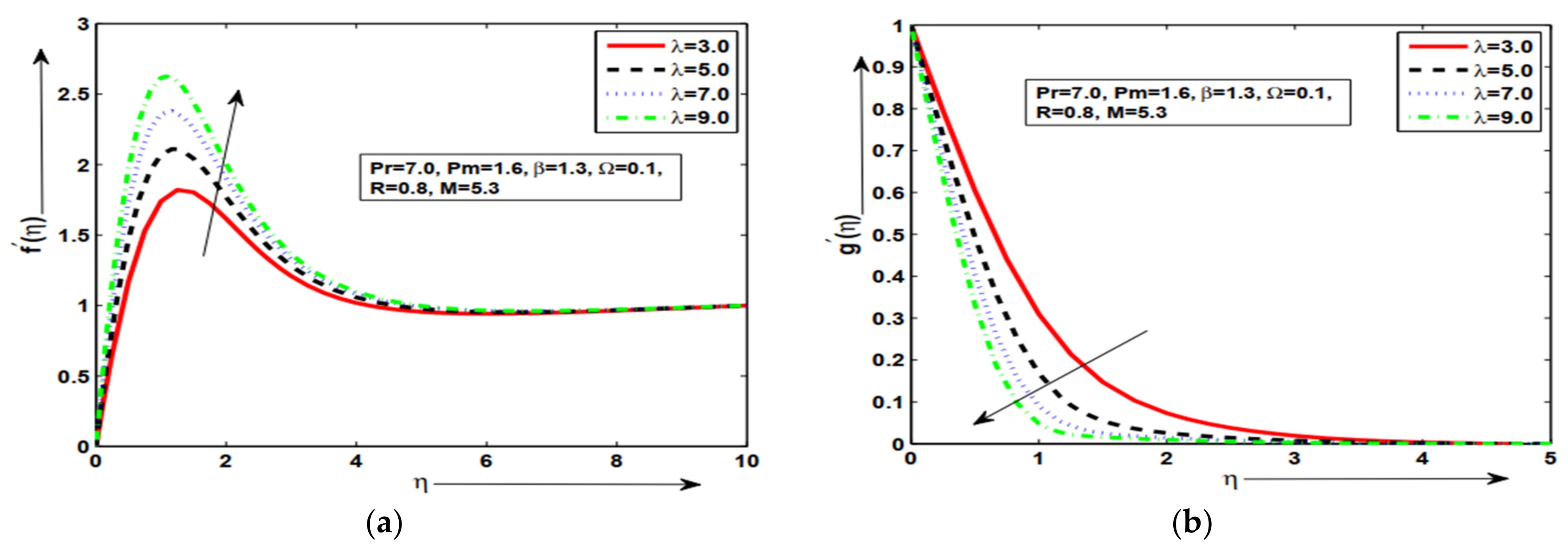
Figure 3a–c demonstrates the velocity profile, magnetic profile, and temperature θ η for various quantities of Ω = 0.0 ,   0.2 ,   0.4 , and 0.6 along magnetized heated geometry. In Figure 3a, the velocity graph is maximum at a smaller value of Ω   = 0.0 and minimum value at larger Ω = 0.6 with prominent amplitude and then approachesits given condition asymptotically. Increasing Ω means the medium is more porous, and the fluid permeability in the porous layer is increased and thus yields resistance in the fluid flow. In Figure 3b, it is concluded that the magnetic profile is increased at a higher value of Ω = 0.6 and is minimum at a smaller value of Ω = 0.0 with suitable variations. It occurs because the magnetic force parameter is the ratio of magnetic energy to kinetic energy, so with the increase in the magnetic force parameter P m , the magnetic energy is increased, while the kinetic energy is reduced. In Figure 3c, it is examined that the temperature profile is increased at a higher value of Ω = 0.6 but decreased at a smaller value of Ω = 0.0 
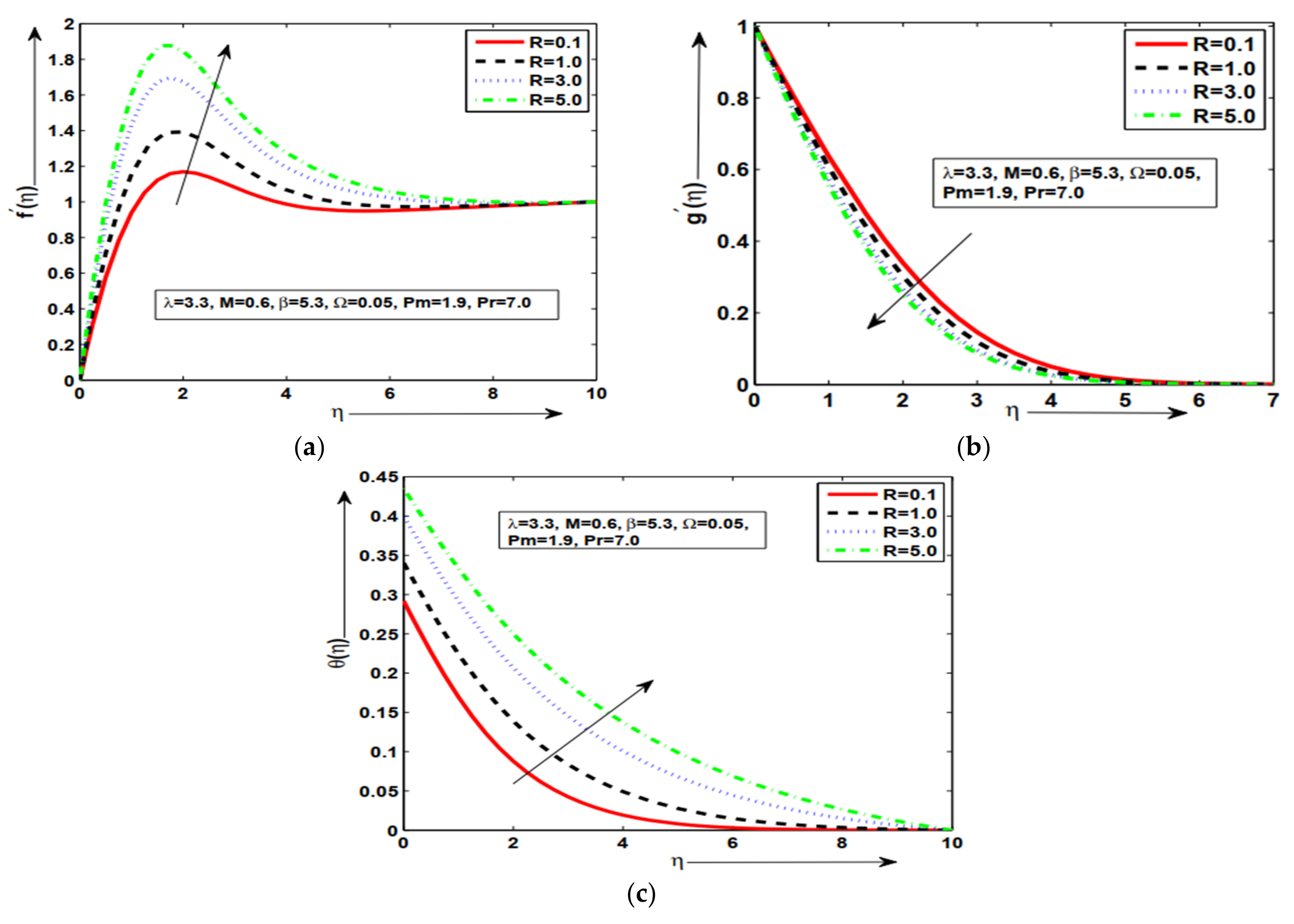
with better thermal slip. In Figure 4a, the maximum amplitude in velocity is obtained at larger R = 5.0 , and minimum velocity is obtained at lower R = 0.1 in the presence of magnetic force and strong magnetic Prandtl number. As the magnetic Prandtl number increases, the viscosity of fluid increases, and fluid becomes thicker and, consequently, the boundary layer thickness decreases. The prominent variations are obtained in the magnetic profile for each value of R in Figure 4b. The prominent thermalslip response is observed in temperature for each R in Figure 4c. An excellent and favorable slip phenomenonis observed in the temperature graph and presentssuitable behavior. The suitable variations are obtained in the velocity profile graph at each value of the R and then approached asymptotically to the given boundary condition. 
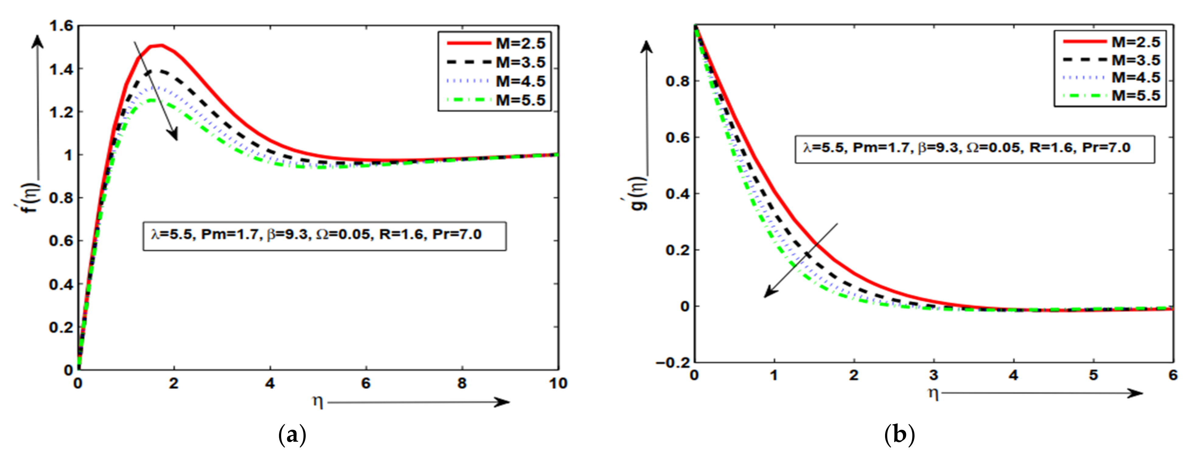
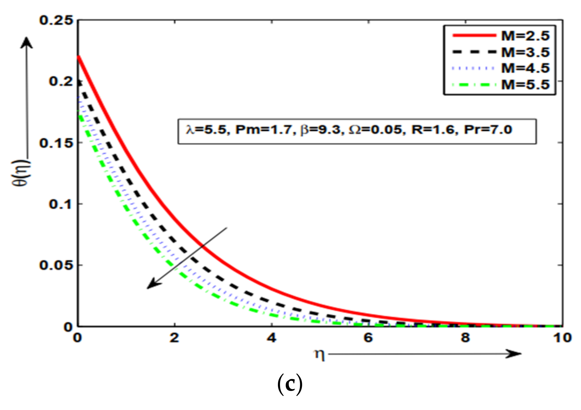
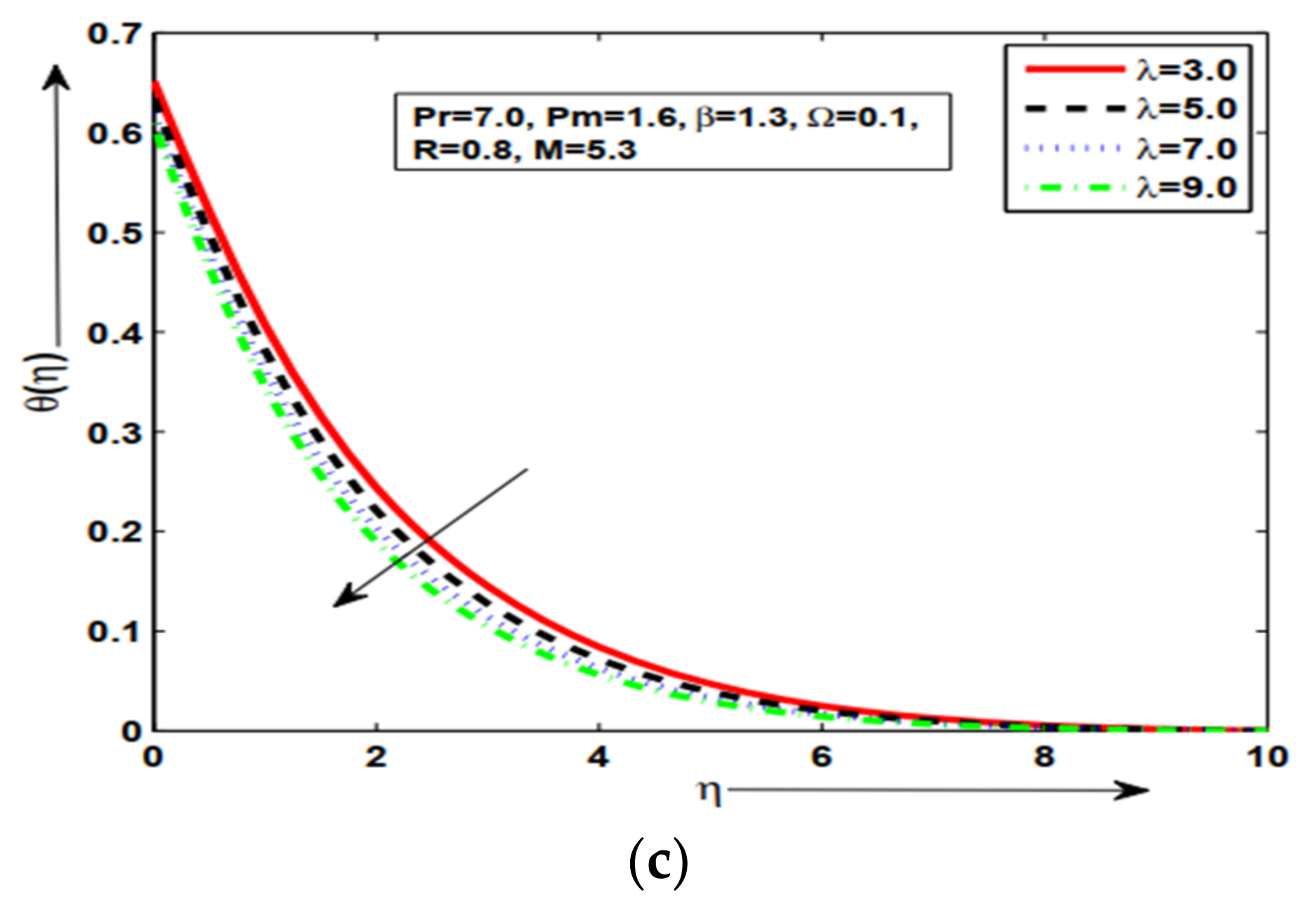
Figure 5a–c are presented the influence of magnetic force number M with various values M = 2.5 ,   3.5 ,   4.5 , and 5.5 along the heated surface. In Figure 5a, it is noticed that f η velocity is increased at a lower quantity of M = 2.5 but a smaller quantity of f η velocity is noticed at large M = 5.5 with suitable amplitude in the presence of thermal slip. This result was expected because an increase in M means an enhancement in the Lorentz forces, which opposes the flow and velocity of the fluid decreases. In Figure 5b, the magnetic profile is increased at the lower magnetic force parameter M = 2.5 , but the smaller quantity of magnetic profile is obtained at large M = 5.5 with prominent variations. In Figure 5c, it is concluded that the magneticforce effects in the fluid temperature aremaximum at M = 2.5 , and smaller quantity is found at large M = 5.5 with excellent thermalslip for the given phenomenon and approached to the given boundary conditions asymptotically. This behavior of the aforementioned variables supports the physical hypothesis that as the magnetic field grows stronger, more resistance is formed inside the fluid flow domain, which reduces the velocity distribution and improves the temperature profile. 
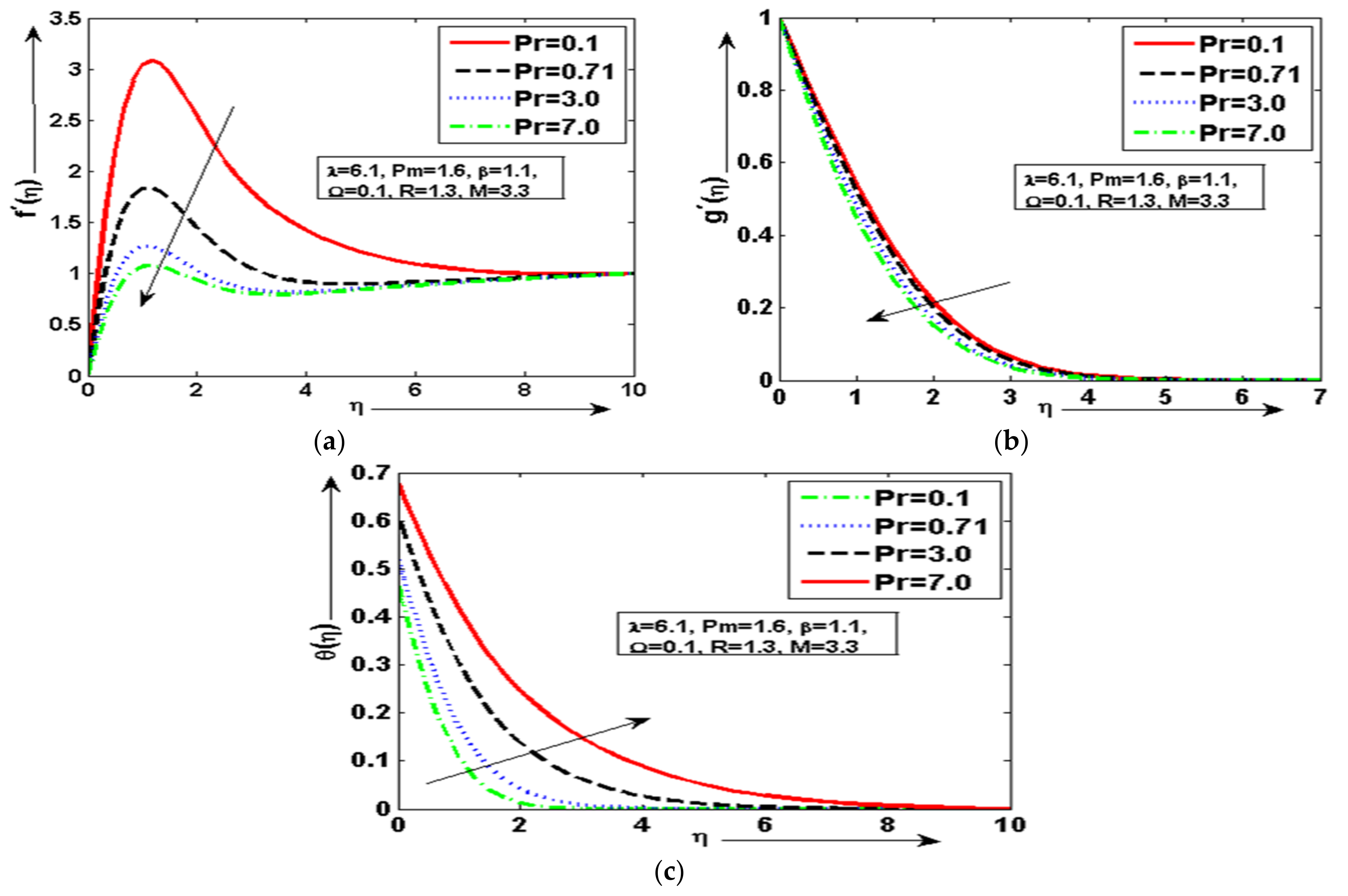
Figure 6a–c are presented against the various values of the Prandtl parameter P r = 0.1 , 0.71 , 3.0 and 7.0 along the magnetic plate. In Figure 6a, it is observed that the velocity f η is maximum with suitable amplitude response at a smaller value of Prandtl parameter P r = 0.1 , but the smaller quantity of f η is obtained at higher P r = 7.0 . It is also noted that f η profile shows suitable behavior along the surface of geometrical shape in the presence of mixed convection. In Figure 6b, the magnetic field profile showed suitable variations for each value of P r . From Figure 6c, it is concluded that the temperature profile along the surface of the given shape is maximum at a small value of P r = 0.1 while the temperature profile is minimum at a large value P r = 7.0 . This phenomenon is expected because an increase in P r tends to increase density variation with temperature, which enhances the buoyancy force. The thermal boundary layer thickness is reduced due to an increase in P r . The prominent thermal slip with suitable variations isobtained in the temperature graph at each value of P r . Due to the fluid’s poor thermal conductivity and decreased heat transfer as P r enhanced, the temperature of the fluid flow domain was reduced. In Figure 7a, it is noted that the velocity profile shows suitable amplitude effects along the heated plate in the presence of thermal slip and radiations. In Figure 7b, the magnetic profile is increased at lower mixedconvective parameter λ = 3.0 , but the smaller quantity of magnetic profile is obtained at large λ = 9.0 with prominent variations. In Figure 7c, it is noted that the temperature profile with excellent thermalslip is obtained for the given phenomenon and approachesthe given boundary conditions asymptotically. Physically, it was expected because larger values of λ correspond to stronger buoyancy forces, which leads to an increase the acceleration of fluid flow. Due to conducting phenomena, the magnetic effects are strongly observed exactly at the surface but far from the surface are zero for each value.
Table 1 presents the comparison of skin friction for three values of magnetic Prandtl number P m = 1.0 ,   10.0 ,   100.0 at the leading edge of the magnetized heated surface. In Table 1, Mehmood et al. [20] explored skin friction along a magnetized wedge, Ilyas et al. [21] obtained skin friction along a magnetized cone, but prominent results of skin friction are deduced in the current analysis along the magnetized heated surface. The values of skin friction are approximately matched with the previous results by using lower magnetic force M = 0.5 in the presence of porous medium and found suitable agreement in the present numerical results of skin friction. It can be seen that the maximum skin friction is obtained at lower P m = 1.0 , but lower skin friction is computed at maximum P m = 100.0 fromphysical point of view. This result was expected because an increase in M means an enhancement in the Lorentz forces, which opposes the flow and velocity of the fluid decreases. It was also expected because as the magnetic Prandtl number increases, the viscosity of fluid increases, and fluid becomes thicker, and consequently, the boundary layer thickness decreases. From Table 2, it is concluded that the skin friction f 0 is increased at smaller β = 0.1 , but the smaller quantity of skin friction is obtained at higher β = 6.0 with free/force convective parameter λ = 1.5 and magnetic force M . With the increase in value of M , the magnetic field becomes stronger along the surface, which is a clear indication that the Lorentz force is more effective in this case. It is noted that the magnetic intensity g 0 is maximum at small β = 0.1 , but the smaller quantity of magnetic intensity is examined at large β = 6.0 under the impact of porous parameter Ω = 0.8 . It is also depicted that the heat transfer is increased at lower β = 0.1 , but the smaller quantity of heat transfer is depicted at large β = 6.0 under the impact of maximum P r = 7.0 . Physically, it is possible because thermal conductivity decreases as P r increases, which has a lower magnitude of frictional forces between the viscous layers. Table 3 is indicated the influence of porous Ω numbers with diverse Ω = 0.1 , 0.4 , 0.7 and 1.0 along a vertical plate to check the behavior of physical properties the f 0 , g 0 and for θ 0 of the fluid while some parameters are fixed λ = 1.5 , M = 3.5 , and β = 1.1 . From Table 3, it is presumed that the f 0 is maximum at a smaller value of Ω = 0.1 , but the smaller quantity of skin friction is depicted at a higher quantity of Ω = 1.0 in the presence of temperatureslip number β = 1.1 . Increasing Ω means the medium is more porous, and the fluid permeability in the porous layer is increased and thus yields resistance in the fluid flow. However, due to the strong buoyancy number λ , which acts like a pressure gradient and dominatesover the resistance, skin friction is increased, and slight changes in heatand magnetic intensityare noted. It is depicted that the magnetic intensity is increased at smaller Ω = 0.1 , but the smaller quantity of magnetic intensity is explored at higher Ω = 1.0 in the presence of β = 1.1 . It is also mentioned that the heat transfer θ 0 is maximum at a lower value of Ω = 0.1 , but the small quantity of heat transfer is noticed at larger Ω = 1.0 in the presence of thermal slip parameter β = 1.1 . In Table 4, the skin friction is increased at larger R = 5.0 but reduced at lower R = 0.1 with temperatureslip and porous effects. The magnetic intensity is increased at higher R = 5.0 but decreased at lower R = 0.1 numerically, but the heat transfer is increased at R = 0.1 in the presence of a strong magnetic Prandtl number. The reason behind this is that increasing the value of P m is equivalent to decreasing magnetic diffusivity, and consequently, the strength of the magnetic field becomes loose. Physically, it is accurate to say that adding thermal radiation to a flow model raises the temperature of the fluid flow domain. Table 5 presents the comparison of heat transfer with Hirschhorn et al. [32], which verified the Table 2 results due to a strong magnetic field. The magnetized surface insulates the heat and reduces the excessive heating along the surface in the presence of a magnetic Prandtl number. In addition, the skin friction is maximum at lower thermal slip due to minimum friction resistance between the surface and fluid’s layers. So, the given results are valid and in suitable agreement froma physical point of view.

7. Conclusions

The current physical problem addressed the thermal slip and radiation effects on viscous flow phenomena of convective heat and magneticintensity transfer along vertical symmetric heated surfaces embedded in porous medium and magnetohydrodynamics impacts. In previous studies, the heat transfer characteristics along the non-magnetized shapes have been performed numerically. Due to excessive heating, these mechanisms are less interesting in engineering and industrial processes. To overcome this issue in the current analysis, the surface is magnetized, and the fluid is electrically conducting, which is responsible for reducing excessive heating along the surface. The nonlinear-coupled PDE equations for the above fluid flow mechanism are formulated with symmetric conditions normal to the heated surface and then converted into a non-similar formulation by applying an appropriate and well-known similarity transformation for integration. The final non-similar forms are numerically integrated by employing the Keller box scheme. The transformed algebraic equations are plotted graphically and numerically on the MATLAB software package. The main finding of the current analysis is to compute physical quantities such as velocity graph, magnetic field graph, and temperature plot along with their slopes, that is, skin friction, magnetic intensity, and heat transfer for different parameters included in the flow model. The comparison of Keller box analysis is computed with previous existing numerical results. Furthermore, the current issues have significant implications for the polymer industries, glass fiber production, petroleum production, fiber spinning, plastic film production, polymer sheet extraction, heat exchangers, catalytic reactors, and the production of electronic devices. The main findings are given below:
  • It is obtained that the velocity profile increased at β = 0.1 but decreased at β = 6.0 with a prominent variation. Due to slip flow, the frictional resistance between the viscous fluid and the surface is eliminated, and the fluid velocity booststhe heat transfer and skin friction along the surface;
  • The prominent variations are obtained in the magnetic profile for each value of R, and the prominent thermalslip response is observed in temperatures with a strong magnetic field. As the magnetic Prandtl number increases, the viscosity of fluid increases, and fluid becomes thicker, and consequently, the boundary layer thickness decreases;
  • It is concluded that the skin friction is increased at β = 0.1 , but the smaller quantity of skin friction is obtained at β = 6.0 withbuoyancy and magnetic force. With the increase in value of M , the magnetic field becomes stronger along the surface, which is a clear indication that the Lorentz force is more effective in this case;
  • It is presumed that skin friction is maximum at smaller Ω = 0.1 but minimum at higher Ω = 1.0 in the presence of temperature slip. Increasing Ω means the medium is more porous, and the fluid permeability in the porous layer is increased and thus yields resistance in the fluid flow;
  • Due to the strong buoyancy number λ , which acts like a pressure gradient and dominatesover the resistance, skin friction is increased, and slight changes in heatand magnetic intensityare noted.

Author Contributions

Conceptualization, Z.U. and M.B.; methodology, Z.U.; software, M.B.; validation, A.H., I.E.S. and Z.U.; formal analysis, I.E.S.; investigation, Z.U.; resources, I.E.S.; data curation, A.H.; writing—original draft preparation, M.B.; writing—review and editing, Z.U.; visualization, I.E.S.; supervision, Z.U.; project administration, I.E.S.; funding acquisition, I.E.S. All authors have read and agreed to the published version of the manuscript.

Funding

This research received no external funding.

Data Availability Statement

Not applicable.

Conflicts of Interest

The authors declare no conflict of interest.

Nomenclature

u , v Velocity along and normal to surface (m s−1) T Ambienttemperature (K)
H x , H y Magnetic coordinates of velocities in x , y direction (Tesla) R e x Renolds number
μ Dynamic viscosity (kg m−1 s−1) G r x Grashof number
H o Constant applied magnetic field N u x Nusselt number
T w Wall temperature (K) C f x Skin friction
q r Radiative heat flux M g x Magnetic intensity
D 1 Thermal slip factor D a x Local Darcy number
ν Kinematicalviscosity (m2 s−1)
Greek symbols
ρ Fluid density (kg m−3) κ Thermal conductivity parameter
g Gravity acceleration (m s−2) M Magnetic force parameter
β * Coefficient of thermalexpansion (K−1) λ Mixedconvective number
ν m Magnetic diffusivity (H m−1) θ Dimensionless temperature
α Thermaldiffusivity (m2 s−1) P m MagneticPrandtl parameter
TFluid temperature (K) PrPrandtl parameter
C p Specific heat (J kg−1 K−1) μ o Magnetic permeability
x Characteristic length η Similarity variable
U Free stream velocity (m s−1) ζ Thermal conductivity parameter
σ Electrical conductivity (s m−1) Κ permeability of porous medium
Ω Porous medium parameter β Thermal slip parameter
T o Constant temperature R Radiation parameter

Appendix A

From the given stream function formulation and similarity variables Equations (7) and (8),
u = U f ,   v = U y f 2 x U ν f 2 U ν x ,   u x = U 2 f y 2 ν x 2 ν x U ,   v y = U 2 f y 2 ν x 2 ν x U
H x = H o g ,   H y = H o y g 2 x H o ν g 2 U ν x ,   u y = U f U ν x ,   2 u y 2 = U 2 f ν x
H x y = U g U ν x ,   2 u y 2 = H o g U ν x ,   H x x = H o g y U 8 ν x 2 ν x U ,   H y y = H o g y U 8 ν x 2 ν x U
T = T + T o x θ ,   T x = T o θ x 2 U y θ 2 ν x 3 ν x U ,   T y = T o θ x U ν x ,   2 T y 2 = T o θ U ν x 2
By using Equations (A1)–(A4), the ODEs are given in Equations (9)–(11), and boundary conditions are given in Equation (12).

References

  1. Mukhopadhyay, S. Effect of thermal radiation on unsteady mixed convection flow and heat transfer over a porous stretching surface in porous medium. Int. J. Heat Mass Transf. 2009, 52, 3261–3265. [Google Scholar] [CrossRef]
  2. Sarada, K.; Gowda, R.J.P.; Sarris, I.E.; Kumar, R.N.; Prasannakumara, B.C. Effect of magnetohydrodynamics on heat transfer behaviour of a non-Newtonian fluid flow over a stretching sheet under local thermal non-equilibrium condition. Fluids 2021, 6, 264. [Google Scholar] [CrossRef]
  3. Abbas, A.; Shafqat, R.; Jeelani, M.B.; Alharthi, N.H. Significance of Chemical Reaction and Lorentz Force on Third-Grade Fluid Flow and Heat Transfer with Darcy–Forchheimer Law over an Inclined Exponentially Stretching Sheet Embedded in a Porous Medium. Symmetry 2022, 14, 779. [Google Scholar] [CrossRef]
  4. Kumar, A. Numerical study of effect of induced magnetic field on transient natural convection over a vertical cone. Alex. Eng. J. 2016, 55, 1211–1223. [Google Scholar] [CrossRef] [Green Version]
  5. Bhattacharyya, K.; Mukhopadhyay, S.; Layek, G.C. Similarity solution of mixed convective boundary layer slip flow over a vertical plate. Ain Shams Eng. J. 2013, 4, 299–305. [Google Scholar] [CrossRef] [Green Version]
  6. Muhammad, A.; Chamkha, A.J.; Iqbal, S.; Ahmad, M. Effects of temperature-dependent viscosity and thermal conductivity on mixed convection flow along a magnetized vertical surface. Int. J. Numer. Methods Heat Fluid Flow 2016, 26, 1580–1592. [Google Scholar] [CrossRef] [Green Version]
  7. Chawla, S.S. Magnetohydrodynamic oscillatory flow past a semi-infinite flat plate. Int. J. Non-Linear Mech. 1971, 6, 117–134. [Google Scholar] [CrossRef]
  8. Cheng, W.; Liu, Y.L.; Yang, F. A Modified Regularization Method for a Spherically Symmetric Inverse Heat Conduction Problem. Symmetry 2022, 14, 2102. [Google Scholar] [CrossRef]
  9. Chen, J.; Du, W.; Kong, B.; Wang, Z.; Cao, J.; Wang, W.; Yan, Z. Numerical Investigation on the Symmetric Breakup of Bubble within a Heated Microfluidic Y-Junction. Symmetry 2022, 14, 1661. [Google Scholar] [CrossRef]
  10. Garia, R.; Rawat, S.K.; Kumar, M.; Yaseen, M. Hybrid nanofluid flow over two different geometries with Cattaneo–Christov heat flux model and heat generation: A model with correlation coefficient and probable error. Chin. J. Phys. 2021, 74, 421–439. [Google Scholar] [CrossRef]
  11. Yaseen, M.; Rawat, S.K.; Kumar, M. Cattaneo–Christov heat flux model in Darcy–Forchheimer radiative flow of MoS2–SiO2/kerosene oil between two parallel rotating disks. J. Therm. Anal. Calorim. 2022, 147, 10865–10887. [Google Scholar] [CrossRef]
  12. Yaseen, M.; Rawat, S.K.; Shafiq, A.; Kumar, M.; Nonlaopon, K. Analysis of Heat Transfer of Mono and Hybrid Nanofluid Flow between Two Parallel Plates in a Darcy Porous Medium with Thermal Radiation and Heat Generation/Absorption. Symmetry 2022, 14, 1943. [Google Scholar] [CrossRef]
  13. Yaseen, M.; Rawat, S.K.; Kumar, M. Falkner–Skan Problem for a Stretching or Shrinking Wedge with Nanoparticle Aggregation. J. Heat Transf. 2022, 144, 102501. [Google Scholar] [CrossRef]
  14. Agrwal, A.; Kasana, V. [Fesipmim] Cl as highly efficient and reusable catalyst for solventless synthesis of dihydropyridine derivatives through Hantzsch reaction. J. Chem. Sci. 2020, 132, 67. [Google Scholar] [CrossRef]
  15. Agrwal, A.; Kumar, V.; Kasana, V. Preparation and application of highly efficient and reusable TBAPIL@ Si (CH2)3@nano-silica-based nano-catalyst for preparation of benzoxanthene derivatives. J. Iran. Chem. Soc. 2021, 18, 2583–2595. [Google Scholar] [CrossRef]
  16. Chaudhary, P.; Agrwal, A.; Sharma, D.K.; Kumar, V. Synthesis and screen-printing of sol-gel developed pure and Yb-doped ZnO films towards optoelectronic analysis. J. Sol-Gel Sci. Technol. 2022, 104, 425–433. [Google Scholar] [CrossRef]
  17. Chamkha, A.J. On laminar hydromagnetic mixed convection flow in a vertical channel with symmetric and asymmetric wall heating conditions. Int. J. Heat Mass Transf. 2002, 45, 2509–2525. [Google Scholar] [CrossRef]
  18. Valentino, M.; Tran, L.; Ricklick, M.; Kapat, J. Comparison of heat transfer and friction augmentation for symmetric and non-symmetric wedge turbulators on two opposite walls. In Proceedings of the 47th AIAA/ASME/SAE/ASEE Joint Propulsion Conference & Exhibit, San Diego, CA, USA, 31 July–3 August 2011; p. 6021. [Google Scholar]
  19. Sinanoglu, A.; Karaca, I.Y.; Tokmak, F.; Senlik, T. Existence of three symmetric positive solutions for a second-order multi-point boundary value problem on time scales. Adv. Differ. Equ. 2014, 2014, 81. [Google Scholar] [CrossRef] [Green Version]
  20. Mahmood, M.; Asghar, S.; Hossain, M.A. Hydromagnetic flow of viscous incompressible fluid past a wedge with permeable surface. ZAMM-J. Appl. Math. Mech. Z. Für Angew. Math. Mech. Appl. Math. Mech. 2009, 89, 174–188. [Google Scholar] [CrossRef]
  21. Ilyas, A.; Ashraf, M.; Rashad, A.M. Periodical analysis of convective heat transfer along electrical conducting cone embedded in porous medium. Arab. J. Sci. Eng. 2021, 47, 8177–8188. [Google Scholar] [CrossRef]
  22. Al-Mdallal, Q.; Prasad, V.R.; Basha, H.T.; Sarris, I.; Akkurt, N. Keller box simulation of magnetic pseudoplastic nano-polymer coating flow over a circular cylinder with entropy optimisation. Comput. Math. Appl. 2022, 118, 132–158. [Google Scholar] [CrossRef]
  23. Islam, M.T. Heat Transfer through Parallel Plate Microchannels at Symmetric and Asymmetric Constant Wall Temperature. Acad. J. Appl. Math. Sci. 2018, 4, 22–33. [Google Scholar]
  24. Wang, C.Y. Boundary layers on rotating cones, discs and axisymmetric surfaces with a concentrated heat source. Acta Mech. 1990, 81, 245–251. [Google Scholar] [CrossRef]
  25. Mukhopadhyay, S.; Mondal, I.C.; Chamkha, A.J. Casson fluid flow and heat transfer past a symmetric wedge. Heat Transf. Asian Res. 2013, 42, 665–675. [Google Scholar] [CrossRef]
  26. Ullah, Z.; Ashraf, M.; Sarris, I.E.; Karakasidis, T.E. The Impact of Reduced Gravity on Oscillatory Mixed Convective Heat Transfer around a Non-Conducting Heated Circular Cylinder. Appl. Sci. 2022, 12, 5081. [Google Scholar] [CrossRef]
  27. Murdock, J.W. The solution of sharp-cone boundary-layer equations in the plane of symmetry. J. Fluid Mech. 1972, 54, 665–678. [Google Scholar] [CrossRef]
  28. Charvátová, H.; Janáčová, D.; Kolomazník, K. Study of non-stationary Heat conduction in a Plane Plate for Symmetric and Asymmetric Problem. WSEAS Trans. Heat Mass Transf. 2011, 6, 11–20. [Google Scholar]
  29. Aldoss, T.; Al-Nimr, M.; Jarrah, M.; Al-Sha, B. Magnetohydrodynamic mixed convection from a vertical plate embedded in a porous medium. Numer. Heat Transf. Part A Appl. 1995, 28, 635–645. [Google Scholar] [CrossRef]
  30. Ullah, Z.; Yasmin, S.; Younis, J.; Abdullah, A.; Abbas, S.; Shah, A. Dynamics of Unsteady Flow of Chemically Reactive Upper-Convected Maxwell Fluid with Temperature-Dependent Viscosity: Keller Box Analysis. Math. Probl. Eng. 2022, 2022, 5344759. [Google Scholar] [CrossRef]
  31. Rees, D.A.S.; University of Bath, Bath, UK. The numerical solution of ordinary and partial differential equations using the Keller-box method. Private communication, 1998. [Google Scholar]
  32. Hirschhorn, J.; Madsen, M.; Mastroberardino, A.; Siddique, J.I. Magnetohydrodynamic boundary layer slip flow and heat transfer of power law fluid over a flat plate. J. Appl. Fluid Mech. 2015, 9, 11–17. [Google Scholar] [CrossRef]
  33. Sarada, K.; Gamaoun, F.; Abdulrahman, A.; Paramesh, S.O.; Kumar, R.; Prasanna, G.D.; Gowda, R.P. Impact of exponential form of internal heat generation on water-based ternary hybrid nanofluid flow by capitalizing non-Fourier heat flux model. Case Stud. Therm. Eng. 2022, 38, 102332. [Google Scholar]
  34. Kumar, R.N.; Gamaoun, F.; Abdulrahman, A.; Chohan, J.S.; Gowda, R.P. Heat transfer analysis in three-dimensional unsteady magnetic fluid flow of water-based ternary hybrid nanofluid conveying three various shaped nanoparticles: A comparative study. Int. J. Mod. Phys. B 2022, 36, 2250170. [Google Scholar] [CrossRef]
  35. Sunitha, M.; Gamaoun, F.; Abdulrahman, A.; Malagi, N.S.; Singh, S.; Gowda, R.J.; Gowda, R.P. An efficient analytical approach with novel integral transform to study the two-dimensional solute transport problem. Ain Shams Eng. J. 2022, 101878. [Google Scholar] [CrossRef]
  36. Asogwa, K.K.; Alsulami, M.D.; Prasannakumara, B.C.; Muhammad, T. Double diffusive convection and cross diffusion effects on Casson fluid over a Lorentz force driven Riga plate in a porous medium with heat sink: An analytical approach. Int. Commun. Heat Mass Transf. 2022, 131, 105761. [Google Scholar] [CrossRef]
  37. Punith Gowda, R.J.; Sarris, I.E.; Naveen Kumar, R.; Kumar, R.; Prasannakumara, B.C. A Three-Dimensional Non-Newtonian Magnetic Fluid Flow Induced due to Stretching of the Flat Surface with Chemical Reaction. J. Heat Transf. 2022, 144, 113602. [Google Scholar] [CrossRef]
  38. Punith Gowda, R.J.; Naveen Kumar, R.; Jyothi, A.M.; Prasannakumara, B.C.; Sarris, I.E. Impact of binary chemical reaction and activation energy on heat and mass transfer of marangoni driven boundary layer flow of a non-Newtonian nanofluid. Processes 2021, 9, 702. [Google Scholar] [CrossRef]
Figure 1. Coordinate system and flow geometry.
Symmetry 14 02421 g001
Figure 2. (ac). The geometric profiles of f η , g η , and θ η against β .
Symmetry 14 02421 g002
Figure 3. (ac). The geometric profiles of f η , g η , and θ η against Ω .
Symmetry 14 02421 g003
Figure 4. (ac). The geometric profiles of f η ,   g η , and θ η against R.
Symmetry 14 02421 g004
Figure 5. (ac). The geometric profiles of f η ,   g η , and θ η against M .
Symmetry 14 02421 g005aSymmetry 14 02421 g005b
Figure 6. (ac). The geometric profiles of f η ,   g η , and θ η against Pr.
Symmetry 14 02421 g006
Figure 7. (ac). The geometric profilesof f η ,   g η , and θ η against λ .
Symmetry 14 02421 g007aSymmetry 14 02421 g007b
Table 1. Numerical results for f 0 skin friction for various values of P m = 1.0 ,   10.0 ,   100.0   for β = 0.1 ,   M = 0.5 ,   P r = 7.0 ,   λ = 0.1   a t the leading edge.
P m Mehmood et al. [20]Ilyas et al. [21]Present Analysis
1.0 0.3148 0.3122   0.3193
10.0 0.3151 0.3137 0.3180
100.0 0.3156 0.3149 0.3041
Table 2. Numerical results for f 0 , g 0 and for θ 0 for various values of β = 0.1 ,   1.0 ,   3.0 ,   6.0 , while other parameters are fixed.
β = f 0 g 0 θ 0
0.1 7.948792987522230 0.469004024822659 0.872763001306980
1.0 5.444255951510843 0.411585485704276 0.459271245066785
3.0 3.650283616517952 0.363853736639147 0.230932235434102
6.0 2.679220347371918 0.333775556097965 0.134087127559919
Table 3. Numerical results for f 0 , g 0 and for θ 0 for various values of Ω = 0.1 ,   0.4 ,   0.7 ,   1.0 , while other parameters are fixed.
Ω . f 0 g 0 θ 0
0.1 1.570888903060684 0.250664877643679 0.287615619132488
0.4 1.020219932907417 0.221789130911155 0.257375444745247
0.7 0.693273907560712 0.198738070735411 0.231620888575782
1.0 0.504794793668375 0.181464431569163 0.211274951578891
Table 4. Numerical results for f 0 , g 0 and for θ 0 for various values of R = 0.1 ,   1.0 ,   3.0 ,   5.0 , while other parameters are fixed.
R f 0 g 0 θ 0
0.1 1.383648476977060 0.376890740587770 0.133671961466489
1.0 1.694272623828378 0.412795831386895 0.124460477822591
3.0 2.091203704461853 0.454926644631236 0.113299983497299
5.0 2.335649688218721 0.478692890887229 0.106502575270043
Table 5. Comparison of numerical results for θ 0 Nusselt number for various values of β = 0.0 ,   0.3 ,   0.6   for P m = 3.3 ,   M = 0.1 ,   P r = 7.0 ,   λ = 1.8 ,   R = 0.1 ,   Ω = 0.01 along the magnetized plate.
β Hirschhorn et al. [32]Present Analysis
0.00.347680.34174
0.30.314840.32909
0.60.287670.31976
Publisher’s Note: MDPI stays neutral with regard to jurisdictional claims in published maps and institutional affiliations.

