Article

Research on the Calculation Model and Control Method of Initial Supporting Force for Temporary Support in the Underground Excavation Roadway of Coal Mine

1
School of Mechanical Electronic and Information Engineering, China University of Mining & Technology (Beijing), Beijing 100083, China
2
Xi’an Institute of Electromechanical Information Technology, Xi’an, No. 16, Zhangba 2nd Road, High-Tech Zone, Xi’an 710065, China
3
School of Vehicle and Transportation Engineering, Tsinghua University, Beijing 100084, China
*
Author to whom correspondence should be addressed.
Submission received: 13 August 2023 / Revised: 8 September 2023 / Accepted: 28 September 2023 / Published: 5 October 2023
(This article belongs to the Special Issue Computational Mathematics in Engineering and Applied Science)

Abstract

:
This paper proposes a temporary support system for improving the efficiency and safety of underground roadway excavation in coal mines. Firstly, this study establishes a calculation model for the initial supporting force of the excavation of roadway temporary support and a gray system-based automatic prediction model for the initial supporting force level, based on the mechanism of temporary support controlling the roof. These models enable the prediction of the required initial supporting force at different locations along the roadway’s temporary support area, thereby providing a basis for controlling the initial supporting force of the temporary support system. To achieve efficient and adaptive control of the initial supporting force of temporary supports at different locations, this study designs a support force controller based on Simulated Annealing Particle Swarm Optimization Proportional-Integral-Derivative (SAPSO-PID). This study establishes a mathematical model for the hydraulic cylinder pressure system controlled by the temporary support overflow valve and conducts a stability analysis and model verification. The study constructs a simulation control system for the initial supporting force based on SAPSO-PID using the combined simulation platform of AMESim and Matlab. The simulation results demonstrate that the proposed support force control system efficiently achieves adaptive control of the initial supporting force of temporary supports. An experimental system in the underground roadway of a coal mine is constructed to validate the results of the simulation analysis.

1. Introduction

The extraction of coal in underground mines presents a significant risk to the safety and well-being of miners [1]. Miners persistently encounter one of the highest level of occupational hazards among various industrialized nations globally. Achieving sustainable development in industrialized nations can be facilitated through the implementation of automation technologies in mining operations [2,3]. According to the International Energy Agency, global coal consumption has increased by 65% since 2000, with coal accounting for over 40% of all energy generation [4]. While coal is expected to continue its dominant role in the energy sector, the mining of deeper coal seams (below −800 m) has become increasingly challenging due to the depletion of shallow buried reserves [5]. The excavation of coal mine roadways is a critical and hazardous process in underground coal mines. The difficult excavation conditions and practical challenges faced during this operation severely hinder the development of intelligent and rapid roadway excavation techniques [6]. Therefore, achieving intelligent and efficient tunneling of roadways is imperative for ensuring high production rates and efficiency in coal mines, and is also an urgent research priority.
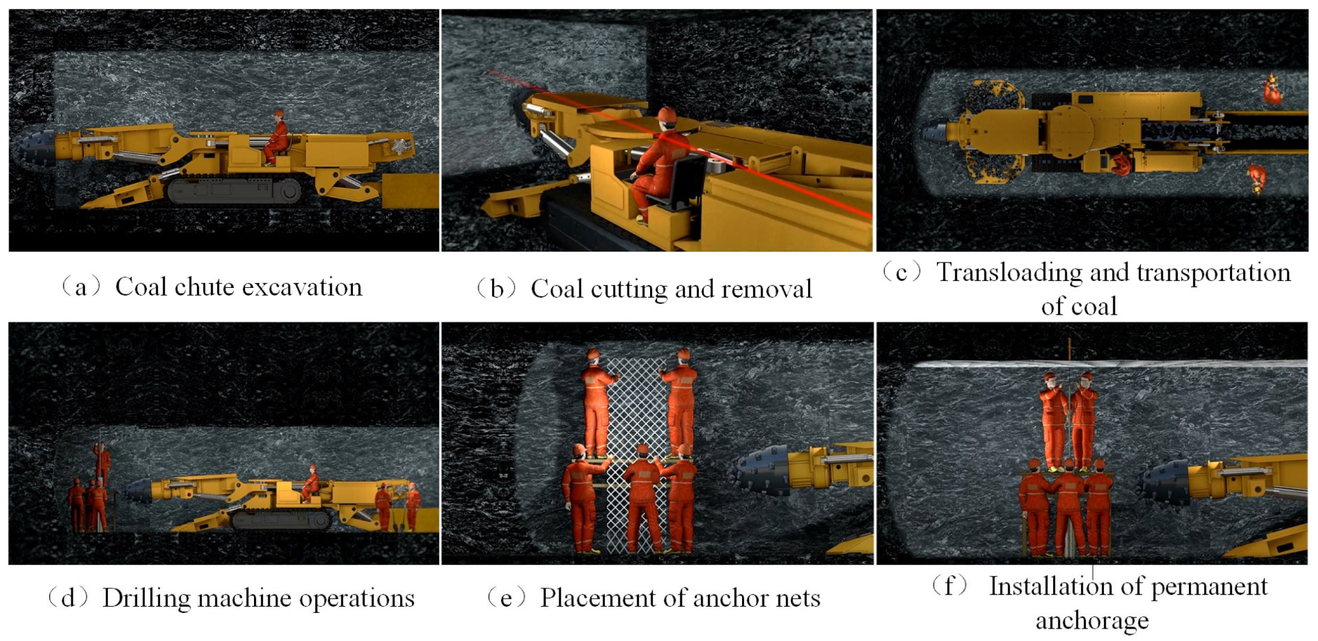
Restricted by the complex operating environment of roadways, the current excavation process in coal mines follows a step-by-step approach, as depicted in Figure 1. This process consists of six major steps: coal chute excavation, coal cutting and removal, transloading and transportation of coal, drilling machine operations, placement of anchor nets, and installation of permanent anchorage. However, the current excavation process is characterized by the use of numerous pieces of equipment that are independent of each other, a lack of coordination, fragmented workflow, and manual sequential operations. Particularly, the support process that follows excavation is time-consuming and labor-intensive, and the excavation and support operations cannot be conducted in a continuous manner as they rely heavily on manual intervention. Consequently, this situation hampers excavation efficiency and the rate of successful initiation [7,8,9].
This paper addresses the issues associated with the existing sequential excavation process by proposing the design of temporary supports for excavation lanes and establishing a designated area for temporary support, referred to as the advanced support area. This approach enables a new parallel operation process that encompasses excavation, temporary support, drilling, and anchoring. 
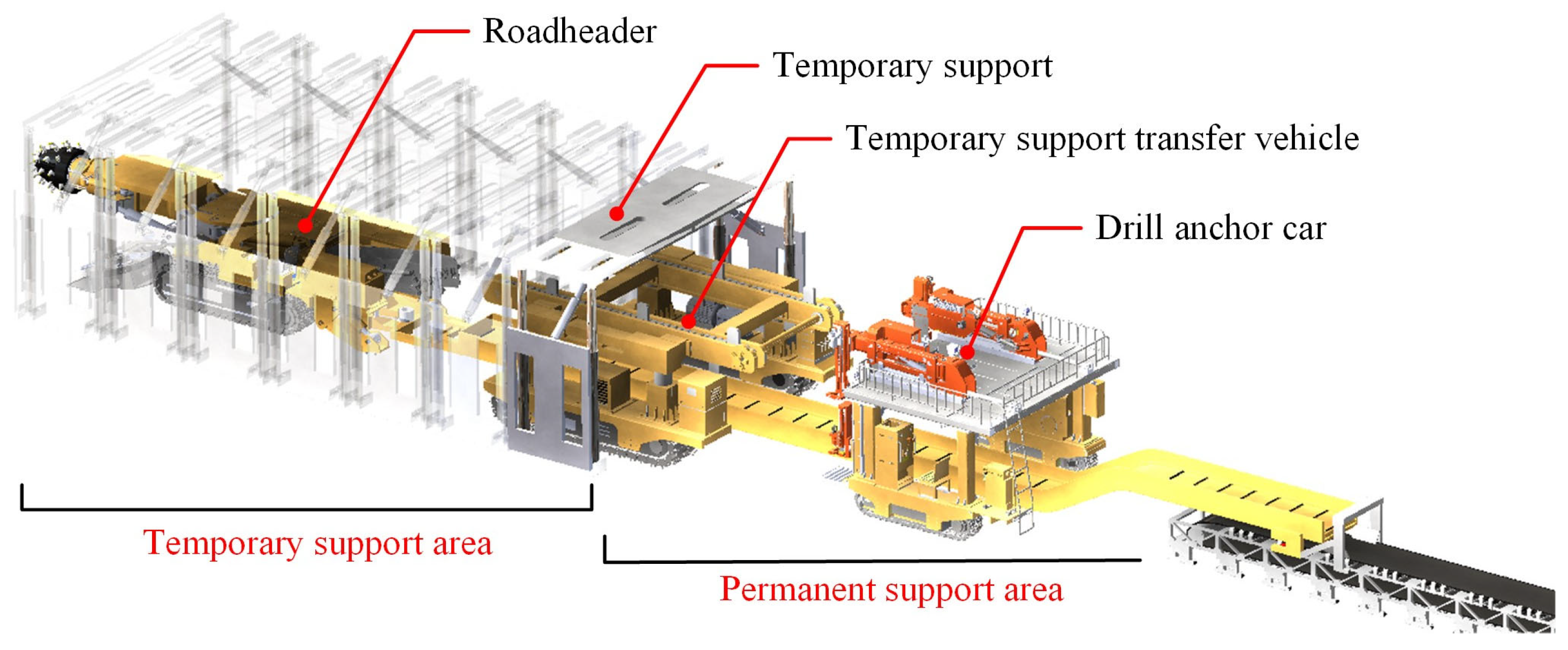
Figure 2 illustrates the complete set of equipment required for excavating, supporting, and anchoring, as well as the new parallel process. This set includes a roadheading machine, temporary support, transfer vehicle, drilling and anchoring machine, and other auxiliary components. The operational process of the parallel coal chute excavation, support, and anchoring is as follows: the roadheading machine, positioned ahead of the coal tunneling workface, performs slotting and section cutting, while the temporary support transfer vehicle moves the temporary support to the front of the roadheading. Subsequently, the temporary support transfer vehicle returns, allowing the drilling and anchoring machine to carry out permanent anchorage. By repeating these steps, the parallel and coordinated operation of excavation, temporary support, and anchoring is achieved, thereby enhancing excavation efficiency [10].
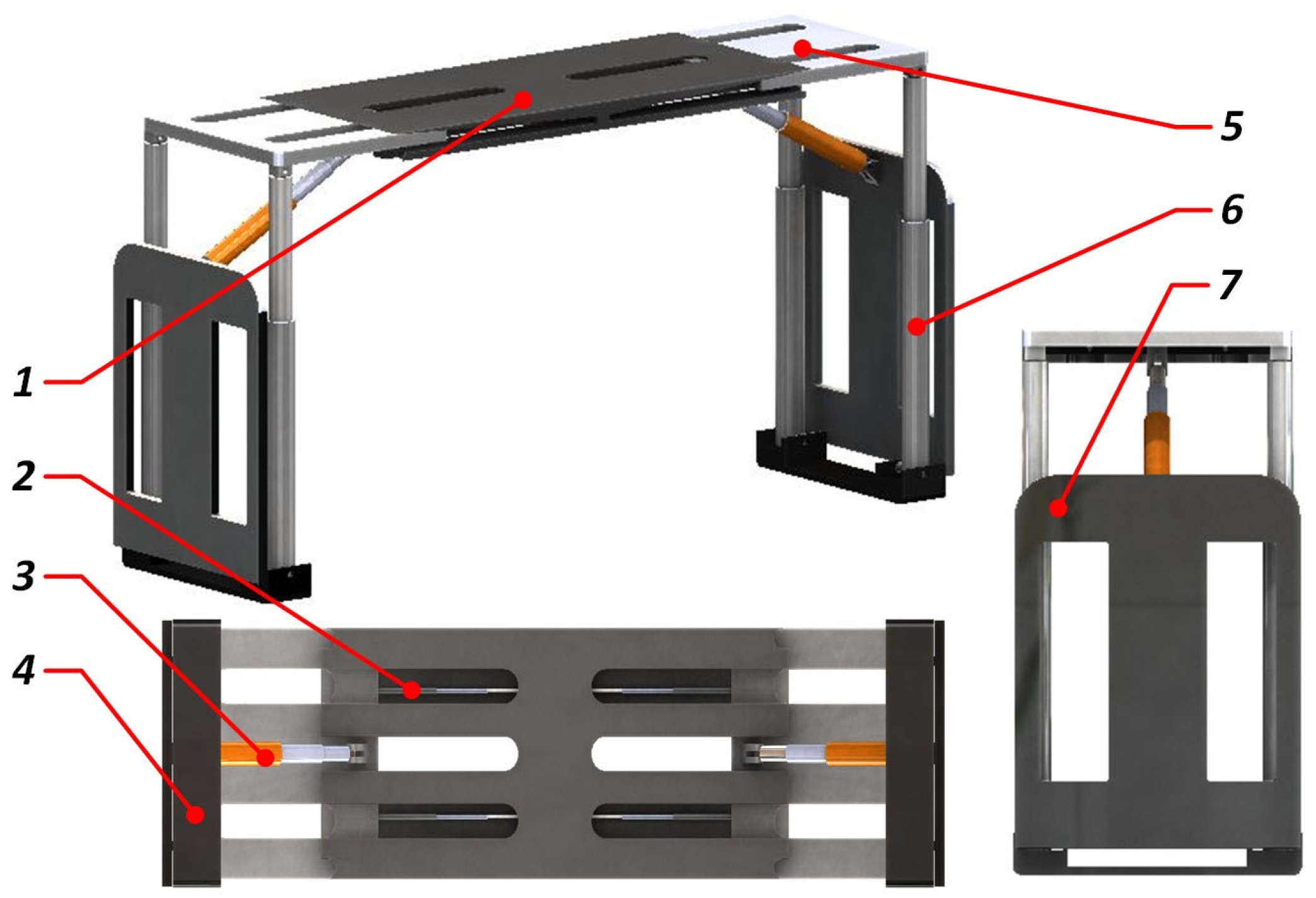
The temporary support structure of the tunneling roadway is depicted in Figure 3, comprising the roof beam, transverse expansion beam, guard plate, base, balance jack, and support column. The roof beam is connected to the transverse telescopic beam using a pushing cylinder, while the guard plate is hinged with the balancing jack. The support column, on the other hand, is hinged to the transverse telescopic beam via a ball vice. As a supporting element, the support roof beam directly contacts the roof plate of the roadway and actively bears the load of the surrounding rock. Likewise, the slide shoe base establishes direct contact with the roadway floor, allowing it to withstand the pressure exerted by the surrounding rock load transmitted through the support column and subsequently transferring that pressure to the roadway floor.
During temporary support of tunneling roadways, the roof support can be classified into three stages: initial bracing and increasing resistance, passive increasing resistance, and constant resistance overflowing. The initial bracing and increasing resistance stage involves active support of the roadway roof, with the support force during this stage referred to as the initial bracing force. The initial bracing force is a crucial parameter in temporary support, playing a significant role in roof control [11]. In tunneling roadway temporary support, the magnitude of the initial bracing force exerted by temporary brackets affects the effectiveness of roof plate support. Insufficient initial bracing force reduces support safety and increases the risk of early roof separation. Conversely, a high initial bracing force enables quick resistance buildup when pressure is exerted on the roof, minimizing top sinking and reducing the likelihood of roof collapse at the working face. However, excessive initial bracing force can lead to the coal tunnel roof crushing, causing secondary damage and escalating safety risks [10,12]. Therefore, it is particularly important for research on tunnel excavation to determine the appropriate initial support force for temporary supports and establish an efficient initial support force control system. Currently, research on temporary bracing for excavation in underground coal mines is still in its early stages. The research primarily focuses on optimizing the structural design of temporary bracing. Liu et al. [13] developed a coupled model of temporary support-roof plate system, suggested a temporary brace for roadways, and investigated its supportive performance. Ding et al. [14] examined the design of a self-moving temporary brace for roadways. Ma et al. [15] utilized the Optimal Space-Filling (OSF) method to optimize the structure of temporary support devices for coal mines, which plays a crucial role in the design of rectangular braces. Xue et al. [16,17] introduced a control method for the support force of temporary braces based on neural network PID. They obtained the input curve of surrounding rock pressure variation through simulation fitting using FLAC3D 6.0 software. Additionally, they developed a neural network PID control algorithm for adaptively tracking the control of surrounding rock pressure in the support force.
Several researchers have investigated the initial bracing force and regulatory methods for temporary bracing in coal mining faces, yielding useful research findings that can serve as references. Wang et al. [11] introduced the design principle of non-equal strength coupling support and temporary support, known as “low initial support, high work resistance,” which enhanced the adaptability of temporary support to high-stress and impact-prone roadways. Cheng et al. [18] developed an intelligent sensing system to monitor the state of braces and roofs. This system utilizes extensive monitoring data gathered from electro-hydraulically controlled hydraulic braces, enabling the analysis of the interaction between brace working resistance and surrounding rock and roof pressures. Ding et al. [19] devised a novel type of overrun support for general mining roadways, featuring high adaptability, support strength, and ample operating space. This design caters to the challenging conditions found in deep general mining working faces, characterized by severely unbalanced distribution of excavation, support, and anchorage duration. The authors further examined the stress–strain characteristics of the overrun support. Zhao et al. [20] presented a technique for the sectional adjustment of the hydraulic support setting load, aimed at pre-cracking and weakening coal walls in the context of comprehensive mining operations in hard and thick coal seams. Chen et al. [21] conducted a study on maintaining the spatial position of support braces during coal mining operations. However, their research did not encompass the calculation of initial bracing force or the investigation of regulatory systems.
A literature review revealed that no scholar has conducted a systematic study on the calculation and control of the initial support force of temporary support in underground coal mine roadways. In order to promote the safety and efficiency of temporary support, based on the above analysis, this study takes the control of the initial support force of roadway temporary support as the research object. It establishes a calculation model for the initial support force of underground coal mine roadway temporary support and a gray system automatic prediction model for the initial support force level, which achieves the demand prediction of the initial support force at different positions in the temporary support zone of the roadway. A controller for the initial support force, based on SAPSO-PID, was designed, along with a control system for the temporary support’s initial support force. The mathematical model of the control system for the hydraulic cylinder overflow valve of the temporary support was constructed and, subsequently, a model analysis and stability verification were conducted. A simulation control system for the initial support force based on SAPSO-PID was developed using the integrated simulation platform of AMESim and Matlab/Simulink, followed by a simulation analysis [22,23]. Furthermore, an experimental setup was developed in an underground coal mine to conduct the experiments. The simulation and experimental results clearly indicate that the proposed control system for the initial support force can effectively achieve efficient and adaptive control over the temporary support’s initial force in underground coal mine roadways. This research serves as a valuable reference for the calculation and control of the initial support force in temporary support for an underground mine roadway.
The subsequent sections of this paper are outlined below, providing a summary of the content examined and the methodologies employed in each chapter. In Section 2, a calculation model is established for the initial support force of temporary support in underground coal mine roadways. The range of support force levels is divided, and a gray system prediction model is developed for the automatic prediction of the initial support force level. In Section 3, a SAPSO-PID-based controller is designed for the initial support force, and a control system based on SAPSO-PID is established. In Section 4, the mathematical model of the overflow valve control system for temporary support hydraulic cylinder is constructed, and the model analysis and stability verification are conducted. A joint simulation platform using AMESim and Matlab/Simulink is built for the simulation analysis of the SAPSO-PID-based initial support force control system. The experimental analysis of the initial support force control system is conducted in underground coal mines in Section 5. Finally, corresponding conclusions are provided in Section 6.

2. Calculation Model for Initial Support Strength and Prediction Model for Supporting Strength

2.1. Calculation Model of Initial Support Force

Based on the different conditions during excavation, considering the stability of the working face and the coal wall in the roadway section, the initial bracing force of the brace must overcome the combined load of the direct top of the roadway and the self-weight of the brace roof beam (known as the equivalent direct top load). Additionally, once the brace reaches its rated working resistance, it can effectively handle the dynamic load caused by the basic top pressure of the control roadway roof, resulting in reduced roof sinking in the coal wall. It is essential that the initial bracing force and the rated working resistance maintain a reasonable proportional relationship (typically between 0.6 to 0.8). To minimize top plate sinkage and control the deformation of the coal wall under pressure, adjusting the relevant coefficient can increase the initial bracing force, enabling the brace to reach the rated working resistance more rapidly [10,12]. The setting force calculation model for considering the unstable state of the working face under direct roof and basic roof pressure is presented in Figure 4.
Assuming that the roof of the roadway fractures ahead of the coal wall, the equivalent direct top load should consider the portion of the coal wall that fractures in advance. Thus, the initial bracing force P0 of the brace controlling the equivalent direct top must fulfill the following condition:
P 0 R 1 + R 2 R 1 = l s l x + l k + 1 2 h 1 cot α h 1 γ R 2 = l s l h 2 γ ,
where R1 is the lower direct top self-weight, kN; R2 is the upper equivalent direct top self-weight, kN; h1 is the thickness of the lower direct roof, m; h2 is the upper equivalent direct roof thickness, m; h3 is the basic roof key layer thickness, m; ∑h is the equivalent direct roof total thickness, m; ls is the width of the support, m; l is the upper direct roof breaking length, m; lk is the control roof distance of the support, m; lx is the direct roof leading coal wall breaking distance; α is the direct roof breaking angle, °; and γ is the average bulk density of bedrock, kN/m3.
By rectifying the aforementioned Equation (1), we can determine the expression for the initial support force P0 required to control the equivalent direct top in the unstable state as follows:
P 0 l s γ l x + l k + 1 2 h 1 cot α h 1 + l h 2 .

2.2. Classification of Initial Support Force Levels

In actual coal mine excavation sites, supports in various locations along the roadway frequently experience variations in cut-off disturbances and stress disruptions. As a result, the required magnitude of the initial support force varies between different supports. The pressure value in the lower cavity of the hydraulic cylinder of the brace support column serves as an indicator for determining the magnitude of the initial support force needed for the tunnel envelope and the upper control zone of the tunnel is classified into three distinct grading ranges using the grade zone division method. These ranges include the “stable support zone,” the “transition support zone,” and the “high resistance interference zone,” as demonstrated in Figure 5. The division of numerical regions in different ranges is derived from the supporting data of engineering sites under various conditions, combined with the experience of the research team. Such division can meet the requirements of most site conditions. The “stable support zone” is characterized by minimal cut-off disturbances whereas the “transition support zone” experiences frequent cut-off interferences and the “high resistance interference zone” is characterized by significant cut-off interferences and frequent disturbances requiring a high initial bracing force to prevent premature separation of the roof rock [10,11].
When characterizing the initial support force of the roadway using the pressure value in the lower chamber of the support column hydraulic cylinder, it is crucial to consider the duration of this pressure value, which is an important parameter that should not be disregarded. To mitigate the influence of fluid characteristics and other factors, this study determines the magnitude of the required initial support force for the roadway by integrating the average value of the pressure in the lower chamber of the hydraulic cylinder over time. The integration time selected for this purpose is 3 s.
Assuming that the bracket is positioned at the end of the roadway excavation during the support process, where the influence of cutting interference is minimal and the initial bracing force remains low (P0 = 800 kN), the integration of time can yield a specific value for the pressure in the lower chamber of the hydraulic cylinder, denoted as Pt = 53 MPa·s. Similarly, the corresponding interval nodes for each level of initial bracing force for the bracket can be determined (1100, 1300, and 1600 kN) and this parameter can be used to establish Table 1 as the reference standard for the bracket’s initial bracing force.
The adaptive fuzzy identification controller is designed based on the data provided in Table 1. The hydraulic cylinder’s lower cavity pressure, represented as Pt, is utilized as the input with a range of [53, 110] MPa·s. The initial bracing force rating, denoted as Q, is given as the output and has a value range of [1, 3]. Under these circumstances, a single-input single-output fuzzy identification controller (F1) is established. A linear relationship exists between the initial bracing force and the pressure in the hydraulic cylinder’s lower cavity during the support process. Additionally, there is a proportional coefficient adjustment between the initial bracing force and the rated working resistance, which yields a numerical range indicating the level of the initial bracing force. Consequently, the Trapmf type affiliation function curve is selected, and its corresponding function is depicted in Figure 6.
The output variable for the initial bracing force level (Q) of the fuzzy controller is determined using a switch selector for the corresponding force range. The desired value of the initial bracing force, falling within the predefined range of 800–1600 kN, is illustrated in Figure 7.

2.3. Prediction of Brace Initial Support Strength Based on Grey System

Based on the completed range of initial support force levels described in the previous section, the positions of individual groups of temporary supports will shift as the excavation progresses in parallel. This necessitates an automatic real-time adjustment of the initial support force levels for each group of supports as they move dynamically.
The pressure monitored over time in the hydraulic cylinder cavity of the supporting column, which is related to the interaction between the support and the surrounding rock of the roadway, can be represented as a time series {X(0)(k) = [X(0)(1),X(0)(2),…,X(0)(n)], (k = 1,2,…,n)}. Due to the influence and constraints of multiple factors, it is challenging to consider the behavioral sequence of the system in the general mine roof envelope as having a straightforward exponential growth characteristic. Therefore, the gray system prediction model, specifically the DNGM (1,1) model, is applied using the direct estimation method of whitening differential equation parameters to predict and estimate the support strength within the controlled roof distance of the excavated tunnel [24].
Let X(0) be a sequence defined as X(0) = (x(0)(1), x(0)(2),···, x(0)(n), where x(0)(k) ≧ 0, k = 1,2,···,n. The sequence X(0) is then cumulatively summed once to produce the sequence X(1), and the adjacent mean value generation sequence Z(1) of X(1) is given by:
x 1 k = i = 1 k x 0 k , k = 1 , 2 , , n z 1 k = 1 2 × x 1 k + x 1 k 1 , k = 2 , 3 , , n .
Then the whitening differential equation of the DNGM (1,1) model can be expressed as:
d x 1 d t + a x 1 = b t + c ,
where a ^ = [ a , b , c ] T are the parameters to be determined.
The time response of the DNGM (1,1) model can be obtained by the method of solving the Chi-square differential equation as:
x 1 t = x 1 1 b a + b a 2 c a e a t 1 + b a t b a 2 + c a .
The final reduced equation of Equation (5) is:
x ˆ 0 t = x ˆ 1 t x ˆ 1 t 1 = 1 e a x 0 1 b a + b a 2 c a e a t 1 + b a .
From Equation (6), we have:
x 1 t + 1 = e a x 1 t + b a 1 e a t + 1 e a c a b a 2 + b a .
Order:
α = e a , β = b a 1 e a , γ = 1 e a c a b a 2 + b a .
Equation (7) can be expressed as follows:
x 1 t + 1 = α x 1 t + β t + γ .
Let α ^ , β ^ , γ ^ be the parameter estimate of the above Equation (9), and replace x(1)(t + 1) with the analog value x ^ 1 t + 1 = α ^ x 1 t + β ^ t + γ ^ ; the sum of squared errors can be obtained:
S = t = 1 n 1 [ x 1 t + 1 α ^ x 1 t β ^ t γ ^ ] 2 .
According to the principle of least squares, the smallest S should satisfy:
S α ^ = 2 t = 1 n 1 x 1 t + 1 α ^ x 1 t β ^ t γ ^ x 1 t = 0 S β ^ = 2 t = 1 n 1 x 1 t + 1 α ^ x 1 t β ^ t γ ^ t = 0 S γ ^ = 2 t = 1 n 1 x 1 t + 1 α ^ x 1 t β ^ t γ ^ = 0 .
Simplification:
α ^ t = 1 n 1 x 1 ( t ) 2 + β ^ t = 1 n 1 t x 1 t + γ ^ t = 1 n 1 x 1 t = t = 1 n 1 t + 1 x 1 t α ^ t = 1 n 1 t x 1 t + β ^ t = 1 n 1 t 2 + γ ^ t = 1 n 1 t = t = 1 n 1 t x 1 t + 1 α ^ t = 1 n 1 x 1 t + β ^ t = 1 n 1 t + γ ^ n 1 = t = 1 n 1 x 1 t + 1 .
Solve the above system of non-homogeneous equations according to Cramer’s law such that:
B = t = 1 n 1 x 1 ( t ) 2 t = 1 n 1 t x 1 t t = 1 n 1 x 1 t t = 1 n 1 t x 1 t t = 1 n 1 t 2 t = 1 n 1 t t = 1 n 1 x 1 t t = 1 n 1 t n 1
B 1 = t = 1 n 1 x 1 t + 1 x 1 t t = 1 n 1 t x 1 t t = 1 n 1 x 1 t t = 1 n 1 t x 1 t + 1 t = 1 n 1 t 2 t = 1 n 1 t t = 1 n 1 x 1 t + 1 t = 1 n 1 t n 1
B 2 = t = 1 n 1 x 1 ( t ) 2 t = 1 n 1 x 1 t + 1 x 1 t t = 1 n 1 x 1 t t = 1 n 1 t x 1 t t = 1 n 1 t x 1 t + 1 t = 1 n 1 t t = 1 n 1 x 1 t t = 1 n 1 x 1 t + 1 n 1
B 3 = t = 1 n 1 x 1 ( t ) 2 t = 1 n 1 t x 1 t t = 1 n 1 x 1 t + 1 x 1 t t = 1 n 1 x 1 t t = 1 n 1 t 2 t = 1 n 1 t x 1 t + 1 t = 1 n 1 x 1 t t = 1 n 1 t t = 1 n 1 x 1 t + 1
the solution of the non-simultaneous system of equations can be obtained as:
α ˆ = B 1 B , β ˆ = B 2 B , γ ˆ = B 3 B .
Substituting the solution of the equation into Equation (8) yields the estimates of the parameters a, b, and c as:
a ^ = l n a ^ ,     b ^ = a ^ β 1 α ^ ,     c ^ = a ^ γ ^ b ^ 1 α ^ + b ^ a ^ .
The estimated parameters are used to substitute into the reduced Equation (5), resulting in simulated and predicted values for the original series. Based on the algorithm and principles of the direct estimation of the whitening differential equation parameters mentioned above, a gray system prediction model can be established. The historical monitoring values of the pressure in the hydraulic cylinder cavity of the support column are used as input. The prediction results of the gray system are presented in Table 2. The average relative simulation error of the predicted data in the table compared to the actual measured data is 0.3302%, which is less than 0.01%. This indicates a high level of confidence in the reliability of the predictions. This system enables the automatic prediction of the initial support force for the temporary support.

3. Design of SAPSO-PID Initial Support Force Controller

After determining the initial bracing force value through the gray system approach, it becomes essential for the initial bracing force controller to accurately and adaptively track the target set value. Because of the complex and time-varying characteristics of the temporary bracing hydraulic control system, the traditional PID controller faces difficulties in achieving accurate tracking of the nonlinear systems. Particle Swarm Optimization (PSO), a popular optimization algorithm in the field of computation, offers an effective solution to this problem. The combination of PSO with the PID control algorithm allows for the dynamic optimization of PID control parameters, resulting in improved tracking error accuracy and control performance [25,26]. However, during the iteration and accumulation of search attempts, the PSO algorithm can easily become trapped in local optima. Hence, this paper presents the Simulated Annealing (SA) algorithm, known for its strong global search capabilities, as a means to optimize the PSO algorithm [27,28,29]. This section concentrates on the design and implementation of the SAPSO-PID initial bracing force controller.

3.1. PSO-PID Controller

PID control is widely employed as a fundamental control method due to its simplicity, safety, reliability, flexibility, efficiency, and ease of adjustment.
The PID control algorithm expression is:
G s = K P + K I 1 s + K D s ,
where KP is the proportional gain; KI is the integral gain; and KD is the differential gain.
In the Particle Swarm algorithm model, a search collective Xi = [xi1,xi2,···,xiD]T(i = 1,2,···,N) is formed by N particles in a D-dimensional target search space, and each particle’s own state is described by a set of position vectors pi = [pi1,pi2,···,piD]T(i = 1,2,···,N) and velocity vectors Vi = [vi1,vi2,···,viD]T(i = 1,2,···,N) are described, in which the velocity of the particle directly affects the search distance of the particle at each step in the search space and can be adjusted according to the advantages and disadvantages of other particles and its own fitness. The optimal individual extremum searched by each particle is recorded as pbest = [pbi1,pbi2,···,pbiD]T(i = 1,2,···,N), and the global optimal extremum searched by the whole particle population is recorded as gbest = [g1,g2,···,gD]T. Then, the particle properties are updated by Equation (20) as follows:
v i j t + 1 = ϖ v i j t + c 1 r 1 p b i j t x i j t + c 2 r 2 g b j t x i j t x i j t + 1 = x i j t + v i j t + 1 ϖ = ϖ max ϖ max ϖ min t T max ,
where i denotes the i-th particle; j denotes the j-th dimension of the particle; t denotes the current iteration number; vij(t) denotes the j-th dimensional flight velocity component of particle i when evolving to generation t; xij(t) denotes the j-th dimensional position component of particle i when evolving to generation t; pbij(t) denotes the j-th dimensional individual optimal position pbest component of particle i when evolving to generation t; pbij(t) denotes the j-th dimensional component of the optimal position gbest of the whole particle population at evolution to generation t; c1,c2 are acceleration factors; r1,r2 are random numbers of [0, 1]; Tmax denotes the maximum evolutionary generation; ϖ max denotes the maximum inertia weight; and ϖ min denotes the minimum inertia weight.
The optimal design of PID controller parameters using the Particle Swarm algorithm follows a specific optimization process consisting of the following steps:
(1)
Generate a search particle swarm (either initialized or updated).
(2)
Assign particles in the swarm to the middle control parameters KP, KI, and KD of the PID controller sequentially.
(3)
Link the Particle Swarm algorithm to the PID control model of the initial bracing force control system and calculate the performance indices associated with the control parameters.
(4)
Subsequently, the performance metric is used as the fitness value for each particle in the control algorithm, followed by a determination of whether it is possible to exit the algorithm by reaching the optimal value and breaking out of the loop.

3.2. Establishment of SAPSO Algorithm

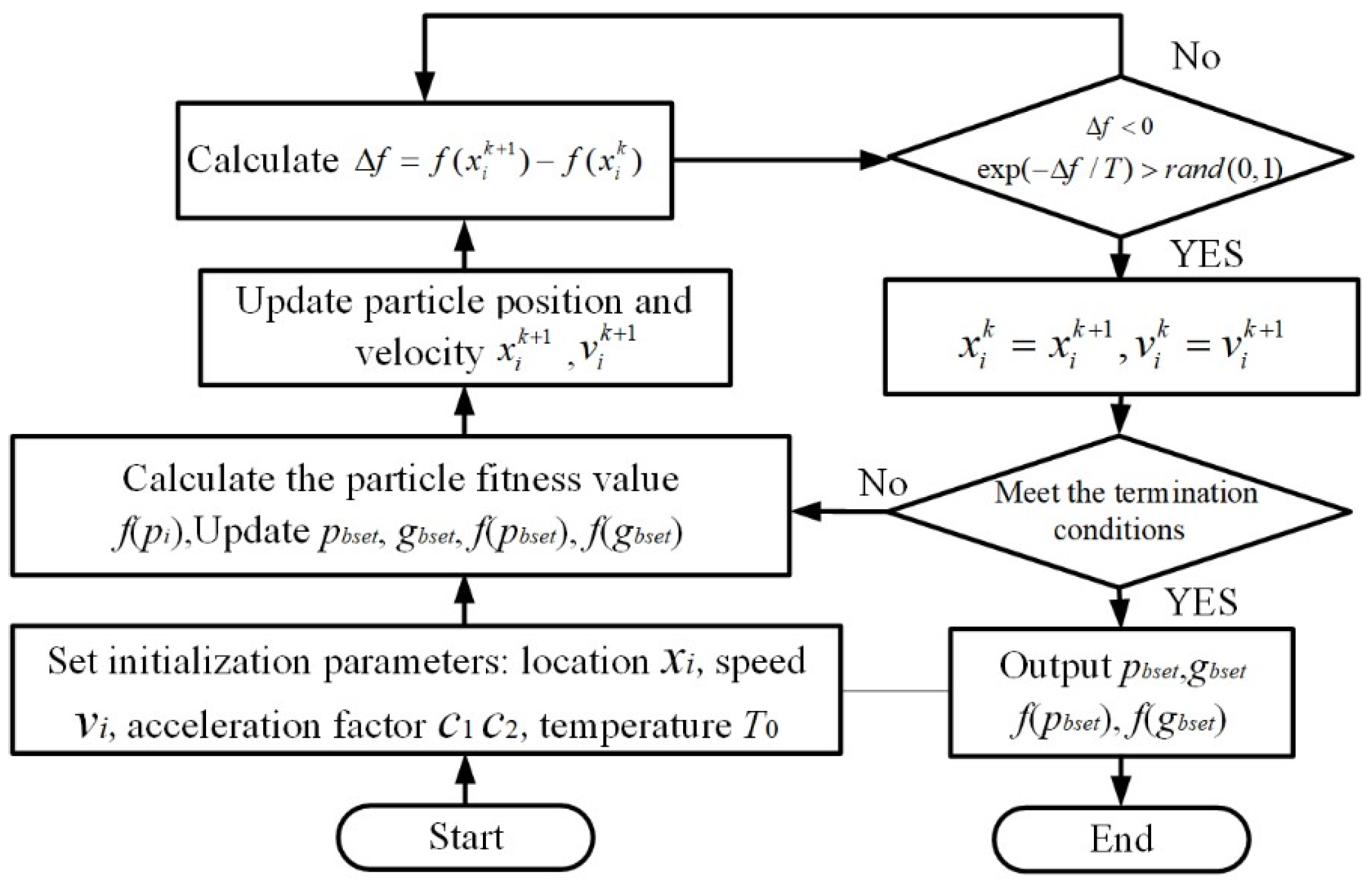
The core of the simulated annealing algorithm lies in the thermodynamic process of solid cooling. Annealing refers to the process where the energy of an object reaches its minimum value as the temperature decreases. The Metropolis criterion is the central criterion in the simulated annealing algorithm, characterized by accepting not only superior solutions during the temperature decrease process but also inferior solutions based on the probability distribution of the temperature variable. This increases the likelihood of the algorithm escaping local optima. Therefore, combining the Particle Swarm algorithm with the Simulated Annealing algorithm can effectively reduce the probability of the Particle Swarm algorithm becoming trapped in local optima.
The Simulated Annealing algorithm requires setting an initial temperature T based on the initial state of the population during the initial iteration stage. The temperature linearly decreases by a certain degree at each iteration, forming an optimization search process that encompasses searching for new solutions and gradual cooling. The Metropolis criterion is employed to ascertain whether a disturbance-generated new solution replaces the global optimal solution. The expression for the Metropolis criterion is as follows:
P = 1 f p n e w < f p o l d exp f p n e w f p o l d T f p n e w f p o l d .
Here, f(pold) represents the fitness value of the particle in its initial position state, f(pnew) represents the fitness value of the particle at its new position, and P denotes the acceptance probability for the system transitioning from the initial state to the new position state.
The initial temperature is determined based on the characteristics of the initial particle, and it subsequently decreases by a cooling factor α after each iteration. The temperature is decreased according to the following function:
T k + 1 = α T k , k = 0 , 1 , 2
When the temperature T is determined, the control algorithm establishes the conditions for the transition of particle state updates as follows:
(i)
If f(pold) < f(pnew), indicating a decrease in energy after the state change, the particle accepts pnew as its current state.
(ii)
If f(pold) < f(pnew), it denotes an increase in energy after the state change, indicating that the particle diverges from the optimal position. Subsequently, the control algorithm employs the rand (0, 1) function to generate a random number for comparison with the P value. If the P value is greater, the control algorithm accepts pnew as the current state. In contrast, if the P value is smaller, the current state remains as pold.
The principles and characteristics of the Simulated Annealing algorithm and the Particle Swarm algorithm were used to fuse the two algorithms. The flow of the resulting algorithm, called the Simulated Annealing Particle Swarm algorithm, is presented in Figure 8.
By following the algorithm principles and steps outlined above, a Simulated Annealed Particle Swarm Optimized PID initial force controller was developed in Matlab. The advantage of Matlab 2020 software lies in its concise and comprehensible programming syntax, as well as its extensive library of encapsulated functions and algorithms, enabling convenient and efficient scientific computations and engineering analyses. The controller was incorporated into Simulink using S-functions of Matlab, providing the foundation for performance simulations and experimental applications.

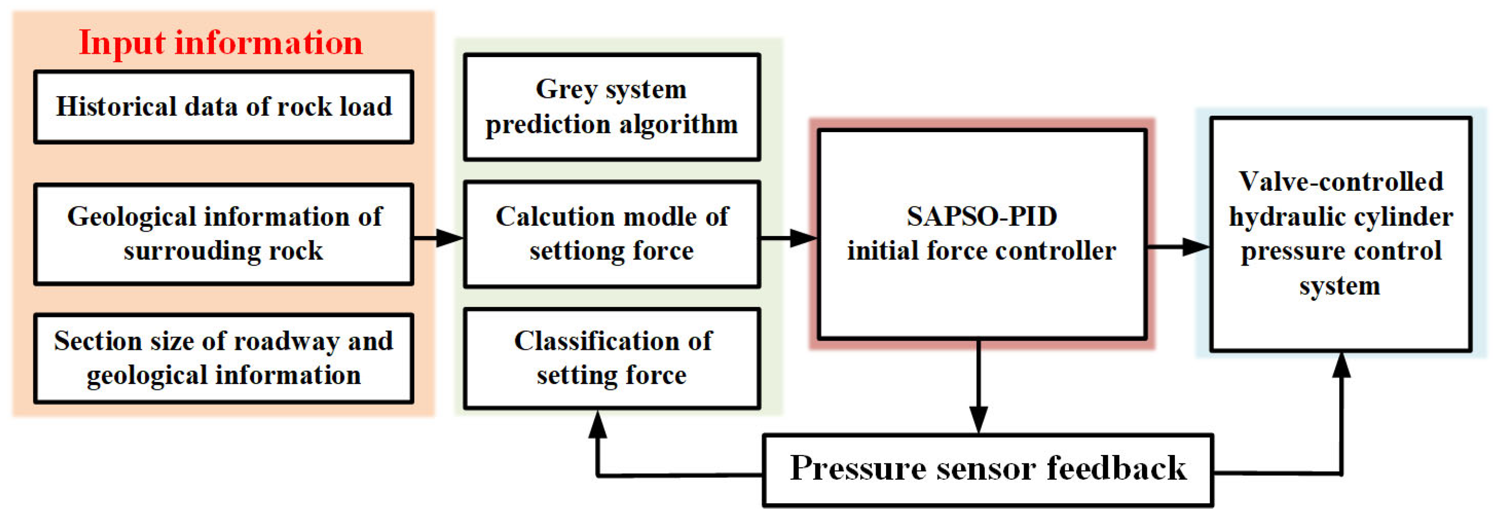
3.3. The Composition of the Initial Bracing Force Control System

The initial bracing force control system based on SAPSO-PID consists of an input module, an initial bracing force calculation, prediction, and classification module, a valve-controlled hydraulic cylinder pressure control system module, an SAPSO-PID initial bracing force controller module, and a pressure feedback module. The input module includes all the initial data. The composition structure of the initial force control system is depicted in Figure 9.

4. Simulation Model Building and Result Analysis of Initial Support Force Control System

To assess the effectiveness and advancement of the initial bracing force controller proposed in this paper, a simulation control system for the initial bracing force was set up on the server. This allowed for preliminary simulation experiments to be conducted prior to performing downhole experiments.

4.1. Modeling and Stability Verification of Temporary Support Hydraulic Control System

In the context of simulation analysis, the initial step involves mathematically modeling the hydraulic control system of the temporary support. This mathematical modeling allows for a comprehensive understanding and accurate representation of the system’s behavior during simulations.
During the process of mathematically modeling the hydraulic pressure control system of the temporary bracket, it is permissible to make appropriate assumptions considering the internal and external parameters, as well as the motion characteristics of the temporary bracket. Simultaneously, certain functional components can be excluded, while focusing on the comprehensive modeling of significant components. This approach enables effective simplification of the system’s complexity.
In the hydraulic cylinder pressure control system structure, the simulation primarily focuses on analyzing the dynamic relationship among the proportional relief valve, hydraulic cylinder, and load. As a result, functional components such as the hydraulic check valve and proportional directional valve can be omitted during the mathematical modeling process. Additionally, the hydraulic cylinder that supports the column is responsible for both raising the top plate support and lowering the unloading drop frame. However, hydraulic cylinder cavity pressure control is only required during the rising action to achieve initial bracing force control. Consequently, the modeling process disregards the lowering action of the bracket. In addition, the hydraulic cylinder pressure control system considers both internal and external parameters, as well as system characteristics. Firstly, the connection pipe is assumed to be short, neglecting the effects of pressure loss in the hydraulic pipeline, fluid mass effect, and pipeline dynamic characteristics. Secondly, temporary assumptions are made regarding the internal and external leakage of the hydraulic cylinder and each valve, viewing them as laminar flow. The fluid temperature is set to a constant value.
The following will combine the above conditions to analyze the mathematical model of the pilot proportional relief valve, hydraulic cylinder, and feedback sensor in the hydraulic cylinder pressure control system.

4.1.1. Establishment of the System Model

(1)
Pilot Operated Proportional Relief Valve Modeling
The pilot-operated proportional relief valve comprises a proportional amplifier, a proportional solenoid, an electromagnetic force, a pilot valve spool displacement conversion link, and a pilot valve spool displacement to output pressure conversion link.
The role of the proportional amplifier is to process, compute, and amplify the input voltage signal into a current signal, which is then used to control the proportional solenoid. In essence, the proportional amplifier can be described as a link that establishes proportionality.
K p a = I s U s ,
where Kpa is the gain coefficient of the proportional amplifier, A/V; I(s) is the current of the proportional amplifier, A; and U(s) is the input voltage of the proportional amplifier, V.
The proportional solenoid plays a crucial role in generating thrust on the armature, causing the movement of the pilot valve cone and consequent alteration in the magnitude of the pilot valve opening pressure. Due to its high frequency response, the proportional solenoid can be likened to a proportional link.
K p s = F s I s ,
where Kps is the current-force gain coefficient of the proportional electromagnet, N/A; F(s) is the corresponding output thrust of the electromagnet, N.
The mechanical balance equation of the pilot valve spool:
F P 4 A 4 = m s p d 2 x d t 2 + B s d x d t + K e s x + F s s 1 + F c f ,
where P4 is the outlet pressure of the pilot valve, N/m3; A4 is the effective area of the pilot valve spool, m2; P4A4 is the algebraic sum of the hydraulic pressure on the effective area, N; msp is the mass of the pilot valve spool, kg; x is the displacement of the spool, m; Bs is the equivalent damping factor of the valve, N/(m·s−1); Kes is the equivalent spring stiffness, N/m, which is the sum of the mechanical spring the sum of stiffness and steady-state hydrodynamic stiffness; Fss1 is the steady-state hydrodynamic force, N; and Fcf is the Coulomb friction force on the spool, N. Where P4A4, Fss1, and Fcf are usually negligible, the above equation is collated and the Laplace transformation is completed, the displacement of the pilot valve spool under the action of electromagnetic force can be obtained as:
x s = 1 m s p s 2 + B s s + K e s F s .
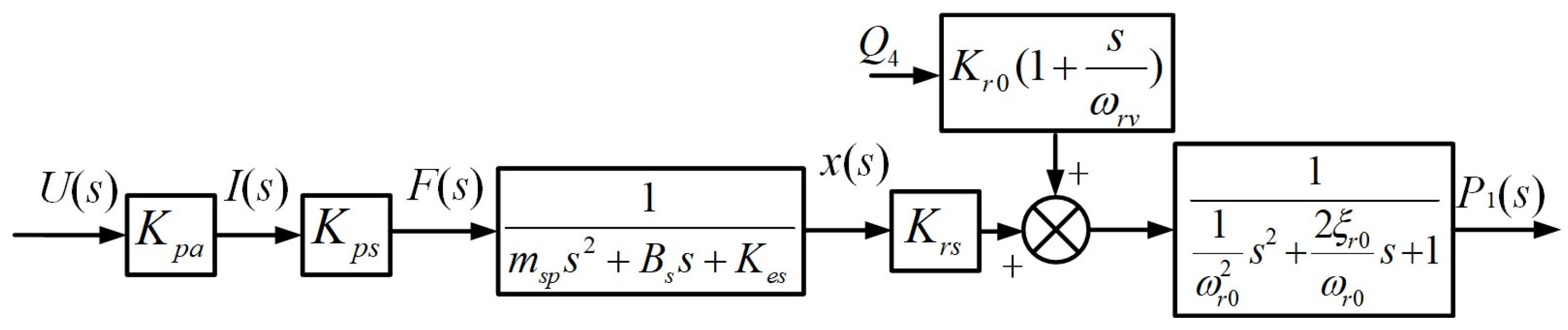
The output pressure of the main valve relies on both the displacement of the pilot valve spool and the flow rate within the lower volume chamber of the main valve. By analyzing the force equation and flow continuity equation of the main valve, and applying suitable simplifications, it is possible to derive the expression that establishes the relationship between the displacement of the pilot valve spool and the output pressure, as indicated by Equation (27). The specific process of derivation will not be depicted in this context.
P 1 = K r 0 1 + s ω r v Q 4 + K r s x 1 ω r 0 2 s 2 + 2 ξ r 0 ω r 0 s + 1 ,
where P1 is the pressure at the lower end of the main valve, N/m2; x is the displacement of the spool, m; Q4 is the flow rate of the lower volume chamber of the flow master valve, m3/s; ωrv is the turning frequency of the main valve spool movement, Hz; and Krs, Kr0, ξr0 and ωr0 are coefficients related to the intrinsic frequency of the main valve of the flow valve, the flow coefficient of each structure of the valve, and the frequency associated with the valve motion.
By organizing the transfer functions of the aforementioned links in series using Equations (23), (24), (26), and (27), the block diagram of the transfer function for the pilot-operated proportional relief valve is illustrated in Figure 10.
The expression for the output pressure of the pilot-operated proportional relief valve is as follows:
P 1 s = K p a K p s K r s m s p s 2 + B s s + K e s U s + K r 0 1 + s ω r s Q 4 1 1 ω r 0 2 s 2 + 2 ξ r 0 ω r 0 s + 1 .
(2)
Hydraulic Cylinder Modeling
Based on the motion characteristics of the hydraulic cylinder supporting the column, the mechanical equilibrium equation of the hydraulic cylinder can be derived as follows:
F H = A H P H = m p d 2 z d t 2 + B p d z d t + K m p z + F e f ,
where FH is the driving force generated by the hydraulic cylinder, N; AH is the effective pressure cross-sectional area of the hydraulic cylinder, m2; PH is the cavity pressure of the hydraulic cylinder, N/m2, because the relief valve is closer to the hydraulic cylinder, PH can be approximated as equal to P1; mp is the mass of the hydraulic cylinder plunger, kg; Bp is the equivalent damping factor of the hydraulic cylinder, N/(m·s−1); Kmp is the equivalent spring stiffness, N/m; z is the displacement of the hydraulic cylinder plunger, m; and Fef is the equivalent external load pressure, N, mainly including the gravity of the top beam of the support, etc.
Meanwhile, the flow equation of the hydraulic cylinder is:
Q H c = A H d z d t + C h c P H + V t 4 β e c d P H d t ,
where QHc is the hydraulic cylinder flow rate, m3/s; Chc is the internal leakage coefficient of the hydraulic cylinder, L/min/bar; Vt is the working volume cavity of the hydraulic cylinder, m3; and βec is the effective volume modulus of elasticity of the hydraulic cylinder, MPa.
Combining Equations (29) with (30) and performing the Laplace transformation, we obtain:
Q H c = A H 2 s m p s 2 + K m p + V t 4 β e c + C h c P H A H s m p s 2 + K m p F e f .
(3)
Pressure Feedback Sensor Modeling
Under normal conditions, the pressure sensor can be simplified as a proportional element, and its transfer function can be expressed as follows:
K f = U s A H P H s = U s F s ,
where Kf is the amplification factor of the pressure sensor, V/N.
By associating Equations (28), (31), and (32) and applying appropriate simplifications, we can derive the system transfer function relationship for controlling the hydraulic cylinder pressure using a relief valve. Figure 11 represents the relationship of the transfer function.

4.1.2. Control System Model Stability Analysis

To analyze the performance and validate the stability of the controlled object model within the system, the data for each system component was initially examined. Subsequently, the model parameters were selected considering the actual operating conditions. The stability analysis was conducted using the Nyquist criterion, while the system’s performance was evaluated through the Byrd diagram, unit step response, and unit impulse response. Table 3 presents the parameter values of the main components of a hydraulic cylinder system controlled by a specific model of safety valve. In practical applications, these parameter values may vary depending on the models of both the valve and the hydraulic cylinder.
From the relevant parameters listed in Table 3, the calculations yield the following values: ωr0 = 18.54 Hz, ωrv = 187.5 Hz, ωrA = 0.244 Hz, and ξr0 = 1.832. These parameters are then substituted into the transfer function shown in 
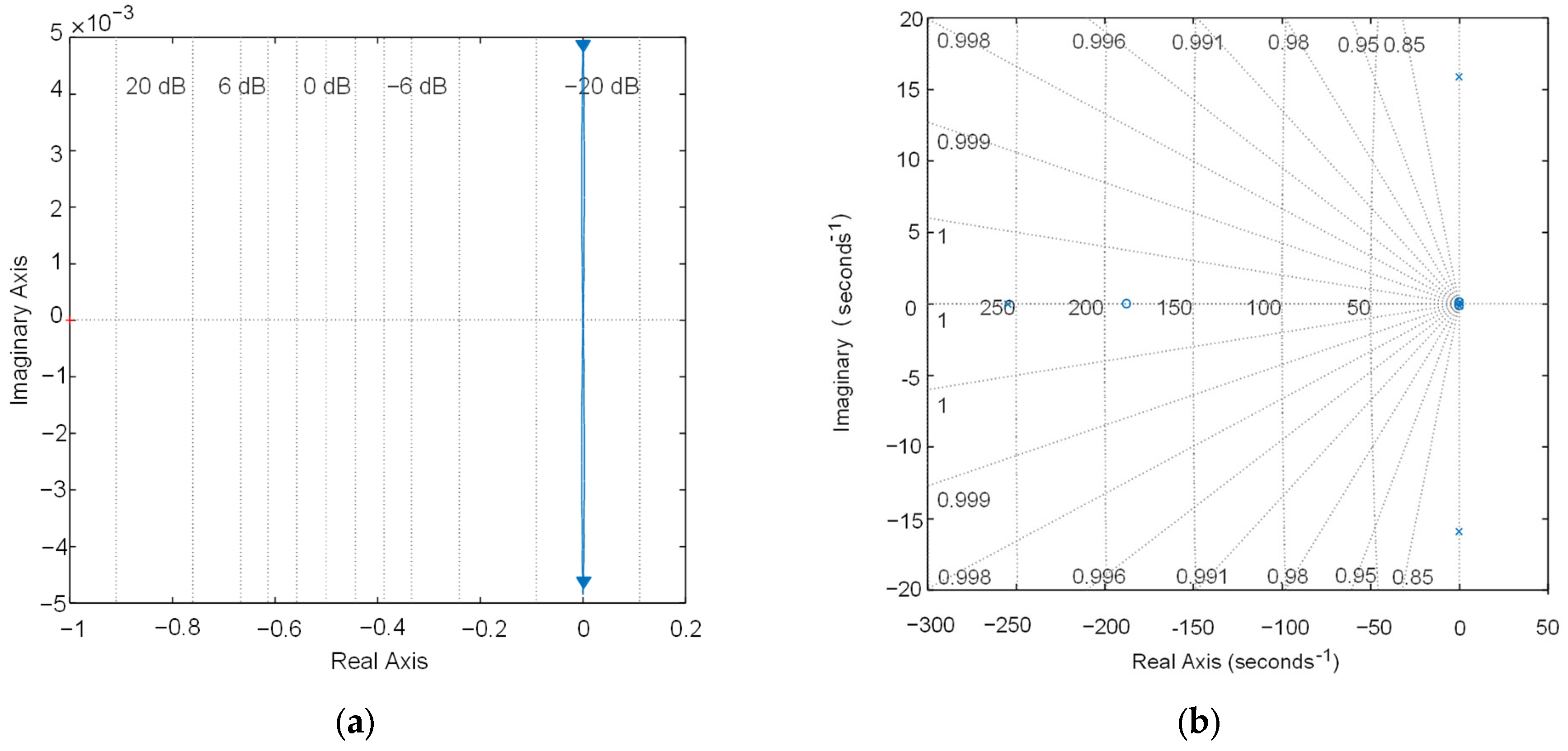
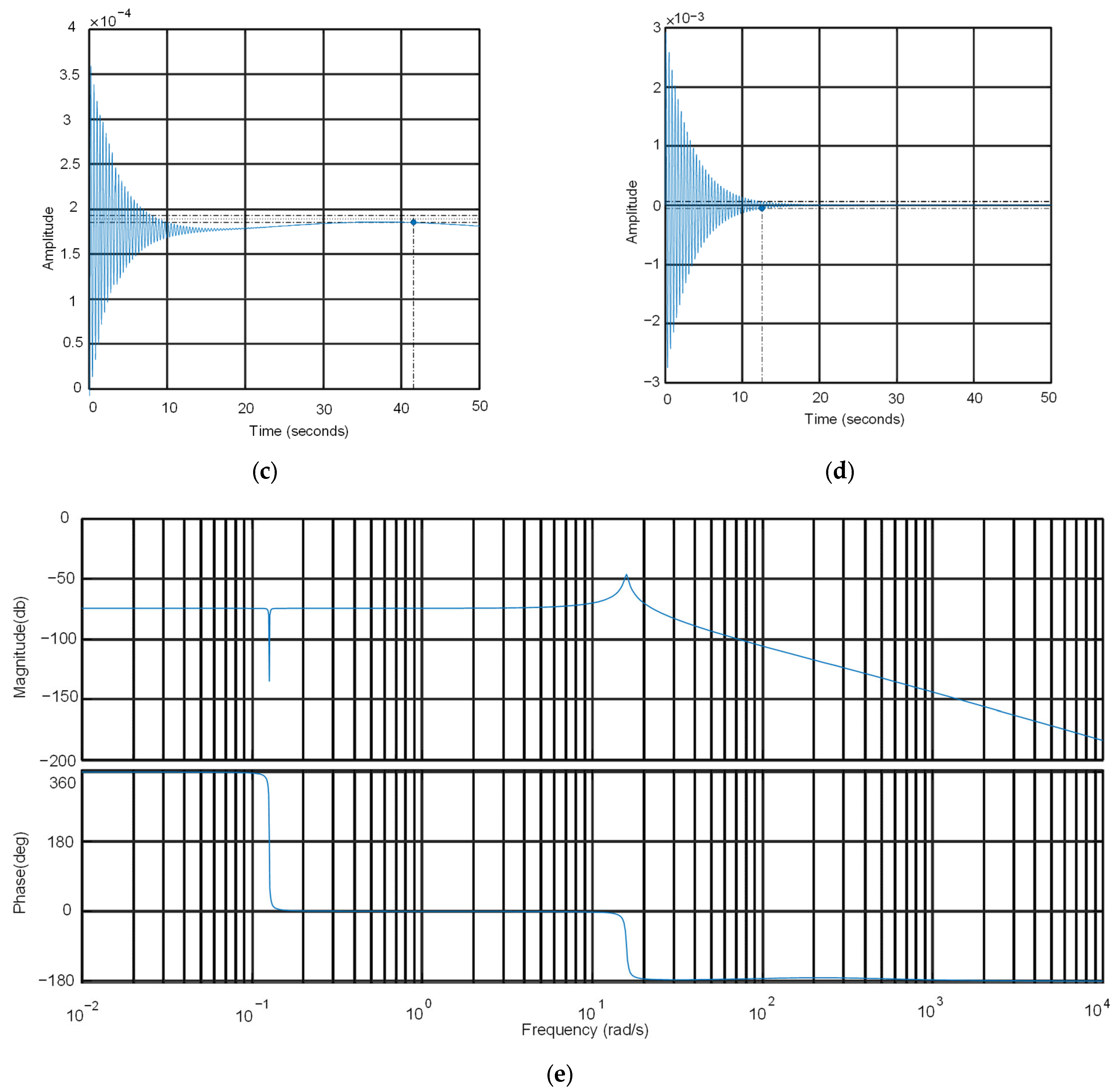
Figure 11. Utilizing the Matlab programming environment, the system’s Nyquist diagram, Bode diagram, pole-zero diagram, and unit step response and unit impulse response curves are plotted, as depicted in Figure 12.
It can be seen from Figure 12 that the number of turns around the point (−1, j0) in the Nyquist diagram of the open-loop system is 0, and the number of poles and zeros in the right half of the pole-zero diagram is 0. According to the Nyquist stability criterion, it can be seen that the pressure control closed-loop system of the overflow valve-controlled hydraulic cylinder is stable; in the Bode diagram of the system, it can be observed that the phase margin is greater than 40° and the amplitude margin is greater than 20 dB, indicating the stability of the system. It can be seen from the jump response graph that the system stabilizes after 41.6 s, and it can be seen from the impulse response curve that the system will return to a stable state after 12.6 s.
Hence, the hydraulic cylinder pressure control system model, presented in this study and governed by a temporary direct overflow valve, exhibits stability. Additionally, it is evident that the inherent response speed and sensitivity of the hydraulic cylinder control system are sluggish and inadequate. To enhance both the response speed and sensitivity, an SAPSO-PID initial bracing force controller was introduced into the control system during simulation.

4.2. Simulation Model Building

To ensure a more realistic simulation, the control system for the simulation was constructed using the integrated simulation platform of AMESim and Matlab/Simulink [22,
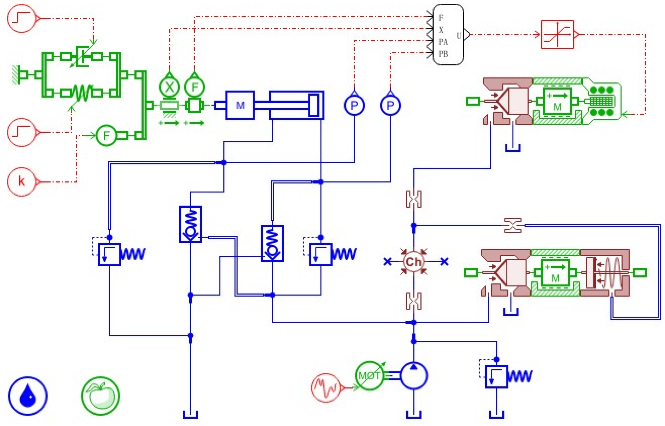
23]. The AMEsim 2020 software enables multi-domain system modeling and simulation, supporting the simulation of diverse systems encompassing mechanical, hydraulic, and control domains. It aids engineers in conducting system-level modeling, simulation analysis, and performance evaluation, contributing to the optimization of system design. The pressure system of the valve-controlled hydraulic cylinder was then modeled in AMESim, utilizing the mathematical model established in the preceding section. Figure 13 illustrates the depicted model.
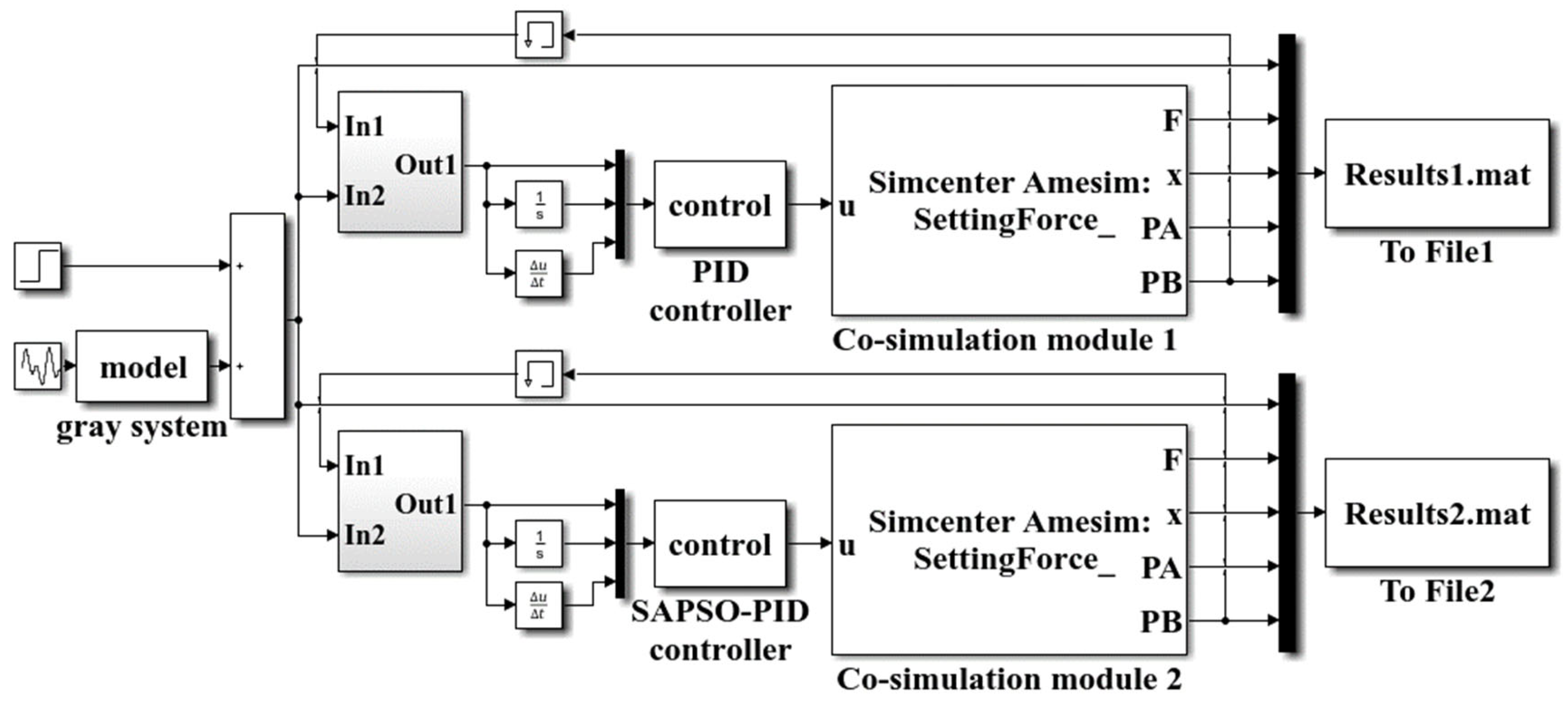
The gray system, PID controller, and SAPSO-PID controller are implemented in Matlab/Simulink using programming techniques. Instead of the roadway roof load, the elastic load and damping load are applied, with a stiffness coefficient of 10,000 N/mm and a damping coefficient of 10 N·s/m. Based on the previous mathematical model, the gray system calculates and predicts the initial bracing force, which is set as the input signal of the simulation control system to achieve different levels of initial bracing force [30,31]. The joint simulation model of AMESim and Matlab/Simulink is illustrated in Figure 14.

4.3. Analysis of Simulation Results

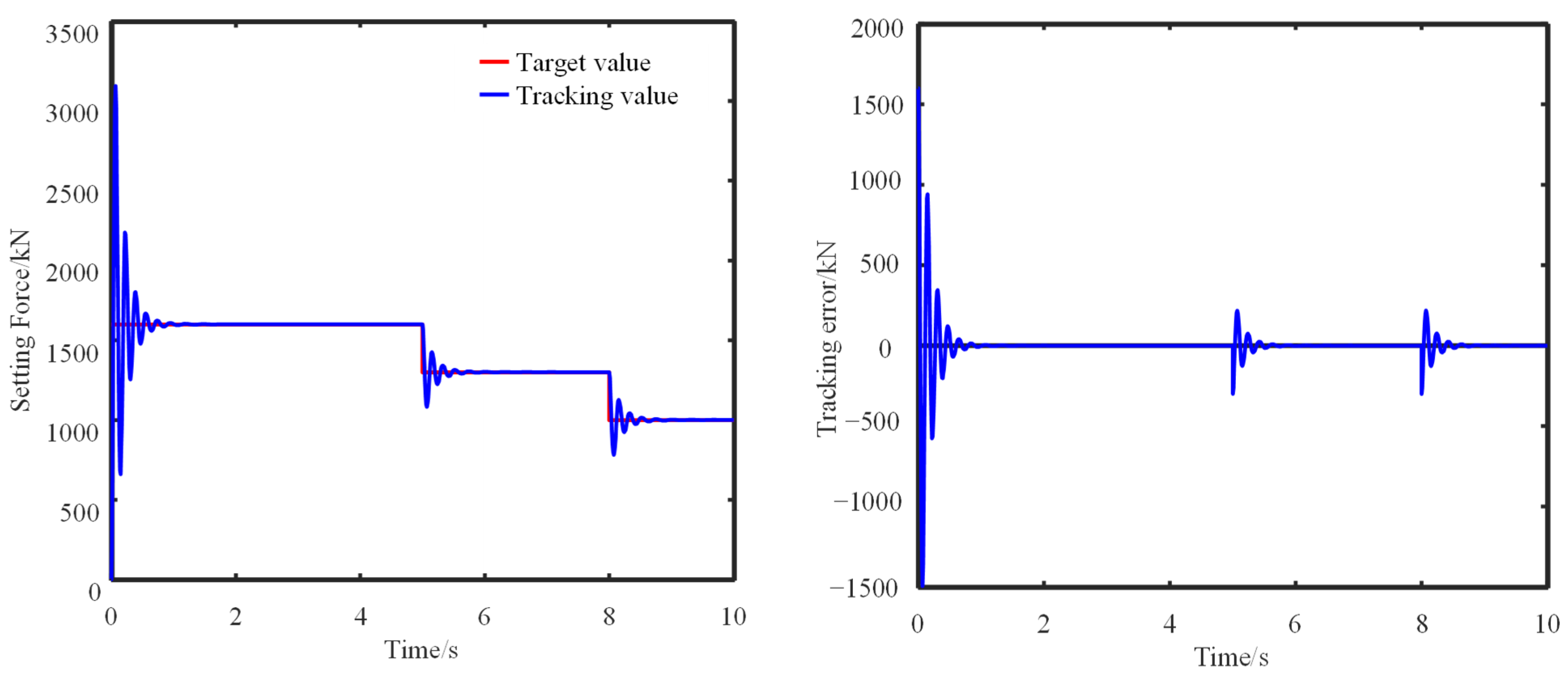
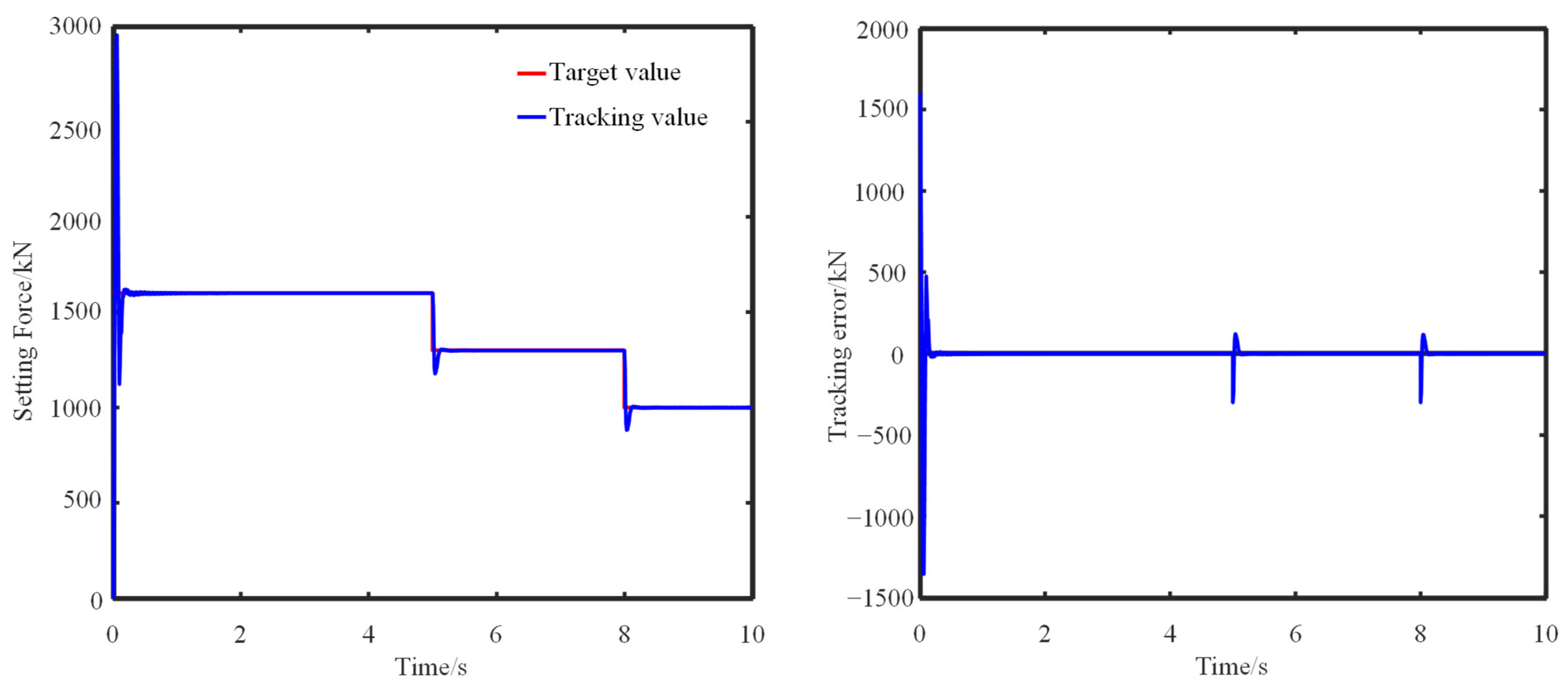
The predicted initial bracing force levels from the gray prediction system for various time periods were utilized as input signals for the controller. Figure 15 and Figure 16 exhibit the dynamic response and error curves of the hydraulic cylinder’s initial bracing force control using both the PID controller and SAPSO-PID controller. In comparison to the PID controller, the SAPSO-PID initial force controller showcases improved response time by 85.6%, 81.4%, and 81.6% across the three initial bracing force levels, as well as reduced overshoot by 9.31%, 47.3%, and 46.7%, respectively. Moreover, the SAPSO-PID controller exhibits a superior tracking response performance with smooth amplitudes and minimal excitation, thus mitigating the chattering phenomenon caused by excessive input switching.
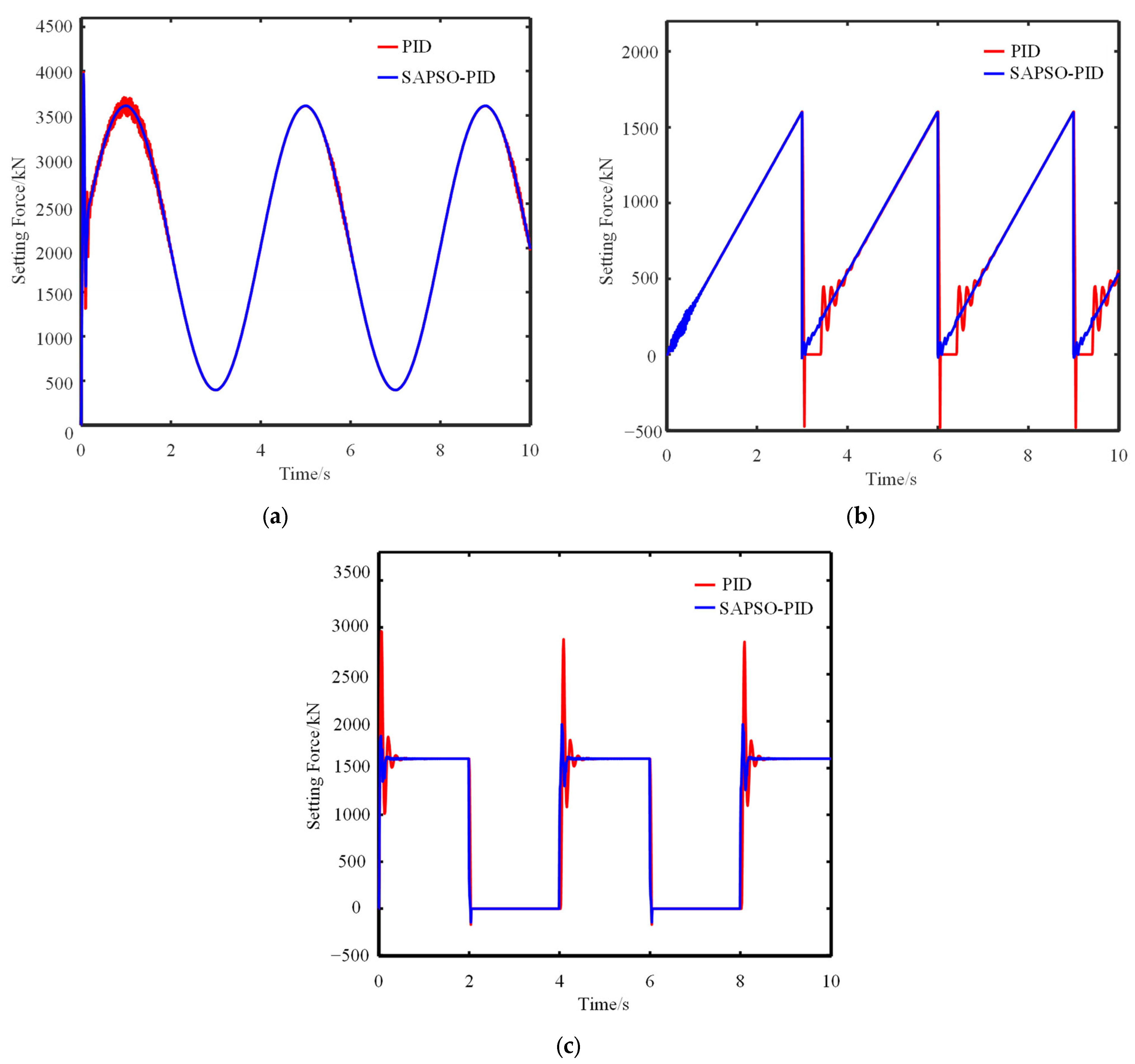
To further validate the dynamic response of the SAPSO-PID initial force controller in response to periodic signals, the system was subjected to periodic sine, sawtooth, and square wave input signals. The resulting dynamic response curves are presented in Figure 17.
In Figure 17a, when a sinusoidal signal was applied, the SAPSO-PID controller exhibited a reduction in system response time by 90.9% and a decrease in overshoot by 25.8% when compared to the conventional PID controller. In Figure 17b, when a sawtooth wave signal is used as input, the SAPSO-PID control algorithm achieves a remarkable reduction in system response time by 86.3% and an 87.3% decrease in overshoot, without accounting for the coarse error resulting from system delay. Similarly, in Figure 17c, the SAPSO-PID control algorithm exhibits a 60.98% reduction in the system’s response time and an 82.1% decrease in overshoot when a square wave signal is applied. These simulation results highlight the superior dynamic performance of the SAPSO-PID controller proposed in this study, particularly when operating under various working period signals. Please refer to Table 4 for specific simulation data.

5. Experiment

5.1. Experimental Protocol

To validate the efficacy of the proposed temporary support initial bracing force controller, an experimental system was constructed in the excavation tunnel of Qianjuntai coal mine, which is under the administration of China Jingmei Group. Figure 18 displays the configuration of the experimental system. The temporary brace, as proposed by the researchers, was substituted with a joint temporary brace designed with a similar structure. The intelligent emulsion pumping station was employed as the power source for brace support. The intelligent emulsion pumping station is a vital equipment component within the hydraulic support system, primarily intended for emulsion supply to the hydraulic support. Emulsion, created by blending water and emulsifiers, functions in the hydraulic support system by providing lubrication, cooling, sealing, and corrosion prevention. The emulsion pump generates adequate pressure to transport the emulsion within the hydraulic support system. The pipeline system and valves regulate the flow and distribution of the emulsion, thus ensuring optimal support force and posture. In contrast to conventional manually adjusted emulsion pumping stations, the control system implemented in this study enables automated monitoring and adjustment of the pumping station’s operational status, responding to changes in roof support pressure.
Within the control box of the intelligent emulsion pumping station, the programmable controller utilizes the Controller Area Network (CAN) bus to establish communication protocol with the host computer and collection board. This allows for automated control of the valve port. The manipulation of the oil pipe’s output pressure, which is connected to the temporary support, facilitates regulation of the pressure in the lower chamber of the hydraulic cylinder of the column. As a result, the initial support force of the temporary support can be precisely adjusted.
The B&R Automation Studio 4.7 software was utilized for configuring, programming, monitoring, and diagnosing the temporary support initial bracing force control algorithm and parameters [32]. An analog signal, representing the range of initial bracing levels calculated based on geological conditions for each group of temporary supports, is input to the host computer to simulate the actual bracing requirements.

5.2. Experimental Results

Throughout the experiment, the pressure sensor measured the pressure in the lower chamber of the hydraulic cylinder of each group of temporary support columns, which can be considered an indication of the initial bracing force magnitude. Three groups were established with varying levels of initial bracing force. These levels were input to the host computer, which facilitated the adjustment and monitoring of the initial bracing force. The experimental findings are displayed in Figure 19.
Based on the experimental results, the SAPSO-PID initial bracing force controller demonstrated an improved average rise time compared to the conventional PID control across different initial bracing force levels. The SAPSO-PID controller achieved a reduction of 5.85%, 45.73%, and 14.83% in average rise time for the three different force levels, respectively. Moreover, the SAPSO-PID controller showcased significant improvements in system error fluctuation compared to the conventional PID control, exhibiting a reduction of 91.50%, 40.75%, and 71.97% in pressure error, respectively. These findings highlight the efficacy of the pressure feedback-based initial bracing force control system proposed in this paper, emphasizing its ability to achieve efficient adaptive control of the initial bracing force.

6. Conclusions

(1)
Developed a temporary support design for underground coal mine excavation tunnels and investigated the roof control mechanism of the support system. Created calculation and prediction models for the initial bracing force levels of the temporary support in the excavation tunnels, enabling accurate forecasting of bracing force requirements at different locations within the tunnels.
(2)
Designed an initial bracing force controller based on the SAPSO-PID approach and established a control system model specifically for the initial bracing force. Constructed a mathematical model to represent the pressure system of the pilot-operated relief valve-controlled hydraulic cylinder and subjected it to analysis and stability verification.
(3)
An integrated simulation platform combining AMESim and Matlab was employed to develop a simulation model for the initial bracing force control system utilizing the SAPSO-PID methodology. The simulation results demonstrate the outstanding performance of the SAPSO-PID initial bracing force control system in terms of response time and error control, highlighting its effectiveness in achieving efficient and adaptive control of the initial bracing force.
(4)
Carried out experiments within underground coal mine excavation tunnels where structurally similar temporary support systems based on the SAPSO-PID initial bracing force control were employed. The experimental findings demonstrate that the implemented bracing force control system effectively and adaptively manages the initial bracing force of the temporary support structures in the excavation tunnels. The temporary bracing control system utilized in the experiment demonstrates its universal applicability in coal mine excavation tunnels. It enables the adjustment of temporary bracing dimensions based on the tunnel cross-section dimensions in different projects while preserving the effectiveness of the control system remains intact.
The research presented in this paper contributes to the advancement of intelligent construction methods in the field of underground mining and the development of unmanned coal mining equipment technologies within the coal mining industry.

Author Contributions

Conceptualization, D.W. and R.L.; methodology, J.C. and D.W.; software, W.Z.; validation, Y.S., D.W. and M.W.; formal analysis, S.Z.; investigation, S.Z.; resources, M.W.; data curation, R.L.; writing—original draft preparation, D.W.; writing—review and editing, R.L.; visualization, W.Z.; supervision, M.W.; project administration, S.Z.; funding acquisition, M.W. All authors have read and agreed to the published version of the manuscript.

Funding

This research was funded by Theory and Method of Excavation-Support-Anchor Parallel Control for Intelligent Excavation Complex System, grant number 52104169 and China Postdoctoral Science Foundation, grant number 2023M731944. This research was supported by Youth Found of the National Natural Science Foundation of China grant number 52104169 and China Postdoctoral Science Foundation, grant number 2023M731944.

Data Availability Statement

The data used to support the findings of this study are included within the article.

Conflicts of Interest

The authors declare that they have no conflict of interest.

References

  1. Beeche, C.A.; Garcia, M.A.; Leng, S.; Roghanchi, P.; Pu, J. Computational risk modeling of underground coal mines based on NIOSH employment demographics. Saf. Sci. 2023, 164, 106170. [Google Scholar] [CrossRef] [PubMed]
  2. Bosikov, I.I.; Martyushev, N.V.; Klyuev, R.V.; Savchenko, I.A.; Kukartsev, V.V.; Kukartsev, V.A.; Tynchenko, Y.A. Modeling and Complex Analysis of the Topology Parameters of Ventilation Networks When Ensuring Fire Safety While Developing Coal and Gas Deposits. Fire 2023, 6, 95. [Google Scholar] [CrossRef]
  3. Malozyomov, B.V.; Golik, V.I.; Brigida, V.; Kukartsev, V.V.; Tynchenko, Y.A.; Boyko, A.A.; Tynchenko, S.V. Substantiation of Drilling Parameters for Undermined Drainage Boreholes for Increasing Methane Production from Unconventional Coal-Gas Collectors. Energies 2023, 16, 4276. [Google Scholar] [CrossRef]
  4. IEA (International Energy Agency). Coal 2019 Analysis and Forecasts to 2024; IEA: Paris, France, 2019. [Google Scholar]
  5. Bian, W.; Chen, T.; Chen, X.; Ge, C.; Hui, Z.; Yang, H. Study and enlightenment of energy policies of major developed countries. Bull. Chin. Acad. Sci. 2019, 34, 488–496. [Google Scholar]
  6. Shen, Y.; Wang, P.; Zheng, W.; Ji, X.; Jiang, H.; Wu, M. Error Compensation of Strapdown Inertial Navigation System for the Boom-Type Roadheader under Complex Vibration. Axioms 2021, 10, 224. [Google Scholar] [CrossRef]
  7. Cai, L.; Meng, F.L.; Li, S.C.; Guo, W.Y. Temporary Support Technology of Roadheader. Coal Mine Mach. 2013, 34, 189–191. [Google Scholar]
  8. Ma, H.; Wang, S.; Mao, Q. Key common technology of intelligent heading in coal mine roadway. J. China Coal Soc. 2021, 46, 310–320. [Google Scholar]
  9. Li, R.; Jiang, W.; Wang, P.; Cheng, J.; Wu, M. Asynchronous coupling approach for leveling control of self-shifting temporary support. J. China Coal Soc. 2020, 45, 3625–3635. [Google Scholar]
  10. Li, R. Research on the Key Technology of Self-Moving Over-Supporting in Integrated Roadway Excavation. Ph.D. Thesis, Mechanical Electronic and Information Engineering, China University of Mining & Technology (Beijing), Beijing, China, 2021. [Google Scholar]
  11. Wang, G.; Niu, Y. Study on advance hydraulic powered support and surrounding rock coupling support system and suitability. Coal Sci. Technol. 2016, 44, 19–25. [Google Scholar] [CrossRef]
  12. Lu, J.N. Research on the Mechanical Characteristics of Step Ahead Support System for Integrated Roadway Excavation. Ph.D. Thesis, Liaoning University of Engineering and Technology, Fuxin, China, 2015. [Google Scholar]
  13. Liu, Y.Z. Research on the Structure and Performance of the Self-Propelled Support Equipment Accompanying Road Header of Comprehensive Roadway. Master’s Thesis, Liaoning Technical University, Fuxin, China, 2019. [Google Scholar]
  14. Ding, S.; Bai, J.; Han, J.; Wang, H.; Ma, F. Mechanical Characteristics Analysis and Structural Optimization of Key Component of Self-Moving Temporary Support. Appl. Sci. 2022, 12, 10745. [Google Scholar] [CrossRef]
  15. Ma, H.; Wang, J.; Wang, C.; Zhang, H.; Xue, X.; Liu, P.; Tian, H. Lightweight design of temporary support device of rectangular shield for the robot system of coal mine roadway excavation. Adv. Mech. Eng. 2023, 15, 16878132231180791. [Google Scholar] [CrossRef]
  16. Xue, G.; Cheng, J.; Guan, J.; Chai, J.; Zhang, G.; Hao, X.; Wu, M. The method for determining working resistance of advance support bracket in deep fully mechanized roadway based on Flac3D. Adv. Mech. Eng. 2018, 10, 1687814018783624. [Google Scholar] [CrossRef]
  17. Xue, G.; Guan, J.; Chai, J.; Zhang, H.; Qu, Y. Adaptive control of advance bracket support force in fully mechanized roadway based on neural network PID. J. China Coal Soc. 2019, 44, 3596–3603. [Google Scholar]
  18. Cheng, J.; Wan, Z.; Peng, S.; Zhang, H.; Xing, K.; Yan, W.; Liu, S. Technology of intelligent sensing of longwall shield supports status and roof strata based on massive shield pressure monitoring data. J. China Coal Soc. 2020, 45, 2090–2103. [Google Scholar]
  19. Ding, K.; Wang, L.; Tian, J.; Ren, B.; Jiang, C.; Wang, S. Design of a Highly Adaptable Advance Support for a Deep, Fully Mechanized Roadway and Analysis of Its Support Performance. Appl. Sci. 2022, 12, 12728. [Google Scholar] [CrossRef]
  20. Zhao, T.; Liu, C.; Yetilmezsoy, K.; Gong, P.; Chen, D.; Yi, K. Segmental adjustment of hydraulic support setting load in hard and thick coal wall weakening: A study of numerical simulation and field measurement. J. Geophys. Eng. 2018, 15, 2481–2491. [Google Scholar] [CrossRef]
  21. Chen, H.; Zhang, K.; Sun, Z.; Hu, C.; Li, Y.; Wei, X.; Du, M.; Liu, Y.; Wang, X. Construction and experimental verification of the spatial attitude kinematic model of advanced support equipment. Sci. Rep. 2022, 12, 17959. [Google Scholar] [CrossRef]
  22. David, B.; David, A. MATLAB Handbook with Applications to Mathematics, Science, Engineering, and Finance; Chapman & Hall/CRC: Boca Raton, FL, USA, 2019. [Google Scholar]
  23. Liang, Q.; Xie, J.; Nie, L. Amesim Mechatronics Simulation Tutorial (Chinese Edition); Machinery Industry Press: Beijing, China, 2021. [Google Scholar]
  24. Liu, S.; Tao, L.; Xie, N.; Yang, Y. On the new model system and framework of grey system theory. In Proceedings of the 2015 IEEE International Conference on Grey Systems and Intelligent Services (GSIS), Leicester, UK, 18–20 August 2015; pp. 1–11. [Google Scholar]
  25. Wai, R.; Lee, J.; Chuang, K. Real-time PID control strategy for maglev transportation system via particle swarm optimization. IEEE Trans. Ind. Electron. 2010, 58, 629–646. [Google Scholar] [CrossRef]
  26. Liu, Y.; Jiang, D.; Yun, J.; Sun, Y.; Li, C.; Jiang, G.; Kong, Y.; Tao, B.; Fang, Z. Self-tuning control of manipulator positioning based on fuzzy PID and PSO algorithm. Front. Bioeng. Biotechnol. 2022, 9, 1443. [Google Scholar] [CrossRef]
  27. Harrison, K.; Engelbrecht, A.; Ombuki-Berman, B. Self-adaptive particle swarm optimization: A review and analysis of convergence. Swarm Intell. 2018, 12, 187–226. [Google Scholar] [CrossRef]
  28. Geng, J.; Li, M.; Dong, Z.; Liao, Y. Port throughput forecasting by MARS-RSVR with chaotic simulated annealing particle swarm optimization algorithm. Neurocomputing 2015, 147, 239–250. [Google Scholar] [CrossRef]
  29. Saffaran, A.; Moghaddam, M.A.; Kolahan, F. Optimization of backpropagation neural network-based models in EDM process using particle swarm optimization and simulated annealing algorithms. J. Braz. Soc. Mech. Sci. Eng. 2020, 42, 1287–1300. [Google Scholar] [CrossRef]
  30. Lin, T.; Wang, Q.; Hu, B.; Gong, W. Research on the energy regeneration systems for hybrid hydraulic excavators. Autom. Constr. 2010, 19(8), 1016–1026. [Google Scholar] [CrossRef]
  31. Zeng, X.; Li, G.; Yin, G.; Song, D.; Li, S.; Yang, N. Model predictive control-based dynamic coordinate strategy for hydraulic hub-motor auxiliary system of a heavy commercial vehicle. Mech. Syst. Signal Process. 2018, 101, 97–120. [Google Scholar] [CrossRef]
  32. Herbuś, K.; Ociepka, P. Verification of operation of the actuator control system using the integration the B&R Automation Studio software with a virtual model of the actuator system. In IOP Conference Series: Materials Science and Engineering; IOP Publishing: Bristol, UK, 2017; Volume 227, p. 012056. [Google Scholar]
Figure 1. Excavation support distributed process flow.
Axioms 12 00948 g001
Figure 2. Excavating and supporting anchor complete sets of equipment and a new parallel process.
Axioms 12 00948 g002
Figure 3. Schematic diagram of temporary support structure for underground roadway excavation. 1—The top beam, 2—moving cylinder, 3—balance jack, 4—base, 5—Horizontal telescopic beam, 6—Column hydraulic cylinder, 7—Guard board.
Axioms 12 00948 g003
Figure 4. Model for calculating the initial bracing force of the support at the excavation working face.
Axioms 12 00948 g004
Figure 5. Schematic diagram of the initial support force range based on the pressure in the hydraulic cylinder chamber.
Axioms 12 00948 g005
Figure 6. The affiliation function of fuzzy controller F1.
Axioms 12 00948 g006
Figure 7. Hierarchical of the output of the initial support level.
Axioms 12 00948 g007
Figure 8. Flow chart of Simulated Annealing Optimized Particle Swarm algorithm.
Axioms 12 00948 g008
Figure 9. The composition structure of the initial support force control system based on SAPSO-PID.
Axioms 12 00948 g009
Figure 10. Pilot-operated proportional relief valve transfer function block diagram.
Axioms 12 00948 g010
Figure 11. Block diagram of relief valve-controlled hydraulic cylinder pressure system transfer function.
Axioms 12 00948 g011
Figure 12. Control system performance curves and step response and impulse curves. (a) Nyquist diagram; (b) Pole-zero diagram; (c) Step response; (d) Impulse response;(e) Bode diagram.
Axioms 12 00948 g012aAxioms 12 00948 g012b
Figure 13. AMESim-based model of relief valve-controlled hydraulic cylinder.
Axioms 12 00948 g013
Figure 14. Joint simulation model based on AMESim and Matlab/Simulink.
Axioms 12 00948 g014
Figure 15. Target tracking and error variation curve of PID controller.
Axioms 12 00948 g015
Figure 16. Target tracking and error variation curve of SAPSO-PID controller.
Axioms 12 00948 g016
Figure 17. Different signal input response. (a) Sine wave signal input response; (b) Sine wave signal input response; (c) Square wave signal input response.
Axioms 12 00948 g017
Figure 18. Schematic diagram of the composition of the experimental system.
Axioms 12 00948 g018
Figure 19. Pressure dynamic response curves for different initial bracing force levels. (a) Pressure dynamic response process at higher initial support level; (b) Pressure dynamic response curve at medium level of initial bracing force; (c) Pressure dynamic response curve at medium level of initial bracing force.
Axioms 12 00948 g019
Table 1. Hydraulic cylinder chamber pressure as a function of the bracing force.
P0/(kN)800110013001600
Pt/(MPa·s)537386110
Table 2. Running results of gray system prediction model.
NumberActual DataForecast DataResidualRelative Error
160.560.3710.1290.213%
260.160.28370.1840.306%
36060.0420.0420.070%
459.859.7454−0.0550.092%
559.959.3813−0.5190.866%
658.558.93440.4340.741%
758.458.3859−0.0140.024%
Table 3. The relief valve control hydraulic cylinder pressure system parameters to take the value of the table.
ParametersUnitValue
KpaA/V25
KpsN/A6.2
KesN/m2910
mspkg0.002
A4mm219.625
KssN/m12,000
ωrvHz3.4
AHmm24.3
mpkg250
BpN/(m·s1)300
KmpN/m3.2 × 106
Table 4. Summary of simulation results.
Algorithm Input Signal Overshoot (kN)Response Time (s)
PIDsignal level10.9341.04
20.1670.59
30.1990.49
Sine wave0.5971.98
Sawtooth0.3144.02
Square0.8480.41
SAPSO-PIDsignal level10.8470.15
20.0880.11
30.1060.09
Sine wave0.4430.18
Sawtooth0.0400.55
Square0.1520.16
Disclaimer/Publisher’s Note: The statements, opinions and data contained in all publications are solely those of the individual author(s) and contributor(s) and not of MDPI and/or the editor(s). MDPI and/or the editor(s) disclaim responsibility for any injury to people or property resulting from any ideas, methods, instructions or products referred to in the content.

