Enhancement of Deep Drilling for Stainless Steels by Nano-Lubricant through Twist Drill Bits


1
Faculty of International Training, Thai Nguyen University of Technology, Thai Nguyen 25000, Vietnam
2
Thai Nguyen School for Gifted Students, Thai Nguyen 25000, Vietnam
*
Author to whom correspondence should be addressed.
Lubricants 2022, 10(8), 173; https://0-doi-org.brum.beds.ac.uk/10.3390/lubricants10080173
Submission received: 6 June 2022
/
Revised: 26 June 2022
/
Accepted: 27 June 2022
/
Published: 29 July 2022
(This article belongs to the Special Issue Cooling/Lubrication Methods in Surface Engineering and Machining Applications of Different Materials)
Abstract
:This paper represents a new lubricant method which is able to one-stroke drill deep holes with a length-to-diameter of 8, on the AISI SUS 304 stainless steel. By adding graphene nanosheet into typical soluble emulsion and then mixing with water, a nano fluid can be made. The results revealed that using nanofluid can provide a reduction of 4.4-fold of the drilling torque, and thus expand the tool life as many as 20 times, compared with using typical emulsion lubricant. The proper set of cutting parameters was found by using Taguchi L9 experiments as 550 rpm spindle speed and 0.05 mm/rev. The results can be expanded to apply in other deep drilling of hard-to-cut material, using inexpensive devices and avoiding peck-drilling. The proposed lubricant can also be promissing for other machining operations.
1. Introduction
Nowadays, stainless steels have become more popular and a part of everyone’s life, and they have widespread applications in all kinds of industries [1], especially in aeronautical, automotive, chemical, and food processing [2,3]. Stainless steels have abundant outstanding characteristics, such as easy cleaning, good corrosion resistance, long durability, high strength, high corrosion, stainless, low maintenance, and luster. However, stainless steels are also considered one of the most difficult to cut compared to other grades due to their high work hardening tendency, low thermal conductivity, and high ductility. For example, the thermal conductivity of stainless steels is around 15 W/mK, one-third of plain carbon steel (45 W/mK) and more than 15 times lower than aluminum (235 W/mK), would cause a quick degradation of the cutting tools [4,5]. Drilling stainless steels is considered as a challenging process due to its strain hardening, high plasticity, toughness, tendency to form build-up edges, and difficulty in chip evacuation [3,4,6]. The induced chips must flow out through the drill flutes. In deep drilling, i.e., where the ratio between the drilling depth, L, and the hole diameter, D is larger than five [7,8], the removal of chips is slower than the amount of chips induced. The reason for this is that a high friction is induced among the chip, the tool flutes, and the hole wall, resulting in chip clogging, increases of torque and thrust force, and tool failure [7,9]. Consequently, providing proper lubricant to reduce both the cutting heat and the friction between chips and the drill flutes has been the most important issue in drilling of hard-to-cut materials, especially for stainless steels. Abundant investigations have been made to address this concern, such as applying cryogenic cooling [6,10], using surface-treated and coated tools [2], and optimizing the cutting geometry of the drill bits [4].
To enhance the production rate and expand the tool life in metal machining, especially for hard-to-cut materials, cutting fluids in flooded form have been the conventional choice for lubrication, cooling, and chip evacuation. However, there have been a number of drawbacks with the use of flooded cutting fluids, such as the total manufacturing cost, the difficulty of providing the fluid into the cutting area, productivity, and the serious health risk to operators. The greatest difficulty concerning deep drilling is that it cannot supply the lubricant or coolant into the cutting zone. When drilling holes with aspect ratios larger than three, external cooling is considered as near dry drilling processes [11], because the coolant does not sufficiently reach to the drill tip at the cutting zone due to the counter flow of the chips [7]. Hence, internal coolant supplying is an alternative choice for large aspect ratio drillings. Nevertheless, the coolant must be applied with pressure as high as 60 bars to be effective [12].
Another approach has been proposed to enhance the cutting ability in drilling by using minimum quantity lubricant (MQL). However, applying MQL with internal coolant holes on drill bits for deep drilling requires high air pressure; for example, a minimum of four bars for holes with L/D less than five, five to six bars for holes with L/D up to fifteen, and six to eight bars for holes with L/D greater than fifteen [13]. In deep drilling of AISI 4144 M (with a thermal conductivity of 42.6 W/mK, about three times better than stainless steels), the internal MQL with 10-bar pressure should be applied [8]. Besides, the very low thermal conductivity of stainless steels would lead to unfeasibility of MQL in drilling stainless steels. The benefits of MQL are restricted due to the low cooling capacity of the base fluid and the clogging of debris at the cutting zone [14]. The drawback of MQL, even in drilling with a low aspect ratio of three (L/D = 21/6.8), was also confirmed in a comparative study of Gandarias et al. for drilling AISI SUS 316 and SUS 304 [12]. It was found that a very low number of holes can be completed using MQL compared to that using a high-pressure system providing 60-bar flooded coolant. Nevertheless, applying high-pressure coolant requires high costs for additional devices and large energy for pumping the fluid and has negative effects on both the environment and operators.
Adding nanoparticles into the cutting fluid has been another attractive approach proposed recently. The nano materials have exceptionally high modulus, tensile strength, thermal conductivity, and electrical conductivity, making them very promising in application for nano-lubricant [15,16]. The lubricants with a small amount of the nanoparticles added have enabled properties of higher wettability, better lubricability, and lesser frictional force [17]. The presence of nanoparticles enhances the heat transfer rate and thus prolongs the tool life. It has been observed that nanoparticles, such as graphene oxide, paraffin wax, soy-based nanofluids, MoS2 aluminum carbon nanotubes, and alumina graphene, provided effective lubricating and cooling effects in MQL processing [18]. Recently, the issue of using high-pressure air to provide lubricant into the cutting zone in deep drilling was addressed using ultrasonic assistance [19]. This technique was proved to be effective in deep drilling of stainless steel. Nevertheless, there are still some associated issues such as high expense for the ultrasonic devices and low coolant ability of the MQL. In this paper, we propose another method of lubricant for deep drilling stainless steel, which requires lower cost, is easier to implement, and needs simpler maintenance. A conventional process of direct drilling on SUS 304 stainless steel with a length-to-diameter ratio of eight was selected for experimental investigation. The additional nanoparticles were mixed into water-based coolant and supplied into the cutting zone with a low pressure of 1.5 bar and a small flow rate of 0.25 L/min. The results revealed that the proposed solution was able to drill deep holes directly under low pressure of the cutting fluid, induced smaller thrust force and torque and longer tool life, and consumed less energy than those in conventional drilling. This method of lubricant can be easily implemented in conventional machine tools, without additional expensive devices.
The paper is organized as follows. In Section 2, the materials and experimental methods used in this study are described. The results and discussions are shown in Section 3. Here, four aspects of investigation are analyzed, including the ability of deep-hole continuous drilling when using the nanofluid, comparison between different cutting conditions, the cutting parameter selection, and the validation test. In Section 4, we state our conclusions and suggest possible topics for future study.
2. Materials and Methods
2.1. Experimental Setup
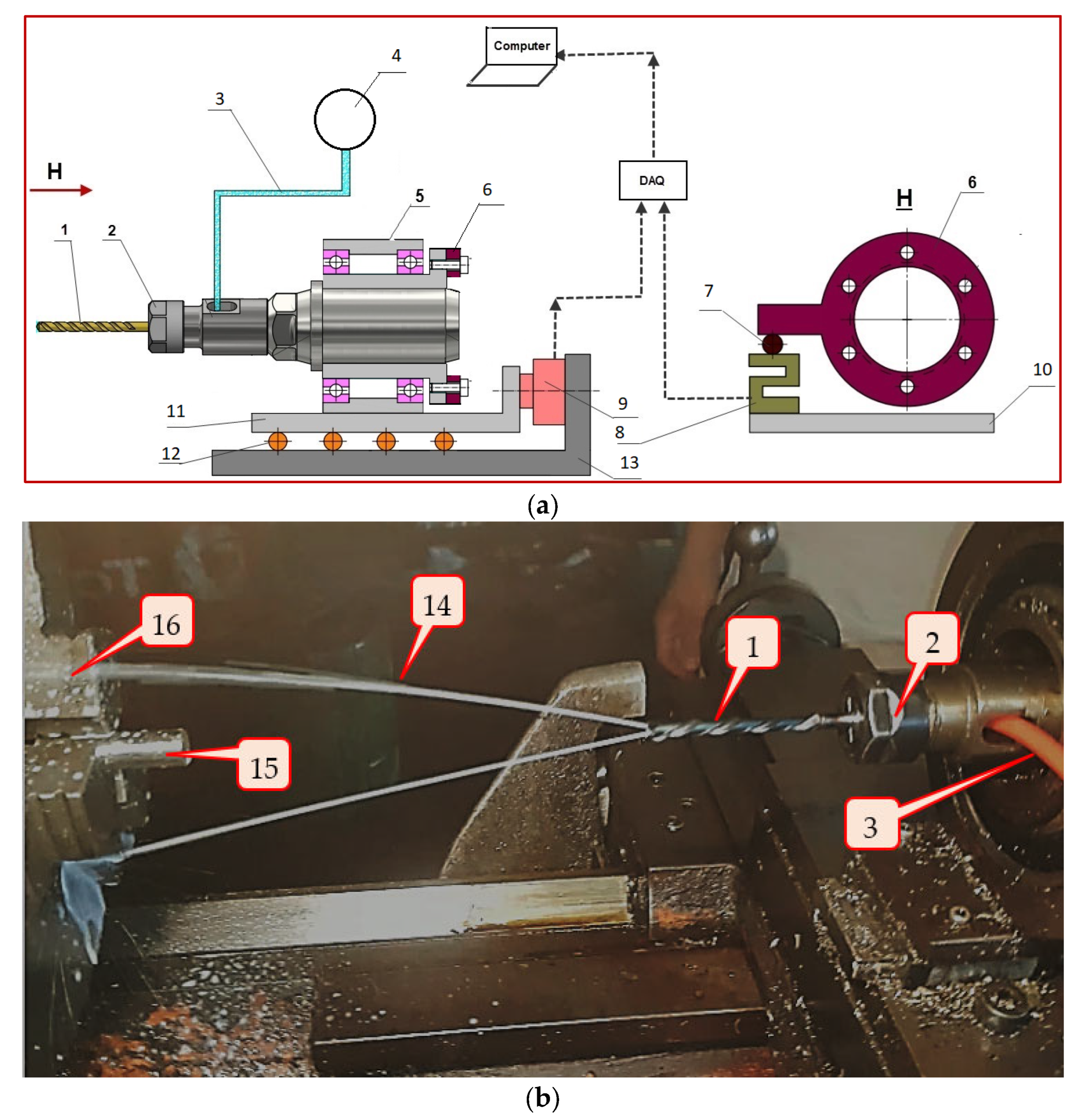
The Nachi Aqua DEXOH8D drill bit with a 5-mm diameter, a popular solid carbide drill with two internal coolant holes, was used in this study. The experiments were implemented on a conventional turning model Takisawa TSL-550. Figure 1 depicts the real setup, where the experimental schema is shown in Figure 1a and the practically implemented system is photographed in Figure 1b.
In Figure 1, the drill bit (1) was clamped inside a collet (2). The cover of the collet has a slot as a door so that a plastic tube (3) can go through to provide the coolant into the drill bit. The drill bit was nested in the plastic tube first, and then the tube was threaded through the slot. A small pump (4), employing a commercial windshield washer pump for automobiles, provided a pressure of 1.5 bars and a flow rate of 0.25 L/min through the two internal holes of the drill bit. The pump was supplied by a 12 V DC voltage with a consumption power of 24 W. The collet body was supported by two bearings placed inside a sleeve (5), providing a rotational ability. A load cell (8) was used to constrain such rotation trend via a disk (6). The signal from that load cell gave the total torque induced in the drilling process. The features were fixed on a sliding bearing (11,12) where the sliding ability was constrained by another load cell (9). The fixture body (13) was fixed on the tool post of the lathe. The workpiece (15) was clamped inside the three-jaw chuck (16) of the lathe. As can be seen from the photograph taken in Figure 1b, the coolant fluid (14) was being provided through the tool bit.
2.2. Materials
The workpieces were made from stock-available bars of AISI SUS 304 in cylindrical form with diameter of 10 mm. Typical characteristics of the AISI SUS 304 material are briefly described in Table 1. Each workpiece was sliced by EDM wire-cut with 40 mm in length. In each experiment, the workpiece was continuously drilled one hole through its length, i.e., with the aspect ratio length-to-diameter of 40/5 = 8.
The graphene nanosheets were synthesized by a plasma-induced method, as described in [20]. The morphology and the detailed structure of the graphene nanosheets were analyzed using transmission electron microscopy (TEM, JEM-2100F, JEOL, Japan). The graphene sheets had a thickness of 2–10 nm and a width of 1–4 μm on average. Their thermal conductivity is about 3000 (W/(m.K), much larger than that of AISI SUS 304 stainless steel.
The soluble oil Caltex Aquatex 3180 was selected as a base fluid in this study. This is a soluble oil which forms a high-stability, milky white fluid when mixed with water, and is commonly used as a typical lubricant in various machining operations.
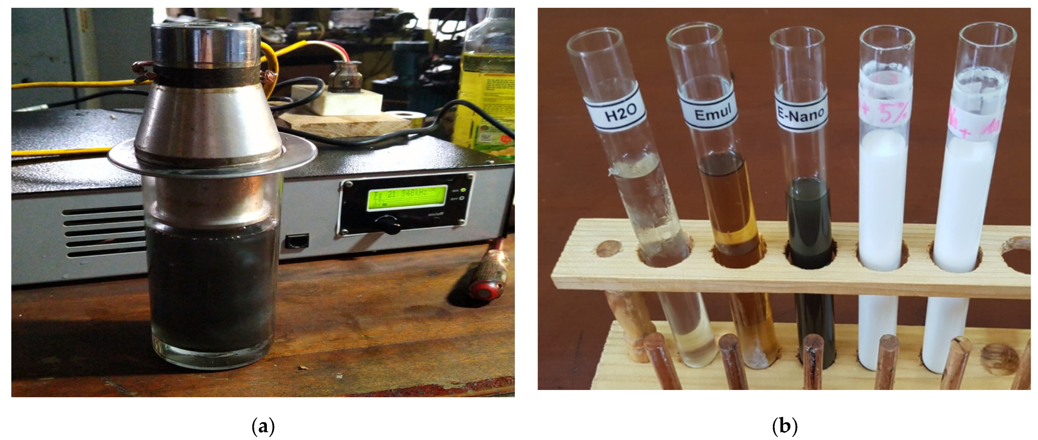
The first step of the lubricant preparation is mixing the nano particles with the base medium. Because graphene nanoparticles are insoluble in emulsion, it is required to use an ultrasonic cleaner with a horn to disperse the nano particles into the emulsion fluid, as shown in Figure 2a. In this stage, the ultrasonication with ultrasonic frequency 28 kHz for 30 min was performed to ensure uniform distribution of the nanoparticles into the emulsion medium. The based fluid of emulsion mixing with nanoparticles (E-Nano) with a scale of approximately 0.1 wt%, i.e., 100 mg nano particle mixing with 100 mL emulsion. The mixed fluid of 0.1 wt% has a dark color as shown in Figure 2b, where other media are shown as reference. In this figure, the fluids shown from left to right include water (H2O as labeled in the Figure), base emulsion (Emul), Nano-emulsion (E-Nano), the nano-emulsion mixing with tap water at 5% and 10% scales, respectively.
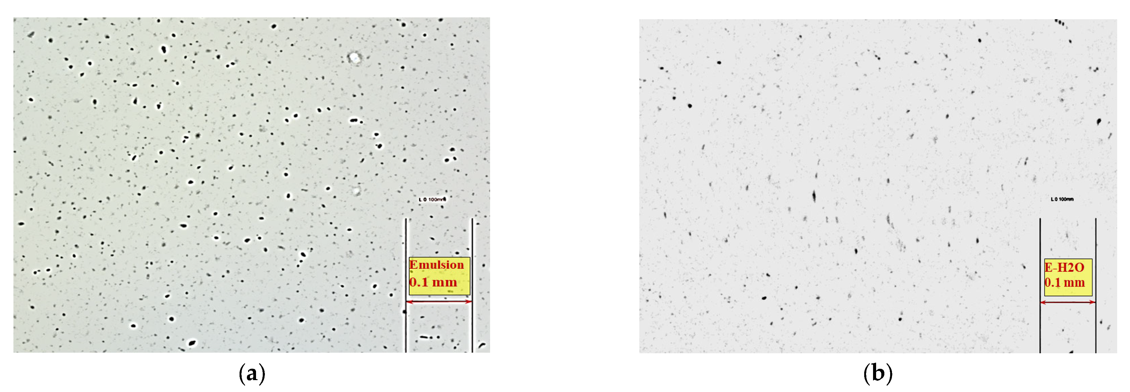
In the second step, the nano-emulsion was then stirred with normal tap water. As the emulsion was soluble into the water, the final lubricant fluid can be easily made with a little care of the proportion of each content as preferred. A scale of 10% emulsion and 90% water as a typical proportion, recommended by manufacturers, was used in this study. The 5% emulsion fluid was made for reference only. It was revealed that the nano particle was not clearly observed in the micrograph of the mixed fluid at 5% emulsion. In order to check if the nanosheets were completely dispersed into the fluid, micrographs of the fluids were taken at 24 h after the mixing was completed, as shown in Figure 3, using an Insize microscope with a scale of 100×. As can be seen in Figure 3a, the nanosheets scattered successfully in the base emulsion. The micrograph of the final nano-fluid made of water (90%) and nano-emulsion (10%) was shown in Figure 3b. As can be seen, the nanosheets appeared in dark dots reflecting that their distribution into the fluid was successful and without agglomerations, even at 24 h after mixing.
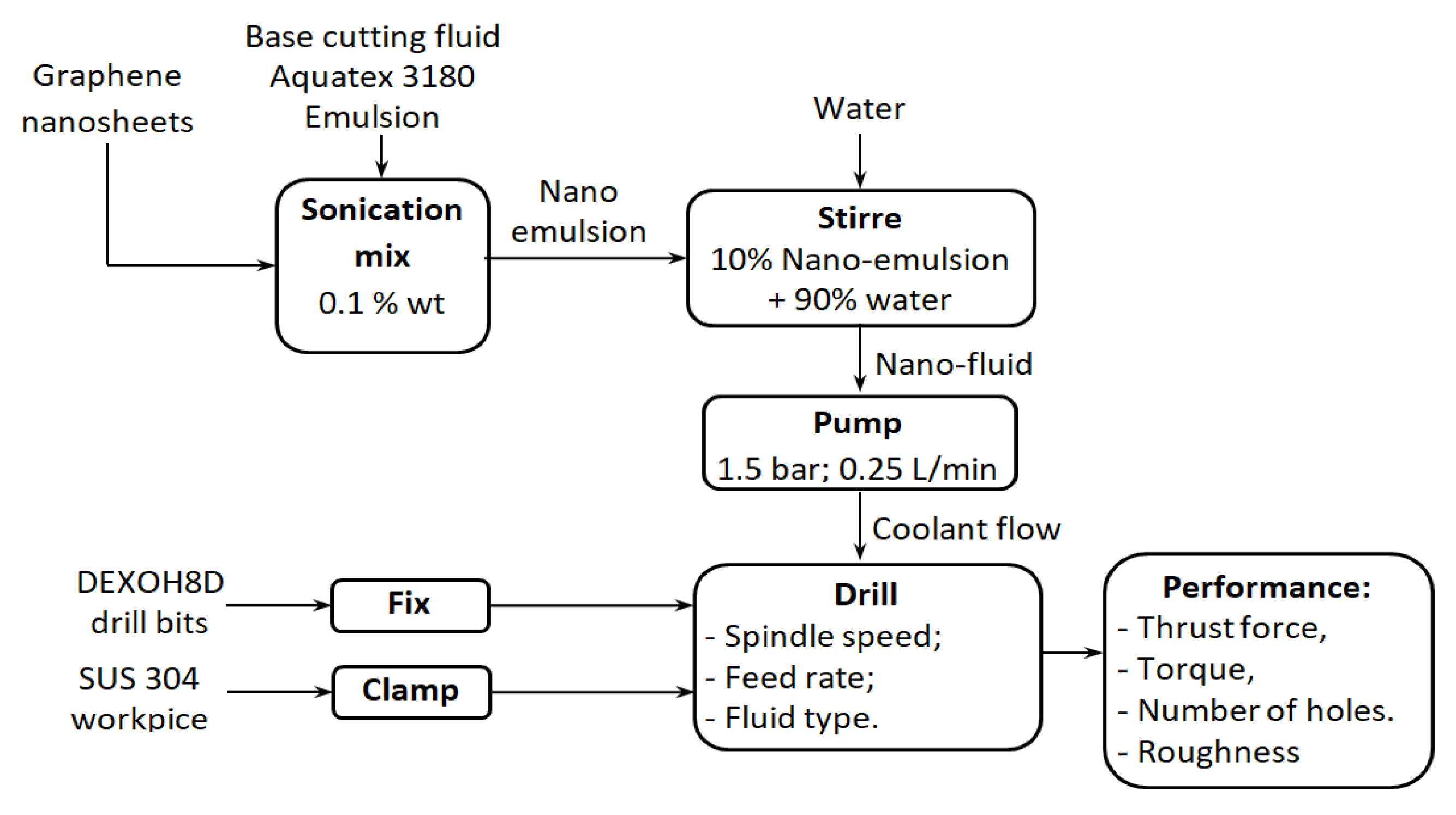
The emission preparation and drilling experiment processes are summarized in the schematic chart in Figure 4. In this study, the nano fluid mixed from nano-emulsion 0.1% wt and tap water with the scale of 10% in volume was applied as the nano-fluid-emulsion (FE) lubricant.
2.3. The Experiment Design
In each cutting test, the fluid was pumped into the cutting zone via the internal coolant holes of the drill bit. The effect of the nano-lubricant to enhance the cutting performance was evaluated by comparing the thrust force, drilling torque, the chip profile, and the number of holes successfully completed with those of the cutting using typical emulsion lubricant.
Four sets of experiments were designed and implemented in this study. The first set, named the pilot tests, was done for two types of coolant fluid: (1) flooded lubricant using emulsion-water fluid (FE) and (2) nano-emulsion-water (FE+Nano). The ability to complete the through hole was used as a criterium to evaluate the drilling capacity of the two coolant types. In the second set, the main effects of cutting speed, feed rate and the lubricant type on the thrust force and the drilling torque were evaluated by means of factorial design. In the third experimental set, a Taguchi design was applied to quickly carry out the proper selection of the cutting parameters using the nano-lubricant. Finally, a validation test was created by applying the selected parameters.
It is noted that although the drill bit can be used for drilling AISI 304 stainless steel with L/D > 5, the tool manufacturer recommends that peck drilling with step feeds of 0.2D to 1D should be applied. However, all of the tests in this study were set in more critical conditions compared to the typical recommendations. In other words, all through holes with L/D = 8 were continuously drilled, without pecking. Each test used a new drill bit. The investigated range of cutting parameters was selected based on the manufacturer recommendations and literature [2,21].
3. Results and Discussions
3.1. Pilot Tests
The pilot tests were implemented to check the ability to successfully complete the deep hole on the workpiece. Each test used a new drill bit. Table 2 represents the results obtained.
As can be seen from Table 2, the first lubricant method using typical emulsion was able to complete the whole hole only at the low feed rate of 0.05 mm/rev for both spindle speeds of 300 and 550 rpm. At higher feed rate (0.07 mm/rev), this method of lubricant supplying was not able to finish the whole test. Here, the tool bits were broken just when drilling the first hole. In contrasts, the drilling processes using lubricant of emulsion-added nano sheets were successfully completed for all investigated cutting parameters.
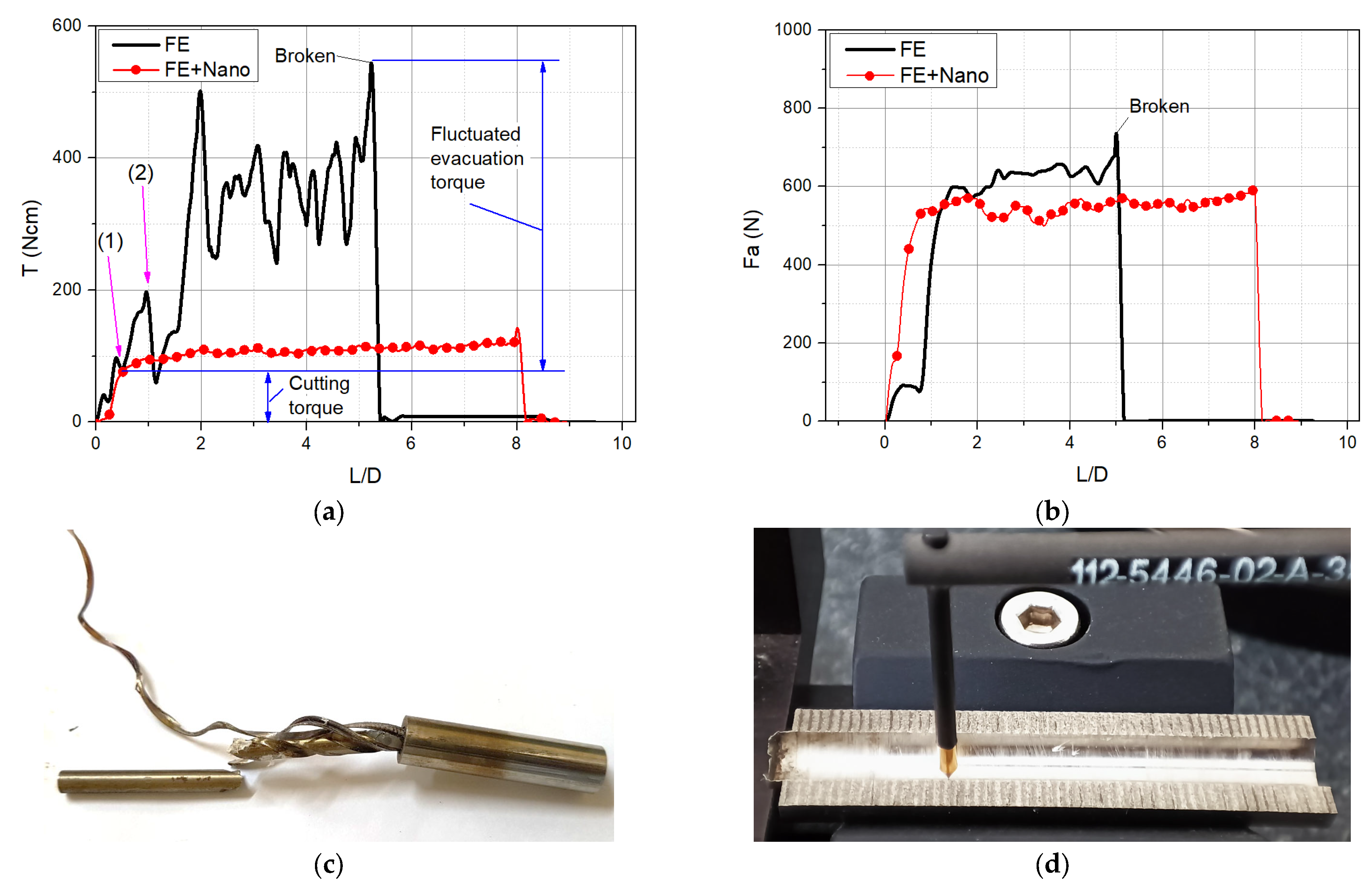
Looking at the torque and the thrust force, Figure 5a,b illustrates such signals obtained at the spindle speed of 550 rpm and feed rate of 0.07 mm/rev under the two lubricant media, with respect to the length-to-diameter ratio (L/D). The broken drill bit stuck inside the workpiece under FE lubricant is shown in Figure 5c, whereas a completed hole under FE+Nano lubricant is represented in Figure 5d for reference.
In Figure 5a, the drilling torques induced were overplot on the same coordinate system. As it can be observed, the torque under emulsion lubricant was significantly increased after the tool engaged the workpiece. Generally speaking, in a deep drilling process, the torque can be extracted into two components: the cutting torque, considered to be constant during the task, and the evacuation chip, which is induced due to the chip jammed inside the hole (See [22,23,24] for examples). In this side view, the evacuation torque induced under the emulsion lubricant (FE) appeared largely as fluctuation. This phenomenon reflects the fact that the chips are mostly jammed and difficult to evacuate from the hole being drilled. The large and fluctuated torque in FE lubricant resulted in the tool breakage (at L/D~5) before completing the whole drilling depth (L/D = 8). Here, the maximum torque of 550 Ncm can be considered as a critical torque which can destroy the drill bit. In contrast, the chip evacuation torque under nano-emulsion lubricant (FE+Nano) was slightly and linearly increased the deeper the hole until the end of the process (L/D = 8), reflecting that significantly less friction was induced among the chips, the flutes, and the hole wall. A smooth variation of the chip evacuation torque until the hole drilling was completed illustrated the outstanding effect of the nano addition into the lubricant. A higher thrust force under FE lubricant compared to that under FE+Nano was also found, as shown in Figure 5b. However, the difference in thrust force between the breaking and the normal situation was not as large as that of the torque. Hence, the drilling torque was chosen as the critical condition to carry out the proper cutting parameters in the rest of this study.
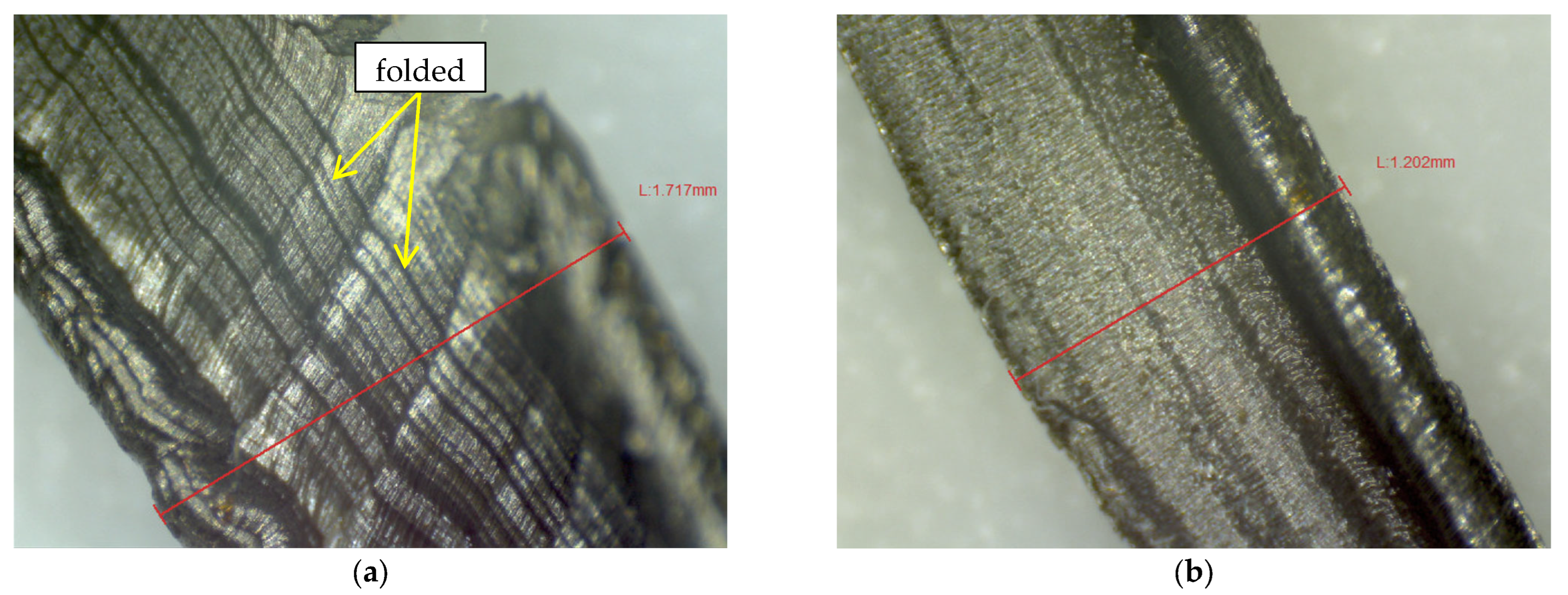
The effect of nanoparticles on reducing the friction induced in chip evacuation can be found in the chip images. In Figure 6, two micromorphology photographs of the chips induced under FE and FE+Nano lubricants are presented, respectively. As can be seen in Figure 6a, the chip induced under the typical emulsion lubricant (FE) has a surface topology of many large folds of the metal fibers, reflecting the high friction acting on the chip, preventing its evacuation. In contrast, the chip of FE+Nano shown in Figure 6b has a much finer topology, and the folds are almost invisible. This phenomenon also reflects the outstanding effect on chip evacuation of the nano particle added into the FE+Nano lubricant. Additionally, it was interesting to observe that the width of the chip induced from FE+Nano was smaller compared to that of the chip from FE. This would be the effect of larger friction preventing the chip evacuation in FE, resulting in more compressive chips in FE compared to those in FE+Nano. Further study for mathematical calculation and validation should be made to carefully examine these phenomena.
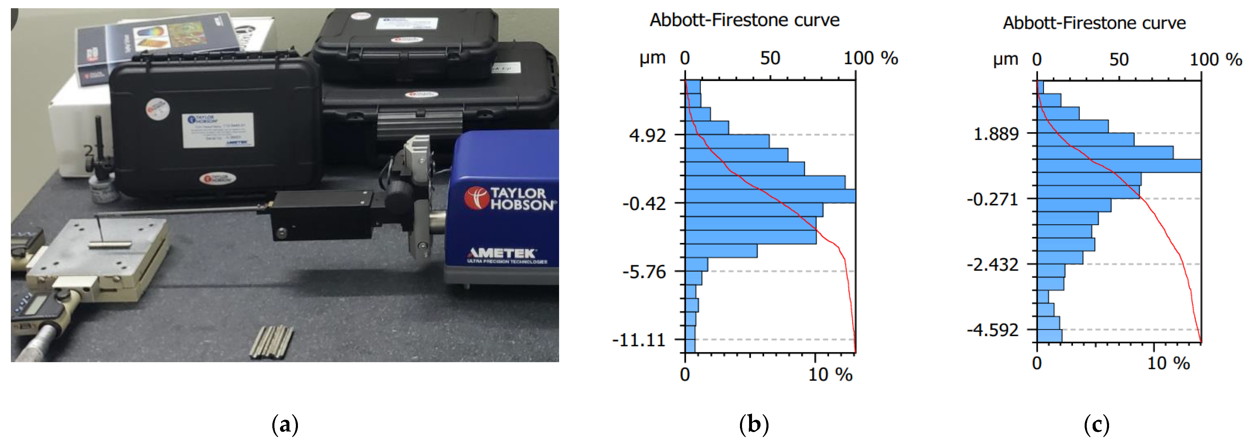
The outstanding effects of nano-lubricants on the chip evacuation would also improve the surface roughness of the drilled holes. In order to check these influences, the roughness of the holes made under FE and FE+Nano were measured by a Taylor Hobson device, as shown in Figure 7a. Each drilled workpiece was axially sliced into two identical parts and then the roughness average values were obtained (see the measurement setup in Figure 5b). The roughness distribution of the holes induced under FE and FE+Nano are represented in Figure 7b,c, respectively. The results revealed that the drilling using FE+Nano lubricant induced better holes, with an average roughness of about 1.465 µm, compared that of 2.819 µm from typical FE lubricant.
3.2. Effects of Cutting Parameters and Lubricant
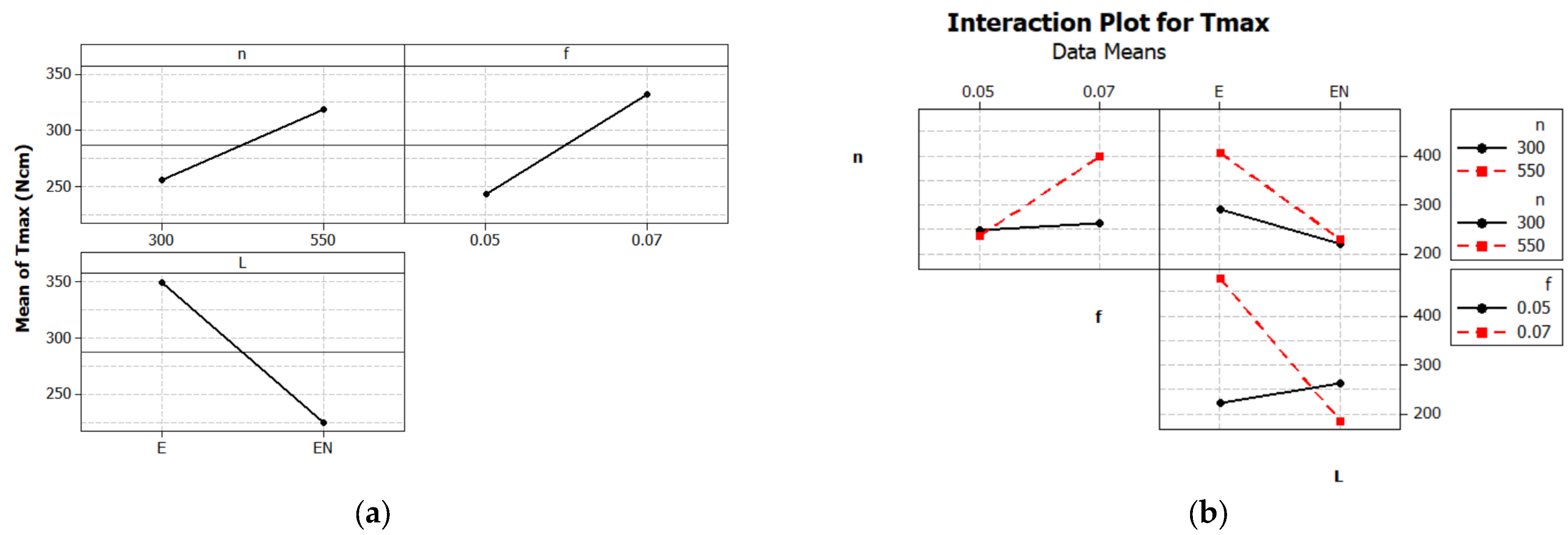
In this section, the effects of the lubricant method (L), the spindle speed (n), and the feed rate and their interaction influences on the maximum torque are all examined, as shown in Figure 8.
The main effect plot is used in conjunction with an analysis of variance and design of experiments to examine differences among level means of the maximum torque (Tmax) for three factors, including the Lubricant (L), spindle speed (n), and feed rate (f). Generally, a main effect is present when different levels of a factor affect the response Tmax differently. As can be seen in Figure 8a, all three factors, the lubricant, the spindle speed, and the feed rate, have significant effects on the response Tmax. Here, the largest effect came from the lubricant method, then the feed rate, and finally, the spindle speed. Regarding the lubricant supplying, the Emulsion-Nano (EN) significantly dropped down the response Tmax with respects to the emulsion lubricant. Besides, increasing spindle speed and feed rate both resulted in producing maximum torque.
Generally, an interaction effect between two factors is present when the response at a factor level depends upon the level of other factors. Parallel lines in the interaction plot indicate no interaction. The greater the departure of the lines from the parallel state, the higher the interaction effect between corresponding factors. As can be seen in Figure 8b, all of the three investigated factors have interaction effects on each other. A combination of higher spindle speed and larger feed rate produced much larger torque. However, it is interesting to see that using emulsion-nano brought about much smaller torque for such combination. This interaction effect should be evaluated in detail to select proper cutting parameters when applying the emulsion-nano lubricant to obtain the best use, as shown in the next sub-section.
3.3. Selection of Cutting Parameters
In order to quickly select proper cutting parameters when applying emulsion-nano lubricant, a Taguchi design of experiment design was applied. Taguchi designs use orthogonal arrays, allowing to investigate each effect independently from the others, and thus can reduce the time and the experiment cost.
In this study, the two control factors, each with three levels, were selected as shown in Table 3.
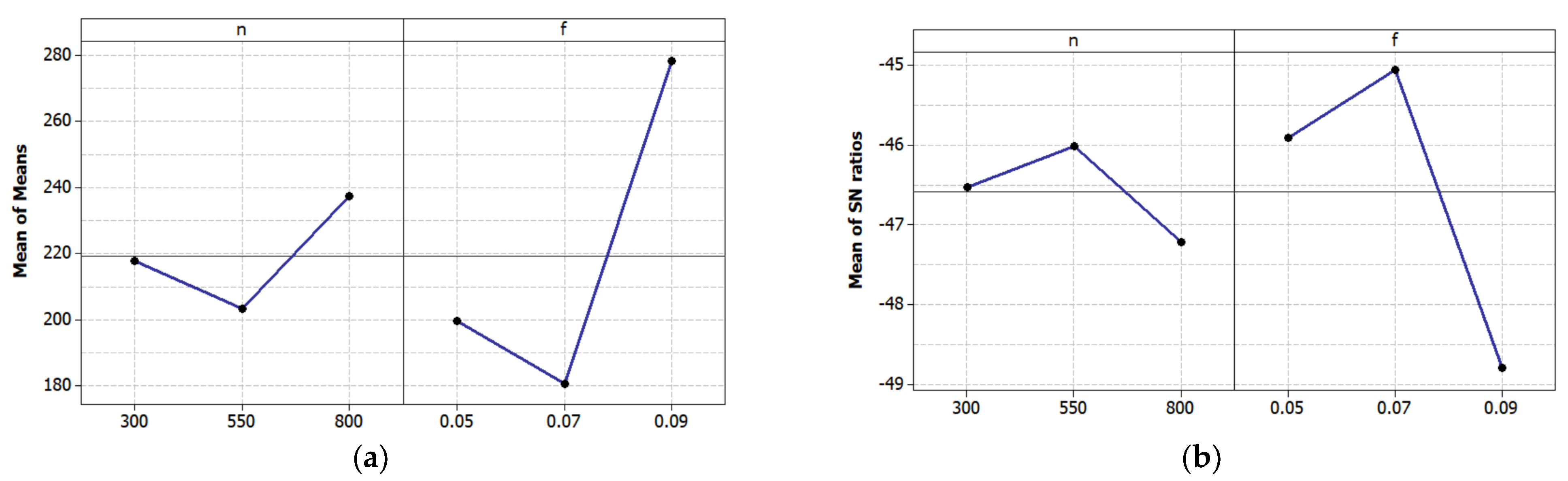
A standard Taguchi experimental plan L9 was chosen to optimize the experimental conditions. The response is the largest value of the drilling torque in each test. As the aim is to minimize such torque, the smaller-is-better signal-to-noise (S/N) ratio was selected. The selected factor levels will be ones that produce the smallest mean. Besides, in Taguchi experiments, it is recommended to choose the maximized S/N ratio. The results of the experiments are represented in Figure 9.
As can be seen in Figure 9a, the set of cutting parameters of n = 550 rpm and f = 0.07 mm/rev provides the smallest value for the torque compared to the other sets. The largest S/N ratio of this set in Figure 9b confirmed this observation. The validation test of applying this parameter selection is shown in the next sub-section.
3.4. Validation Test
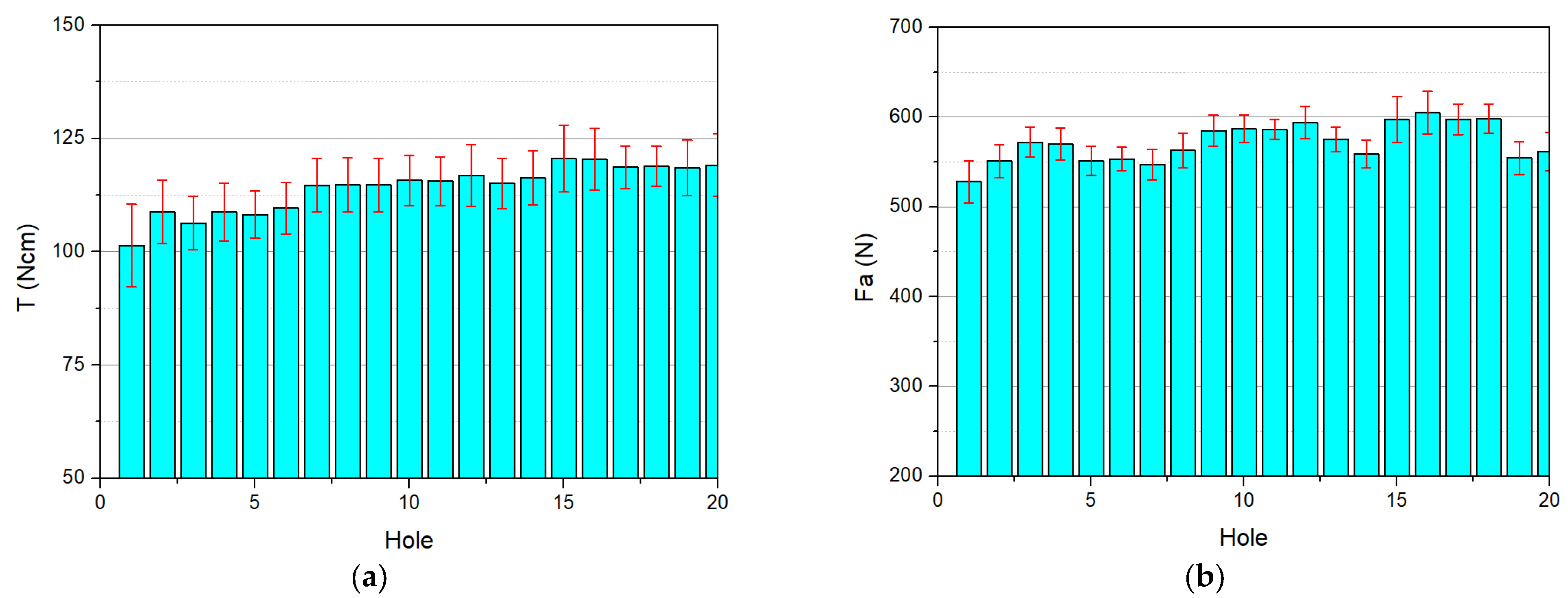
In this test, the multi-hole drilling was applied with the cutting parameters selected above, i.e., with n = 550 rpm and f = 0.07 mm/rev under the internal lubricant of nano-emulsion. The experimental results revealed that using one drill bit can successfully complete as many as 20 holes. Figure 10 represents the drilling torque and thrust force induced in drilling each hole.
Overall, both the torque and the thrust force were slightly increased when drilling the later holes compared to those of the first hole, where the drill bit was still totally new. However, the largest torque and thrust force, induced at the 15th and 16th holes, were only around 125 Ncm and 625 N, respectively. Such torque of 125 Ncm is much smaller than the critical torque of 550 Ncm (See Figure 4 above), thus it can be confirmed that the drill bit was under a good safety condition. The value of 625 N of thrust force was also in the normal range of the normal situation, compared to about 750 N thrust force when the tool was broken. Compared to the cutting performance when applying the emulsion without nanoparticles, using nano-emulsion can complete the deep hole and finish 20 holes with the torque reduced by as much as 4.4 times, and the thrust force reduced by 1.2 times. This observation confirmed that the enhancement of adding nanoparticles in lubricating the deep hole drilling was significantly effective for hard-to-cut materials.
4. Conclusions
A new method of applying nano-lubricant in deep drilling with the length-to-diameter of eight for stainless steel was proposed, implemented, and evaluated in this study. The following remarkable issues can be noted:
- -
- The lubricant was made in two stages: first, the nano particles were dispersed into the emulsion fluid by ultrasonic vibration for 30 min; the obtained fluid was then made with the percentage of 10% emulsion and 90% water.
- -
- Four sets of experiments were implemented. In the pilot test, it was found that deep hole drilling with L/D = eight can be successfully performed using nano-lubricant at the feed rate of 0.07 mm/rev, but the typical lubricant could not. The effects of spindle speed, the feed rate, and the lubricant types were then examined in the second test. It was found that all of three factors have significant effects on the drilling performance, where the lubricant is the most important factor. In the third test for selecting proper cutting parameters, the spindle speed of 550 rpm and feed rate of 0.07 mm/rev under nano-lubricant were found to be the best choice. Finally, the validation test revealed that applying nano-lubricant can reduce the drilling torque and thrust force by 4.4 and 1.2 times, respectively, compared to those when applying typical lubricant. The nano-lubricant provided an ability of continuously drilling 20 holes without failure, whereas the typical lubricant cannot complete even one hole in the same cutting parameters.
The method of using nano-lubricant can be applied to deep drilling of other hard-to-cut materials. Further studies can be investigated to evaluate the effectiveness of the method compared with other methods as well as checking with the other fields of applications, such as milling, turning, and drilling with other materials.
Author Contributions
Conceptualization and methodology, V.-D.N.; experimental design and implementation, T.-D.H. and T.-H.M.; writing—review and editing, all authors; project administration, V.-D.N. All authors have read and agreed to the published version of the manuscript.
Funding
This research was funded by the Vietnam Ministry of Education and Training, grant number B2020-TNA-01.
Institutional Review Board Statement
Not applicable.
Informed Consent Statement
Not applicable.
Data Availability Statement
Not applicable.
Acknowledgments
The authors would like to express their thanks to Thai Nguyen University of Technology, Thai Nguyen University, and Thai Nguyen School for gifted students for their support. Funding from the Vietnam Ministry of Education and Training is acknowledged.
Conflicts of Interest
The authors declare no conflict of interest. The funders had no role in the design of the study; in the collection, analyses, or interpretation of data; in the writing of the manuscript, or in the decision to publish the results.
References
- Kaladhar, M.; Subbaiah, K.V.; Rao, C.H.S. Machining of austenitic stainless steels—A review. Int. J. Mach. Mach. Mater. 2012, 12, 178. [Google Scholar] [CrossRef]
- Khan, S.A.; Shamail, S.; Anwar, S.; Hussain, A.; Ahmad, S.; Saleh, M. Wear performance of surface treated drills in high speed drilling of AISI 304 stainless steel. J. Manuf. Process. 2020, 58, 223–235. [Google Scholar] [CrossRef]
- Tian, Y.; Zou, P.; Yang, X.; Kang, D. Study on chip morphology and surface roughness in ultrasonically assisted drilling of 304 stainless steel. Int. J. Adv. Manuf. Technol. 2020, 108, 2079–2090. [Google Scholar] [CrossRef]
- Arif, R.; Fromentin, G.; Rossi, F.; Marcon, B. Investigations on drilling performance of high resistant austenitic stainless steel. J. Manuf. Processes 2020, 56, 856–866. [Google Scholar] [CrossRef]
- Sultan, A.Z.; Sharif, S.; Nor, F.M.; Kurniawan, D. Minimum quantity of lubricant drilling of stainless steel using refined palm olein: Effect of coating tool on surface roughness and tool wear. Procedia Manuf. 2019, 30, 427–434. [Google Scholar] [CrossRef]
- Pradeep Kumar, M.; Shakeel Ahmed, L. Drilling of AISI 304 Stainless Steel under Liquid Nitrogen Cooling: A Comparison with Flood Cooling. Mater. Today Proc. 2017, 4, 1518–1524. [Google Scholar] [CrossRef]
- Eltaggaz, A.; Deiab, I. Comparison of between direct and peck drilling for large aspect ratio in Ti-6Al-4V alloy. Int. J. Adv. Manuf. Technol. 2019, 102, 2797–2805. [Google Scholar] [CrossRef]
- Polli, M.L.; Cardoso, M.J. Effects of process parameters and drill point geometry in deep drilling of SAE 4144M under MQL. J. Braz. Soc. Mech. Sci. Eng. 2018, 40, 137. [Google Scholar] [CrossRef]
- Sujan Kumar, M.; Deivanathan, R. Effect of process parameters on drilling—An overview. Mater. Today Proc. 2021, 46, 1401–1406. [Google Scholar] [CrossRef]
- Kanagaraju, T.; Boopathy, S.; Gowthaman, B. Effect of cryogenic and wet coolant performance on drilling of super duplex stainless steel (2507). Mater. Express 2020, 10, 81–93. [Google Scholar] [CrossRef]
- Heinemann, R.; Hinduja, S.; Barrow, G.; Petuelli, G. Effect of MQL on the tool life of small twist drills in deep-hole drilling. Int. J. Mach. Tools Manuf. 2006, 46, 1–6. [Google Scholar] [CrossRef]
- Gandarias, A.; Lopez de Lacalle, L.N.; Aizpitarte, X.; Lamikiz, A. Study of the performance of the turning and drilling of austenitic stainless steels using two coolant techniques. Int. J. Mach. Mach. Mater. 2008, 3, 1–17. [Google Scholar] [CrossRef]
- Stephenson, D.A.; Hughey, E.; Hasham, A.A. Air flow and chip removal in minimum quantity lubrication drilling. Procedia Manuf. 2019, 34, 335–342. [Google Scholar] [CrossRef]
- Nouzil, I.; Eltaggaz, A.; Deiab, I.; Pervaiz, S. Toxicity of Nanoparticles Used in Minimum Quantity Lubrication (MQL) Machining: A Sustainability Analysis. In Proceedings of the ASME 2020 International Mechanical Engineering Congress and Exposition, Virtual Conference, 16–19 November 2020. [Google Scholar]
- Naik, M.; Manjunath, L.; Koti, V.; Lakshmikanthan, A.; Koppad, P.G.; Kumaran, S.P. Al/Graphene/CNT hybrid composites: Hardness and sliding wear studies. FME Trans. 2021, 49, 414–421. [Google Scholar] [CrossRef]
- Alipour, M.; Keshavamurthy, R.; Koppad, P.G.; Shakiba, A.; Reddy, N.C. Investigation of Microstructure and Mechanical Properties of Cast Al–10Zn–3.5Mg–2.5Cu Nanocomposite Reinforced with Graphene Nano Sheets Produced by Ultrasonic Assisted Stir Casting. Int. J. Met. 2022, 23, 1–22. [Google Scholar] [CrossRef]
- Kadirgama, K. A comprehensive review on the application of nanofluids in the machining process. Int. J. Adv. Manuf. Technol. 2021, 115, 2669–2681. [Google Scholar] [CrossRef]
- Korkmaz, M.E.; Gupta Kumar, M.; Krolczyk, G.M.; Maruda, R.W.; Li, Z. Effect of nanoparticles as a lubricants in nano-MQL machining of metallic materials: A review. In Proceedings of the 2021 6th International Conference on Nanotechnology for Instrumentation and Measurement (NanofIM), Opole, Poland, 25–26 November 2021. [Google Scholar]
- Hoang, T.-D.; Ngo, Q.-H.; Chu, N.-H.; Mai, T.-H.; Nguyen, T.; Ho, K.-T.; Nguyen, D. Ultrasonic assisted nano-fluid MQL in deep drilling of hard-to-cut materials. Mater. Manuf. Process. 2021, 37, 712–721. [Google Scholar] [CrossRef]
- Van Truong, N.; Quoc Dung, N.; Nhat Huy, N.; Van Hao, P.; Van Thanh, D. Ultrasonic-Assisted Cathodic Plasma Electrolysis Approach for Producing of Graphene Nanosheets. In Sonochemical Reactions; Karakuş, S., Ed.; InTech Open: London, UK, 2020. [Google Scholar]
- Çaydaş, U.; Hasçalık, A.; Buytoz, Ö.; Meyveci, A. Performance Evaluation of Different Twist Drills in Dry Drilling of AISI 304 Austenitic Stainless Steel. Mater. Manuf. Process. 2011, 26, 951–960. [Google Scholar] [CrossRef]
- Mellinger, J.C.; Ozdoganlar, B.; Devor, R.E.; Kapoor, S.G. Modeling Chip-Evacuation Forces Predict. Chip-Clogging Drilling. J. Manuf. Sci. Eng. 2002, 124, 605. [Google Scholar] [CrossRef]
- Chu, N.-H.; Nguyen, D.-B.; Ngo, N.-K.; Nguyen, V.-D.; Tran, M.-D.; Vu, N.-P.; Ngo, Q.-H.; Tran, T.-H. A New Approach to Modelling the Drilling Torque in Conventional and Ultrasonic Assisted Deep-Hole Drilling Processes. Appl. Sci. 2018, 8, 2600. [Google Scholar] [CrossRef] [Green Version]
- Chu, N.-H.; Nguyen, V.-D.; Ngo, Q.-H. Machinability enhancements of ultrasonic-assisted deep drilling of aluminum alloys. Mach. Sci. Technol. 2020, 24, 112–135. [Google Scholar] [CrossRef]
Figure 1.
The experimental setup: (a) in arranged schema and (b) at realized photograph.

Figure 2.
The nano-fluid preparation: (a) ultrasonic vibration to disperse nano sheets into emulsion oil and (b) the final fluids after 24 h since the mixing was completed.
Figure 2.
The nano-fluid preparation: (a) ultrasonic vibration to disperse nano sheets into emulsion oil and (b) the final fluids after 24 h since the mixing was completed.

Figure 3.
Micrographs of: (a) the emulsion oil with graphene nanosheets dispersed and (b) the nano-fluid mixed from nano-emulsion-water. The photographs were taken after 24 h since the mixing process was completed.
Figure 3.
Micrographs of: (a) the emulsion oil with graphene nanosheets dispersed and (b) the nano-fluid mixed from nano-emulsion-water. The photographs were taken after 24 h since the mixing process was completed.

Figure 4.
Schematic chart of emission preparation and drilling experiments.

Figure 5.
The results obtained from the two lubricant media: (a) the total torque; (b) the thrust force; (c) the broken drill bit and workpiece and (d) the completed hole in roughness measurement.
Figure 5.
The results obtained from the two lubricant media: (a) the total torque; (b) the thrust force; (c) the broken drill bit and workpiece and (d) the completed hole in roughness measurement.

Figure 6.
Photographs of the chips induced: (a) under the typical emulsion lubricant (FE) and (b) under nano-emulsion lubricant (FE+Nano).
Figure 6.
Photographs of the chips induced: (a) under the typical emulsion lubricant (FE) and (b) under nano-emulsion lubricant (FE+Nano).

Figure 7.
Roughness of the drilled holes: (a) under the typical emulsion lubricant (FE) and (b,c) under nano-emulsion lubricant (FE+Nano).
Figure 7.
Roughness of the drilled holes: (a) under the typical emulsion lubricant (FE) and (b,c) under nano-emulsion lubricant (FE+Nano).

Figure 8.
Factorial experimental results of the maximum torque: (a) the main effect plot and (b) the interaction plot.
Figure 8.
Factorial experimental results of the maximum torque: (a) the main effect plot and (b) the interaction plot.

Figure 9.
Taguchi experimental results: (a) the mean values and (b) the S/N ratios.

Figure 10.
The drilling performance in mean and distribution: (a) the torque and (b) the thrust force. The selected spindle speed of 550 rpm and feed rate of 0.07 mm/rev under nano-emulsion lubricant were applied.
Figure 10.
The drilling performance in mean and distribution: (a) the torque and (b) the thrust force. The selected spindle speed of 550 rpm and feed rate of 0.07 mm/rev under nano-emulsion lubricant were applied.


Table 1.
Main properties of AISI SUS 304 stainless steel.
| Property Name | Young’s Modulus | Brinell’s Hardness | Tensile Strength | Elongation at Break | Poisson’s Ratio | Density |
|---|---|---|---|---|---|---|
| Values (Units) | 190–203 (GPa) | 215 HB | 500–700 MPa | 45% | 0.265 | 8 g/cm3 |
| Property Name | Shear Modulus | Shear Strength | Melting Temperature | Thermal Conductivity | Specific Heat Capacity | Thermal Expansion Coefficient |
| Values (Units) | 81 GPa | 690 MPa | 14,500 C | 16.2 W/mK | 490 J/kgK | 17.2 × 10⁻⁶/K |
Table 2.
Cutting ability of the two lubricant methods.
| Test Number | Speed (rpm) | Feed Rate (mm/rev) | FE | FE+Nano |
|---|---|---|---|---|
| 1 | 300 | 0.05 | ✓ | ✓ |
| 2 | 550 | 0.05 | ✓ | ✓ |
| 3 | 300 | 0.07 | ✘ | ✓ |
| 4 | 550 | 0.07 | ✘ | ✓ |
Table 3.
Experimental variables and their levels.
| Levels | Low | Medium | High | |
|---|---|---|---|---|
| Parameters | ||||
| Spindle speed, n (rpm) | 300 | 550 | 800 | |
| Feed rate, f (mm/rev) | 0.05 | 0.07 | 0.09 | |
Publisher’s Note: MDPI stays neutral with regard to jurisdictional claims in published maps and institutional affiliations. |
© 2022 by the authors. Licensee MDPI, Basel, Switzerland. This article is an open access article distributed under the terms and conditions of the Creative Commons Attribution (CC BY) license (https://creativecommons.org/licenses/by/4.0/).
Share and Cite
MDPI and ACS Style
Hoang, T.-D.; Mai, T.-H.; Nguyen, V.-D. Enhancement of Deep Drilling for Stainless Steels by Nano-Lubricant through Twist Drill Bits. Lubricants 2022, 10, 173. https://0-doi-org.brum.beds.ac.uk/10.3390/lubricants10080173
AMA Style
Hoang T-D, Mai T-H, Nguyen V-D. Enhancement of Deep Drilling for Stainless Steels by Nano-Lubricant through Twist Drill Bits. Lubricants. 2022; 10(8):173. https://0-doi-org.brum.beds.ac.uk/10.3390/lubricants10080173
Chicago/Turabian StyleHoang, Tien-Dat, Thu-Ha Mai, and Van-Du Nguyen. 2022. "Enhancement of Deep Drilling for Stainless Steels by Nano-Lubricant through Twist Drill Bits" Lubricants 10, no. 8: 173. https://0-doi-org.brum.beds.ac.uk/10.3390/lubricants10080173
Note that from the first issue of 2016, this journal uses article numbers instead of page numbers. See further details here.