
Numerical Simulation of Unreinforced Masonry Buildings with Timber Diaphragms


1
École Polytechnique Fédérale de Lausanne (EPFL), School of Architecture, Civil and Environmental Engineering (ENAC), Earthquake Engineering and Structural Dynamics Laboratory (EESD), 1015 Lausanne, Switzerland
2
Résonance Ingénieurs-Conseils SA, 1227 Carouge, Switzerland
*
Author to whom correspondence should be addressed.
Buildings 2021, 11(5), 205; https://0-doi-org.brum.beds.ac.uk/10.3390/buildings11050205
Submission received: 5 April 2021
/
Revised: 19 April 2021
/
Accepted: 22 April 2021
/
Published: 14 May 2021
(This article belongs to the Special Issue Seismic Performance Assessment of Buildings)
Abstract
:Though flexible diaphragms play a role in the seismic behaviour of unreinforced masonry buildings, the effect of the connections between floors and walls is rarely discussed or explicitly modelled when simulating the response of such buildings. These flexible diaphragms are most commonly timber floors made of planks and beams, which are supported on recesses in the masonry walls and can slide when the friction resistance is reached. Using equivalent frame models, we capture the effects of both the diaphragm stiffness and the finite strength of wall-to-diaphragm connections on the seismic behaviour of unreinforced masonry buildings. To do this, we use a newly developed macro-element able to simulate both in-plane and out-of-plane behaviour of the masonry walls and non-linear springs to simulate wall-to-wall and wall-to-diaphragm connections. As an unretrofitted case study, we model a building on a shake table, which developed large in-plane and out-of-plane displacements. We then simulate three retrofit interventions: Retrofitted diaphragms, connections, and diaphragms and connections. We show that strengthening the diaphragm alone is ineffective when the friction capacity of the wall-to-diaphragm connection is exceeded. This also means that modelling an unstrengthened wall-to-diaphragm connection as having infinite stiffness and strength leads to unrealistic box-type behaviour. This is particularly important if the equivalent frame model should capture both global in-plane and local out-of-plane failure modes.
1. Introduction
Historical unreinforced masonry buildings have proven to be particularly susceptible to earthquakes (e.g., [1,2,3,4,5]). To establish effective seismic risk management strategies and design appropriate retrofitting schemes, simulation tools are required that can reproduce the behaviour of historical unreinforced masonry buildings in their unstrengthened and strengthened configurations.
Different modelling techniques have been adopted to simulate the seismic behaviour of unreinforced masonry buildings, which differ regarding both the level of detail at which the building is modelled and the computational costs of the simulations (e.g. [6,7]). While more detailed techniques, such as the ones used in [8,9,10,11,12], simulate masonry behaviour at a micro-scale, the computational cost limits at present still either the size of the model analysed or the number of simulations. For the simulations in this paper, we chose to use the equivalent frame model approach, which we consider a good compromise between level of detail and computational cost if a large number of analyses are performed [13]. It is also a modelling approach that is widely used in engineering practice, making our findings highly applicable [14]. In equivalent frame models, building facades are idealised as frames consisting of vertical pier elements, horizontal spandrel elements, and nodes [13,15]. This frame idealisation is applicable to buildings with a relatively regular opening layout, such as the layout of many residential masonry buildings [16,17,18].
In equivalent frame models, the response of individual piers and spandrels is captured through macro-elements, which phenomenologically reproduce the force-displacement response of the piers and spandrels. A number of such macro-element models have been proposed for unreinforced masonry elements [15,19,20,21,22,23,24,25,26,27,28,29,30,31,32,33]; a recent review is included in [14]. The simplicity of this modelling approach allows multiple static and dynamic analyses to be performed in a short time, and a large number of performed analyses can address aleatory and epistemic uncertainties [13,34,35,36,37]. However, because all but the most recent macro-elements for unreinforced masonry elements [38] capture only the in-plane and not the out-of-plane response, equivalent frame model analyses were restricted to the global response.
Timber floors and their wall-to-diaphragm connections affect the global response of unreinforced masonry buildings and the formation of local out-of-plane failure modes [1,2,39]. Solarino et al. [40] reviewed wall-to-diaphragm connections common in unreinforced masonry buildings as well as classical and innovative strengthening solutions. The effect of timber floors and their wall-to-diaphragm connections has been investigated experimentally by several research groups through large-scale shake table tests on masonry buildings [41,42,43,44,45,46,47,48,49,50,51,52,53,54,55]. Other studies numerically investigated the effect of diaphragm stiffness on the global nonlinear seismic response of unreinforced masonry buildings by modelling the diaphragms as elastic membranes and using equal DOF (Degree of Freedom) constraints for the wall-to-diaphragm connection [56,57,58,59,60,61,62]. Recent works by Mirra [63] and Trutalli et al. [64] proposed modelling timber floors by an assemblage of elastic truss elements and nonlinear springs, which are assigned as a uniaxial material using Pinching4 of OpenSEES [65] that represents a ’pinched’ load-deformation response and degrades under cyclic loading. The necessary parameters for obtaining an accurate pinching cycle were then calibrated against experimental results.
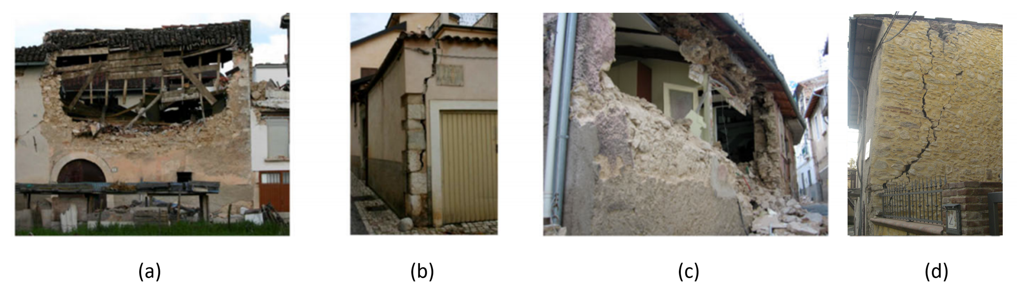
The effect of the quality of the wall-to-diaphragm connection on the seismic response of vernacular masonry buildings was addressed by Ortega et al. through an investigation of the influence of several floor parameters, including the diaphragm stiffness, the beam stiffness and the wall-to-diaphragm and wall-to-beam connections [66]. The masonry was modelled using solid 3D elements and an isotropic total strain rotating crack model. Because this method is computationally expensive, pushover analyses rather than time-history analyses were carried out. The wall-to-beam connections were modelled by imposing equal DOF conditions in combination with different embedment lengths for the beams, and the wall-to-diaphragm connections were modelled either with equal DOF conditions or without any connection. The friction connection was therefore idealised as either infinitely strong or non-existent. The results showed that if a proper connection was lacking, a stiffened diaphragm did not have the expected benefits. First equivalent frame models that used the macro-element by Vanin et al. [38] showed that this new formulation can capture out-of-plane mechanisms of single walls and parts of buildings that involve one-way bending of single elements [67]. Common post-earthquake, out-of-plane damage patterns, such as those shown in Figure 1 illustrate the necessity of correctly modelling this phenomenon.
The objectives of this paper are to show that the latest equivalent frame modelling approach can be used for studying the effects of diaphragm stiffness and wall-to-diaphragm connections and to highlight the importance of explicitly modelling the wall-to-diaphragm connection. More specifically, we make the following two contributions:
- Equivalent frame model for Building 1 of the Pavia test series on stone masonry buildings [47,48]: This test series comprised uni-directional shake-table tests on three stone masonry buildings. Building 1 had a weak diaphragm and wall-to-diaphragm connections that relied only on friction between beams and walls. It developed significant nonlinear in-plane deformations but eventually succumbed to out-of-plane failure. Building 1 has not yet been modelled by an equivalent frame approach, so we close this gap by developing an equivalent frame model for Building 1 and validating it against the experimental results. Buildings 2 and 3 had strengthened diaphragms and wall-to-diaphragm connections. They did not develop any out-of-plane mechanisms and their in-plane response was modelled successfully by Penna et al. [68] using Tremuri [27] and the macro-element by Penna et al. [28].
- Interplay between diaphragm stiffness and unstrengthened wall-to-diaphragm connections: We model the unstrengthened wall-to-diaphragm connection of Building 1 and analyse various configurations using a nonlinear spring with a force capacity that is limited by Coulomb friction. We confirm the finding by Ortega et al. [66] that when a proper connection is lacking, a stiffened diaphragm lacks its beneficial effects. By modelling the connection through a friction connection rather than as fully connected (equal DOF) or disconnected, we show that there is a threshold PGA (Peak Ground Acceleration) value for which the wall-to-diaphragm connections start to slide. For higher PGA values, stiffened diaphragms lose their beneficial effect.
In this paper, we first outline our modelling strategy for unreinforced masonry buildings (Section 2) and establish the equivalent frame model for Building 1 (Section 3). We compare the results of the analyses to the experimental results. We then simulate three simple strengthening interventions that highlight the interplay of diaphragm stiffness and wall-to-diaphragm connection strength (Section 4). Based on these simulations, we formulate recommendations for modelling timber slabs in unreinforced masonry buildings in the final section (Section 5). Finally, we conclude as much as these case studies permit on the effect of the retrofit techniques on the seismic response of unreinforced masonry buildings and formulate future research needs regarding the modelling of timber slabs in equivalent frame models.
2. Equivalent Frame Models for Unreinforced Masonry Buildings with Timber Slabs
Here, we describe the equivalent frame model that we adopted for simulating the seismic behaviour of stone masonry building with timber floors. As our goal is to investigate the role of the timber diaphragm and wall-to-diaphragm connection on the seismic response of unreinforced masonry buildings, we discuss modelling assumptions with regard to these two points in particular detail.
2.1. A Macro-Element for Modelling the in-Plane and out-of-Plane Response of Unreinforced Masonry Piers and Spandrels
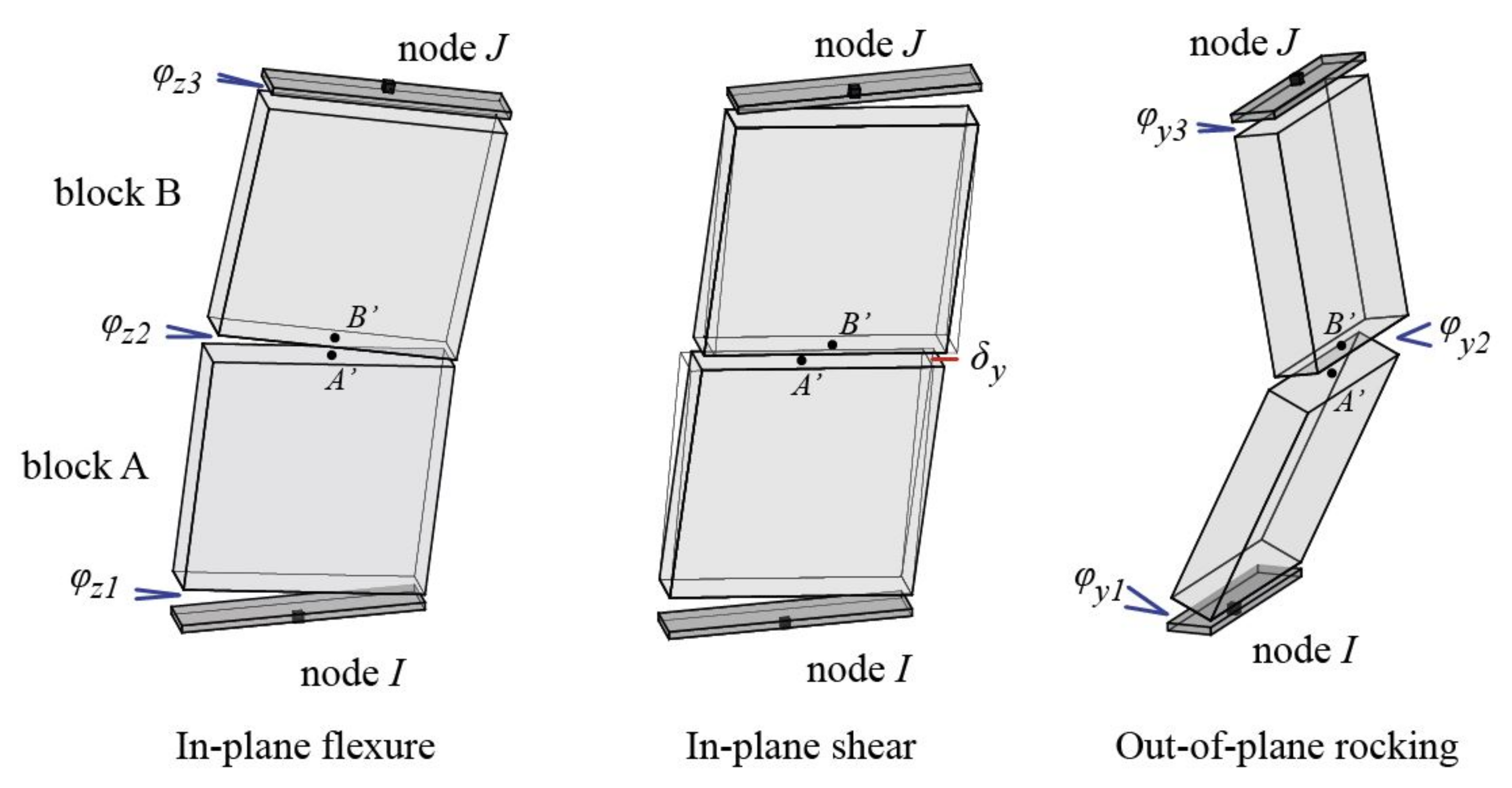
In this study, we use the newly developed macro-element by Vanin et al. [38], which is implemented in OpenSEES [65]. It is the first macro-element for equivalent frame models that can capture the in-plane and out-of-plane behaviour of piers and spandrels by modelling each as a three-node element in three-dimensional space (Figure 2). The element is formulated as a system of two panels, deformable only in shear, rotating around three end sections and where flexural deformations are lumped. The exact equilibrium is ensured at all sections in the deformed configuration using an approximated formulation. The in-plane response of this macro-element is based on the formulation by Penna et al. [28].
With this approach, the in-plane flexural and shear failures and the out-of-plane overturning of the panel can be modelled [38]. The shear model depends explicitly on the axial load applied to the section. The shear strength of the panel is defined by a Mohr-Coulomb failure criterion imposed by a damage-plasticity model describing residual displacements, stiffness degradation, and post-peak strength degradation. The flexural response, both in-plane and out-of-plane, depends directly on the applied section model. In the following, an analytical section model is used, assuming a material without tensile strength and with limited compressive strength with no post-peak degradation. When large lateral displacements are attained, in-plane failure of the panel is imposed.
2.2. Modelling Assumptions for Masonry Walls and Wall-to-Wall Connections
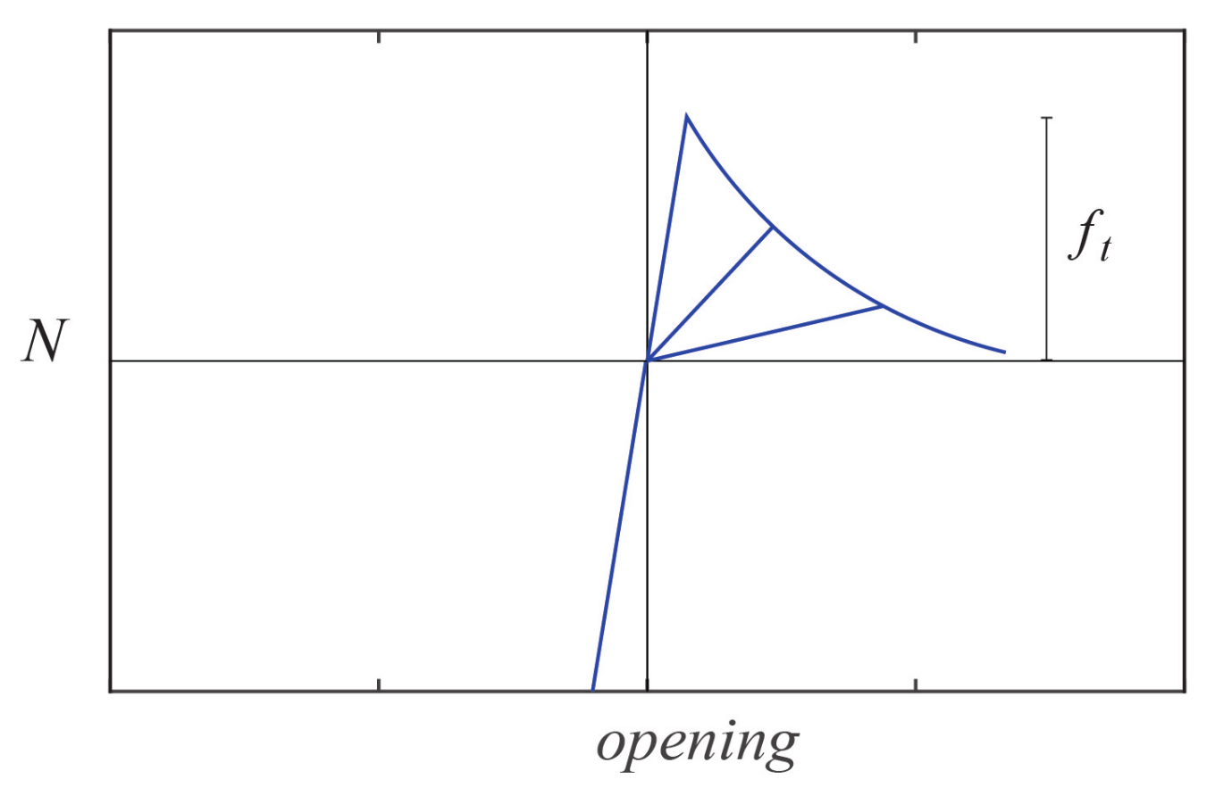
The strength of the wall-to-wall connection depends on the material properties and the level of interlocking in the corners, which also depends on the skills of the builders and modifications of the structure in its lifetime. We model masonry wall-to-wall connections in the equivalent frame model using a 1D material model that is linear elastic in compression with no crushing and with finite tensile strength with exponential softening [38], shown in Figure 3. The strength of the connections is calculated according to [69].
2.3. Modelling Assumptions for Timber Floors
In equivalent frame models, floors are usually modelled by elastic membrane elements with perfect connections between the floors and walls [14,27,28,49,67,68]. Such simplified assumptions are justified if the main goal is to describe the force redistribution and the floor-provided coupling of the response between different façades. However, if out-of-plane failure modes that span more than one floor are to be captured, the nonlinear in-plane response of the floor needs to be modelled. Since, in general, little distributed damage is observed on timber floors in post-earthquake surveys, concentrating the non-linearity in the connection between floors and walls is a reasonable approach [67]. The floor diaphragm is therefore modelled as linear elastic orthotropic membrane with a larger axial stiffness in the direction of the beams and a lower axial stiffness in the direction orthogonal to the beams [70,71]. To do this, estimates of timber floor properties are needed to describe the in-plane axial stiffness in both directions as well as the shear stiffness.
The diaphragm axial stiffness in the strong and weak direction of the timber floor is based on the timber stiffness both parallel and perpendicular to the grain. The diaphragm shear stiffness is computed according to the approach by Brignola et al. [70,71]. This shear stiffness, which is given in Equation (1), accounts for the (i) rigid rotation of the planks due to the slip of nails; (ii) flexural deformation of timber planks; and (iii) shear deformation of timber planks.
where is the shear correction factor (normally 5/6 for the rectangular cross-section), A is the area of a single plank section, l is the distance between the nail pairs on the opposite sides of a plank, is the nail stiffness per shear plane per fastener provided by codes [72], is the nails spacing, G is the shear modulus of timber planks, E is the flexural modulus parallel to the grains of timber planks, and I is the moment of inertia of the plank section. The nail stiffness is calculated according to EC 1995-1-1-2004 [72] using the equation:
where is the nail density in kg/m and d is the nail diameter in mm. The value of k is then in N/mm [72].
To model the increase in floor stiffness when an additional layer of timber planks is added as retrofit measure, the thickness and the equivalent shear stiffness are increased. The thickness of the retrofitted diaphragm corresponds to the thickness of the original planks plus the thickness of the new planks. The nails that are needed to fix the additional planks on the original planks increase the shear stiffness. Therefore, for the retrofitted configuration, we rewrite the equation as:
2.4. Modelling Assumptions for Wall-to-Diaphragm Connections
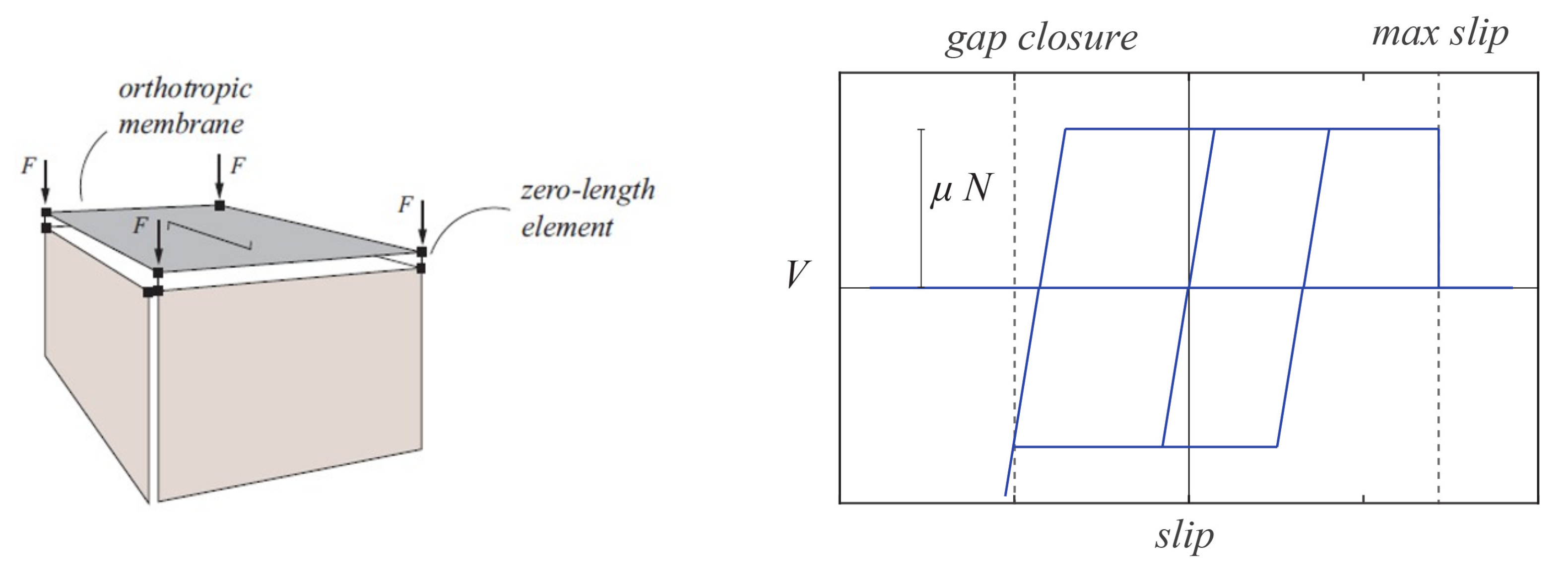
As outlined in the introduction, we model the limited force capacity of this connection explicitly for the unstrengthened wall-to-diaphragm connection, meaning when the force transfer from the floor to the wall relies on a Coulomb friction mechanism [73]. The values for the friction coefficient were derived from a series of friction tests between both timber and timber and timber and mortar [73]. As shown in Figure 4, we model this connection by a nonlinear spring, coupling axial and shear force. The model allows for loading in the positive direction through sliding (beam pulled off the support) and in the negative direction through pounding (beam pounding against the wall).
Wall-to-diaphragm connections are typically reinforced by anchoring the floor beam to the wall [40], which can make a rather stiff wall-to-diaphragm connection [74,75]. For the purpose of this study, these retrofitted connections are therefore assumed as infinitely stiff and strong and are modelled with the EqualDOF command in OpenSEES, which constructs a multi-point constraint between nodes [67]. In the future, additional simulations with a limited anchor capacity could be envisaged. First strength models for the anchor capacity in stone masonry and numerical simulations of the anchors were put forward by several groups [74,76,77].
2.5. Damping Model for Dynamic Analyses
Here, we conduct nonlinear time-history simulations using the equivalent frame model. Vanin et al. [78] showed that the overdamping that occurs with the classical Rayleigh damping model becomes especially relevant for out-of-plane behaviour. To avoid both the overdamping attributed to initial-stiffness proportional damping and the numerical problems stemming from tangential-stiffness proportional damping, we used the newly developed secant-stiffness proportional damping model in this study [78]. The secant-stiffness proportional damping model defines a correction term for the initial stiffness-matrix proportional damping in the classical Rayleigh damping matrix, thus approximating the secant-stiffness proportional damping model. This correction term is updated at each converged analysis step. The use of secant-stiffness proportional damping simulates out-of-plane rocking with acceptable accuracy when compared to the experimental data and classical rocking formulations, such as those of Housner et al. [79], and experimental evidence [78].
3. Case-Study Building
The case-study building is Building 1 of an experimental campaign by Magenes et al. comprising a full-scale unretrofitted stone masonry building (Pavia Building 1) and two retrofitted configurations of the same building (Pavia Building 2 and 3) [47,48,49]. The building was tested on the shake table at the EUCENTRE, Pavia, Italy. As outlined in the introduction, the two retrofitted configurations have already been successfully modelled by Penna et al. [68]. In this paper, we model Building 1, which developed significant in-plane deformations and then an out-of-plane failure mode. We directly base this model on the equivalent frame models of Buildings 2 and 3 by Penna et al., modified so the new equivalent frame model can capture the out-of-plane response developed by Building 1. In the following, we describe the unretrofitted building as well as the obtained experimental and numerical input data and the seismic record.
3.1. Experimental Campaign
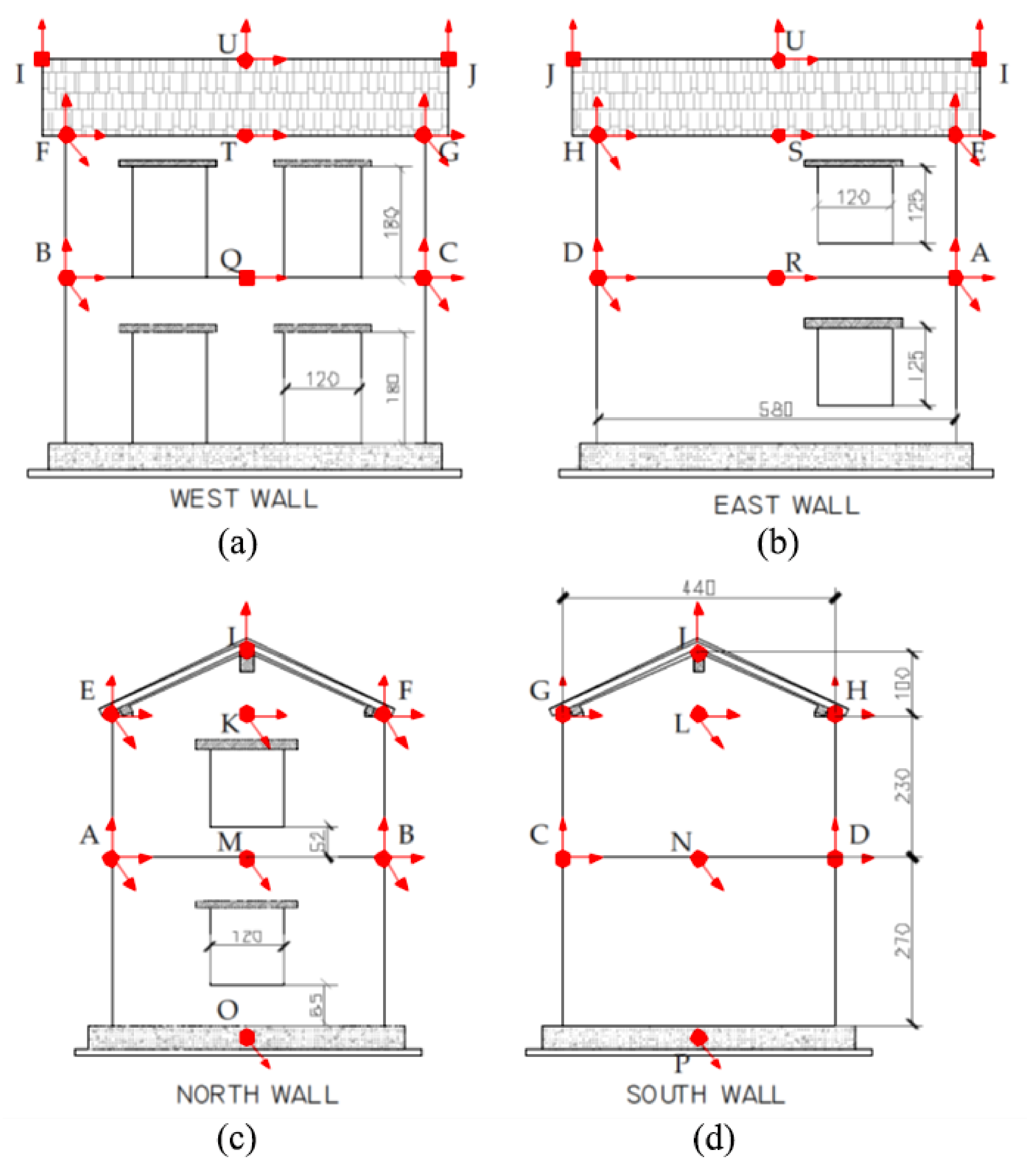
The Pavia Building 1 [47], shown in Figure 5, is representative of an existing stone masonry building without any aseismic detailing. The building was 5.8 m long and 4.4 m wide. It had two storeys and a roof; the total height from the base to the top of the gable was 6.0 m. The walls were 32–cm-thick double-leaf stone masonry, without throughstones except in the corners and in the vicinity of openings. Two leaves of undressed stones were simply built adjacent to each other with smaller stones and mortar filling the irregular gaps. The four facades had different opening layouts such that some rotation in the building was expected. It is therefore a suitable case study of the effects of the floor diaphragms and wall-to-diaphragm connections on the seismic response.
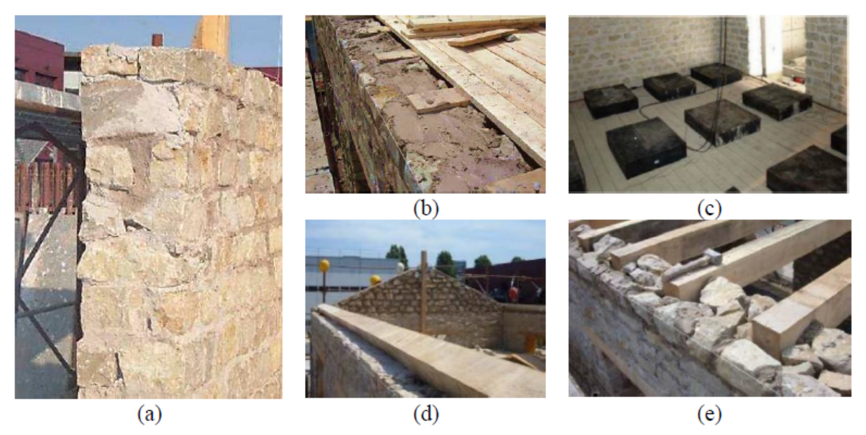
The floor was composed of timber beams that were 12 cm wide and 16 cm thick with planks that were 30 mm thick simply nailed on top of the beam [47]. The roof was composed of a 20 cm × 32 cm ridge beam, two 32 cm × 12 cm spreader beams and 8 cm × 12 cm purlins. The 30–mm-thick roof planks were again simply nailed on top of the purlins. The details of the masonry walls, floors and connections are shown in Figure 6. Additional masses were evenly distributed onto the floors, for a total amount of 3.2 tons.
3.2. Numerical Model
All three buildings had the same overall geometry, differing only with regard to the floor and roof details. The previous model of Buildings 2 and 3 [68] included a sensitivity study regarding the discretisation of the equivalent frame model. We built here on their work and use the “MOD” discretisation, which they concluded to be the most appropriate for capturing the force capacity and damage mechanism observed during testing. In the “MOD” discretisation, the height of the piers was equal to the height of the adjacent openings.
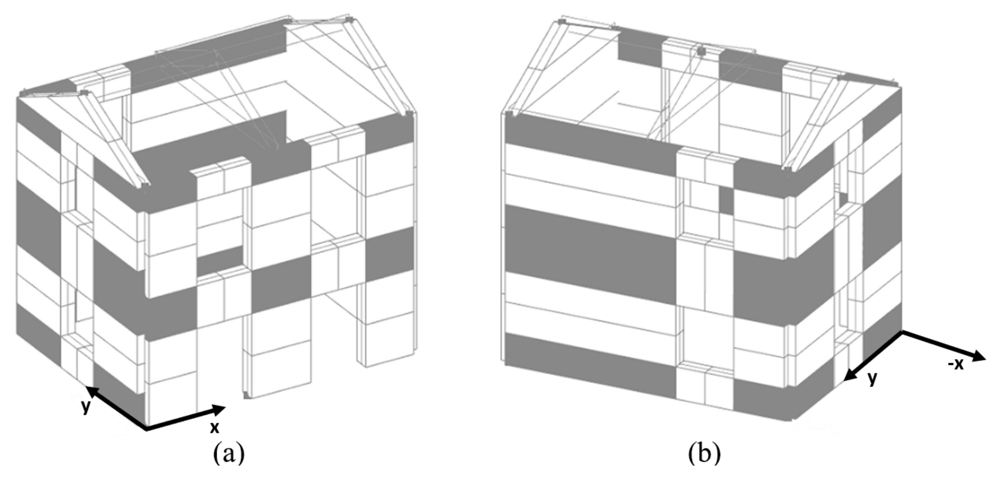
Our material parameters for masonry in the numerical model are based on those used in the equivalent frame models for Buildings 2 and 3 [68], which were analysed using the software Tremuri [27] with the macro-element by Penna et al. [28]. As outlined in Section 2, we used the macro-element by Vanin et al. [38], which builds the in-plane response on the macro-element by Penna et al. [28]. For this reason, the macro-element parameters were based on the values used in the original modelling of Buildings 2 and 3 [68]. The chosen set of material parameters for the macro-element simulating masonry piers and spandrels is shown in Table 1. For each model, the modal properties were calculated first and then the Rayleigh damping model parameters were computed such that the damping ratios at the first and sixth mode corresponded to the damping ratio of this model. We built upon the existing models by using the ability of the macro-element [38] to explicitly model the out-of-plane behaviour. As shown in Tomić et al. [37], when the out-of-plane behaviour is accounted for, the influence of non-linear connections can be highlighted. Therefore, unlike the Tremuri model where the floors were assumed to be perfectly connected to the walls and the stiffness was calibrated accordingly, here we explicitly model the non-linear connections to base the stiffness of the floor diaphragm on material properties and mechanical formulation. The OpenSEES Building 1 model is shown in Figure 7.
Floors and roofs were modelled as orthotropic membranes, with the parameters calibrated according to Brignola et al. [70,71]. The floor-wall connection was modelled using a frictional interface calibrated according to the experimental tests performed by Almeida et al. [73]. The floor parameters and floor-wall connection parameters are summarised in Table 2. and represent the membrane axial moduli in the strong and weak direction, respectively, and G represents the shear modulus of the membrane. The first row contains stiffness values that estimate the timber properties of Building 1. For evaluating the influence of the retrofitting strategies on the building response, a diaphragm is first modelled considering a retrofit of an additional layer of planks and nails. Then, the retrofitted floor-wall connection is modelled followed by the seismic performance of the building for both retrofitting techniques applied simultaneously.
3.3. Seismic Excitation
In the experimental campaign, Building 1 was subjected to the east-west component of the seismic record of the Montenegro 1979 earthquake at the Albatros station [47]. The record was scaled to nominal PGAs (Peak Ground Accelerations) between 0.05–0.40 g, and Building 1 was subjected to five runs of increasing intensities (Table 3). The actual applied PGAs were between 0.07–0.63 g. The numerical simulations used the actual applied ground motion as recorded during the test. To capture the damage evolution, we performed one long analysis that comprised all five runs. In between runs, we included zero ground acceleration records to again reach near zero building vibrations at the start of the next run.
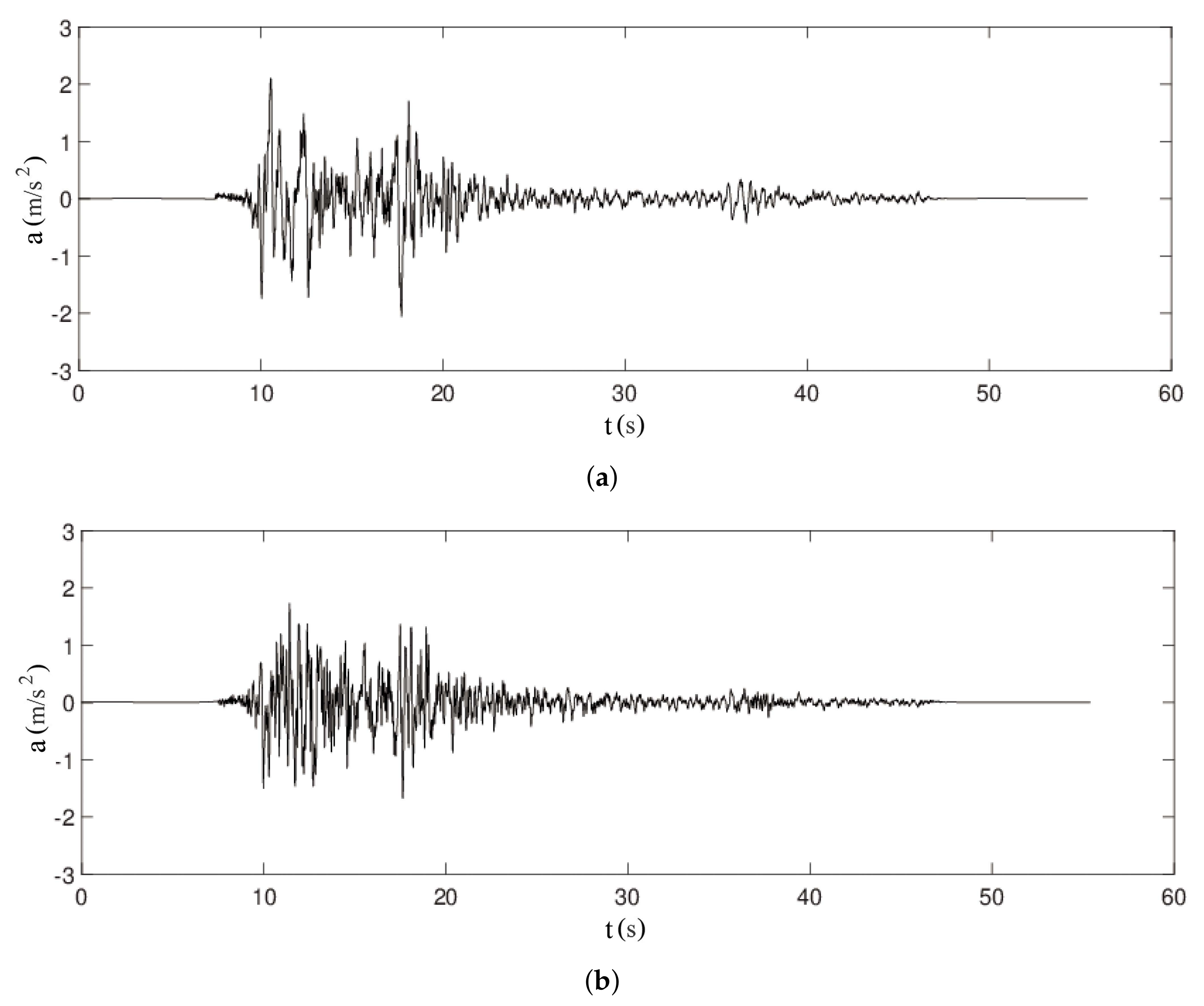
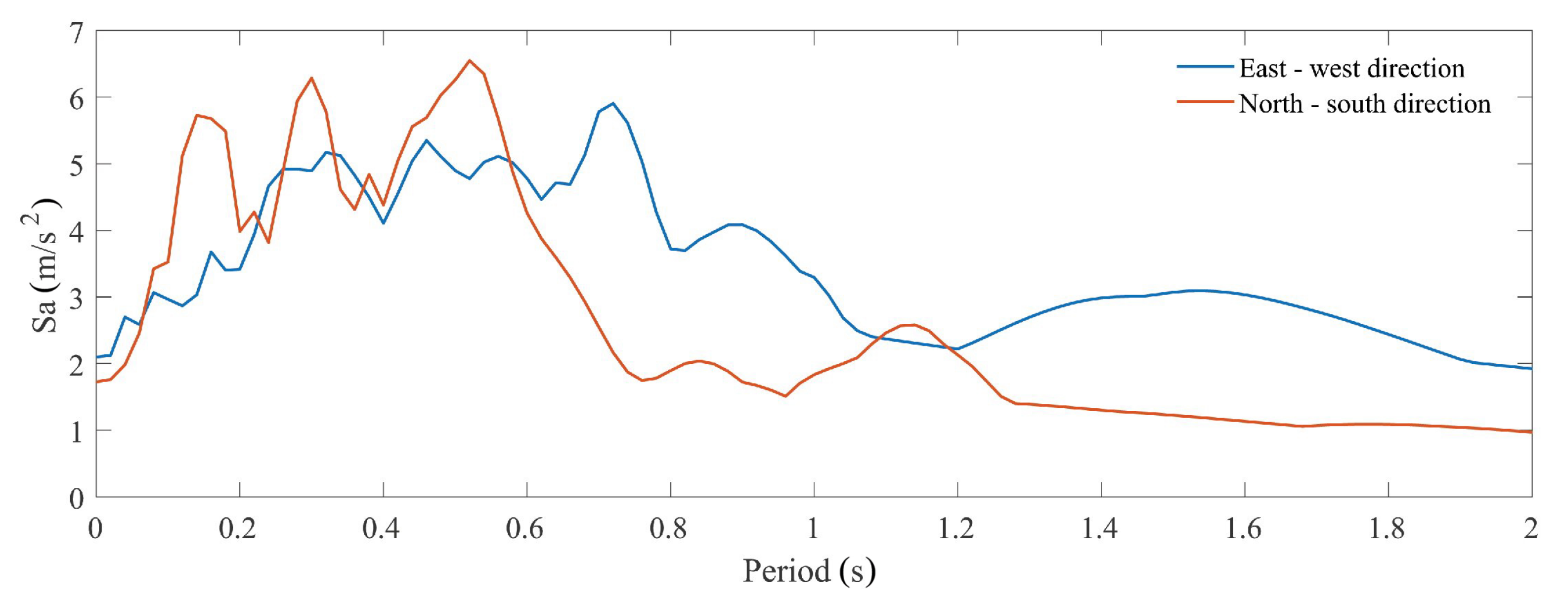
For the second part of the analyses where we studied the interplay of diaphragm- and connection-strengthening interventions, incremental dynamic analyses (IDAs) were performed. The applied ground motions comprised both horizontal components of the Montenegro 1979 earthquake at the Albatros station, with the east-west component applied in the x-direction and the north-south component in the y-direction. For these analyses, we used the record as downloaded from Engineering Strong Motion Database [80]. The acceleration records and the response spectra are shown in Figure 8 and Figure 9, respectively. More details on the IDAs are given in Section 4.2.
4. Numerical Results for the Case-Study Building
We started by validating the numerical model of the unretrofitted building against the experimental data from the uni-directional shake table-test with regard to displacement demands and damage mechanisms. We analysed the four configurations of the case study building, the original unretrofitted and three retrofitted configurations, with regard to the differences in floor diaphragm and wall-to-diaphragm connections. These analyses were performed using the bi-directional seismic excitation of the Montenegro 1979 record. The run time for running a single model IDA analysis, consisting of 12 dynamic analyses, was about 1 hour on an Intel Pentium i7 with 16 GB of RAM and a Nvidia Quadro P2000.
4.1. Model Validation
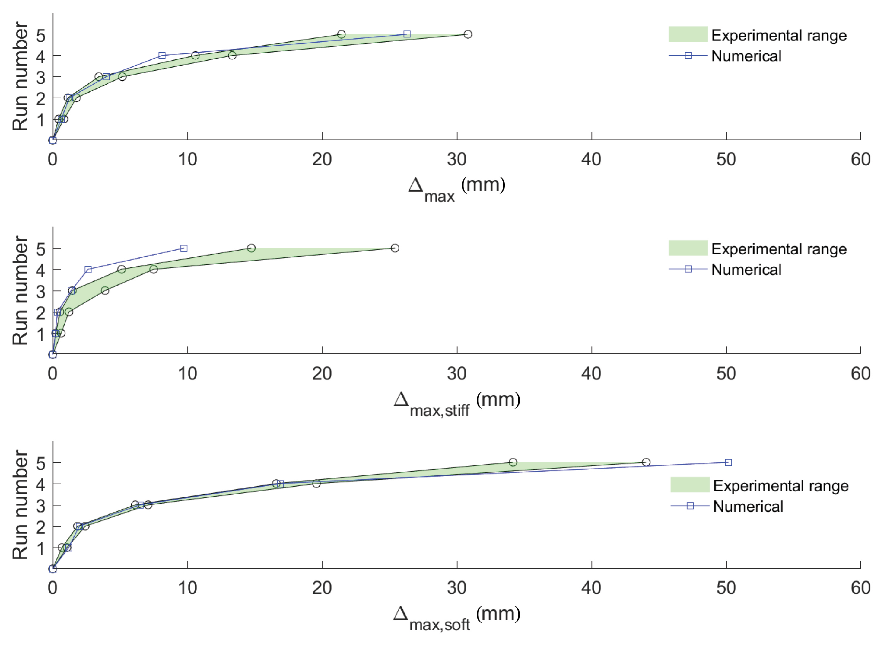
For each of the five runs, the experimental data set contained accelerations recorded at 22 positions on the building and its foundation. To derive the displacements, we double-integrated the signals and applied a band-pass filter before each integration. Because it was difficult to choose the single best set of corner frequencies for the band-pass filter, we chose several sets that all produced results that are in agreement with the video recording of the test [81]. The corner frequencies of the band-pass filter were judged reasonable if the maximum relative x-displacement between accelerometers F and T (Figure 5) was between 4–10 cm, which was the maximum sliding displacement estimated from the video of the test [81]. Based on this check, we chose two sets of corner frequencies (wide band: 0.5–450 Hz, narrow band: 1–40 Hz) and assume that the so-obtained displacements are the bounds of likely displacements. The numerical prediction was compared to the experimental results in terms of the average displacement of three measurements: (i) the 2nd storey, (ii) the stiff (east) facade of the 2nd storey, and (iii) the soft (west) facade of the 2nd storey. All displacements are in the x-direction.
The only model parameter that was calibrated was the damping ratio. To do this, we tested damping ratios between 1 and 5%, and the best fit was obtained for a damping ratio of 2.5%. As outlined in Section 2, we chose a secant-stiffness proportional damping model. Figure 10 compares the maximum displacement values per run. The predicted maximum values of the average displacement of the 2nd storey () lay within the bounds of the derived experimental values for almost all levels of excitation; the match is therefore very good. The model tended to underestimate the displacements of the stiff facade (), while the displacements of the soft facade () were well predicted, except for the last run, for which the model overestimated the displacement demand.
The out-of-plane displacements of the gables were not measured during the test, but they can be observed via recorded videos [81,82,83] and the mechanism that developed during the final run (nominal PGA of 0.4 g) is sketched in [48]: (i) The north facade containing the opening developed an out-of-plane mechanism that involved the 2nd storey and gable wall of the facade as well as the adjacent pier and spandrel of the 2nd storey of the west facade. This part of the building rotated around the bottom of the 2nd storey (line A-B in Figure 5); (ii) The out-of-plane mechanism of the south facade involved only the gable wall, i.e., the gable rotated around its base (line G-H in Figure 5). The numerical model replicated the dominant out-of-plane behaviour of both out-of-plane facades, as shown in Figure 11.
4.2. Modelling Retrofitting Interventions
Once the model of the unretrofitted configuration was validated, it was used to model the following unretrofitted and three retrofitted scenarios:
- Unretrofitted (diaphragm and wall-to-diaphragm connection unretrofitted): This corresponds to the configuration of Building 1.
- Diaphragm retrofitted: The diaphragm stiffness was increased to reflect the effect of an additional layer of planks (Table 2).
- Wall-to-diaphragm connections retrofitted: The wall-to-diaphragm connections were modelled as infinitely stiff and strong using equal DOF constraints.
- Diaphragm and wall-to-diaphragm connections retrofitted: The two individual retrofitting conditions were combined.
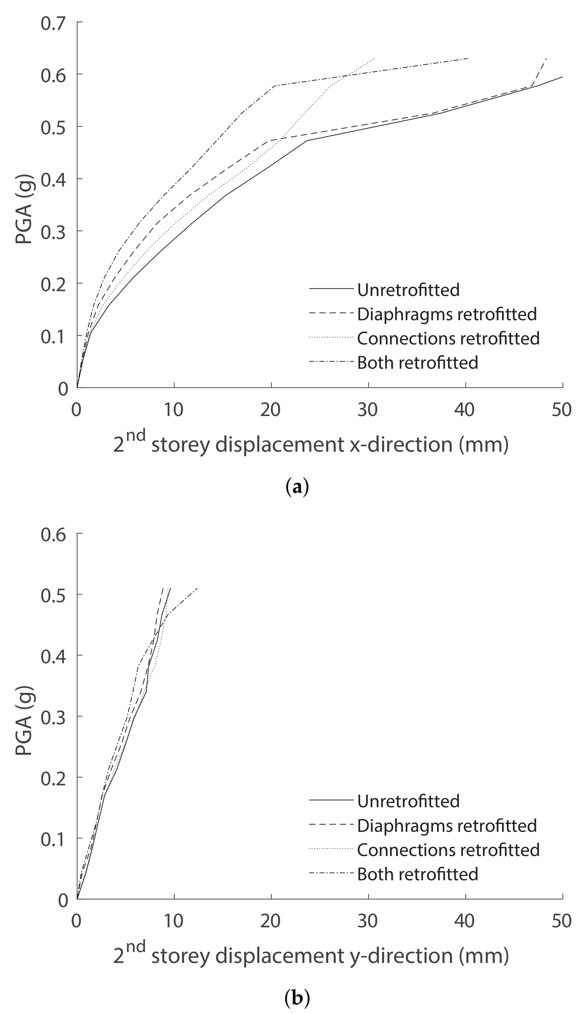
Each of the models was subjected to an IDA (Incremental Dynamic Analysis) using the two horizontal components of the Montenegro 1979 record [80] (see Section 3), with the east-west component in the x-direction and the north-south component in the y-direction. The record was scaled—for the east-west direction, the starting PGA of 0.0525 g was increased in increments of 0.0525 g until a PGA of 0.63 g was reached (the effective PGA applied in the final run of the shake table test [Table 3]). For the north-south direction, the starting PGA of 0.043 g was increased in increments of 0.043 g until a PGA of 0.516 g was reached. Figure 12 shows the IDA curves for the x- and y-direction. The IDA curves are plotted as PGA vs. the absolute maximum value of the mean 2nd storey displacement.
The IDA curves for the x-direction show that for PGA values below a threshold value (here 0.4725 g), retrofitting the diaphragm reduced the displacements, as the sliding displacements of the diaphragm-wall connections were still small. Therefore, the increased shear stiffness of the retrofitted diaphragm proves effective. However, when the PGA rose above the threshold value, the capacity of the wall-to-diaphragm connection became the weak link, and significant sliding displacements occurred between the floor and wall. Then, in the two models with unretrofitted wall-to-diaphragm connections, sliding occurred at those connections, which drastically increased the mean 2nd storey displacement to produce a kink in the PGA-displacement curve. This means that the force transferred by the diaphragm is limited by the wall-to-diaphragm connections, and therefore, the beneficial effect of retrofitting the diaphragm is reduced. In fact, for PGAs larger than 0.45 g, the mean 2nd storey displacement of the original unretrofitted configuration and the configuration with only the diaphragm retrofitted were almost equal. Conversely, models with retrofitted connections make use of the full stiffness of the diaphragm.
The difference in the y-direction was significantly lower. This was partly due to the lack of significant out-of-plane behaviour in the y-direction for any of the modelling approaches in comparison with the out-of-plane displacements of the gables in the x-direction. The reduced impact of the shear stiffness on the redistribution of the loads between the in-plane walls also lowered the overall difference in the y-direction.
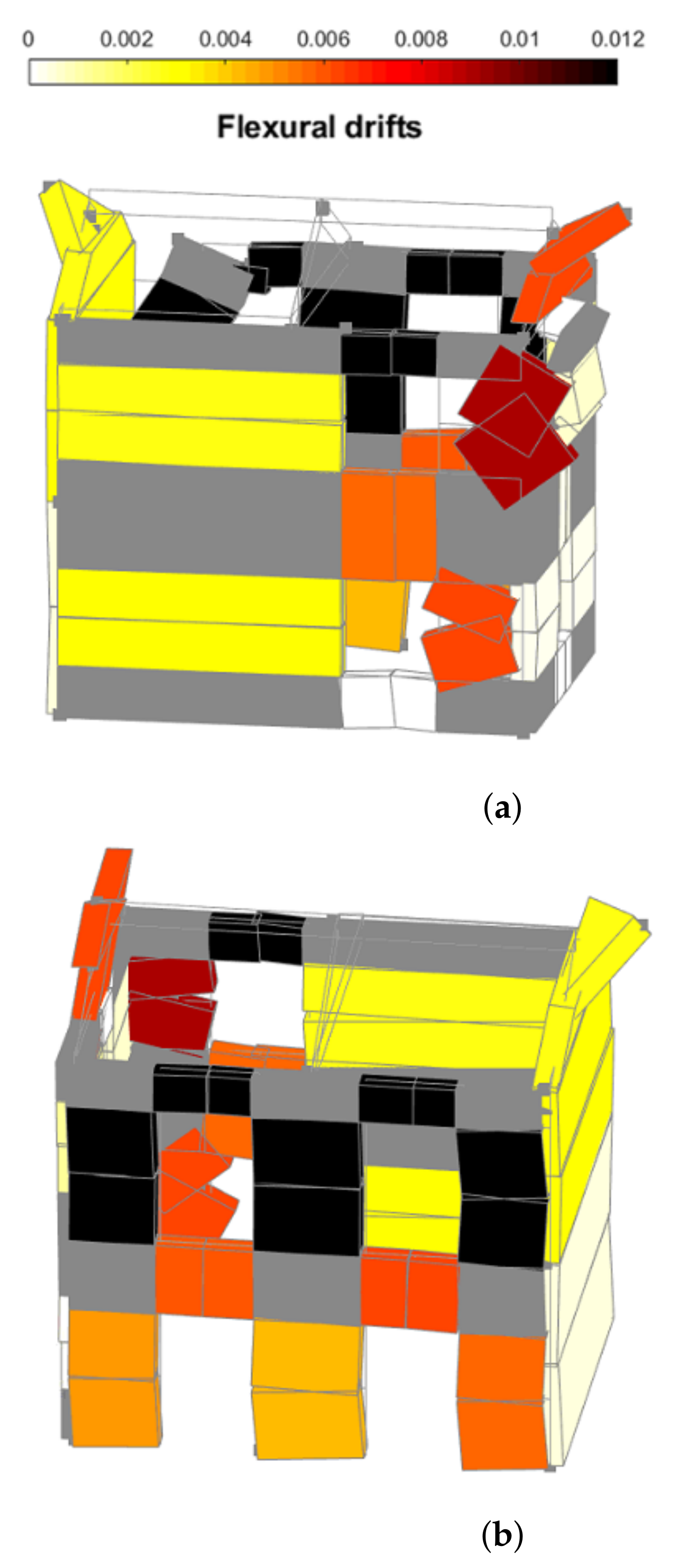
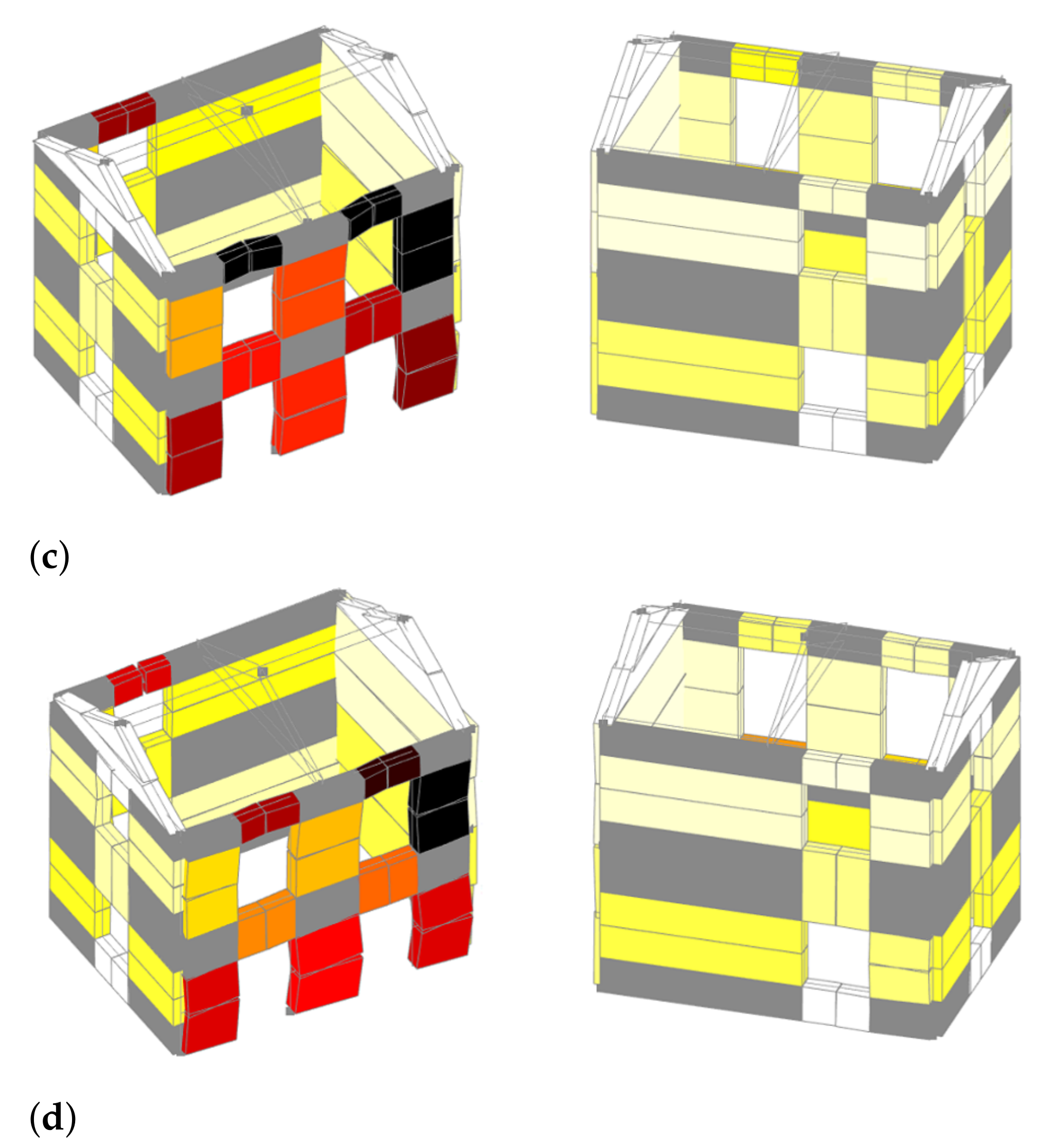
The effect of the retrofitting solutions was also visible when observing the deformed shapes, which are shown in Figure 13 for a PGA of 0.58 g. The unretrofitted and diaphragm-only retrofitted models showed a significant out-of-plane displacement of the gable walls. The in-plane deformation of the soft facade (west facade) was slightly lower for the diaphragm retrofitted model than for the unretrofitted model, but a larger effect was prevented by the limited force capacity of the wall-to-diaphragm connections. Otherwise, the two models with retrofitted connections did not show any significant out-of-plane displacements, which are successfully prevented by the rigid connections. The rigid connections fully exploit the beneficial effect of the increased shear stiffness of the retrofitted diaphragm, leading to lower displacements and drifts when compared to the model with only the connections retrofitted.
4.3. Force Demand on the Wall-to-Diaphragm Connections
The analyses showed that retrofitting wall-to-diaphragm connections significantly impacts the behaviour of the case-study building, shifting the failure mode from out-of-plane to in-plane. However, to ensure the behaviour as predicted by the model, the necessary pre-condition is that the wall-to-diaphragm connection must be reinforced by anchors able to sustain the force demand. The EqualDOF command, which was initially used to model the wall-to-diaphragm connections retrofitted by anchors (Section 2), did not provide the force transmitted by this connection. Therefore, to measure this force demand in another set of analyses, this connection was also modelled using very stiff elastic elements. The impact on the results was negligible, and the maximum tensile force demands on the wall-to-diaphragm connections for the example of PGA of 0.63 g are given in Table 4.
For the first storey, the largest tensile force demand of 20.58 kN/m was recorded for the anchors. This value was obtained by dividing the sum of the recorded tensile forces in the anchors with the length of the facade to obtain a value more practical for the design of the retrofitting intervention. For the second storey, the largest tensile force demand anchoring the roof to the wall was 7.56 kN/m. For the gable, the largest tensile force demand of 37.09 kN was recorded and reported here as a concentrated force, as a single anchor pair is assumed to anchor the ridge beam to the gable wall.
Ciocci et al. [75] tested the pull-out capacity of injection anchors in masonry of a similar typology to the case-study building. The anchor configurations each consisted of two horizontal anchors that failed at the cone. The test showed a direct relationship between the pull-out capacity and the overburden stress. For a very low overburden stress, such as the one acting on the roof-wall connection, the mean capacity of such a pair of anchors was approximately 30 kN; meaning that even for a very low overburden stress, the tested anchor design would achieve the assumed behaviour in the case-study building with a reasonable number of anchors per meter. Due to the possible high local concentration of force in the anchor pair, special attention should be paid to the anchorage of the ridge beam into the gable wall.
5. Conclusions
In this paper, we validated an equivalent frame model for unreinforced masonry buildings with unstrengthened timber floors and diaphragm-wall connections. This equivalent frame model completes the suite of models covering the full range of diaphragm and connection details found in unstrengthened and strengthened configurations of historical stone masonry buildings. Building configurations with strengthened floor diaphragms and wall-to-diaphragm connections had already been successfully modelled and validated by Penna et al. [68]. Modelling the unstrengthened configuration required three modifications: First, the new macro-element by Vanin et al. [38] captured in-plane and out-of-plane failure modes of piers and spandrels. Second, the wall-to-wall and wall-to-diaphragm connections were modelled with infinite stiffness but limited strength using nonlinear springs. Third, a new secant-damping model prevented the overdamping of rocking motions that is frequently observed for initial-stiffness proportional damping [78]. These changes allowed us to capture next-to-inelastic, in-plane deformations and large, nonlinear, out-of-plane displacements. The modelling approach was validated against the results of the Pavia Building 1 shake test [47].
In a second step, we investigated the influence of strengthening interventions on the global behaviour and local failure modes of the building under earthquake loading. The following modelling assumptions were made with regard to diaphragms and diaphragm-wall connections in their unstrengthened and strengthened configuration:
- In its unstrengthened configuration, the diaphragm consists of timber beams and a single layer of planks nailed to the timber beams. The diaphragm is modelled as an orthotropic elastic membrane. The properties of this membrane are determined according to Brignola et al. [70].
- The diaphragm is retrofitted by adding a layer of planks at a right angle to the first layer of planks. The increase in stiffness of the diaphragm is again calculated using the formulae provided in [70], with a slight modification to account for the deformation of the additional set of nails (Equation (3)).
- The wall-to-diaphragm connection in its unstrengthened configuration transfers loads only via friction. Representative friction coefficients were determined by Almeida et al. [73]. In finite element models of configurations with unstrengthened wall-to-diaphragm connections, the connection was modelled as rigid until the friction force was attained and sliding occurred.
- It was assumed that the wall-to-diaphragm connection was retrofitted by injection anchors that are relatively stiff until the peak force is attained. For this reason, they were modelled as infinitely rigid with infinite force capacity. Using the force capacities attained, it was computed how many anchors would be necessary to transfer the forces between the diaphragm and wall, which were recorded for the numerical model. Reasonable numbers were attained.
The effect of the two retrofit interventions (strengthening of floor diaphragms and of wall-to-diaphragm connections) was investigated by simulating virtual retrofit measures for Pavia Building 1. For this case-study building, strengthening the diaphragm alone only had an effect up to a threshold value of the PGA, where the capacity of the frictional wall-to-diaphragm connection was exceeded. For larger PGA levels, the seismic response of the building could only be improved if the wall-to-diaphragm connections were strengthened. Retrofitted wall-to-diaphragm connections increased the capacity because the failure mode changed from out-of-plane to in-plane. When the wall-to-diaphragm connections were retrofitted, also retrofitting the diaphragm improved the PGA values beyond the threshold value because this prevented sliding of the wall-to-diaphragm connections. Here, retrofitting the diaphragm led to smaller average peak displacements in comparison to the model where only the connections, but not the diaphragm, were retrofitted.
These observations lead to two conclusions: (i) When designing a retrofitting intervention, increasing the shear stiffness of a diaphragm can produce a more favourable response for lower PGA levels but will only negligibly affect the limit states closer to collapse when the wall-to-diaphragm connection becomes the weak link; and (ii) When modelling unreinforced masonry buildings using the equivalent frame approach, it is necessary to explicitly model the wall-to-diaphragm connection, as simplification to a perfect connection might lead to an unrealistic box-type behaviour. This is particularly important if the equivalent frame model should capture both global in-plane as well as local out-of-plane failure modes.
In addition to further validations of this modelling approach against large-scale experimental results, future work should address the nonlinear response of retrofitted wall-to-diaphragm connections and the non-linear response of diaphragms.
Author Contributions
Conceptualization, K.B. and F.V.; methodology, I.T.; software, F.V.; validation, I.T. and I.B.; formal analysis, I.T.; investigation, I.T.; resources, K.B.; data curation, I.T.; writing—original draft preparation, I.T.; writing—review and editing, K.B. and F.V.; visualization, I.T.; supervision, K.B.; project administration, K.B.; funding acquisition, K.B. All authors have read and agreed to the published version of the manuscript.
Funding
The project was supported by the Swiss National Science Foundation through grant 200021_175903/1: Equivalent frame models for the in-plane and out-of-plane response of unreinforced masonry building.
Institutional Review Board Statement
Not applicable.
Informed Consent Statement
Not applicable.
Data Availability Statement
The OpenSEES models used for producing the results presented in this paper as well as the data with results of the calibration procedure and IDAs are shared openly through the repository doi:10.5281/zenodo.4659149.
Acknowledgments
We would like to express our gratitude to Ilaria Senaldi (EUCENTRE, Pavia, Italy) and Andrea Penna (University of Pavia, Italy) for providing the data of the experimental campaign as well as the equivalent frame models of Building 2 and 3.
Conflicts of Interest
The authors declare no conflict of interest.
Abbreviations
The following abbreviations are used in this manuscript:
| DOF | Degree of freedom |
| PGA | Peak ground acceleration |
| IDA | Incremental dynamic analysis |
References
- Tomazevic, M. Earthquake-Resistant Design of Masonry Buildings; Imperial College Press: London, UK, 1999; Volume 1. [Google Scholar]
- D’Ayala, D.; Speranza, E. Definition of collapse mechanisms and seismic vulnerability of historic masonry buildings. Earthq. Spectra 2003, 19, 479–509. [Google Scholar] [CrossRef]
- Penna, A.; Morandi, P.; Rota, M.; Manzini, C.F.; da Porto, F.; Magenes, G. Performance of masonry buildings during the Emilia 2012 earthquake. Bull. Earthq. Eng. 2014, 12, 2255–2273. [Google Scholar] [CrossRef]
- Carocci, C.F. Small centres damaged by 2009 L’Aquila earthquake: On site analyses of historical masonry aggregates. Bull. Earthq. Eng. 2012, 10, 45–71. [Google Scholar] [CrossRef]
- Da Porto, F.; Munari, M.; Prota, A.; Modena, C. Analysis and repair of clustered buildings: Case study of a block in the historic city centre of L’Aquila (Central Italy). Constr. Build. Mater. 2013, 38, 1221–1237. [Google Scholar] [CrossRef]
- Lourenço, P.B. Computations on historic masonry structures. Prog. Struct. Eng. Mater. 2002, 4, 301–319. [Google Scholar] [CrossRef]
- Roca, P.; Cervera, M.; Gariup, G. Structural analysis of masonry historical constructions. Classical and advanced approaches. Arch. Comput. Methods Eng. 2010, 17, 299–325. [Google Scholar] [CrossRef] [Green Version]
- Bui, T.T.; Limam, A. Elventh International Conference on Computational Structures Technology; Civil-Comp Press: Stirlingshire, UK, 2012; p. 119. [Google Scholar] [CrossRef]
- Pulatsu, B.; Erdogmus, E.; Lourenço, P.B.; Lemos, J.V.; Tuncay, K. Simulation of the in-plane structural behavior of unreinforced masonry walls and buildings using DEM. In Structures; Elsevier: Amsterdam, The Netherlands, 2020; Volume 27, pp. 2274–2287. [Google Scholar]
- DeJong, M.J.; Belletti, B.; Hendriks, M.A.; Rots, J.G. Shell elements for sequentially linear analysis: Lateral failure of masonry structures. Eng. Struct. 2009, 31, 1382–1392. [Google Scholar] [CrossRef]
- Zhang, S.; Mousavi, S.M.T.; Richart, N.; Molinar, J.F.; Beyer, K. Micro-mechanical finite element modeling of diagonal compression test for historical stone masonry structure. Int. J. Solids Struct. 2017, 112, 122–132. [Google Scholar] [CrossRef]
- Lourenco, P.B.; Silva, L.C. Computational applications in masonry structures: From the meso-scale to the super-large/super-complex. Int. J. Multiscale Comput. Eng. 2020, 18. [Google Scholar] [CrossRef]
- Bracchi, S.; Rota, M.; Penna, A.; Magenes, G. Consideration of modelling uncertainties in the seismic assessment of masonry buildings by equivalent-frame approach. Bull. Earthq. Eng. 2015, 13, 3423–3448. [Google Scholar] [CrossRef]
- Quagliarini, E.; Maracchini, G.; Clementi, F. Uses and limits of the Equivalent Frame Model on existing unreinforced masonry buildings for assessing their seismic risk: A review. J. Build. Eng. 2017, 10, 166–182. [Google Scholar] [CrossRef]
- Parisi, F.; Augenti, N. Seismic capacity of irregular unreinforced masonry walls with openings. Earthq. Eng. Struct. Dyn. 2013, 42, 101–121. [Google Scholar] [CrossRef]
- Siano, R.; Sepe, V.; Camata, G.; Spacone, E.; Roca, P.; Pelà, L. Analysis of the performance in the linear field of equivalent-frame models for regular and irregular masonry walls. Eng. Struct. 2017, 145, 190–210. [Google Scholar] [CrossRef] [Green Version]
- Siano, R.; Roca, P.; Camata, G.; Pelà, L.; Sepe, V.; Spacone, E.; Petracca, M. Numerical investigation of non-linear equivalent-frame models for regular masonry walls. Eng. Struct. 2018, 173, 512–529. [Google Scholar] [CrossRef]
- Berti, M.; Salvatori, L.; Orlando, M.; Spinelli, P. Unreinforced masonry walls with irregular opening layouts: Reliability of equivalent-frame modelling for seismic vulnerability assessment. Bull. Earthq. Eng. 2017, 15, 1213–1239. [Google Scholar] [CrossRef]
- D’Altri, A.M.; Sarhosis, V.; Milani, G.; Rots, J.; Cattari, S.; Lagomarsino, S.; Sacco, E.; Tralli, A.; Castellazzi, G.; de Miranda, S. Modeling Strategies for the Computational Analysis of Unreinforced Masonry Structures: Review and Classification; Springer: Dordrecht, The Netherlands, 2020; Volume 27, pp. 1153–1185. [Google Scholar] [CrossRef]
- Magenes, G.; Fontana, A. Simplified non-linear seismic analysis of masonry buildings. In Proceedings of the British Masonry Society No. 8; British Masonry Society: London, UK, 1998; pp. 190–195. [Google Scholar]
- Kappos, A.J.; Penelis, G.G.; Drakopoulos, C.G. Evaluation of simplified models for lateral load analysis of unreinforced masonry buildings. J. Struct. Eng. 2002, 128, 890–897. [Google Scholar] [CrossRef]
- Roca, P.; Molins, C.; Marí, A.R. Strength capacity of masonry wall structures by the equivalent frame method. J. Struct. Eng. 2005, 131, 1601–1610. [Google Scholar] [CrossRef]
- Pasticier, L.; Amadio, C.; Fragiacomo, M. Non-linear seismic analysis and vulnerability evaluation of a masonry building by means of the SAP2000 V. 10 code. Earthq. Eng. Struct. Dyn. 2008, 37, 467–485. [Google Scholar] [CrossRef]
- Belmouden, Y.; Lestuzzi, P. An equivalent frame model for seismic analysis of masonry and reinforced concrete buildings. Constr. Build. Mater. 2009, 23, 40–53. [Google Scholar] [CrossRef]
- Rizzano, G.; Sabatino, R. An equivalent frame model for the seismic analysis of masnory structures. In Proceedings of the 8th Congresso de Sismologia e Engenharia Sismica, Aveiro, Portugal, 20–23 October 2010. [Google Scholar]
- Caliò, I.; Marletta, M.; Pantò, B. A new discrete element model for the evaluation of the seismic behaviour of unreinforced masonry buildings. Eng. Struct. 2012, 40, 327–338. [Google Scholar] [CrossRef]
- Lagomarsino, S.; Penna, A.; Galasco, A.; Cattari, S. TREMURI program: An equivalent frame model for the nonlinear seismic analysis of masonry buildings. Eng. Struct. 2013, 56, 1787–1799. [Google Scholar] [CrossRef]
- Penna, A.; Lagomarsino, S.; Galasco, A. A nonlinear macroelement model for the seismic analysis of masonry buildings. Earthq. Eng. Struct. Dyn. 2014, 43, 159–179. [Google Scholar] [CrossRef]
- Addessi, D.; Mastrandrea, A.; Sacco, E. An equilibrated macro-element for nonlinear analysis of masonry structures. Eng. Struct. 2014, 70, 82–93. [Google Scholar] [CrossRef]
- Raka, E.; Spacone, E.; Sepe, V.; Camata, G. Advanced frame element for seismic analysis of masonry structures: Model formulation and validation. Earthq. Eng. Struct. Dyn. 2015, 44, 2489–2506. [Google Scholar] [CrossRef]
- Peruch, M.; Spacone, E.; Camata, G. Nonlinear analysis of masonry structures using fiber-section line elements. Earthq. Eng. Struct. Dyn. 2019, 48, 1345–1364. [Google Scholar] [CrossRef]
- Yousefi, B.; Soltani, M. An Equivalent Fiber Frame Model for Nonlinear Analysis of Masonry Structures. Int. J. Archit. Herit. 2021, 15, 644–668. [Google Scholar] [CrossRef]
- Grande, E.; Imbimbo, M.; Sacco, E. Finite element analysis of masonry panels strengthened with FRPs. Compos. Part B Eng. 2013, 45, 1296–1309. [Google Scholar] [CrossRef]
- Tondelli, M.; Rota, M.; Penna, A.; Magenes, G. Evaluation of uncertainties in the seismic assessment of existing masonry buildings. J. Earthq. Eng. 2012, 16, 36–64. [Google Scholar] [CrossRef]
- Rota, M.; Penna, A.; Magenes, G. A framework for the seismic assessment of existing masonry buildings accounting for different sources of uncertainty. Earthq. Eng. Struct. Dyn. 2014, 43, 1045–1066. [Google Scholar] [CrossRef]
- De Falco, A.; Guidetti, G.; Mori, M.; Sevieri, G. Model uncertainties in seismic analysis of existing masonry buildings: The Equivalent-Frame Model within the Structural Element Models approach. In Proceedings of the XVII Convengo Anidis, Pistoia, Italy, 17–21 September 2017; Pisa University Press: Pisa, Italy, 2017; pp. 63–73. [Google Scholar]
- Tomić, I.; Vanin, F.; Beyer, K. Uncertainties in the Seismic Assessment of Historical Masonry Buildings. Appl. Sci. 2021, 11, 2280. [Google Scholar] [CrossRef]
- Vanin, F.; Penna, A.; Beyer, K. A three-dimensional macroelement for modelling the in-plane and out-of-plane response of masonry walls. Earthq. Eng. Struct. Dyn. 2020, 49, 1365–1387. [Google Scholar] [CrossRef]
- Lagomarsino, S.; Cattari, S. PERPETUATE guidelines for seismic performance-based assessment of cultural heritage masonry structures. Bull. Earthq. Eng. 2015, 13, 13–47. [Google Scholar] [CrossRef]
- Solarino, F.; Oliveira, D.V.; Giresini, L. Wall-to-horizontal diaphragm connections in historical buildings: A state-of-the-art review. Eng. Struct. 2019, 199, 109559. [Google Scholar] [CrossRef]
- Tomaževič, M.; Weiss, P.; Velechovsky, T. The influence of rigidity of floors on the seismic behaviour of old stone-masonry buildings. Eur. Earthq. Eng. 1991, 3, 28–41. [Google Scholar]
- Benedetti, D.; Carydis, P.; Pezzoli, P. Shaking table tests on 24 simple masonry buildings. Earthq. Eng. Struct. Dyn. 1998, 27, 67–90. [Google Scholar] [CrossRef]
- Dolce, M.; Ponzo, F.; Goretti, A.; Moroni, C.; Giordano, F.; De Canio, G.; Marnetto, R. 3d dynamic tests on 2/3 scale masonry buildings retrofitted with different systems. In Proceedings of the 14th World Conference on Earthquake Engineering, Beijing, China, 12–17 October 2008; Volume 1217. [Google Scholar]
- Dolce, M.; Ponzo, F.C.; Di Croce, M.; Moroni, C.; Giordano, F.; Nigro, D.; Marnetto, R. Experimental assessment of the CAM and DIS-CAM systems for the seismic upgrading of monumental masonry buildings. In Proceedings of the PROHITECH, Rome, Italy, 21–24 June 2009; Volume 9. [Google Scholar]
- Bothara, J.K.; Dhakal, R.P.; Mander, J.B. Seismic performance of an unreinforced masonry building: An experimental investigation. Earthq. Eng. Struct. Dyn. 2010, 39, 45–68. [Google Scholar] [CrossRef]
- Mazzon, N.; Chavez, C.M.; Valluzzi, M.R.; Casarin, F.; Modena, C. Shaking Table Tests on Multi-Leaf Stone Masonry Structures: Analysis of Stiffness Decay. Structural Analysis of Historic Constructions. In Advanced Materials Research; Trans Tech Publications Ltd.: Bach, Switzerland, 2010; Volume 133, pp. 647–652. [Google Scholar] [CrossRef]
- Magenes, G.; Penna, A.; Galasco, A. A full-scale shaking table test on a two-storey stone masonry building. In Proceedings of the 14th European Conference on Earthquake Engineering, Ohrid, North Macedonia, 30 August–3 September 2010. [Google Scholar]
- Magenes, G.; Penna, A.; Senaldi, I.E.; Rota, M.; Galasco, A. Shaking table test of a strengthened full-scale stone masonry building with flexible diaphragms. Int. J. Archit. Herit. 2014, 8, 349–375. [Google Scholar] [CrossRef]
- Senaldi, I.; Magenes, G.; Penna, A.; Galasco, A.; Rota, M. The effect of stiffened floor and roof diaphragms on the experimental seismic response of a full-scale unreinforced stone masonry building. J. Earthq. Eng. 2014, 18, 407–443. [Google Scholar] [CrossRef]
- Costa, A.A.; Arêde, A.; Costa, A.C.; Penna, A.; Costa, A. Out-of-plane behaviour of a full scale stone masonry façade. Part 2: Shaking table tests. Earthq. Eng. Struct. Dyn. 2013, 42, 2097–2111. [Google Scholar] [CrossRef]
- Vintzileou, E.; Mouzakis, C.; Adami, C.E.; Karapitta, L. Seismic behavior of three-leaf stone masonry buildings before and after interventions: Shaking table tests on a two-storey masonry model. Bull. Earthq. Eng. 2015, 13, 3107–3133. [Google Scholar] [CrossRef]
- Pitilakis, D.; Iliou, K.; Karatzetzou, A. Shaking table tests on a stone masonry building: Modeling and identification of dynamic properties including soil-foundation-structure interaction. Int. J. Archit. Herit. 2018, 12, 1019–1037. [Google Scholar] [CrossRef]
- Mouzakis, C.; Adami, C.E.; Karapitta, L.; Vintzileou, E. Seismic behaviour of timber-laced stone masonry buildings before and after interventions: Shaking table tests on a two-storey masonry model. Bull. Earthq. Eng. 2018, 16, 803–829. [Google Scholar] [CrossRef]
- Kallioras, S.; Guerrini, G.; Tomassetti, U.; Marchesi, B.; Penna, A.; Graziotti, F.; Magenes, G. Experimental seismic performance of a full-scale unreinforced clay-masonry building with flexible timber diaphragms. Eng. Struct. 2018, 161, 231–249. [Google Scholar] [CrossRef]
- Guerrini, G.; Senaldi, I.; Graziotti, F.; Magenes, G.; Beyer, K.; Penna, A. Shake-Table Test of a Strengthened Stone Masonry Building Aggregate with Flexible Diaphragms. Int. J. Archit. Herit. 2019, 13, 1078–1097. [Google Scholar] [CrossRef]
- Kim, S.C.; White, D.W. Nonlinear analysis of a one-story low-rise masonry building with a flexible diaphragm subjected to seismic excitation. Eng. Struct. 2004, 26, 2053–2067. [Google Scholar] [CrossRef]
- Betti, M.; Galano, L.; Vignoli, A. Comparative analysis on the seismic behaviour of unreinforced masonry buildings with flexible diaphragms. Eng. Struct. 2014, 61, 195–208. [Google Scholar] [CrossRef]
- Nakamura, Y.; Derakhshan, H.; Magenes, G.; Griffith, M.C. Influence of diaphragm flexibility on seismic response of unreinforced masonry buildings. J. Earthq. Eng. 2017, 21, 935–960. [Google Scholar] [CrossRef]
- Nakamura, Y.; Derakhshan, H.; Griffith, M.C.; Magenes, G.; Sheikh, A.H. Applicability of nonlinear static procedures for low-rise unreinforced masonry buildings with flexible diaphragms. Eng. Struct. 2017, 137, 1–18. [Google Scholar] [CrossRef] [Green Version]
- Gattesco, N.; Macorini, L.; Benussi, F. Retrofit of wooden floors for the seismic adjustment of historical buildings with high reversible techniques. Seismic Engineering in Italy. In Proceedings of the XII National Conference, Pisa, Italy, 25–27 October 2007; pp. 10–14. [Google Scholar]
- Scotta, R.; Trutalli, D.; Marchi, L.; Pozza, L. Effects of in-plane strengthening of timber floors in the seismic response of existing masonry buildings. In Proceedings of the World Conference on Timber Engineering (WCTE), Vienna, Austria, 22–25 August 2016; pp. 22–25. [Google Scholar]
- Scotta, R.; Trutalli, D.; Marchi, L.; Pozza, L.; Mirra, M. Seismic response of masonry buildings with alternative techniques for in-plane strengthening of timber floors. In Proceedings of the XII International Conference on Structural Repair and Rehabilitation (CINPAR), Porto, Portugal, 1 July 2017; pp. 26–29. [Google Scholar]
- Mirra, M. Analisi Parametriche Dinamiche non Lineari Degli Effetti Dell’ Irrigidimento di Solai in Legno in Edifici in Muratura Ordinaria. 2017. Available online: http://tesi.cab.unipd.it/59766/ (accessed on 12 April 2021).
- Trutalli, D.; Marchi, L.; Scotta, R.; Pozza, L. Dynamic simulation of an irregular masonry building with different rehabilitation methods applied to timber floors. In Proceedings of the 6th ECCOMAS Thematic Conference (COMPDYN 2017), Rhodes Island, Greece, 12–14 June 2017; pp. 15–17. [Google Scholar]
- McKenna, F.; Fenves, G.; Scott, M.; Jeremic, B. Open System for Earthquake Engineering Simulation (OpenSees); University of California: Berkeley, CA, USA, 2000; Available online: http://opensees.berkeley.edu (accessed on 1 February 2021).
- Ortega, J.; Vasconcelos, G.; Rodrigues, H.; Correia, M. Assessment of the influence of horizontal diaphragms on the seismic performance of vernacular buildings. Bull. Earthq. Eng. 2018, 16, 3871–3904. [Google Scholar] [CrossRef]
- Vanin, F.; Penna, A.; Beyer, K. Equivalent-frame modeling of two shaking table tests of masonry buildings accounting for their out-of-plane response. Front. Built Environ. 2020, 6, 42. [Google Scholar] [CrossRef] [Green Version]
- Penna, A.; Senaldi, I.E.; Galasco, A.; Magenes, G. Numerical simulation of shaking table tests on full-scale stone masonry buildings. Int. J. Archit. Herit. 2016, 10, 146–163. [Google Scholar] [CrossRef]
- POLIMI. Critical Review of Methodologies and Tools for Assessment of Failure Mechanisms and Interventions, Deliverable 3.3, Workpackage 3: Damage Based Selection of Technologies; Technical Report; NIKER Project: Padova, Italy, 2010. [Google Scholar]
- Brignola, A.; Podesta, S.; Pampanin, S. In-Plane Stiffness of Wooden Floor; Technical Report; Department of Civil and Natural Resources Engineering, University of Canterbury: Christchurch, New Zealand, 2008. [Google Scholar]
- Brignola, A.; Pampanin, S.; Podestà, S. Experimental evaluation of the in-plane stiffness of timber diaphragms. Earthq. Spectra 2012, 28, 1687–1709. [Google Scholar] [CrossRef] [Green Version]
- EC 1995-1-1-2004. Eurocode 5—Design of Timber Structures—Part 1-1: General Rules and Rules for Buildings; Technical Report; EN 1995-1-1: Bruxelles, Belgium, 2004. [Google Scholar]
- Almeida, J.P.; Beyer, K.; Brunner, R.; Wenk, T. Characterization of mortar–timber and timber–timber cyclic friction in timber floor connections of masonry buildings. Mater. Struct. 2020, 53, 51. [Google Scholar] [CrossRef]
- Moreira, S.M.T.; Oliveira, D.V.; Ramos, L.F.; Fernandes, R.; Guerreiro, J.; Lourenço, P.B. Experimental study on the seismic behavior of masonry wall-to-floor connections. In Proceedings of the 15th World Conference on Earthquake Engineering, Sociedade Portuguesa de Engenharia Sísmica (SPES), Lisbon, Portugal, 24–28 September 2012. [Google Scholar]
- Ciocci, M.P.; Van Nimwegen, S.; Askari, A.; Vanin, F.; Lourenço, P.; Beyer, K. Experimental investigation on the behaviour of injection anchors in rubble stone masonry. 2021; in preparation. [Google Scholar]
- Muñoz, R.; Lourenço, P.B.; Moreira, S. Experimental results on mechanical behaviour of metal anchors in historic stone masonry. Constr. Build. Mater. 2018, 163, 643–655. [Google Scholar] [CrossRef]
- Contrafatto, L.; Cosenza, R. Prediction of the pull-out strength of chemical anchors in natural stone. Frat. Integrità Strutt. 2014, 8, 196–208. [Google Scholar] [CrossRef] [Green Version]
- Vanin, F.; Beyer, K. Equivalent damping ratio for a macroelement modelling the out-of-plane response of masonry walls. 2021; in preparation. [Google Scholar]
- Housner, G.W. The behavior of inverted pendulum structures during earthquakes. Bull. Seismol. Soc. Am. 1963, 53, 403–417. [Google Scholar]
- Luzi, L.; Lanzano, G.; Felicetta, C.; D’Amico, M.C.; Russo, E.; Sgobba, S.; Pacor, F.; ORFEUS Working Group 5. Engineering Strong Motion Database (ESM) (Version 2.0); Technical Report; Istituto Nazionale di Geofisica e Vulcanologia (INGV): Rome, Italy, 2020. [Google Scholar] [CrossRef]
- EUCENTRE. PROVINO 1 0.40g 20090801 Telecamera 01. 2009. Available online: https://youtu.be/SspfD-nHCso?list=PL52352538BE37F38E (accessed on 2 April 2021).
- EUCENTRE. PROVINO 1 0.40g 20090801 Telecamera 03. 2009. Available online: https://youtu.be/egYnpB1FlK0?list=PL52352538BE37F38E (accessed on 2 April 2021).
- EUCENTRE. PROVINO 1 0.40g 20090801 Vista Multipla. 2009. Available online: https://youtu.be/7BFuXzrAbG0?list=PL52352538BE37F38E (accessed on 2 April 2021).
Figure 1.
Examples of out-of-plane damage patterns from L’Aquila 2009 earthquake: (a) Out-of-plane mechanism in long walls. (b) Global overturning of external walls. (c) Overturning due to the lack of anchorage between walls and horizontal diaphragms. (d) Corner out-of-plane mechanism [66]. (Sources: Dr. Javier Ortega, Prof. Hugo Rodrigues)

Figure 2.
Macro-element by Vanin et al. [38]: deformation modes.
Figure 2.
Macro-element by Vanin et al. [38]: deformation modes.

Figure 3.
Equivalent frame model of wall-to-wall interface [67].
Figure 3.
Equivalent frame model of wall-to-wall interface [67].

Figure 4.
Equivalent frame model of wall-to-diaphragm connection [38].
Figure 4.
Equivalent frame model of wall-to-diaphragm connection [38].

Figure 5.
Drawings of Pavia Building 1 with the positions of accelerometers: (a) West wall. (b) East wall. (c) North wall. (d) South wall [47].
Figure 5.
Drawings of Pavia Building 1 with the positions of accelerometers: (a) West wall. (b) East wall. (c) North wall. (d) South wall [47].

Figure 6.
Building 1 details: (a) masonry wall. (b,c) timber floor. (d,e) timber roof [47,48,49,68].

Figure 7.
OpenSEES model of Pavia Building 1: (a) View from the northwest corner. (b) View from the northeast corner.
Figure 7.
OpenSEES model of Pavia Building 1: (a) View from the northwest corner. (b) View from the northeast corner.

Figure 8.
Processed acceleration time-histories of the Montenegro 1979 earthquake at the Albatros station: (a) east-west direction. (b) north-south direction [80].
Figure 8.
Processed acceleration time-histories of the Montenegro 1979 earthquake at the Albatros station: (a) east-west direction. (b) north-south direction [80].

Figure 9.
Acceleration response spectra of the Montenegro 1979 earthquake at the Albatros station for 5% damping ratio [80].
Figure 9.
Acceleration response spectra of the Montenegro 1979 earthquake at the Albatros station for 5% damping ratio [80].

Figure 10.
Comparison of experimental and numerical maximum displacements at each run.

Figure 11.
Out-of-plane behaviour (magnification factor ×10): (a) North facade-out-of-plane displacement involving the 2nd storey piers and the gable. (b) South facade-out-of-plane displacement involving only the gable.
Figure 11.
Out-of-plane behaviour (magnification factor ×10): (a) North facade-out-of-plane displacement involving the 2nd storey piers and the gable. (b) South facade-out-of-plane displacement involving only the gable.

Figure 12.
IDA curves for the four configurations in terms of PGA vs. the absolute maximum values of average 2nd storey displacement: (a) in the x-direction (b) in the y-direction.
Figure 12.
IDA curves for the four configurations in terms of PGA vs. the absolute maximum values of average 2nd storey displacement: (a) in the x-direction (b) in the y-direction.

Figure 13.
Deformed shapes and maximum element drifts in flexure and shear (magnification factor ×10): (a) Unretrofitted. (b) Diaphragms retrofitted. (c) Connections retrofitted. (d) Both retrofitted.
Figure 13.
Deformed shapes and maximum element drifts in flexure and shear (magnification factor ×10): (a) Unretrofitted. (b) Diaphragms retrofitted. (c) Connections retrofitted. (d) Both retrofitted.


Table 1.
Pavia Building 1: Material parameters assumed for masonry elements [68].
Table 1.
Pavia Building 1: Material parameters assumed for masonry elements [68].
| E (MPa) | G (MPa) | (kg/m) | (MPa) | (MPa) | |
|---|---|---|---|---|---|
| 1900 | 300 | 2200 | 4.50 | 0.175 | 0.20 |
Table 2.
Pavia Building 1: Material parameters of diaphragms and the wall-to-diaphragm connections.
| (GPa) | (GPa) | G (MPa) | t (m) | ||
|---|---|---|---|---|---|
| Unretrofitted | 10 | 0.5 | 10.3 | 0.03 | 1.0 |
| Diaphragms retrofitted | 10 | 0.5 | 19.6 | 0.06 | 1.0 |
| Wall-to-diaphragm connections retrofitted | 10 | 0.5 | 10.3 | 0.03 | fixed |
| Diaphragms and connections retrofitted | 10 | 0.5 | 19.6 | 0.06 | fixed |
Table 3.
Building 1: Summary of shake-table runs [47].
Table 3.
Building 1: Summary of shake-table runs [47].
| Test Run | Nominal PGA (g) | Actual PGA (g) |
|---|---|---|
| 1 | 0.05 | 0.07 |
| 2 | 0.10 | 0.14 |
| 3 | 0.20 | 0.31 |
| 4 | 0.30 | 0.50 |
| 5 | 0.40 | 0.63 |
Table 4.
Maximum tensile force demands on the anchors of the first storey, second storey, and gable of the model with connections retrofitted for the PGA of 0.63 g.
Table 4.
Maximum tensile force demands on the anchors of the first storey, second storey, and gable of the model with connections retrofitted for the PGA of 0.63 g.
| Position | Unit | Maximum Tensile Force |
|---|---|---|
| First floor | (kN/m) | 20.58 |
| Second floor | (kN/m) | 7.56 |
| Gable | (kN) | 37.09 |
Publisher’s Note: MDPI stays neutral with regard to jurisdictional claims in published maps and institutional affiliations. |
© 2021 by the authors. Licensee MDPI, Basel, Switzerland. This article is an open access article distributed under the terms and conditions of the Creative Commons Attribution (CC BY) license (https://creativecommons.org/licenses/by/4.0/).
Share and Cite
MDPI and ACS Style
Tomić, I.; Vanin, F.; Božulić, I.; Beyer, K. Numerical Simulation of Unreinforced Masonry Buildings with Timber Diaphragms. Buildings 2021, 11, 205. https://0-doi-org.brum.beds.ac.uk/10.3390/buildings11050205
AMA Style
Tomić I, Vanin F, Božulić I, Beyer K. Numerical Simulation of Unreinforced Masonry Buildings with Timber Diaphragms. Buildings. 2021; 11(5):205. https://0-doi-org.brum.beds.ac.uk/10.3390/buildings11050205
Chicago/Turabian StyleTomić, Igor, Francesco Vanin, Ivana Božulić, and Katrin Beyer. 2021. "Numerical Simulation of Unreinforced Masonry Buildings with Timber Diaphragms" Buildings 11, no. 5: 205. https://0-doi-org.brum.beds.ac.uk/10.3390/buildings11050205
Note that from the first issue of 2016, this journal uses article numbers instead of page numbers. See further details here.