
Comparison of Novel Seismic Protection Devices to Attenuate the Earthquake Induced Energy


Department of Civil Engineering, Gaziantep University, Gaziantep 27310, Turkey
*
Author to whom correspondence should be addressed.
Actuators 2021, 10(4), 73; https://0-doi-org.brum.beds.ac.uk/10.3390/act10040073
Submission received: 12 February 2021
/
Revised: 23 March 2021
/
Accepted: 5 April 2021
/
Published: 7 April 2021
(This article belongs to the Special Issue Piezoelectric and Electrostrictive Materials in Mechatronics, Precision Engineering and Vibration Control)
Abstract
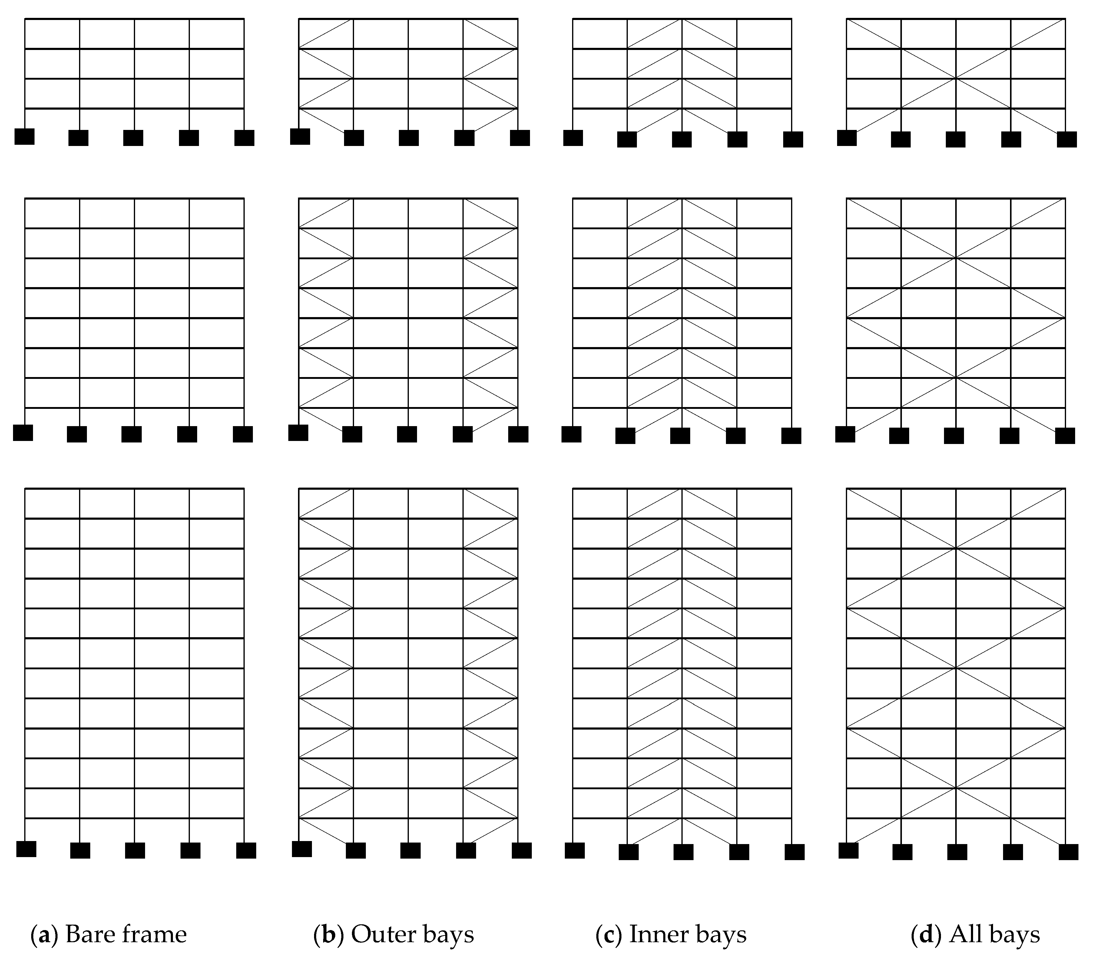
:This study addresses an alternative use of viscous dampers (VDs) associated with buckling restrained braces (BRBs) as innovative seismic protection devices. For this purpose, 4-, 8- and 12-story steel bare frames were designed with 6.5 m equal span length and 4 m story height. Thereafter, they were seismically improved by mounting the VDs and BRBs in three patterns, namely outer bays, inner bays, and all bays over the frame heights. The structures were modeled using SAP 2000 software and evaluated by the nonlinear time history analyses subjected to the six natural ground motions. The seismic responses of the structures were investigated for the lateral displacement, interstory drift, absolute acceleration, maximum base shear, and time history of roof displacement. The results clearly indicated that the VDs and BRBs reduced seismic demands significantly compared to the bare frame. Moreover, the all-bay pattern performed better than the others.
1. Introduction
Recent earthquake regulations in the world have promoted the structural design with sufficient ductility in earthquake-prone zones. Thus, the ductile design of structures has become the main goal of engineers to dissipate earthquake-induced energy without permanent damage or overall collapse. Earthquake forces generate stresses that need to be resisted by the frames in the buildings. When a structure undergoes strong ground motions, the conventional frames assume substantial lateral deformations so that structural and non-structural damages occur, compromising the structural integrity [1,2]. Specifically, shear failure occurs in a brittle manner, in which the column cannot continue to support the overall structure by energy dissipation, eventually leading to the collapse of the overall structure. Therefore, shear failure must be avoided in seismic design, and flexure–shear failure should remain under control because its ductility is worse than that of flexure failure [3]. Steel braces are integrated within the frames to prevent such failures in the steel structures [4,5,6,7]. Even though they seem to improve the lateral stiffness of the structures, steel braces have very limited ductility under cyclic tension and compression. After buckling in the concentrically braced frames, they have unsymmetrical hysteresis behavior associated with substantial strength degradation, thus being unable to dissipate the earthquake-induced energy [8,9]. With the advances in engineering technology, the conventional concentrically braced systems have been replaced by more innovative remedies. In recent years, diagrid structures began to be favored by architects and engineers because diagrid structural systems can provide more effective flexural and shear stiffness. The loads mainly resisted through the axial deformation of diagonal members, which makes the lateral deformation smaller. Despite the fact that diagrid structures attract significant attention owing to their unique shape, there are few detailed studies on it because the forces acting on the corresponding nodes are not very clear yet [10,11,12]. Buckling restrained braces (BRBs) have been developed to overcome buckling of the traditional braces and used in seismic protection [13,14,15]. Similarly, viscous dampers (VDs) have been utilized as a passive energy dissipating device for seismic protection of the structures. Both BRBs and VDs are capable of controlling the deformations developed in steel frames by dissipating the energy or increasing the stiffness [16,17,18,19,20].
BRBs are designed so that no buckling occurs on the bracing provided by sufficient lateral support. In contrast to the conventional braces, they exhibit more stable and symmetrical hysteretic behavior under cyclic compression and tension generated by earthquakes. Because of such superior properties, BRBs have been the subject of various studies in the literature [21,22,23]. For example, Lin et al. [21] evaluated the seismic performance of eccentrically braced frames and buckling restrained braced frames in comparison with that of ordinary moment-resisting frames. Deulkar et al. [22] explored the effects of BRB with varying length and core area on the design of five-story steel frames. Both of the variables studied seemed to be quite effective on the type of the braces. In the study of Di Sarno and Elnashai [23], the seismic performances of special concentrically braced frame, buckling restrained braced frame, and mega braced frame were investigated. Recently, Jamkhaneh et al. [24] and Hosseinzadeh and Mohebi [25] modified ordinary BRBs to enhance the characteristics by virtue of which instability of the core is minimized, whereas the energy dissipation capacity is maximized. Fahaminia and Zahrai [26] utilized the buckling restrained knee braces with the shape memory alloy core to reduce the residual deformations of the frames.
The use of VDs in the seismic protection of the structures relies on a general approach in decreasing the negative effects of earthquakes. Its primary function is to reduce the structural response by dissipating the energy within the dampers, thus significantly decreasing the potential damage in the framing system during an earthquake [27,28]. Conventional use of VDs as a seismic protection device was investigated by means of experiments and numerical simulations. However, as engineers have often employed them in the seismic design of buildings, the studies on the viscous dampers were concentrated on more specific subjects such as damper positions, damper properties, intensity of ground motions, optimization for cost efficiency, and using them in tall buildings [29,30,31,32,33,34]. For example, SaiChethan et al. [29] carried out a numerical assessment of a twenty-story reinforced concrete building. The results confirmed that a significant reduction in the responses such as displacements would be possible with the introduction of fluid VDs. Prasad and Mazumder [30] investigated the seismic response of a set of steel buildings with and without VDs installed in the inner bay for the energy dissipation. VDs were reported to reduce the displacements, which in turn decreased the amount of steel needed for the overall stability. The study conducted by Balkanlou et al. [31] demonstrated that the structure with dampers could be designed optimally to justify the cost spent for the use of dampers. Using VDs to mitigate the pounding of the adjacent buildings was the subject of Milanchian and Hosseini’s research [34]. The buildings were interconnected by VDs to provide vertical seismic isolation. Silvestri et al. [33] proposed a five-step procedure for the design of VDs to achieve target levels of performances. De Demonico et al. [35] gave energy-based perspectives to interpret the seismic performance in terms of the dissipated energy by the VDs out of the total earthquake-induced energy.
Previous studies on the BRBs and VDs have focused on their uses in the form of split X, inverted V, concentric, etc. by generally overlooking their position within the frames. As mentioned above, BRBs or VDs were generally installed within the inner bays of the model frames. Moreover, the comparative assessment of them under similar conditions has not taken adequate attention. In order to justify the benefit of using BRBs and VDs in seismic protection, more research studies on the modeling approach of such systems seem to be necessary. Considering this fact, a comparative study on the use of VDs and BRBs installed within the outer bays, inner bays or all bays of the steel structures is presented in this paper. For this, the contributions of the BRBs and VDs in improving the seismic performance of the structures were examined by means of the nonlinear time history analysis under six ground motions.
2. Details of Steel Frames, Modeling and Analysis
In this parametric study, a set of three different frames was employed to investigate the seismic protection capability of BRBs and VDs. For this purpose, 4, 8, and 12-story bare structures were designed as steel moment-resisting frames (MRFs) in accordance with Eurocode-3 and Eurocode-8 [36,37]. The story height and bay width of the frames were equal to 4 and 6.5 m, respectively. The bare structures have columns of HEA sections and beams of IPE sections. The fundamental periods of 4, 8, and 12-story frames were obtained as 0.64, 1.15, and 1.54 s, respectively. Figure 1 presents the elevation views of bare frames. Moreover, the placement of the BRBs and VDs throughout the each frame elevation is given in Figure 1.
The gravity loading on the floor system is considered as the additional dead loads of 2 kN/m2 and live loads of 3 kN/m2. The yield stress and the post-yield stiffness ratio of the steel material are assumed to be equal to 235 MPa and 0.03, respectively [38,39]. The lumped plasticity approach was followed for the nonlinear behavior of the frames. Therefore, the nonlinearity considered in the numerical models of the beams and columns were restricted by the plastic hinges assigned at the end of the frame members as described in FEMA-356 [40]. Mass-and-stiffness proportional damping was also taken into account in the analysis with a 5% damping ratio. A series of nonlinear time-history analyses have been performed using SAP 2000 [41] via direct integration method with the P-Delta effect included. P-delta effect was accounted for by using a ghost column. The ghost column was made of a vertical column of truss members horizontally slaved to the frame at each level. The gravity loads for the leaner columns tributary to the analyzed frame, one-half of the gravity loads for the entire structure, were applied to the ghost column at the appropriate floor.
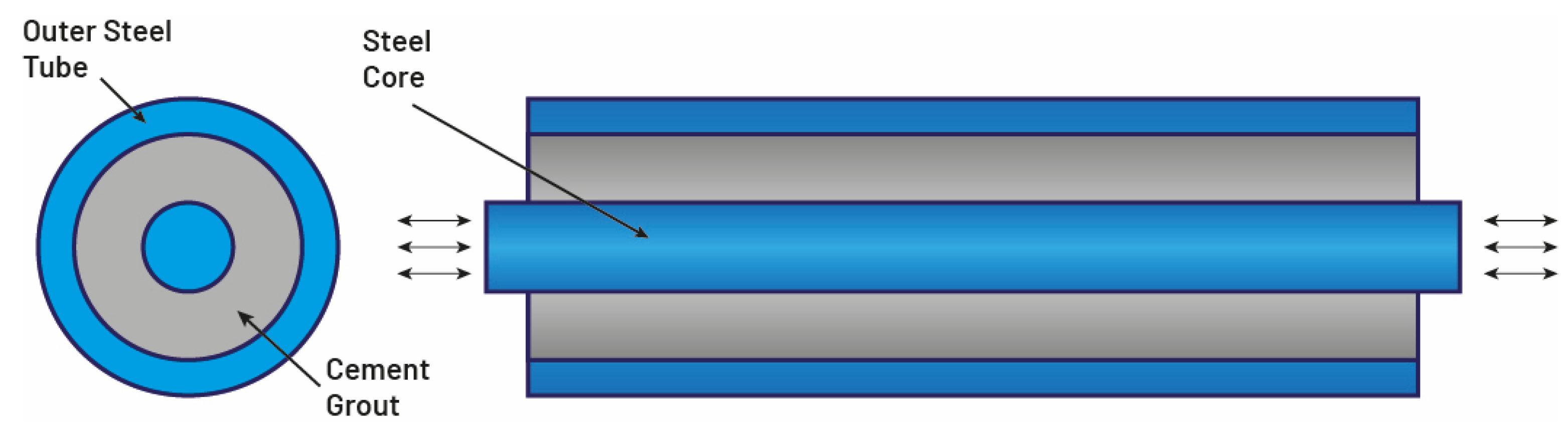
A detailed view of buckling restrained brace (BRB) section used in this study is given in Figure 2 [5]. The structural elements under the earthquake load have been ensured to remain within the total load core area to which they are exposed. The non-prismatic axial rigidity equations are considered to be elastic and post-elastic as k and k2, respectively [5].
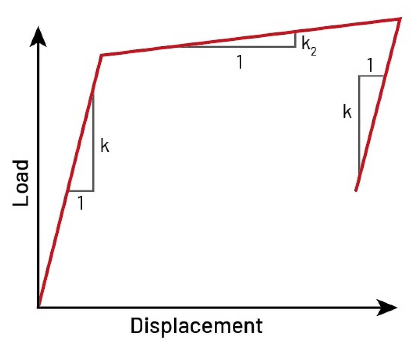
where A is the total cross-sectional area, E is the modulus of elasticity, is the length of beam member, α is the ratio of the decreased cross-sectional area to the whole area, β is the ratio of the length of the decreased core to the whole length, and is the deformation after yielding. In the nonlinear analyses, non-buckling bracing with a uniaxial plasticity property (see Figure 3) was modeled using a Multilinear plastic (MLP) link element in SAP 2000. Thus, MLP link creates an element that is linearly elastic up to yield after that the plastic region can be multilinear to include strain hardening. The effective stiffness assigned to the MLP link element was 30 kN/mm and a 3% strain hardening was considered.
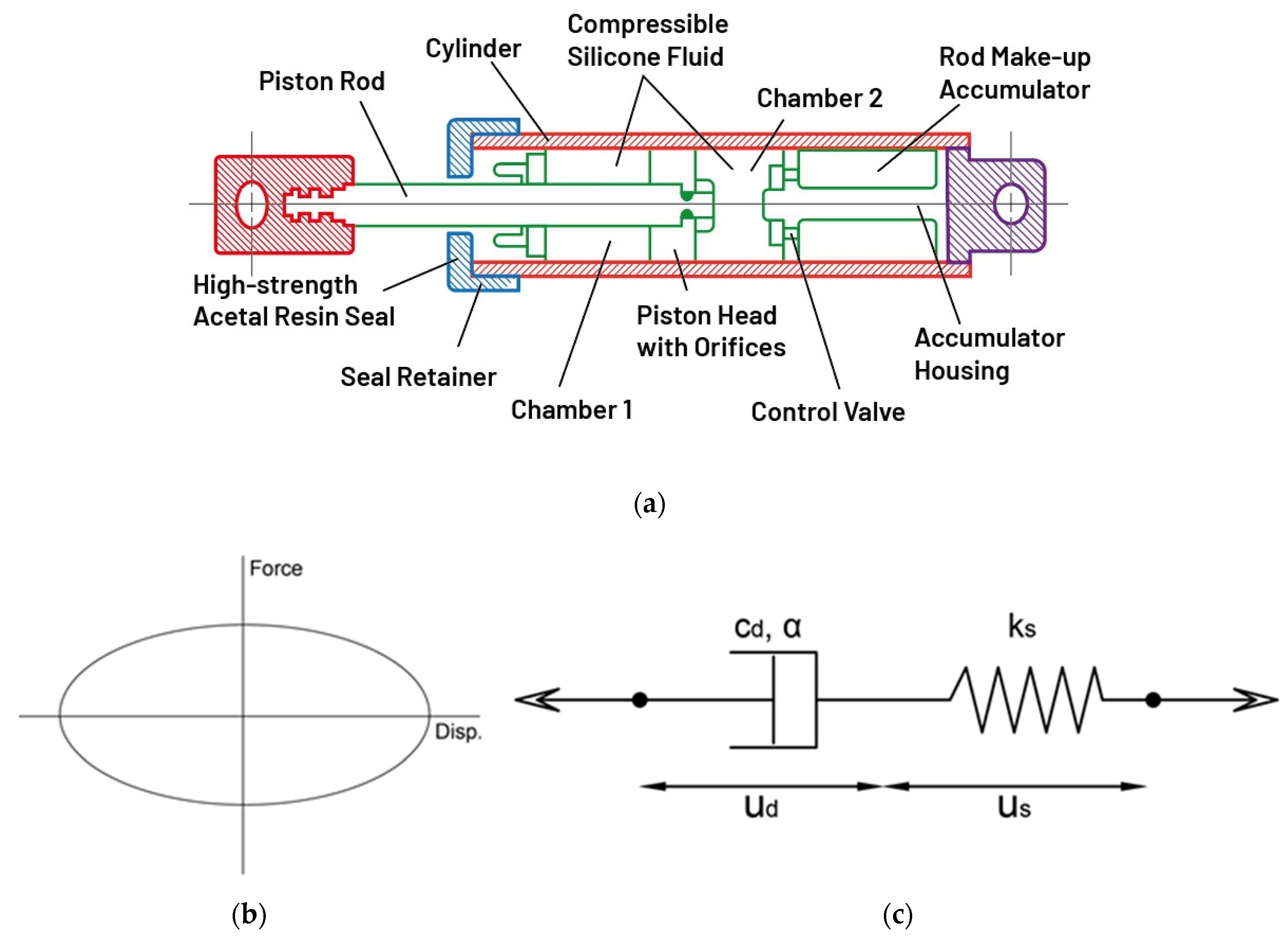
Another seismic protection system used in the current study is the viscous dampers (VDs). Such devices were originally developed for military applications and were later used for various applications that contribute to shock and vibration isolation such as energy-absorbing buffers, channel lock buffers, and offshore oil pillar suspension. Liquid VDs work on the principle of the flow of viscous liquid through the holes as seen in Figure 4a [30]. The VDs typically consist of a perforated piston head located in a cylinder filled with a highly viscous liquid. When the piston head moves into the liquid, the energy is distributed by directing the liquid into the damper. The fluid in the cylinder is virtually incompressible, and when the damper is subjected to a compression force, the volume of fluid in the cylinder decreases as a result of the piston rod region movement. A reduction in volume results in restoring force.
The general force–velocity relationship of nonlinear viscous models (Figure 4b) can be expressed mathematically by Equation (4), where Cd is the damping coefficient, α is the velocity exponent, ud is the dashpot displacement, and sgn represents the signum function. Thus the peak force Fd0 of a viscous damper is obtained as in Equation (5) under a harmonic displacement excitation of ud(t) = ud0sin(ωt),
where ud0 and ω are the peak displacement amplitude and the circular frequency of the sinusoidal excitation, respectively. The value of α characterizes the viscous material and, in turn, the behavior of the viscous damper. With α = 1, the device is called linearly viscous damper, while dampers with α > 1 have not been seen often in practical applications. For seismic design applications of frame buildings, the capability of limiting the damper force output under high-velocity pulses is often desirable. Therefore, for seismic applications, α is often selected such that α < 1 [30,42].
The Maxwell model has been found to represent well both the axial stiffness and frequency dependency of a viscous damper under dynamic loading [43,44,45]. The hysteretic behavior of VD described by spring and dashpot in series as Maxwell model (see Figure 4c) was analytically modeled in the study of Akcelyan et al. [46]. The force Fd at the nonlinear dashpot and spring (Fs) are equal; therefore, the constitutive rules within a Maxwell model can be written as in Equations (6)–(8). in which um, ud, and us are the total, dashpot, and spring displacements, respectively (see Figure 4c). The constitutive equation that describes the force and total velocity relation within a Maxwell model can be obtained if Equations (6) and (7) are substituted into Equation (8). For a nonlinear viscous damper, this equation is achieved as in Equation (9).
In accordance with the previous studies [30,33,46] the hysteretic behavior of VD described by the spring and dashpot in series was analytically modeled by using a nonlinear link element (i.e., damper) in SAP 2000. Therefore, the damper used in this analysis was a Taylor damper device with reference no RT50DH50 having the properties of the VD as the damper coefficient of 310 kNs/m, damper exponent of 0.52, stiffness of 30 kN/mm, and weight of 42 kg [30].
The frames were considered to be located in a very seismically active area and they were evaluated by using various ground motions extracted from the PEER [47] strong motion database with the following characteristics: the rupture distance (Rrup) is lower than 8.5 km, magnitude of the earthquake (Mw) is between 6.54 and 7.62, and Peak ground acceleration (PGA) is higher than 0.4 g. The properties of the six earthquake records, namely Cape, Gazlı, Northridge, Hills, Chi-Chi, and Tabas are given in Table 1. Moreover, they were scaled based on ASCE 7-10 [48]. The frames with and without BRBs and VDs were examined by means of the nonlinear time history analysis under the given earthquakes.
3. Verification of Analytical Models
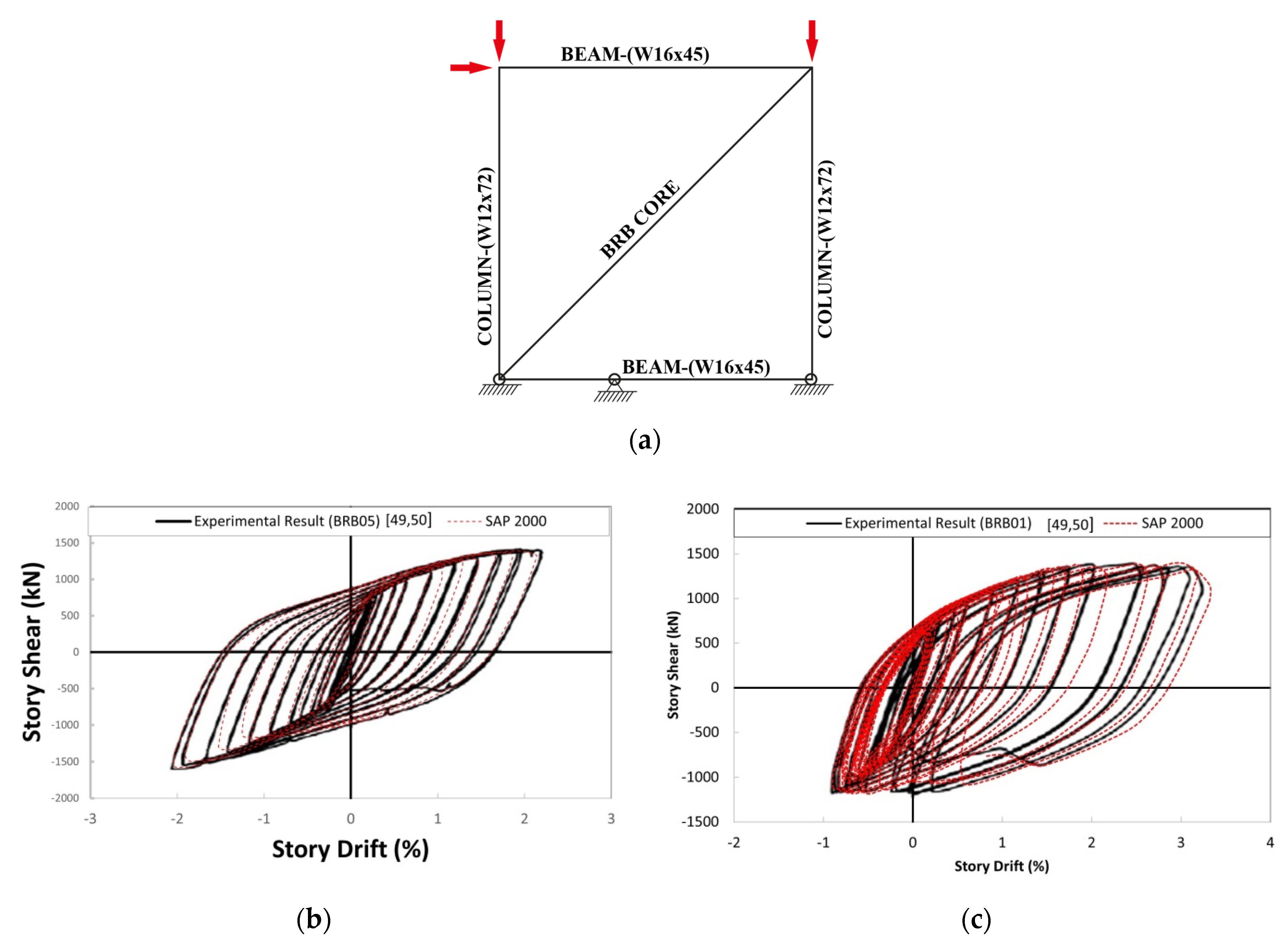
In this section, the SAP 2000 model is verified through the related experimental results. For this, the studies of Palmer et al. [49] and Christopulos [50] were utilized. They conducted the experimental work to address the performance of BRB connections in realistic framing systems and to develop a design methodology that ensures the ductility of BRB frame systems. The test program included the full-scale, single-bay, single-story planar BRB frames with the geometry of 3.68 m column spacing and story height as shown in Figure 5 [50]. The structural sections were used for the beams (W16 × 45) and columns (W12 × 72). The BRBs had a total length of 3.6 m, a 19 × 162 mm rectangular core plate with a length of 2.34 m, and a 250 × 250 × 6 mm steel tube restrainer casing with infill grout. A constant axial force of 780 kN was applied to both columns, which simulated gravity load from upper stories and limited column uplift. The experimental results are presented in Figure 5 as the story-shear force vs. drift response to represent the hysteretic behaviors of the frames with BRB05 and BRB01, respectively. Similarly, the numerical modeling of the frames with the aforementioned properties was performed through SAP 2000 in line with the experimental program. The results obtained from SAP 2000 are also presented in Figure 5. Comparisons between the experimental results with those obtained from the SAP 2000 models indicated that the developed SAP 2000 models were able to simulate the hysteretic behavior of the BRB-steel frames with good accuracy.
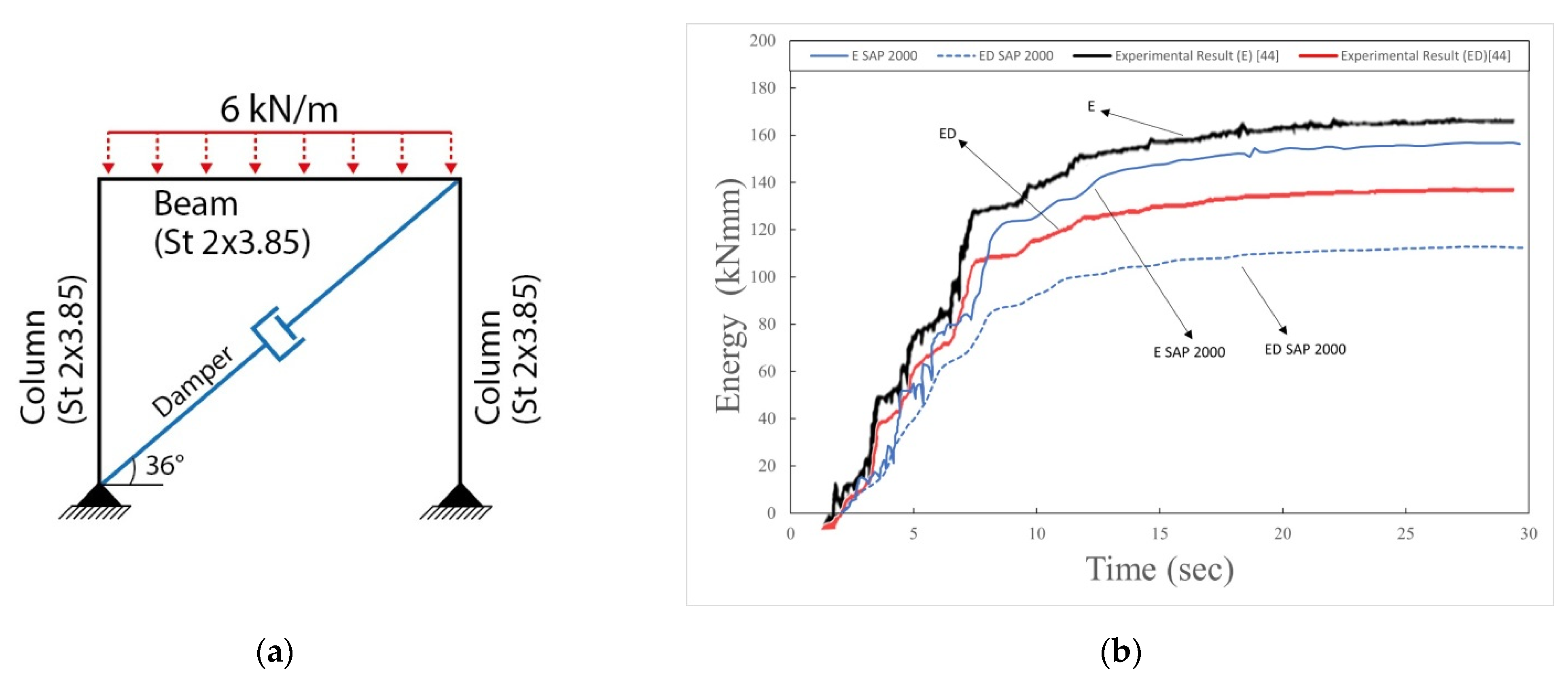
To test the performance of the SAP 2000 model containing the viscous damper, the research of Constantinou and Symans [44,51] was used. They conducted an experimental work on the seismic response of buildings upgraded with supplemental viscous dampers. For this purpose, the frame scaled to 1:4 size (Figure 6a) was designed as a one-story small structural system and tested on a shaking table simulating the natural earthquake scenarios. The damper used was a linear damper with α = 1 and a damper coefficient of 15.45 Ns/mm. The effect of viscous dampers on the behavior of the structural system to which they are attached is illustrated in graphs of the time history of the energy dissipated by various mechanisms in the structure. Figure 6b shows the energy time histories for the one-story structure subjected to the Taft earthquake. The input energy (E) and the energy dissipated by the viscous damper (Ed) are compared. It was observed that numerical model by SAP 2000 agreed well the experimental results.
4. Results and Discussion
4.1. Variation of Displacement with Story Level
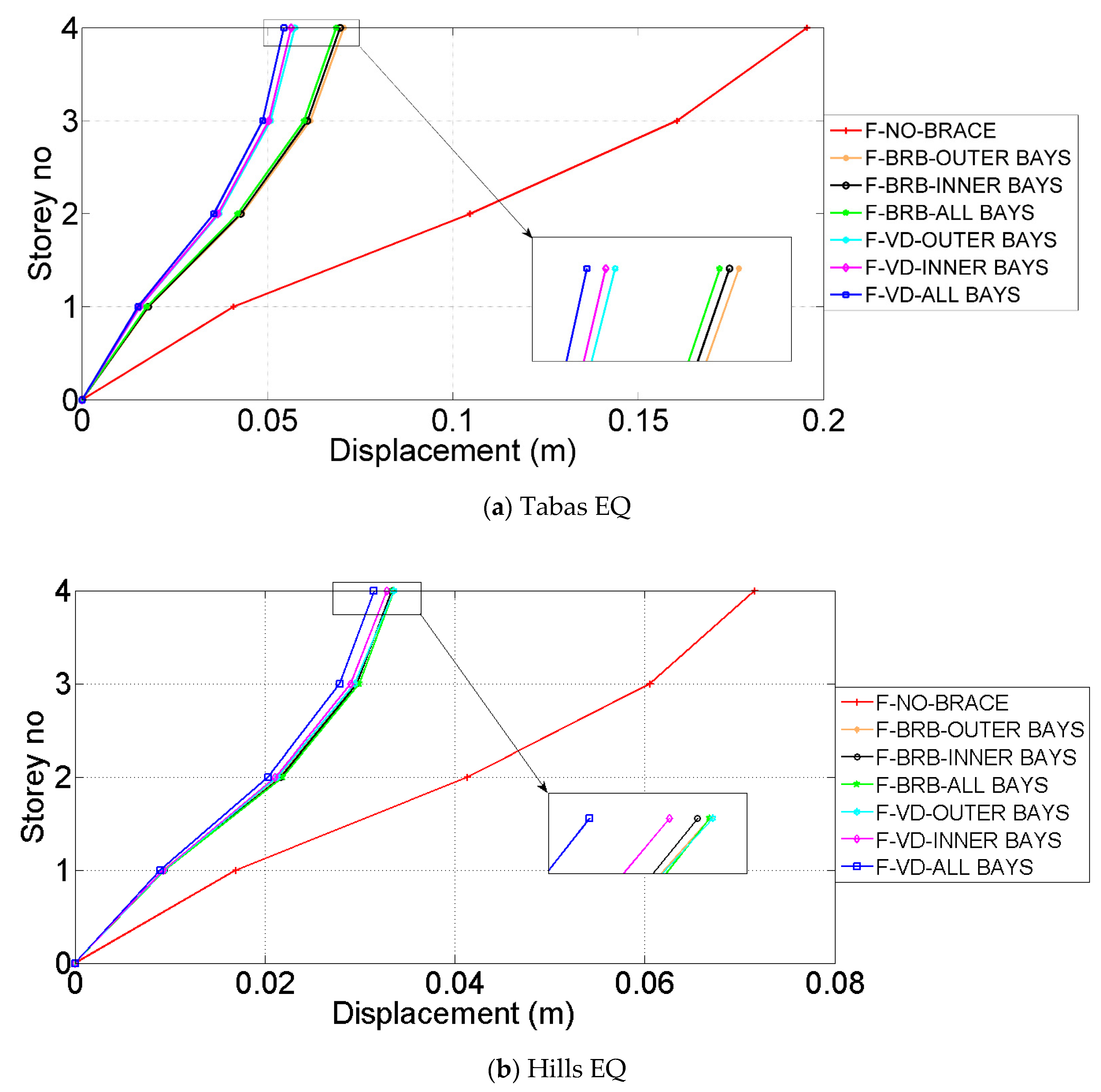
Variations of the displacements over the four-story steel frames with and without protective systems are depicted in Figure 7. The figures provided herein corresponded to the maximum and minimum displacement demands of the original frame, respectively. For instance, the Tabas earthquake gives the highest displacement of 22 cm, while the Hills earthquake results in the minimum displacement of 7 cm in the four-story models. When the VDs and BRBs were introduced to the bare frames, the relative displacements reduced remarkably from 22 cm to 5 and 7 cm, respectively. Thus, the lateral displacement demand decreased by about 77% and 68% by using VDs and BRBs, respectively. Hence, the contribution of BRB was 9% lower than that of VD as long as the reduction in the lateral displacement was taken into account. For a given protective system, the configuration has played a marked role. The all-bay systems of VDs or BRBs had better performance in reducing the displacement demand than the inner and the outer configurations.
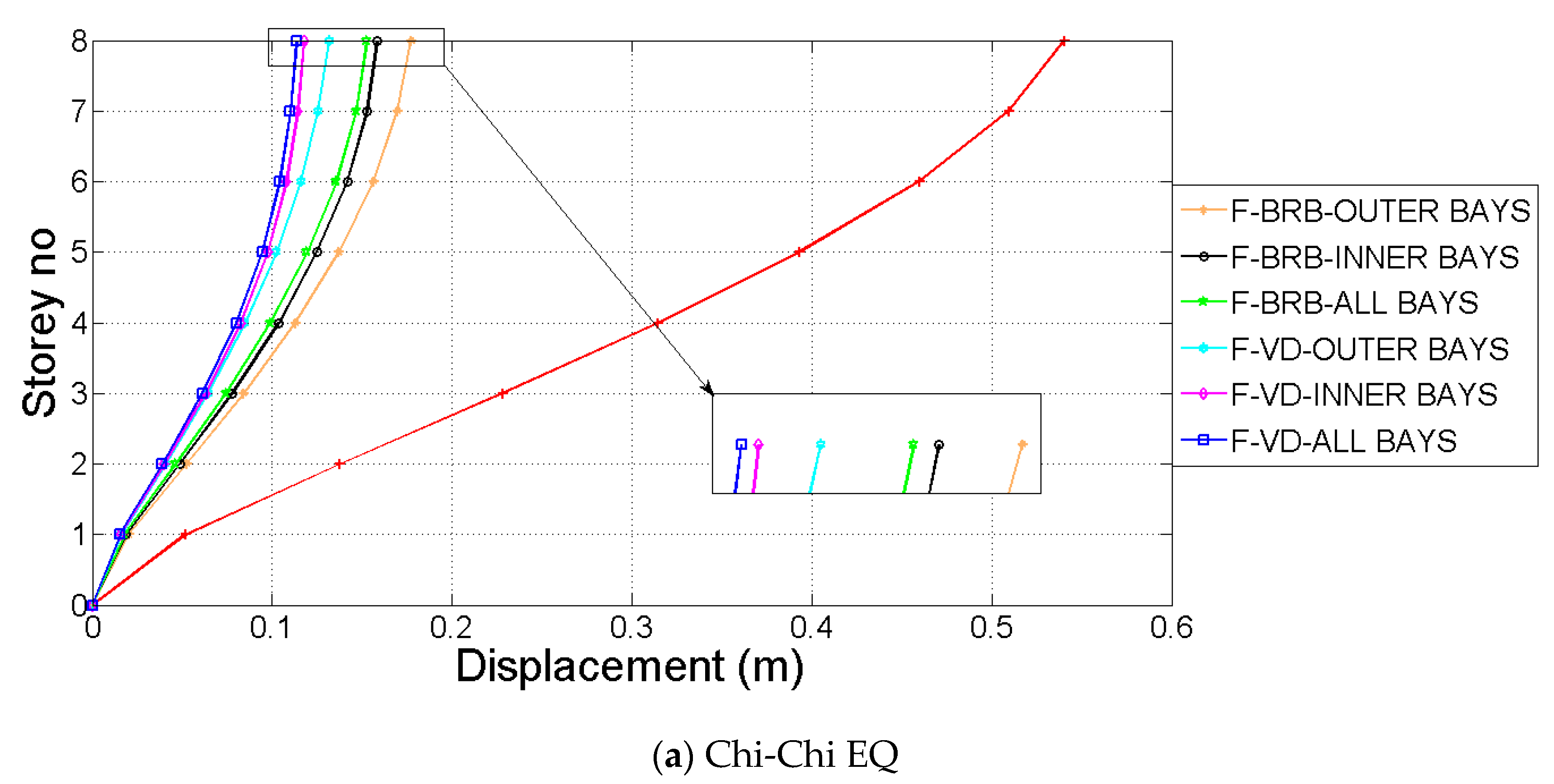
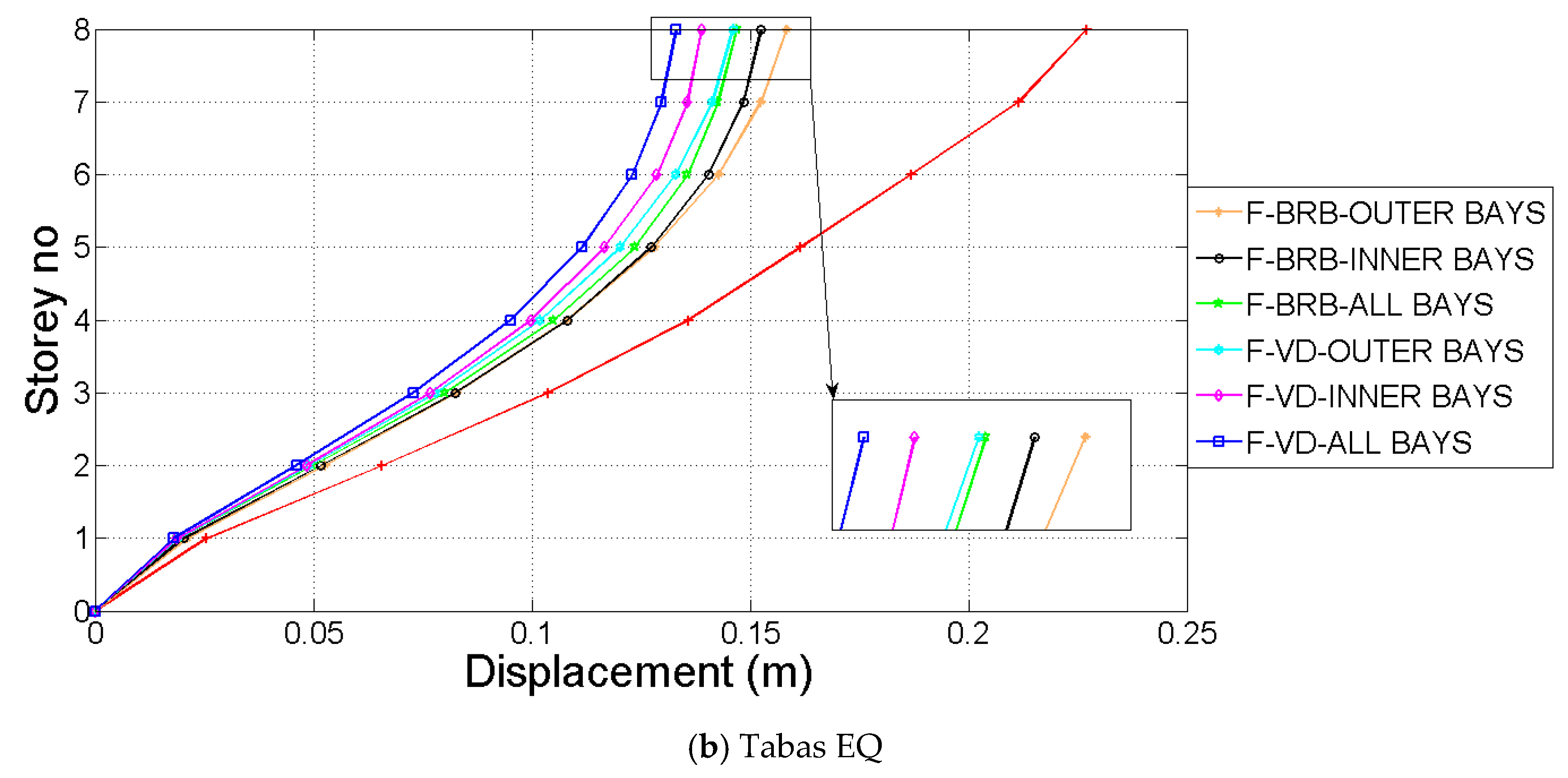
As seen in Figure 8, the maximum and minimum lateral displacements over the eight-story bare frames were 55 and 23 cm, respectively, which were achieved under the Chi-Chi and Tabas earthquakes. The most effective seismic device configuration seemed to be the all-bay system, irrespective of the ground motion exerted. As seen in Figure 8a, use of the VD and the BRB in all-bay systems provided 80% and 72% lower displacements, respectively, which decreased to 76% and 67% as long as the outer-bay system was employed. Moreover, Figure 8b suggests the effects of using VDs and BRBs to decrease the lateral displacement by about 48% and 30%, respectively. Therefore, it was clear that the rate of influence of using protective systems varied on the basis of the earthquake type.
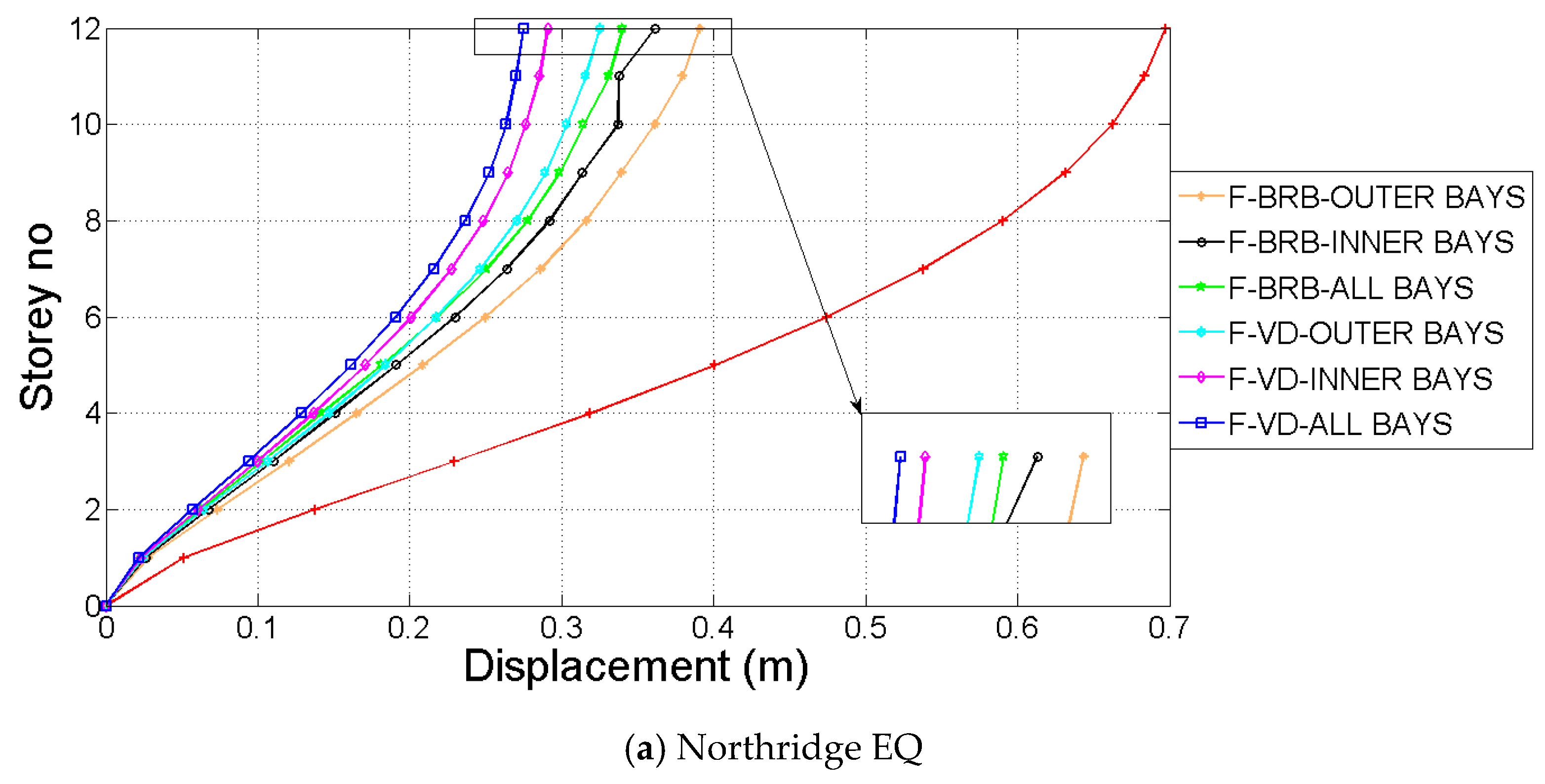
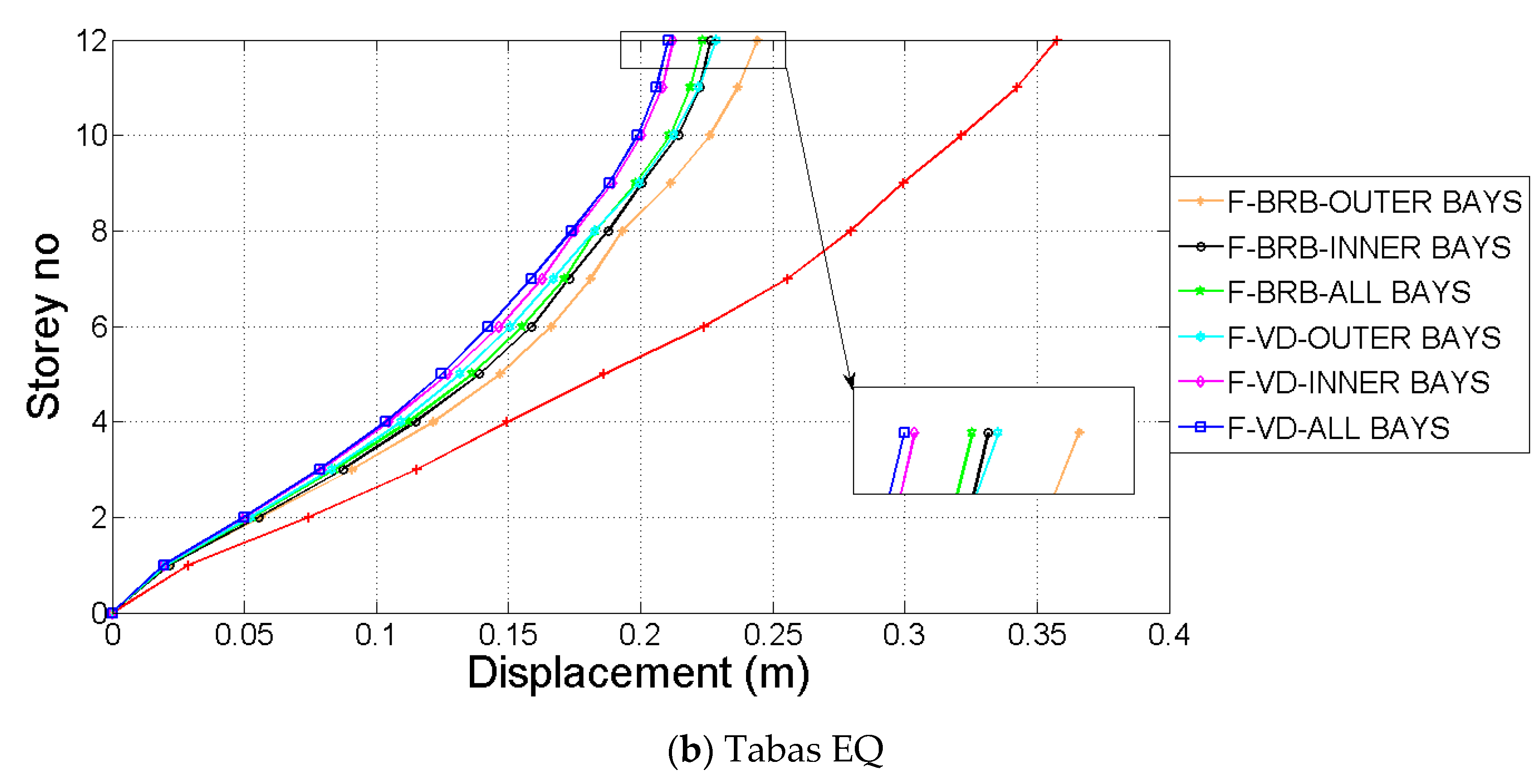
Figure 9a presents the maximum displacement demand for the 12-story frames under the Northridge earthquake. The Tabas earthquake, which yielded the maximum displacement demand in the case of four-story frames, provided the minimum values for both 8- and 12-story models. Like four-and eight-story frames, the all-bay configuration of both VDs and BRBs suggested the most favorable pattern. The former and the latter caused the maximum displacement of 70 cm to decrease to about 25 and 30 cm, which corresponded to 64% and 57% less lateral displacement demand, respectively. Those contributions of VD and BRB appeared to lessen in the case of inner and the outer-bay systems. For the latter, the effect of VD was 56%, while that of BRB was only 44% under the Northridge earthquake. Therefore, when the seismic protection pattern switched from the all bay to the outer bay, the VD and BRB had a lower influence by as much as 8% and 11%, respectively, on decreasing the lateral displacement. Moreover, the VDs showed better performance compared to the BRBs of the same configuration. It was noticeable that the percentage of the displacement reductions by using the seismic protection systems in the four-story model were higher than those in the eight-story model; hence, these reduction values in 8-story were higher than 12-story. Therefore, the VD and BRB systems have many effects on the reduction of displacement demand of the buildings under near-fault motions, so that these effects seemed to be considerable in small buildings in comparison with high-rise buildings.
4.2. Variation of Interstory Drift Ratio with Story Level
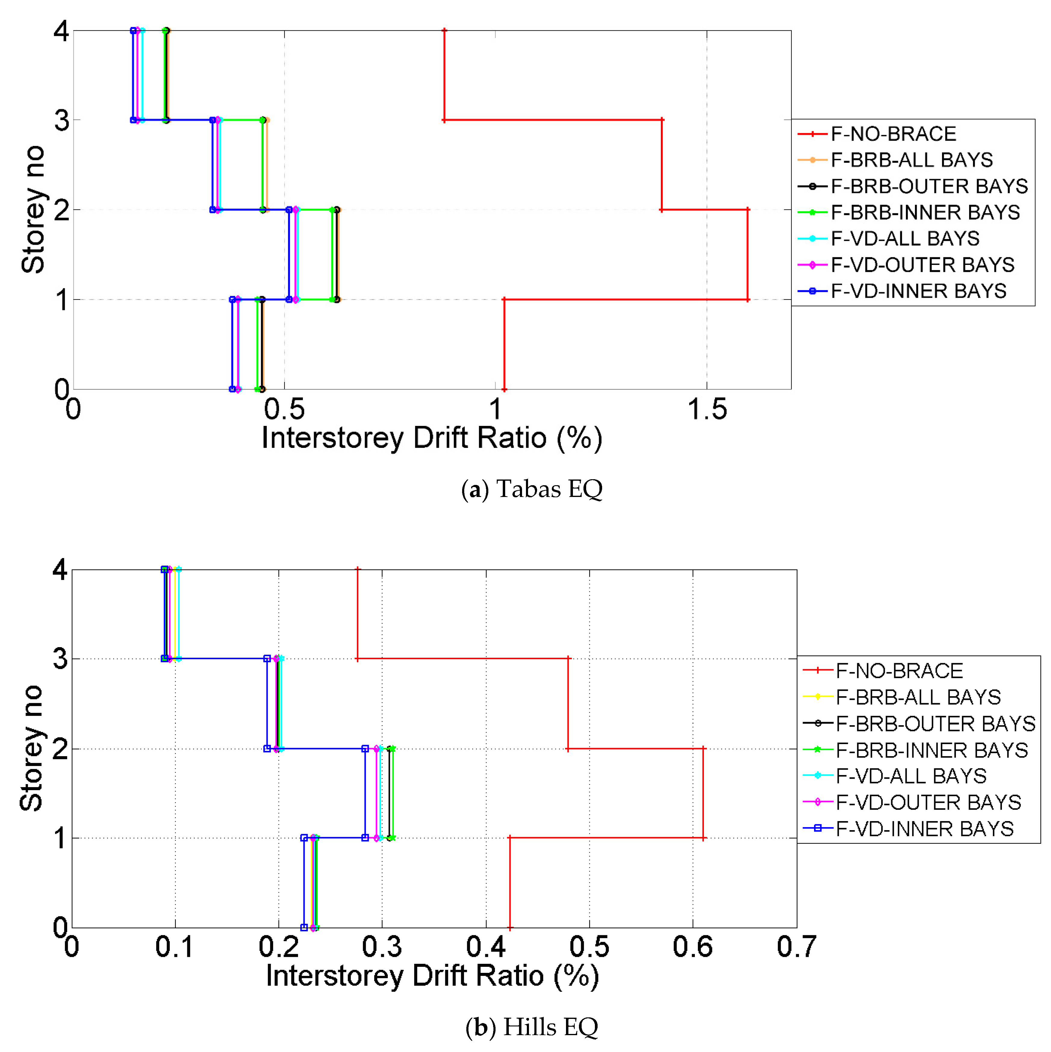
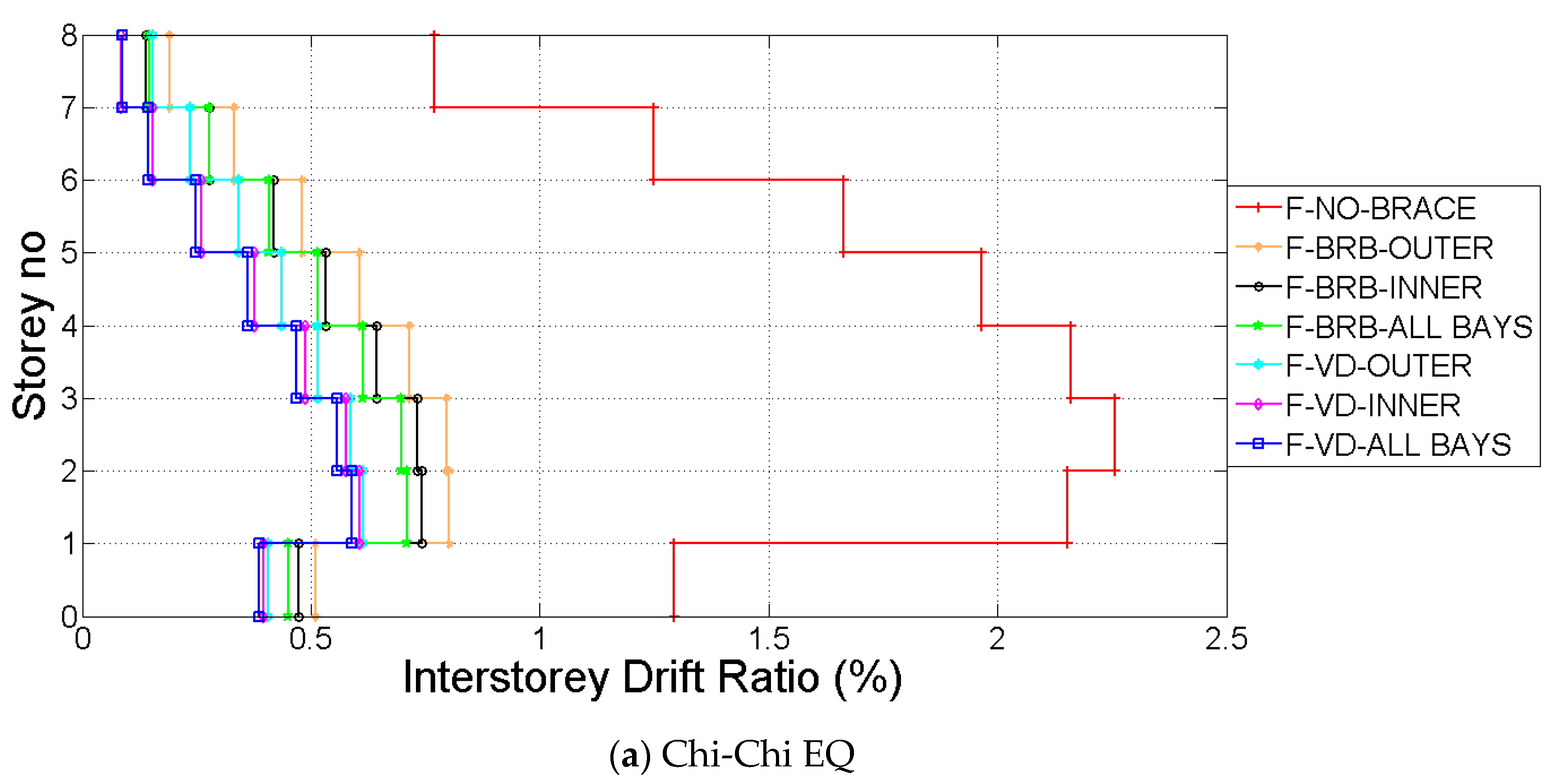
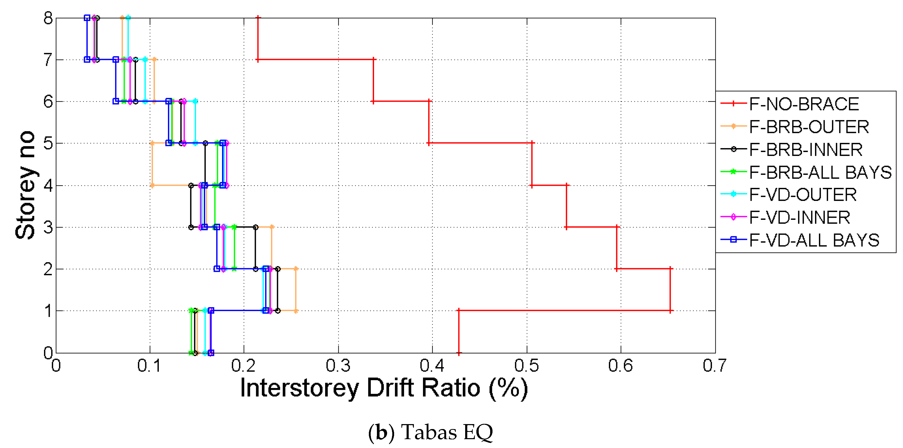
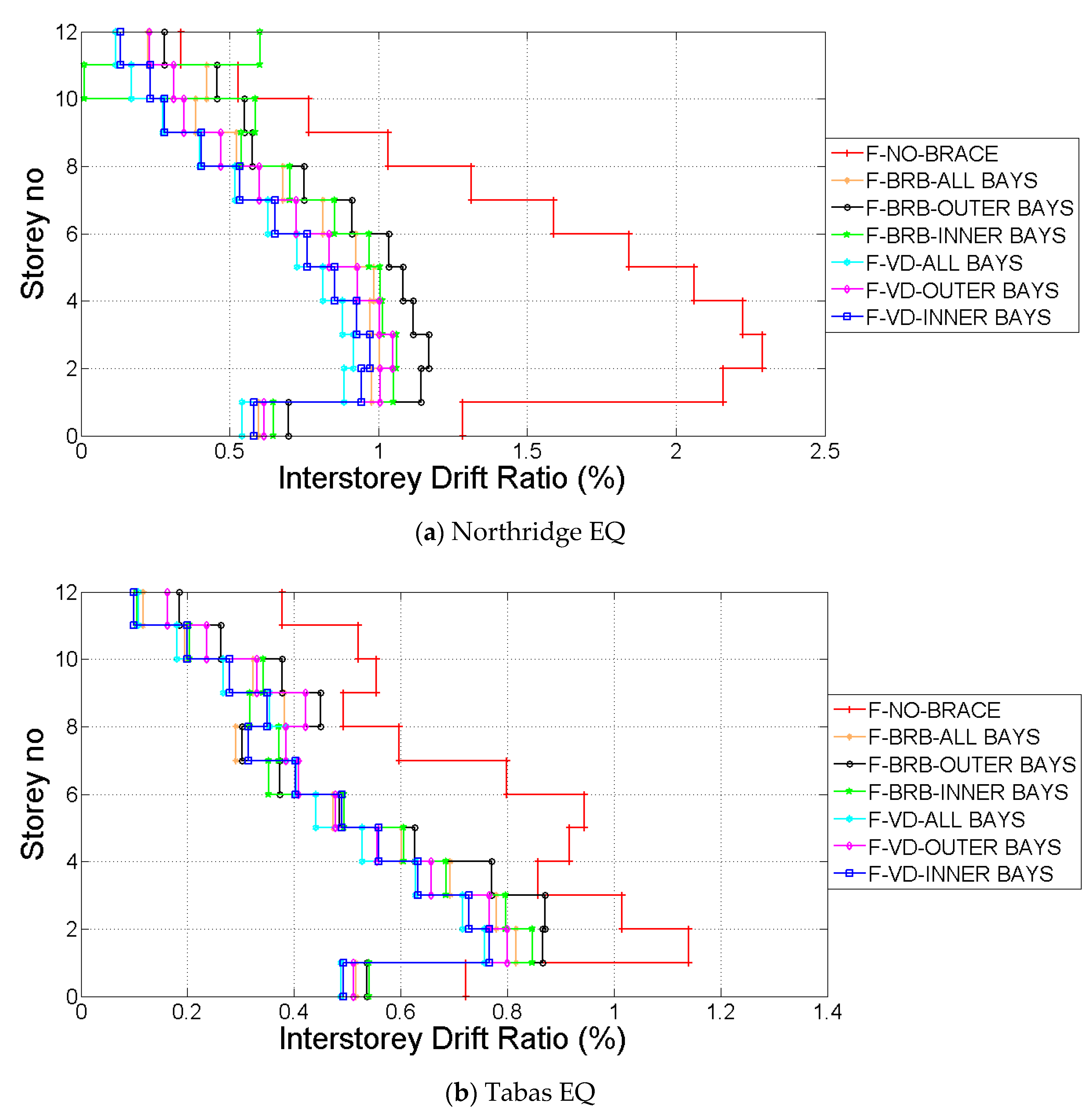
Interstory drift ratios for the models with and without seismic protection devices in 4, 8, and 12-story frames are shown in Figure 10, Figure 11 and Figure 12, respectively. The figures presented herein consist of the bare frames with maximum and the minimum drifts under a ground motion. In the four-story frames, as seen in Figure 10, the Tabas and the Chi-Chi earthquakes gave the maximum and the minimum interstory drifts of 0.60% and 1.65%, respectively. Irrespective of the excitation, the models experienced the highest drift at the second floor. The effects of using VD and BRB were to decrease the interstory drift. Indeed, the VDs provided 66% less interstory drift ratio at the second floor, while that of BRB was about 60%. Interestingly the influence of seismic protection pattern appeared to be almost negligible on the interstory drift unlike that seen in the lateral displacement. It can be observed in Figure 11 and Figure 12 that the integration pattern of those devices was more recognized. The all-bay system resulted in the highest contribution in reducing the interstory drift. Unlike the four-story one, the highest drift occurred in the third floor of the 8 and 12-story models. The VD and BRB reduced the interstory drift by 78% and 67%, respectively, in the former and 62% and 55%, respectively, in the latter. According to descriptions expressed in the case of drifts, a dramatic difference was not observed in the interstory drifts after utilizing the seismic protection devices in all models, even under increasing floor numbers under severe near-fault motions. Moreover, they seemed to be very effective in the reduction of building deformations and solve the problem in relation to the high drifts that were induced by increasing the floor numbers as well as the near-fault excitations.
4.3. Maximum Interstory Drift Ratio (IDR) and Maximum Roof Drift Ratio (RDR)
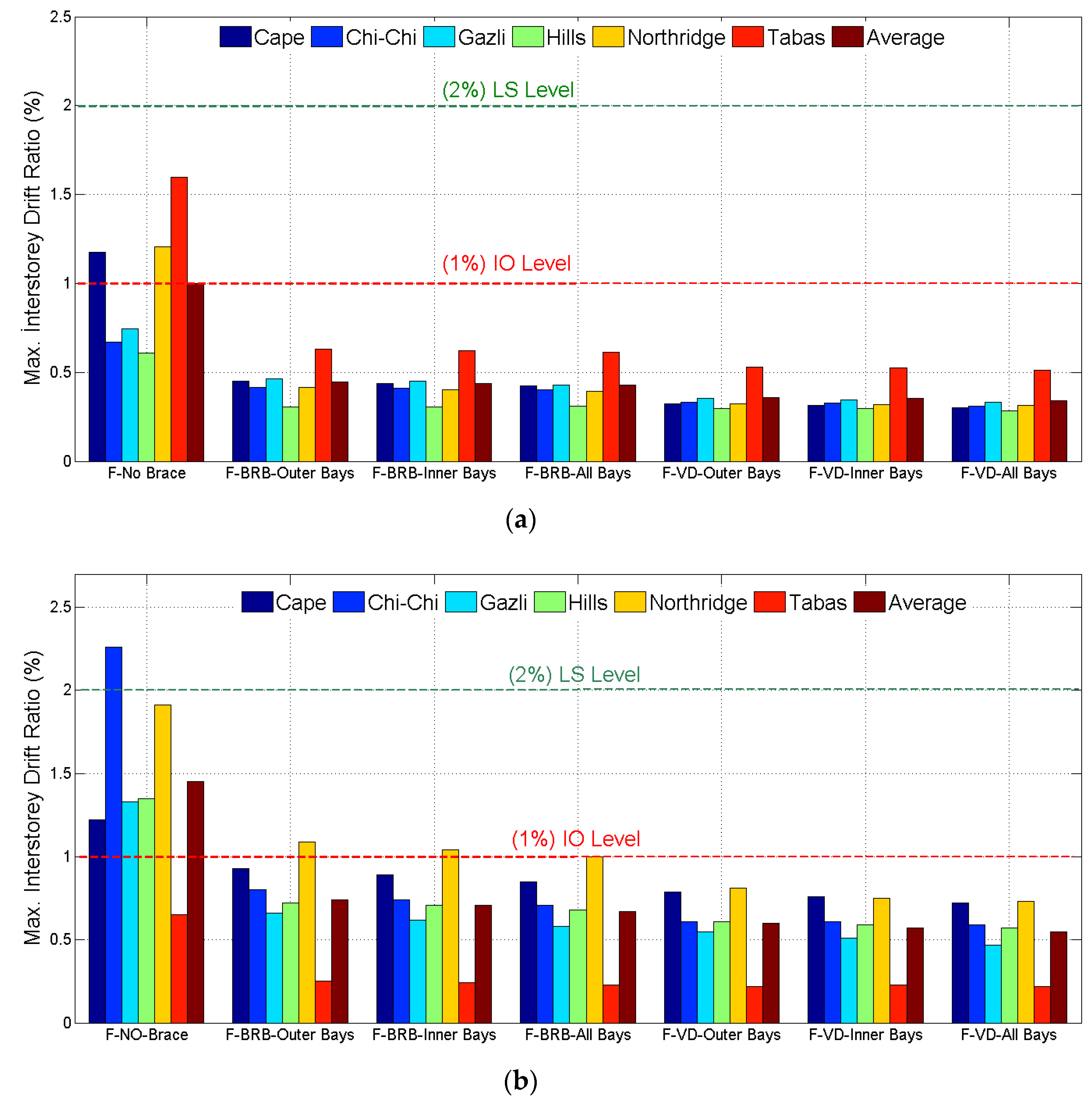
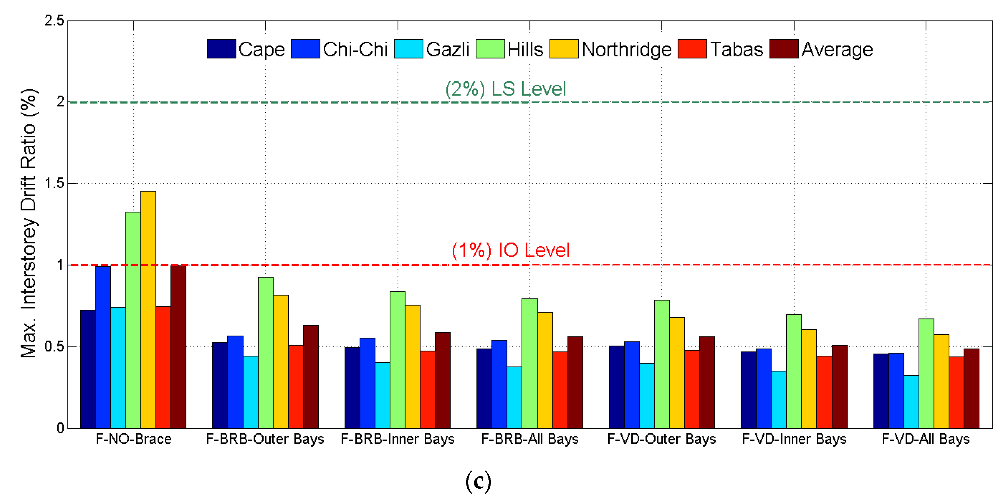
When the studies in the literature are examined, the maximum interstory drift ratio (IDR) is generally accepted as one of the basic criteria to determine the general seismic performance. Moreover, IDR is considered as the ultimate limit state boundary condition during the design of a structure. Therefore, this parameter is quite essential when evaluating structural systems under lateral forces. FEMA 273 [52] and Vision 2000 [53] suggest the following limits for the performance levels: (a) Immediate Occupancy (IO) with 1% drift, (b) Life Safety (LS) with 2% drift, (c) Collapse Prevention (CP) with 2.5% drift, and (d) Near Collapse (NC) with 3%. Figure 13 presents the maximum interstory drift ratios for the 4, 8, and 12-story models. It was observed that the IDR values of 1.6%, 2.25%, and 1.45% were monitored in the case of 4, 8, and 12-story bare frames, respectively, which were dominated by the Tabas, Chi-Chi, and Northridge earthquakes, respectively. It was evident that none of the original models in this study satisfied the immediate occupation limit state. When the BRBs and VDs were integrated into the 8- and 12-story frames, the dominating earthquakes shifted to the Cape and the Hills earthquakes, respectively, while there was no change in the prevailing earthquake in the case of the four-story frame. Moreover, all of the structures considered fell within the limit state of immediate occupancy. The change in BRB or VD configurations had a rather small effect on the maximum IDR of four- and eight-story structures, while this effect became more evident with raising the story level as observed in 12-story structure.
4.4. Variation of Maximum Absolute Acceleration with Story Level
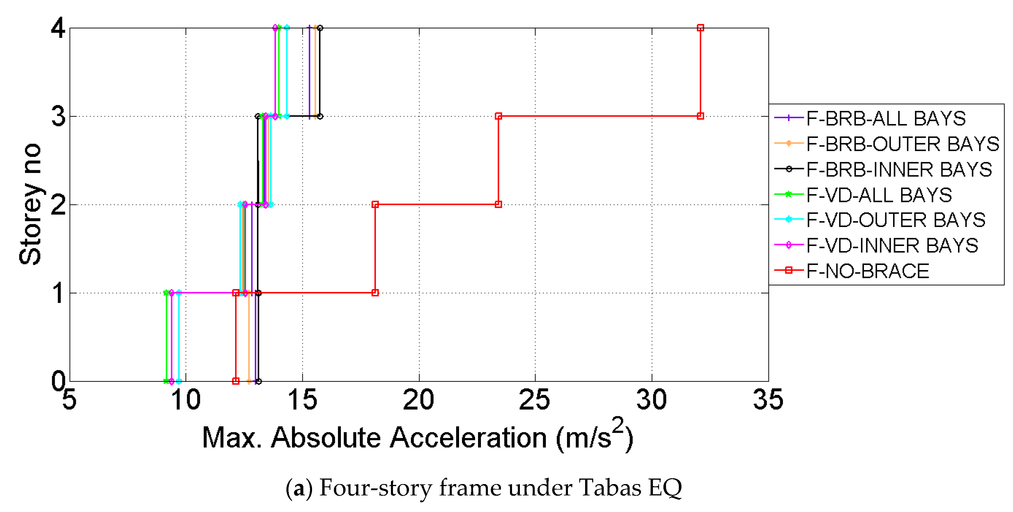
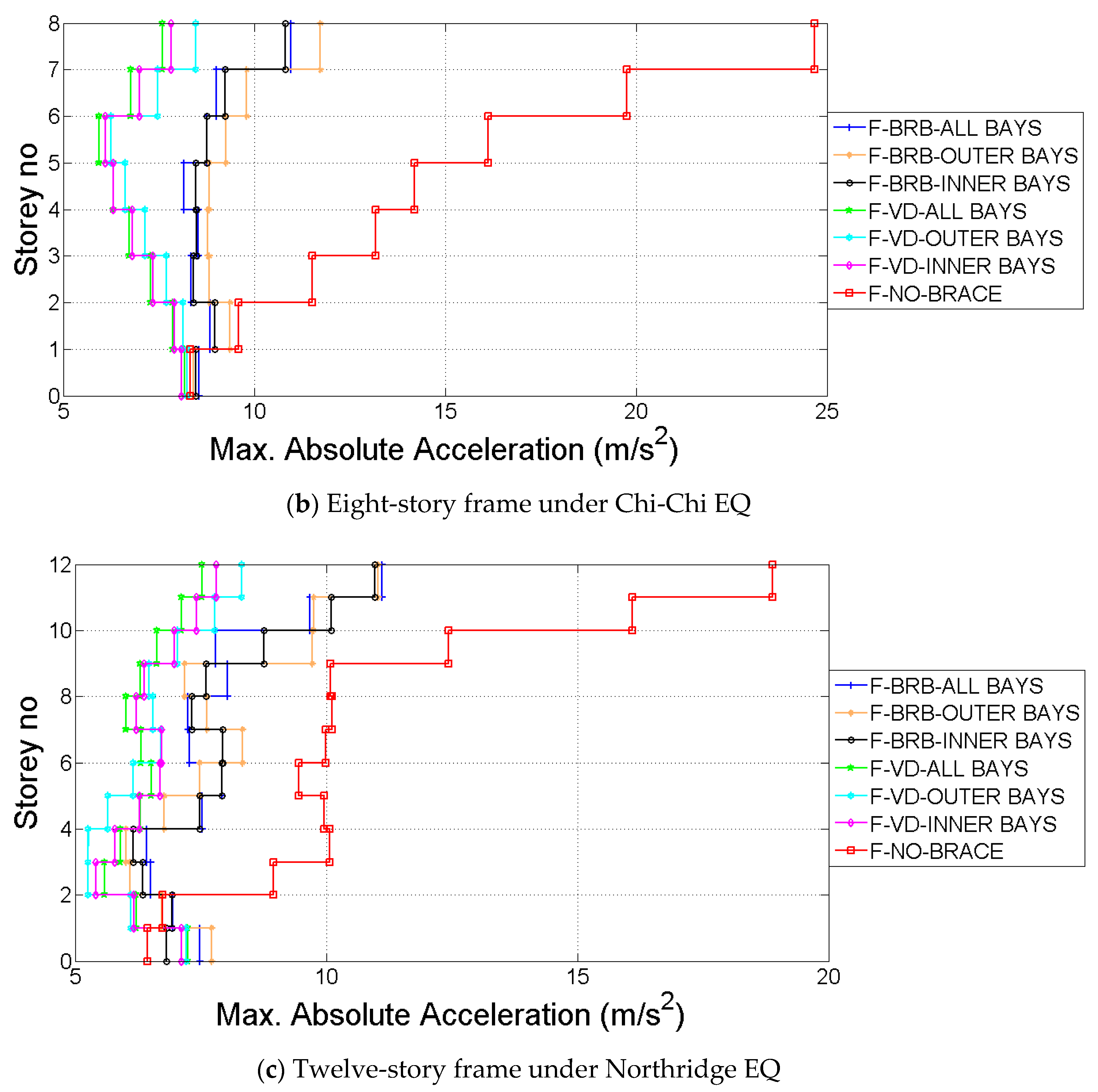
During an earthquake, the structures suffer damage, mainly because of the relative variation of maximum absolute acceleration with story level displacement of building stories to each other and acceleration developed at the building floors. The role of seismic protection, therefore, is to decrease the absolute acceleration. In this section of the present paper, the maximum acceleration of each building floor as an important parameter in assessing the effectiveness of the protective systems under the near-fault earthquake excitations are discussed. Figure 14a,c show the absolute acceleration distribution of each story at 4-, 8-, and 12-story buildings, respectively, for the bare and VD and BRB modified models.
It can be observed in Figure 14 that the responses of the maximum acceleration in each floor of VD and BRB modified buildings were remarkably reduced compared to the original building structures. The highest absolute acceleration always took place on the top floor of the four-story building irrespective of the ground motion as well as the seismic protection devices provided. However, the 8- and 12-story models experienced the maximum absolute acceleration in the middle floors as well as in the top floor. The average value of reduced floor accelerations from the three models was as high as 65% and 49% when the VD and BRB were employed in the all-bay configurations. The effect of the protective system pattern was not recognized in the 4-story model, while it was quite noticeable as the floor numbers increased to 8 and 12. When the buildings had the outer-bay system, the reducing effect of VD in the floor acceleration decreased by as much as 10%. Similarly, using BRB in the outer-bay system seemed to have almost 5% less effectiveness. Therefore, the upgrading of the frames lessened the absolute acceleration by as much as 65% such that the higher the story numbers, the greater reduction in this parameter. In line with the other seismic responses, the effect of using VDs was more noticeable compared to the BRBs. The absolute accelerations of the buildings varied with the configuration of the seismic protection.
4.5. Maximum Base Shear
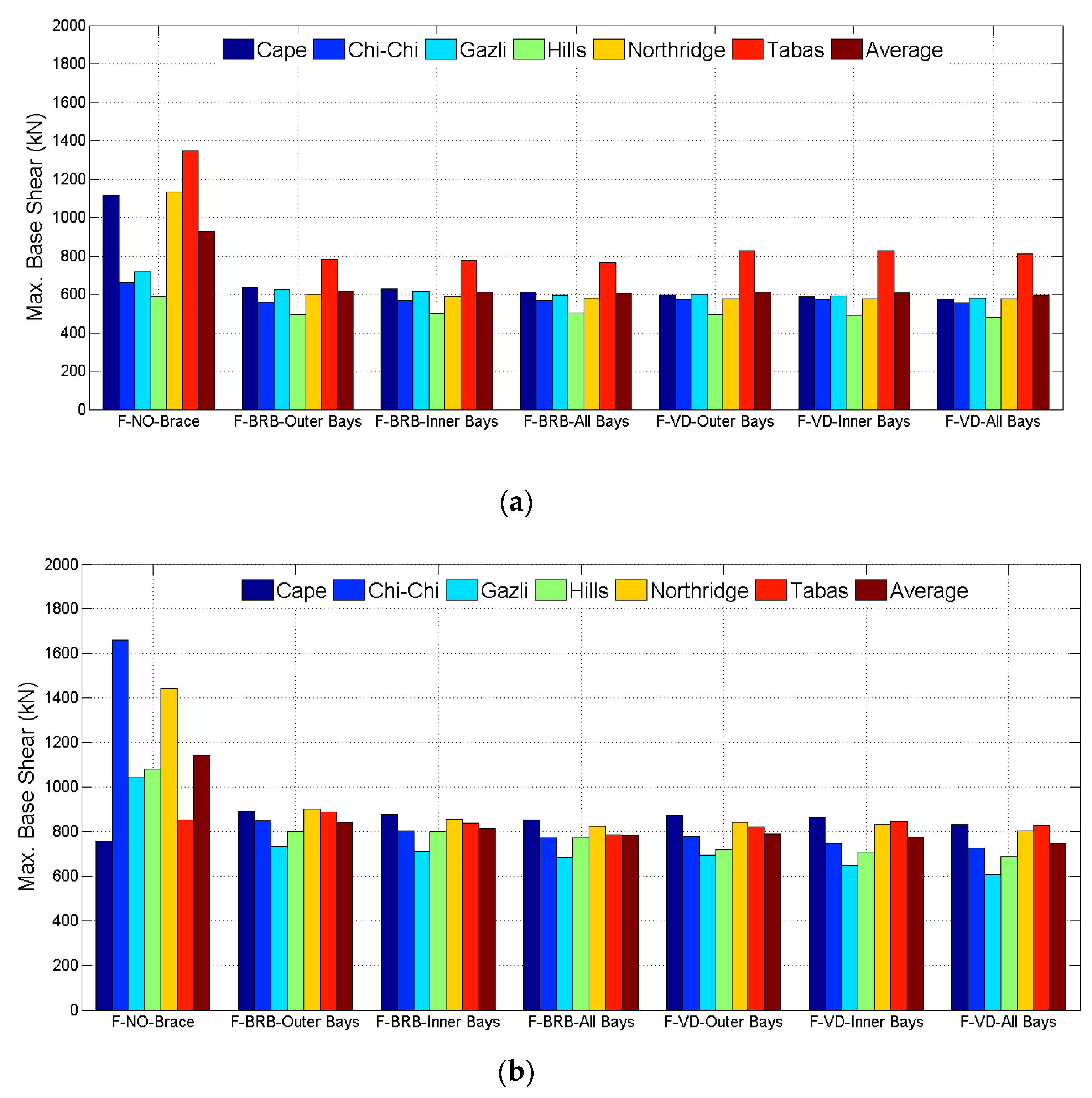
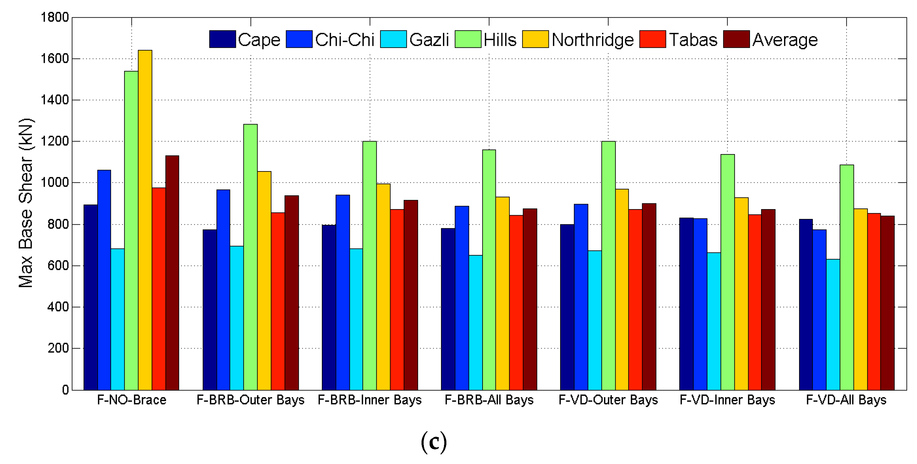
The base shear of the structural systems with and without seismic protection devices under the effects of the ground motions is presented in Figure 15. Basically, in each bare structure, different earthquake records led to different maximum base shears. Indeed, the Tabas, Chi-Chi, and Northridge earthquakes dominated the base shear of the 4-, 8-, and 12-story buildings, respectively. It can be seen in Figure 15a that the maximum base shear of 1380 kN in the four-story buildings was obtained under the Tabas earthquake that was followed by the Northridge and Cape earthquakes with associated base shears of 1175 and 1150 kN, respectively. After the bare frames had been upgraded with BRBs, the base shear decreased to as low as 820 kN, regardless of the installment pattern of the device, under the Tabas EQ. Similarly, the use of VDs caused the base shear to decrease to about 775 kN under the Tabas EQ. This finding provided a 40% and 44% reduction in the base shear of the frames with BRBs and VDs, respectively. In the case of eight-story buildings, as seen in Figure 15b, the Chi-Chi earthquake led to the highest base shear of the bare frames as 1650 kN. However, the BRB and VD upgraded frames had base shears of almost 800 and 750 kN under the same earthquake record, respectively, which in turn indicated 51% and 55% reductions. It was observed in Figure 15c that the 12-story bare frame had the highest base shear of 1650 kN under the Northridge earthquake. When the BRBs and VDs in the all-bays systems were employed, the base shear of the frames under the same earthquake reduced to about 900 and 850 kN. The use of BRB and VD in the frames provided a 45% and 48% less base shears, respectively. Moreover, the base of the buildings was not affected remarkably by the seismic protection device configuration. Indeed, the difference in base shear decrease by using BRB or VD was less about 3%.
4.6. Time History of the First Story and Roof Displacements
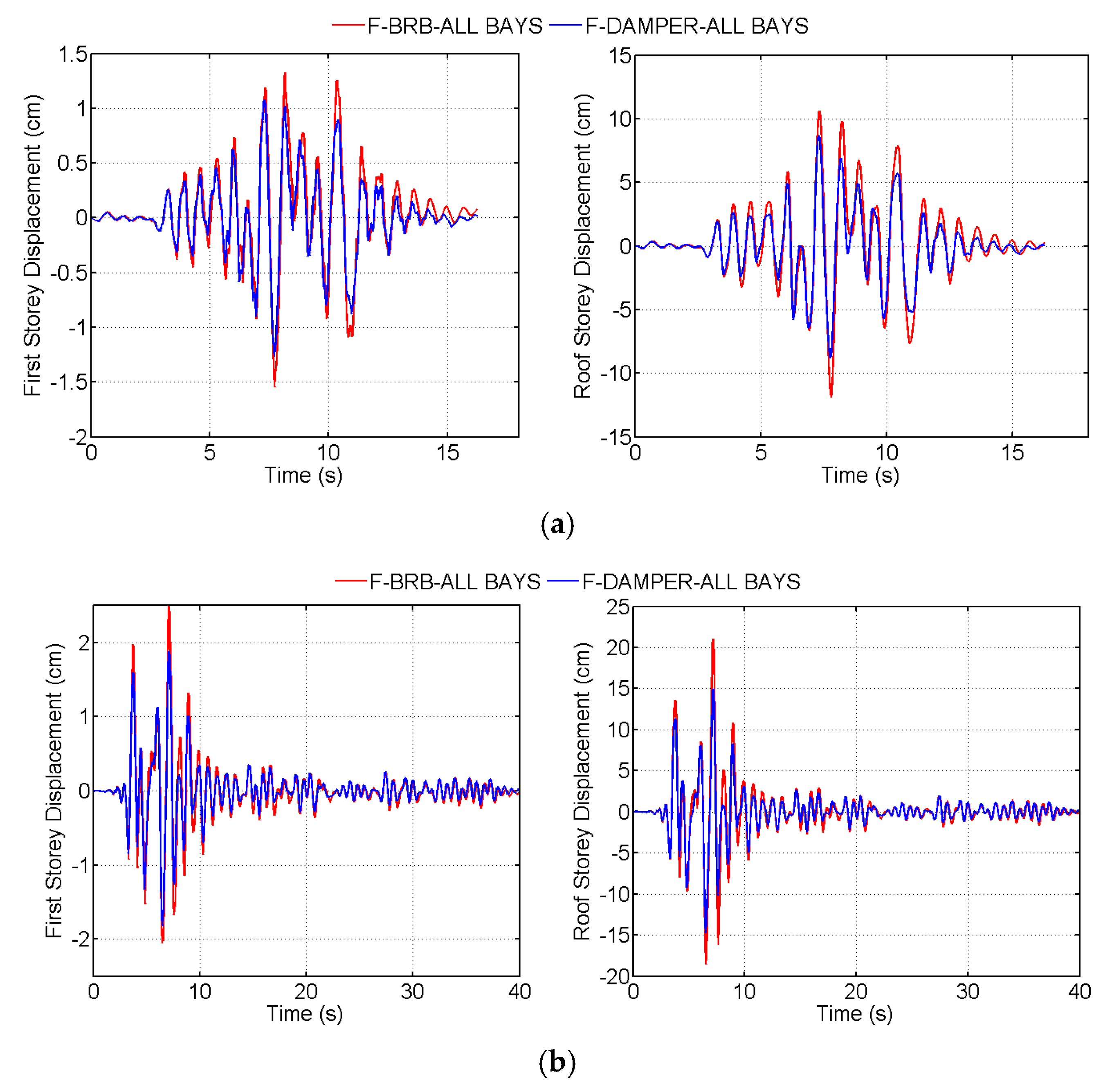
Time history of the first and the roof story displacements in the 8-story models with BRBs and VDs placed in all-bays configurations under earthquakes showing the minimum and the maximum values are illustrated in Figure 16. It was evident that the use of VDs appears to be more effective than BRB in reducing the displacement, especially at the roof level, irrespective of the story numbers in the buildings. As seen in Figure 16, the maximum displacements at the first and the roof stories in the eight-story building were reported to be 2.5 and 21 cm, as measured under the Northridge earthquake.
5. Conclusions
In this study, a nonlinear time history analysis was conducted on a set of steel buildings under six natural ground motions by means of the SAP 2000 finite element program. The buildings selected for the analysis were 4-, 8-, and 12-story steel bare frames and upgraded frames with seismic protection devices. In order to enhance the seismic performance, BRBs or VDs were placed within the outer bay, inner bay, or all bays of the frames. The contributions of the BRBs and VDs in improving the seismic performance of the structures were examined for the inelastic response parameters of the story displacement, interstory drift ratio (IDR), roof drift ratio (RDR), acceleration on the story, base shear, and time history of the first floor and roof displacements. Keeping as the benchmark that the given values below may change for varying properties of VDs and BRBs, the following conclusions are drawn on the basis of discussions above:
- The lateral displacement demand in the four- and eight-story models decreased by about 80% and 70% after adding the VDs and BRBs in the all-bay configuration, respectively. The contribution of BRB was almost 10% lower than that of VD as long as the lateral displacement was taken into account. In the 12-story building, this effect decreased to 64% and 57%, respectively. For a given protective device, the configuration played a marked role such that the all-bay systems of VDs or BRBs had better performance in reducing the displacement demand and the inner and the outer configurations took place thereafter. When the seismic protection pattern switched from the all bay to the outer bay, the VD and BRB had a lower influence on decreasing the lateral displacement by as much as 8% and 11%, respectively.
- Seismic protection devices seemed to be very effective in the reduction of building deformations. The VD and BRB reduced the interstory drifts by 78% and 67%, respectively, in the eight-story models and 62% and 55%, respectively in the 12-story models.
- The average value of reduced floor accelerations from three buildings was 65% and 49% when the VD and BRB were employed in the all-bay configurations. When the buildings had the outer-bay system, the reducing effect of VD in the floor acceleration decreased by as much as 10%.
6. Recommendations for Future Work
This study compares the performance of VD and BRB on mitigating the seismic responses of the steel structure. Therefore, the device positions and characteristics were maintained throughout the study. However, a detailed analytic process will be required to investigate the structural analysis, such as the optimal installation strategy of VD and BRB in multiple-story systems. Therefore, as further research, an optimization would be beneficial associated with the objective functions as the cost being minimized and dissipated energy that being maximized while the other seismic parameters being in the range of code provisions.
Moreover, the software utilized in this study provides accurate results for the structure without any control, but this may not be the case for controlled cases because the software uses double damping one from the link element and the other from the integration method. For this purpose, modeling the columns using the link elements would be beneficial as further research.
Author Contributions
Conceptualization, methodology, and validation, O.H.; writing—original draft preparation, O.H.; writing—review and editing, E.M.G.; visualization, O.H.; supervision and project administration, E.M.G. Both authors have read and agreed to the published version of the manuscript.
Funding
This research received no external funding.
Conflicts of Interest
The authors declare no conflict of interest.
References
- Liu, C.; Fang, D.; Zhao, L. Reflection on earthquake damage of buildings in 2015 Nepal earthquake and seismic measures for post-earthquake reconstruction. Structures 2021, 30, 647–658. [Google Scholar] [CrossRef]
- Liu, C.; Yang, W.; Yan, Z.; Lu, Z.; Luo, N. Base pounding model and response analysis of base-ısolated structures under earthquake excitation. Appl. Sci. 2017, 8, 1. [Google Scholar] [CrossRef] [Green Version]
- Ma, Y.; Gong, J.X. Probability identification of seismic failure modes of reinforced concrete columns based on experimental observations. J. Earthq. Eng. 2018, 22, 1881–1899. [Google Scholar] [CrossRef]
- Sahoo, D.R.; Chao, S.H. Performance-based plastic design method for buckling-restrained braced frames. Eng. Struct. 2010, 32, 3950–3958. [Google Scholar] [CrossRef]
- Kumar, R.G.; Satish Kumar, S.R.; Kalyanaraman, V. Behaviour of frames with, Non-Buckling bracings under earthquake loading. J. Constr. Steel Res. 2007, 654–662. [Google Scholar] [CrossRef]
- Karavasilis, L. Assessment of capacity design of columns in steel moment resisting frames with viscous dampers. Soil Dyn. Earthq. Eng. 2016, 88, 215–222. [Google Scholar] [CrossRef] [Green Version]
- Abou-Elfath, H.; Ramadan, M.; Alkanai, F.O. Upgrading the seismic capacity of existing RC buildings using buckling restrained braces. Alex. Eng. J. 2017, 56, 251–262. [Google Scholar] [CrossRef]
- AISC. Seismic Provisions for Structural Steel Buildings; American Institute of Steel Construction, Inc.: Chicago, IL, USA, 2005. [Google Scholar]
- Asgarian, B.; Amirhesari, N. Comparison of dynamic nonlinear behavior of ordinary and buckling restrained braced frames subjected to strong ground motion. Struct. Des. Tall Spec. Build. 2008, 17, 367–386. [Google Scholar] [CrossRef]
- Liu, C.; Luo, X.; Fang, D.; Shi, C.; Sarvar, S.; Zhao, B. Study on flexural stiffness of diagrid non-stiffened node based on four spring assemblage model. Eng. Str. 2019, 198, 1–9. [Google Scholar] [CrossRef]
- Liu, C.; Zhao, B.; Yang, J.; Yi, Q.; Yao, Z.; Wu, J. Effects of brace-to-chord angle on capacity of multi-linear chs x-joints under out-of-plane bending moments. Eng. Str. 2020, 211, 1–11. [Google Scholar] [CrossRef]
- Liu, C.; Fang, D. Robustness analysis of vertical resistance to progressive collapse of diagrid structures in tall buildings. Struct. Des. Tall Spec. Build. 2020, 29, 2–13. [Google Scholar] [CrossRef]
- Apostolakis, G.; Dargush, G.F. Optimal seismic design of moment-resisting steel frames with hysteretic passive devices. Earthq. Eng. Struct. Dyn. 2010, 39, 355–376. [Google Scholar] [CrossRef]
- César, M.B.; Coelho, J.P.; Gonçalves, J. Semi-active vibration control of a non-collocated civil structure using evolutionary-based belbic. Actuators 2019, 8, 43. [Google Scholar] [CrossRef] [Green Version]
- Ghanchi, N.; Kewate, S. Dynamic analysis of 25 storey RCC building with and without viscous dampers. Int. J. Sci. Eng. Res. 2015, 6, 63–68. [Google Scholar]
- Kang, J.D.; Tagawa, H. Seismic performance of steel structures with seesaw energy dissipation system using fluid viscous dampers. Eng. Str. 2013, 56, 431–442. [Google Scholar] [CrossRef]
- Marshall, J.D.; Charney, F.A. A hybrid passive control device for steel structures, I: Development and Analysis. J. Constr. Steel Res. 2010, 66, 1278–1286. [Google Scholar] [CrossRef]
- Elias, S.; Matsagar, V. Seismic vulnerability of a non-linear building with distributed multiple tuned vibration absorbers. Str. Infrastruct. Eng. 2019, 15, 1103–1118. [Google Scholar] [CrossRef]
- Lin, P.C.; Takeuchi, T.; Matsui, R. Seismic performance evaluation of single damped-outrigger system incorporating buckling-restrained braces. Earthq. Eng. Struct. Dyn. 2018, 4343–4365. [Google Scholar] [CrossRef] [Green Version]
- Wang, H.; Feng, Y.; Wu, J.; Jiang, Q.; Chong, X. Damage, Concentration Effect of Multistory Buckling-Restrained Braced Frames. Adv. Civ. Eng. 2019, 2019. [Google Scholar] [CrossRef]
- Lin, K.C.; Lin, C.C.J.; Chen, J.Y.; Chang, H.Y. Seismic reliability of steel framed buildings. Struct. Saf. 2010, 32, 174–182. [Google Scholar] [CrossRef]
- Deulkar, W.N.; Modhera, C.D.; Patil, H.S. Buckling restrained braces for vibration control of building structure. Int. J. Res. Rev. Appl. Sci. 2010, 4, 363–372. [Google Scholar]
- Di Sarno, L.; Manfredi, G. Seismic Response of Reinforced Concrete Buildings Retrofitted with Dissipative Steel Braces. J. Civ. Eng. Archit. 2010, 4, 1934–7359. [Google Scholar]
- Jankhaneh, M.E.; Ebrahimi, A.H.; Amiri, M.S. Seismic performance of steel braced frames with an all-steel buckling restrained brace. ASCE-Pract. Period. Struct. Des. Constr. 2018, 23, 2–16. [Google Scholar]
- Hosseinzadeh, S.; Mohebi, B. Seismic evaluation of all-steel buckling restrained braces using finite element analysis. J. Constr. Steel Res. 2016, 119, 116–184. [Google Scholar] [CrossRef]
- Fahiminia, M.; Zahrai, S.M. Seismic performance of simple steel frames with buckling-restrained knee braces & SMA to reduce residual displacement. Soil Dyn. Earthq. Eng. 2020, 137, 1–21. [Google Scholar]
- Symans, M.D.; Charney, F.A.; Whittaker, A.S.; Constantinou, M.C.; Kircher, C.A.; Johnson, M.W.; McNamara, R.J. Energy dissipation systems for seismic applications: Current practice and recent developments. J. Struct. Eng. 2008, 134, 13–21. [Google Scholar] [CrossRef] [Green Version]
- Yaghmaei-Sabegh, S.; Jafari-Koucheh, E.; Ebrahimi-Aghabagher, M. Estimating the seismic response of nonlinear structures equipped with nonlinear viscous damper subjected to pulse-like ground records. Structures 2020, 28, 1915–1923. [Google Scholar] [CrossRef]
- SaiChethan, K.; Sirinivas, K.S.; Ranjitha, K.P. Seismic performance evaluation of fluid viscous dampers. Int. J. Res. Eng. Technol. 2017, 6, 27–32. [Google Scholar]
- Prasad, M.L.A.; Mazumder, E.A. Use of viscous damper as an energy dissipative device in steel structures. Int. J. Mech. Prod. Eng. 2016, 4, 59–66. [Google Scholar]
- Balkanlou, V.S.; Karimi, M.R.B.; Azar, B.B.; Behravesh, A. Evaluating effects of viscous dampers on optimizing seismic behavior of structures. Int. J. Curr. Eng. Technol. 2013, 3, 1150–1157. [Google Scholar]
- Narkhede, D.I.; Sinha, R. Behavior of nonlinear fluid viscous dampers for control of shock vibrations. J. Sound Vibr. 2014, 333, 80–98. [Google Scholar] [CrossRef]
- Silvestri, S.; Gasparini, G.; Trombetti, T. A five-step procedure for the dimensioning of viscous dampers to be iınserted in building structures. J. Earthq. Eng. 2010, 14, 417–447. [Google Scholar] [CrossRef]
- Milanchian, R.; Hosseini, M. Study of vertical seismic isolation technique with nonlinear viscous dampers for lateral response reduction. J. Build. Eng. 2019, 23, 144–154. [Google Scholar] [CrossRef]
- De Domenicoa, D.; Ricciardia, G.; Takewaki, I. Design strategies of viscous dampers for seismic protection of building structures: A review. Soil Dyn. Earthq. Eng 2019, 118, 144–165. [Google Scholar] [CrossRef]
- European Communities for Standardisation. Eurocode 3. In Design of Steel Structures. Part 1.1: General Rules and Rules for Buildings; European Communities for Standardisation: Brussels, Belgium, 2004. [Google Scholar]
- European Communities for Standardisation. Eurocode 8. In Design Provisions for Earthquake Resistance of Structures. Part 1.3: General Rules. Specific Rules for Various Materials and Elements; European Communities for Standardisation: Brussels, Belgium, 2004. [Google Scholar]
- Karavasilis, T.L.; Bazeos, N.; Beskos, D.E. Maximum displacement profiles for the performance based seismic design of plane steel moment resisting frames. Eng. Struct. 2006, 28, 9–22. [Google Scholar] [CrossRef]
- Deringol, A.H.; Güneyisi, E.M. Effect of friction pendulum bearing properties on behaviour of buildings subjected to seismic loads. Soil Dyn. Earthq. Eng. 2019, 125, 12–20. [Google Scholar] [CrossRef]
- FEMA. FEMA-356. In Prestandard and Commentary for the Seismic Rehabilitation of Buildings; ASCE-American Society of Civil Engineers: Reston, VA, USA, 2000; pp. 200–518. [Google Scholar]
- SAP 2000 Advanced Structural Analysis Program; Version 12; Computers and Structures Inc.: Walnut Creek, CA, USA, 2010.
- Mazanoglu, E.C.K.; Mazanaglu, K. An optimization study for viscous dampers between adjacent buildings. Mech. Syst. Signal Process. 2017, 89, 88–96. [Google Scholar] [CrossRef]
- Makris, N.; Constantinou, M. Fractional-derivative maxwell model for viscous dampers. J. Str. Eng. 1991, 117, 2708–2724. [Google Scholar] [CrossRef]
- Constantinou, M.C.; Symans, M.D. Experimental study of seismic response of buildings with supplemental fluid dampers. Str. Des. Tall Build. 1993, 2, 93–132. [Google Scholar] [CrossRef]
- Singh, M.; Verma, N.; Moreschi, L. Seismic analysis and design with maxwell dampers. J. Eng. Mech. 2003, 129, 273–282. [Google Scholar] [CrossRef]
- Akcelyan, S.; Lignos, D.G.; Hikino, T. Adaptive numerical method algorithms for nonlinear viscous and bilinear oil damper models subjected to dynamic loading. Soil Dyn. Earthq. Eng. 2018, 113, 488–502. [Google Scholar] [CrossRef] [Green Version]
- PEERC. The pacific earthquake engineering research center. In User’s Manual for the PEER Ground Motion Database Application; University of California: Berkeley, CA, USA, 2011. [Google Scholar]
- American Society of Civil Engineers ASCE. Minimum Design Loads for Buildings and Other Structures; ASCE: Reston, VA, USA, 2010. [Google Scholar]
- Palmer, K.D.; Christopulos, A.S.; Lehman, D.E.; Roeder, C.W. Experimental evaluation of cyclically loaded, large-scale, planar and 3-d buckling-restrained braced frames. J. Constr. Steel Res. 2014, 101, 415–425. [Google Scholar] [CrossRef]
- Christopulos, A.S. Improved Seismic Performance of Buckling Restrained Braced Frames. Master’s Thesis, University of Seattle, Seattle, WA, USA, 2005. [Google Scholar]
- Constantinou, M.C.; Symans, M.D. Experimental and Analytical Investigation of Seismic Response of Structures with Supplemental Fluid Dampers; Tech Report-NCEER 92 0032; State University of Newyork at Buffalo: Buffalo, NY, USA, 1992. [Google Scholar]
- FEMA. FEMA 273. In NEHRP Guidelines for the Seismic Rehabilitation of Buildings; Federal Emergency Management Agency: Washington, DC, USA, 1997. [Google Scholar]
- Vision 2000. Conceptual Framework for Performance Based Seismic Engineering of Buildings; Structual Engineers Association of Sacramento: California, CA, USA, 1995. [Google Scholar]
Figure 1.
Elevation view of the frames with none bracing and with seismic protection devices.

Figure 2.
Section view of buckling restrained braces (BRBs) (Adapted with permission from [5]).
Figure 2.
Section view of buckling restrained braces (BRBs) (Adapted with permission from [5]).

Figure 3.
Uniaxial plasticity properties of bracing (Adapted with permission from [5]).
Figure 3.
Uniaxial plasticity properties of bracing (Adapted with permission from [5]).

Figure 4.
(a) Section view of viscous damper (VD), (b) idealized force–displacement relationship for VD, (c) schematic view of Maxwell model (Adapted with permission from [30]).
Figure 4.
(a) Section view of viscous damper (VD), (b) idealized force–displacement relationship for VD, (c) schematic view of Maxwell model (Adapted with permission from [30]).

Figure 5.
(a) Geometry of the BRB-testing frame (Adapted with permission from [49,50]) and verification of SAP 2000 model against the experimental results of BRB (b) BRB05 and (c) BRB01.

Figure 6.
(a) Geometry of the VD testing frame (Adapted with permission from [44,51]) and (b) Verification of SAP 2000 model against the experimental results of VD.

Figure 7.
Variation of displacement with story level in 4-story frames.

Figure 8.
Variation of displacement with story level in 8-story frames.


Figure 9.
Variation of displacement with story level in 12-story frames.


Figure 10.
Variation of interstory drift ratio with story level in 4-story frames.

Figure 11.
Variation of interstory drift ratio with story level in 8-story models.


Figure 12.
Variation of interstory drift ratio with story level in 12-story frames.

Figure 13.
The maximum interstory drift ratio in (a) 4-, (b) 8-, and (c) 12-story frames.


Figure 14.
Variation of the maximum absolute accelerations with story level.


Figure 15.
Maximum base shear in (a) 4-, (b) 8-, and (c) 12-story frames.


Figure 16.
Displacement time history under (a) Gazlı and (b) Northridge earthquakes, showing the minimum and maximum values for the 8-story frames with BRBs and VDs.
Figure 16.
Displacement time history under (a) Gazlı and (b) Northridge earthquakes, showing the minimum and maximum values for the 8-story frames with BRBs and VDs.


Table 1.
Properties of the ground motion accelerations.
| Name | Year | Mw | Rjb (km) | Rrup (km) | Vs30 (m/s) | PGA (g) | PGV (cm/s) |
|---|---|---|---|---|---|---|---|
| Cape | 1992 | 7.01 | 0 | 8.2 | 712.8 | 0.66 | 82.1 |
| Gazlı | 1976 | 6.8 | 3.9 | 5.5 | 659.6 | 0.72 | 65.39 |
| Northridge | 1994 | 6.69 | 0 | 5.3 | 441 | 0.84 | 122.7 |
| Hills | 1987 | 6.54 | 0.9 | 0.9 | 348.7 | 0.41 | 106.74 |
| Chi-Chi | 1999 | 7.62 | 0.6 | 0.6 | 305.9 | 0.82 | 127.8 |
| Tabas | 1978 | 7.35 | 1.8 | 2 | 766.8 | 0.80 | 118.29 |
Mw: Magnitude; Rjb: Distance of surface projection; Rrup: Distance of rupture; Vs30: Average shear velocity over 30 m; PGA: Peak ground acceleration; PGV: Peak ground velocity.
Publisher’s Note: MDPI stays neutral with regard to jurisdictional claims in published maps and institutional affiliations. |
© 2021 by the authors. Licensee MDPI, Basel, Switzerland. This article is an open access article distributed under the terms and conditions of the Creative Commons Attribution (CC BY) license (https://creativecommons.org/licenses/by/4.0/).
Share and Cite
MDPI and ACS Style
Hansu, O.; Güneyisi, E.M. Comparison of Novel Seismic Protection Devices to Attenuate the Earthquake Induced Energy. Actuators 2021, 10, 73. https://0-doi-org.brum.beds.ac.uk/10.3390/act10040073
AMA Style
Hansu O, Güneyisi EM. Comparison of Novel Seismic Protection Devices to Attenuate the Earthquake Induced Energy. Actuators. 2021; 10(4):73. https://0-doi-org.brum.beds.ac.uk/10.3390/act10040073
Chicago/Turabian StyleHansu, Osman, and Esra Mete Güneyisi. 2021. "Comparison of Novel Seismic Protection Devices to Attenuate the Earthquake Induced Energy" Actuators 10, no. 4: 73. https://0-doi-org.brum.beds.ac.uk/10.3390/act10040073
Note that from the first issue of 2016, this journal uses article numbers instead of page numbers. See further details here.