
Analytical Modeling and Simulation of S-Drive Piezoelectric Actuators


Department of Electrical Engineering, Auburn University, Auburn, AL 36849, USA
*
Author to whom correspondence should be addressed.
Actuators 2021, 10(5), 87; https://0-doi-org.brum.beds.ac.uk/10.3390/act10050087
Submission received: 24 February 2021
/
Revised: 19 April 2021
/
Accepted: 23 April 2021
/
Published: 25 April 2021
(This article belongs to the Special Issue Miniature and Micro-Actuators)
Abstract
:This paper presents a structural geometry for increasing piezoelectric deformation, which is suitable for both micro- and macro-scale applications. New and versatile microstructure geometries for actuators can improve device performance, and piezoelectric designs benefit from a high-frequency response, power density, and efficiency, making them a viable choice for a variety of applications. Previous works have presented piezoelectric structures capable of this amplification, but few are well-suited to planar manufacturing. In addition to this manufacturing difficulty, a large number of designs cannot be chained into longer elements, preventing them from operating at the macro-scale. By optimizing for both modern manufacturing techniques and composability, this structure excels as an option for a variety of macro- and micro-applications. This paper presents an analytical compact model of a novel dual-bimorph piezoelectric structure, and shows that this compact model is within 2% of a computer-distributed element model. Furthermore it compares the actuator’s theoretical performance to that of a modern actuator, showing that this actuator trades mechanical efficiency for compactness and weight savings.
1. Introduction
Applications of the inverse piezoelectric effect have been limited to a high-force, low-deflection regime due to the piezoelectric effect’s generation of low strain, on the order of 0.1% [1] at a maximum, even for highly optimized materials. This low strain requires amplification of the deflection for a majority of applications. A number of designs exist for amplifying the deflection of a piezoelectric element [2], with the majority of these suffering from low active element density. These designs require a large amount of passive material to amplify to large deflections, decreasing the energy density of the overall actuator. In addition to their low density, these designs are rarely chained together to make longer actuators. This lack of flexibility and performance limits their usefulness in all but the most specific of applications.
One extant class of actuator which avoids these problems is telescoping actuators [3]. These actuators employ a series of meandering piezoelectric cylinders to gradually build displacement through the chain. Therefore, the displacement amplification is equal to the number of shells. While these actuators do excel in high-force and low-displacement applications, they are not suited to modern microfabrication techniques as they are highly non-planar. Planar designs operating on the same principles have been presented [4], but these still suffer from relatively low displacement amplification.
A second class of actuators that can greatly amplify generated strain, typically called flextensional actuators, does so through the trigonometric amplification of large contiguous piezoelectric elements [5,6,7]. This approach benefits from relatively simple designs, which are well-suited to planar manufacturing [8]. By varying geometric parameters, these actuators can be designed for a range of forces and deflections. The direction of actuation depends on the polarity of the coefficient for the material used. This dependence means that a single material and geometry cannot be used to generate both expanding and contracting actuators that exceed the coercive fields [9]. Staying below the coercive field, while possible, reduces the maximum force for actuators substantially. Due to this limitation, actuators of this class needing to operate in the inverse of the material’s piezoelectric coefficient suffer as compared to other actuator designs.
The final class of actuator discussed here is based on bimorphs. This class is both composable and amplifies strain to great extremes. Of the simple amplification schemes, bimorphs have the highest active to passive material ratio, making them ideal for large amplifying chains. Despite this advantage, simple bimorphs’ curved displacement makes them unsuitable for chained geometries, necessitating modifications. By attaching two bimorphs end-to-end, the curvature can be counteracted [10,11]. These designs benefit from high geometric amplification ratios and compact chained element spacing. This paper presents and discusses an iteration on this type of actuator that is well-suited to modern planar manufacturing techniques.
2. Materials and Methods
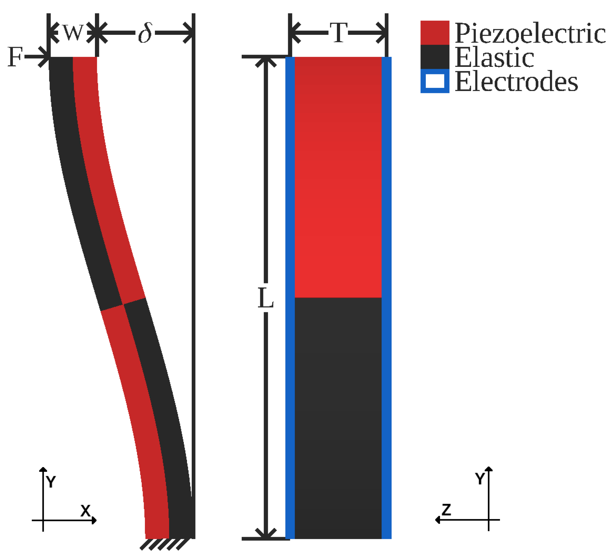
As mentioned above, bimorph-based designs can easily improve on the basic geometry by joining two end-to-end. As can be seen in Figure 1, this modification creates a structure that, when actuated, forms a slight S shape, and more importantly, keeps both endpoints parallel throughout the range of travel. This parallelism facilitates the attachment of both loads or other s-drives to the structure. Typically, in a bimorph, the electrodes are separated along the width axis of Figure 1. This electrode arrangement is problematic, chaining multiple devices together, as it requires a complex routing of wires to connect subsequent elements. Thus, in this geometry, the electrodes are separated along the thickness axis instead of the width axis of the structure (Figure 1).
Notably, this geometry can use piezoelectric materials with both positive and negative piezoelectric coefficients simply by switching the elastic and piezoelectric layers. This flexibility allows for a manufacturing process to select any material and still make both contracting and expanding actuators. Additionally, the single poling direction for all piezoelectric regions allows for the poling to be done by the electrodes themselves, further simplifying the manufacturing process.
2.1. Analytical Model
Before s-drives can be used as micro- or macro-actuators, their constituent equations must be found. As with most electrical actuators, the primary terms of interest are blocking force and free deflection as a function of the input voltage.
2.1.1. Free Deflection
For deflection, an s-drive can be modeled as simply double that of one of its two corresponding heterogeneous bimorphs. Smits et al. [12] has (1). Modifying this relationship for an s-drive yields (2), which also compensates for the abnormal axis on which the electric field is applied in this geometry.
where K is:
is the piezoelectric coefficient. and are from the compliance matrices of the piezoelectric and elastic materials, respectively. and are the widths of the piezoelectric and elastic layer, respectively. For bulk elastic materials that have no compliance matrix, the young’s moduli, and for piezoelectric and elastic, respectively, can be used to calculate compliance through
2.1.2. Blocking Force
While Smits et al. [12] have equations for the blocking force of a bimorph, those assume that rotation of the tip is unconstrained. This assumption does not hold true for an s-drive. Instead, Euler–Bernoulli beam theory can be used to find the stiffness of a cantilever as
where E is the Young’s modulus and I is the second moment of area for the actuator. A full s-drive does not take the same shape as a cantilever but each half does, and so the full s-drive can be approximately modeled as two cantilevers of length in series, yielding
Furthermore, in (6) must account for the differing Young’s moduli in the two materials. This adjustment involves calculating the second moment of area of the two material halves about the central axis of the beam, yielding
2.1.3. Chain Stiffness
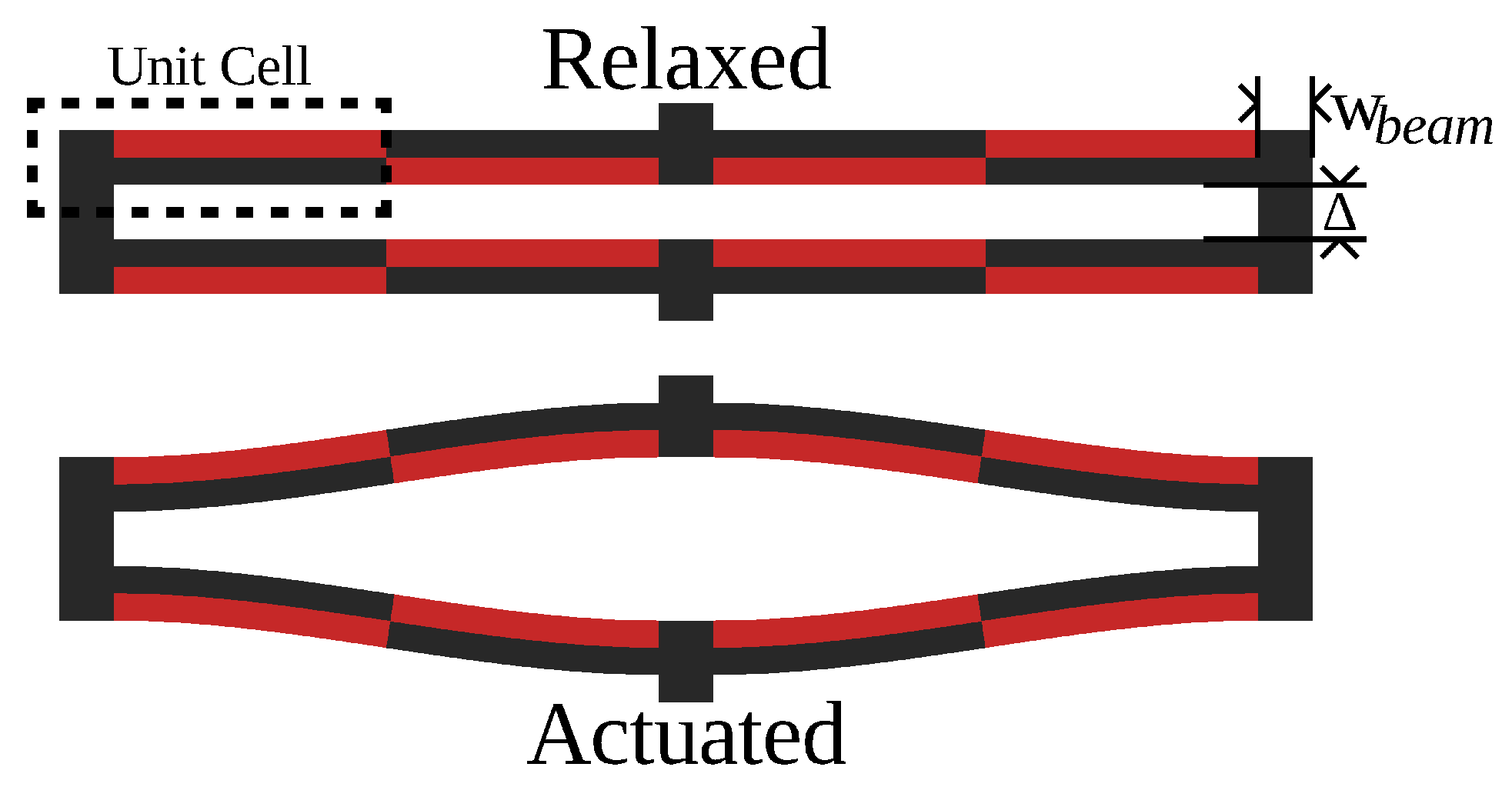
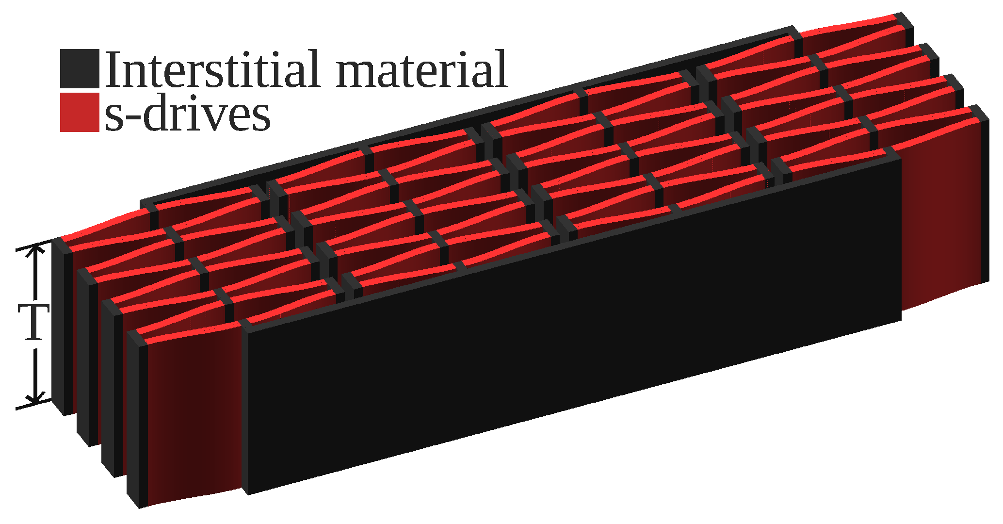
In certain MEMS applications, and certainly in macro-applications, chaining multiple actuators in sequence may be required to achieve the desired deflection. Figure 2 shows a possible geometry for realizing this chain. Figure 3 shows this geometry both being chained in series and working in parallel. Notably, due to the abnormal axis of the applied electric field, this design does not need additional wires between chained elements, as the electrodes are contiguous, simplifying manufacturing.
The free deflection of such a geometry is , where N is the number of s-drives in series. Blocking force is not as trivial, as the connecting beams add compliance to the structure, reducing the total stiffness. Balakrisnan et al. [13] modeled meandering springs, and the approach found the stiffness of a single unit cell, which is defined in Figure 2. The bulk stiffness is the combination of all the unit cells, and the unit cell stiffness is the cantilever stiffness combined with that of the adjoining beam connected to a rigid moment arm. A more thorough derivation can be found in Balakrisnan et al., but the final form for this stiffness is in (9). Combining (9) with that of the cantilever (5) is (10) and the entire geometry is (11):
This model from Balakrisnan et al., only works well when and .
3. Results
3.1. Analytical Model Versus Simulations
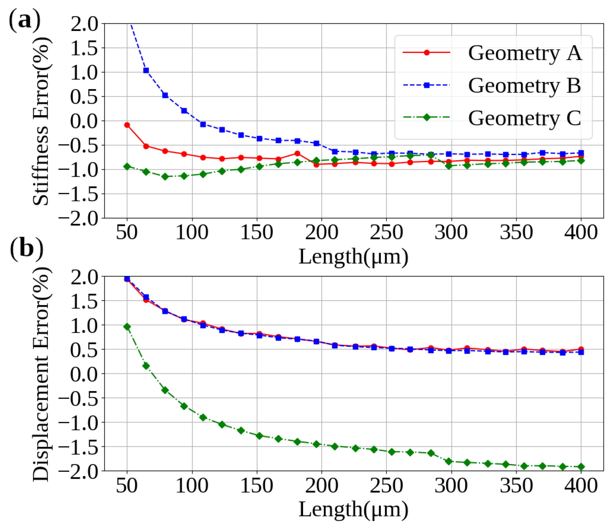
COMSOL Multiphysics® was used to verify the model. The geometry in Figure 2 was imported into the software, with a variety of geometries that can be seen in Table 1. The material properties applied were the built-in specifications for PZT-5H and aluminum for the piezoelectric and elastic layers, respectively. The length parameter for each geometry was varied from 50 to 400 , while the thickness and applied voltage were held constant at 2 and 8 , respectively. This method generates an electric field of 4 which is approximately the upper limit of strain generation in PZT-5H, about 0.1% [14].
Comparing the results from COMSOL® with the model developed, the error is typically well below 2%, as can be seen in Figure 4.
3.2. Performance Versus a Modern Actuator
As a point of comparison with other works, an S-Drive was designed with the same piezoelectric mass (6.6 mg) as that of York et al. [6]. The materials used in simulator were also set to be those reported in York et al., (PZT-5H and Alumina) and the same electric field of 1.5 V/m was applied. As can be seen in Table 2, the design presented in York et al., is stiffer but with lower mass efficiency and less compactness along the axis of actuation. This difference results in the S-Drive being better suited for regimes where actuation authority and mass are more important than total output force.
4. Discussion
Advances in manufacturing have made this design substantially more feasible to produce compared to its introduction in Ervin et al. [10]. This design’s need for fine-grained mixing of both piezoelectric and non-piezoelectric material rules out a large number of processes, both old and new.
One potentially viable manufacturing approach is to micromachine layers of the different materials in the correct geometry, and then assemble the different layers, as in York et al. [6]. For this use case, this approach has the substantial drawback of requiring adhesive between layers to provide sufficient coupling between the elastic and piezoelectric layers. The adhesive would act as a parasitic element and the microassembly would hamper the automation of production.
Alternatively, the use of a single material would avoid the substantial drawbacks of both adhesive and assembly. By patterning the electrodes only over the active regions of the geometry, the actuator can be realized from a single bulk piece of piezoelectric material. Using a single material would drastically simplify both the model and the manufacturing. The performance of the actuator would suffer slightly from stray fields bleeding into the inactive region, but that could be compensated for by reducing the width of the electrodes. This approach is the most promising for mass production due to its simplicity.
In circumstances where micromachining is not accessible, 3D printing may be used in its place. This actuator’s performance depends greatly on the elastic modulus of its constituent materials. Commonly accessible polymers are highly compliant. To rectify this, carbon fiber can be added to the polymers to drastically improve stiffness, with 13% carbon fiber yielding a 400% increase in elastic modulus in Love et al. [16]. Additionally, the polymers can be made conductive, as in Leigh et al. [17], and piezoelectric, as in Cholleti [18], allowing for all steps of the manufacturing process to be completed on a single multi-material capable printer. Optimizing the materials for maximum possible stiffness is key to producing actuators of any merit. Once optimized, these high stiffness materials would allow for home manufacturing of actuators with only minimal equipment costs.
5. Conclusions
This paper has presented a piezoelectric actuator geometry capable of large deflection along with a mathematical model for its performance. While well-suited to micro-applications, its compactness, weight savings, and composability permit it to scale into macro-applications as well. With the use of modern manufacturing, this design is well-suited to mass production, while further optimization of material and technique would allow for manufacture with more affordable equipment.
Author Contributions
Writing, N.A.J.; review and editing, N.A.J. and J.C.; visualization, N.A.J.; supervision, J.C.; project administration, J.C.; conceptualization, N.A.J. and J.C.; methodology, N.A.J.; verification, N.A.J., J.C.; formal analysis, N.A.J.; investigation, N.A.J. and J.C.; original draft preparation, N.A.J. All authors have read and agreed to the published version of the manuscript.
Funding
This research received no external funding.
Institutional Review Board Statement
Not applicable.
Informed Consent Statement
Not applicable.
Data Availability Statement
No new data were created or analyzed in this study. Data sharing is not applicable to this article.
Conflicts of Interest
The authors declare no conflict of interest.
References
- Huang, Y.; Zhang, S.; Wang, P.; Xia, Y.X.; Lin, D.H.; Yao, K.; Lim, L.-C. Hi-Fi Stake Piezo Single Crystal Actuator. Actuators 2018, 7, 60. [Google Scholar] [CrossRef] [Green Version]
- Wang, S.; Rong, W.; Wang, L.; Xie, H.; Sun, L.; Mills, J.K. A survey of piezoelectric actuators with long working stroke in recent years: Classifications, principles, connections and distinctions. Mech. Syst. Signal Process. 2019, 123, 591–605. [Google Scholar] [CrossRef]
- Wu, C.; Lewis, D.; Kahn, M.; Chase, M. High-authority telescoping actuators. In Proceedings of the SPIE 3674, 1999 Symposium on Smart Structures and Materials, Newport Beach, CA, USA, 1–4 March 1999. [Google Scholar]
- Robbins, W.P.; Polla, D.L.; Glumac, D.E. High-displacement piezoelectric actuator utilizing a meander-line geometry I. Experimental characterization. IEEE Trans. Ultrason. Ferroelectr. Freq. Control 1991, 38, 454–460. [Google Scholar] [CrossRef] [PubMed]
- Dogan, A.; Uchino, K.; Newnham, R.E. Composite piezoelectric transducer with truncated conical endcaps “cymbal”. IEEE Trans. Ultrason. Ferroelectr. Freq. Control 1997, 44, 597–605. [Google Scholar] [CrossRef]
- York, P.; Jafferis, N.; Wood, R. Millimeter-sized piezoelectric flextensional actuators with improved mechanical efficiency. Sens. Actuators A Phys. 2020, 311, 112066. [Google Scholar] [CrossRef]
- Sun, F.; Hao, Y.; Xu, F.; Jin, J.; Li, Q.; Tong, L.; Zhang, M.; Zhang, X. Proposal of an Equal-Stiffness and Equal-Stroke 2D Micro-Positioning Platform Driven by Piezoelectric Actuators. Actuators 2020, 9, 47. [Google Scholar] [CrossRef]
- Toledo, J.; Ruiz-Díez, V.; Diaz-Molina, A.; Ruiz, D.; Donoso, A.; Bellido, J.C.; Wistrela, E.; Kucera, M.; Schmid, U.; Hernando-García, J.; et al. Design and Characterization of In-Plane Piezoelectric Microactuators. Actuators 2017, 6, 19. [Google Scholar] [CrossRef] [Green Version]
- Secord, T.W.; Ueda, J.; Asada, H.H. Dynamic analysis of a high-bandwidth, large-strain, PZT cellular muscle actuator with layered strain amplification. In Proceedings of the 2008 IEEE International Conference on Robotics and Automation, Pasadena, CA, USA, 19–23 May 2008; pp. 761–766. [Google Scholar]
- Ervin, J.D.; Brei, D. Recurve piezoelectric-strain-amplifying actuator architecture. IEEE/ASME Trans. Mechatron. 1998, 3, 293–301. [Google Scholar] [CrossRef]
- Beckers, G.; Pirnay, L.; Dehez, B. Design and modelling of a ring-shape Recurve piezoelectric actuator. In Proceedings of the ISAF-ECAPD-PFM, Aveiro, Portugal, 9–13 July 2012; pp. 1–4. [Google Scholar]
- Smits, J.G.; Choi, W. The constituent equations of piezoelectric heterogeneous bimorphs. IEEE Trans. Ultrason. Ferroelectr. Freq. Control 1991, 38, 256–270. [Google Scholar] [CrossRef] [PubMed]
- Balakrisnan, B.; Nacev, A.; Burke, J.M.; Dasgupta, A.; Smela, E. Design of Compliant Meanders for Applications in MEMS, Actuators, and Flexible Electronics. Smart Mater. Struct. 2012, 21, 075033. [Google Scholar] [CrossRef]
- Giurgiutiu, V.; Pomirleanu, R.; Rogers, C. Energy-Based Comparison of Solid-State Actuators; Laboratory for Adaptive Materials and Smart Structures, University of South Carolina: Columbia, SC, USA, 2000. [Google Scholar]
- Chigullapalli, A. Modeling and Validation of S-Drive: A Nestable Piezoelectric Actuator (2014). Open Access Dissertations. 1501. Available online: https://docs.lib.purdue.edu/open_access_dissertations/1501 (accessed on 21 March 2020).
- Love, L.J.; Kunc, V.; Rios, O.; Duty, C.E.; Elliott, A.M.; Post, B.K.; Smith, R.J.; Blue, C.A. The importance of carbon fiber to polymer additive manufacturing. J. Mater. Res. 2014, 29, 1893–1898. [Google Scholar] [CrossRef] [Green Version]
- Leigh, S.J.; Bradley, R.J.; Purssell, C.P.; Billson, D.R.; Hutchins, D.A. A Simple, Low-Cost Conductive Composite Material for 3D Printing of Electronic Sensors. PLoS ONE 2012, 7, e49365. [Google Scholar] [CrossRef]
- Cholleti, E. A Review on 3D printing of piezoelectric materials. IOP Conf. Mater. Sci. Eng. 2018, 455, 012046. [Google Scholar] [CrossRef]
Figure 1.
Geometry of a single actuated s-drive. F = load force, W = width, = deflection, T = thickness, and L = length. Electrodes omitted in XY view for clarity.
Figure 1.
Geometry of a single actuated s-drive. F = load force, W = width, = deflection, T = thickness, and L = length. Electrodes omitted in XY view for clarity.

Figure 2.
Unactuated and actuated composable s-drives.

Figure 3.
S-Drives when used in series and parallel.

Figure 4.
Percent error for: (a) stiffness and (b) deflection.


Table 1.
Dimensions of geometries tested.
| Geometry | A | B | C |
|---|---|---|---|
| 2 | 2 | 1 | |
| 2 | 2 | 3 | |
| 3 | 10 | 2 |
Table 2.
Performance factors comparison for equivalent active elements.
| This Work | Our Prior Work | York et al. | |
|---|---|---|---|
| Free Displacement (m) | 88.9 | 89.4 | 89.6 |
| Blocking Force (mN) | 130 | 60 | 211 |
| Mass (mg) | 8.3 | 8.5 | 16.8 |
| Thickness (m) | 270 | 270 | 270 |
| Width (mm) | 11.3 | 12.6 | ≥8 |
| Length (mm) | 0.8 | 0.83 | ≥2 |
| Effective Strain (%) | 11.1 | 10.7 | 4.1 |
Publisher’s Note: MDPI stays neutral with regard to jurisdictional claims in published maps and institutional affiliations. |
© 2021 by the authors. Licensee MDPI, Basel, Switzerland. This article is an open access article distributed under the terms and conditions of the Creative Commons Attribution (CC BY) license (https://creativecommons.org/licenses/by/4.0/).
Share and Cite
MDPI and ACS Style
Jones, N.A.; Clark, J. Analytical Modeling and Simulation of S-Drive Piezoelectric Actuators. Actuators 2021, 10, 87. https://0-doi-org.brum.beds.ac.uk/10.3390/act10050087
AMA Style
Jones NA, Clark J. Analytical Modeling and Simulation of S-Drive Piezoelectric Actuators. Actuators. 2021; 10(5):87. https://0-doi-org.brum.beds.ac.uk/10.3390/act10050087
Chicago/Turabian StyleJones, Nicholas A., and Jason Clark. 2021. "Analytical Modeling and Simulation of S-Drive Piezoelectric Actuators" Actuators 10, no. 5: 87. https://0-doi-org.brum.beds.ac.uk/10.3390/act10050087
Note that from the first issue of 2016, this journal uses article numbers instead of page numbers. See further details here.