
Efficiency Model for Traveling Wave-Type Ultrasonic Motors Based on Contact Variables and Preload

School of Mechanical and Automotive Engineering, Qingdao University of Technology, Qingdao 266520, China
*
Author to whom correspondence should be addressed.
Actuators 2021, 10(7), 158; https://0-doi-org.brum.beds.ac.uk/10.3390/act10070158
Submission received: 3 June 2021
/
Revised: 4 July 2021
/
Accepted: 7 July 2021
/
Published: 12 July 2021
(This article belongs to the Special Issue Miniature and Micro-Actuators)
Abstract
:The contact interface variables are difficult to measure for an ultrasonic motor. When the ultrasonic motor works under different preloads, the error between the traditional efficiency model and the real output is quite large. In order to solve these two problems, we propose a novel efficiency model. It takes measured preload and the feedback voltage data as the input, which may offer better accuracy and on-line ability. Firstly, the effect of the preload on the drive characteristics is investigated, and the relationship between preload and the change in motor energy input is analyzed. Secondly, a contact model based on measured preload and feedback voltage is built, providing a more accurate description of the contact variables. Finally, an efficiency model was developed with a new composite stator structure. A preload test rig for a 60 mm ultrasonic motor is built and real operating conditions are measured. The results show that the correlation coefficient of the present model is 0.991, larger than 0.925 of the conventional model. The proposed model is more consistent with the real working conditions for the motor.
1. Introduction
Ultrasonic motors have the advantages of high torque density, high power density, compact structure, high positioning accuracy and fast response speed [1]. It has been broadly used in the fields of robotics [2], medical devices [3,4,5], microdrives [6,7,8,9] and precision drive platforms [10,11]. The output efficiency is one of the crucial performance indicators for actuators [12]. The contact interface between the stator and the rotor plays a key role in output efficiency. Besides the pressure and friction state, the motor working principle may involve a complex multi-physical field coupling process. Thus, the contact variable under different preloads has drawn many scholar’s study interest.
The energy output of a motor comes from two main processes, the generation of traveling waves on the stator surface and the transfer process at the contact interface, so the prerequisite for the study of output efficiency is the analysis of the contact interface. For the motor contact interface, the contact models proposed so far have made more simplifications, many of them only consider the motion of the stator surface mass in the circumferential and axial directions of the contact interface. In order to improve the positioning accuracy elastomers of the head in the positioning control system of a hard disk drive, Shen [13] developed a three-dimensional finite element contact model to analyze the fatigue and wear processes of the friction material. Ren [14] used the finite element software ADINA to analyze the radial, circumferential and axial displacements of the contact points. Ran [15] developed a novel three-dimensional model on a cylindrical coordinate system to describe a miniature piezoelectric actuator without a tooth structure on the stator surface in order to study the drive characteristics of Micro Electro Mechanical Systems(MEMS). The finite element model is undoubtedly more accurate, but the more complex model may result in difficulties in constraint adjustment.
In order to simplify the contact model, many researchers have utilized two-dimension modes. Most of these models consist of the circumferential and axial motion of a mass point on the stator. For the transient response of the rotor of an ultrasonic motor, Tomoaki [16] developed a point contact model based on the elliptical trajectory of the stator surface mass. This model described the dynamic processes of torque and angular velocity of the motor rotor. For validation, he used a high-speed microscope to observe the elliptical trajectory and amplitude. Radi [17] derived a mathematical model to define the dynamic contact state between the stator ring and the friction body. It could be used to predict the failure source for ultrasonic motors. Renteria-Marquez [18] developed a new two-dimension contact model with the finite volume method. The calculation results and the actual data showed a good agreement. It can be seen that mathematical models also play an important role in the study of describing contact interfaces. It has been proved that these simplified models would work well in kinematic and dynamic studies for ultrasonic motors. However, for the output efficiency calculation, the relationship between the preload and the feedback voltage needs more detailed study.
A lot of work has been performed on the output efficiency. Zhang [19] changed the friction angle of the tooth structure on the stator surface, increasing the maximum efficiency of an ultrasonic motor by nearly two times. Liu [20] designed a traveling wave-type hollow ultrasonic motor to improve the output efficiency by determining the effective electromechanical coupling coefficient of the stator. The effect of the stator vibration mode, stator ring and piezoelectric sheet structure size on the effective electromechanical coupling coefficient was investigated. The experimental results of the maximum efficiency were very close to the actual data. The above studies derived mathematical models directly, and merely focus on a certain preload for a certain structure. Furthermore, the supports by the real-time measurement are not mentioned too. The literature [21] establishes a basic idea for efficiency calculations, where many of the parameters need to be measured experimentally. Contact parameters for different preload conditions are measured experimentally with greater inconvenience. The method given in this paper will improve the accuracy of the contact parameters for different preload conditions by identifying the parameters for the easily measured preload and feedback voltage, which can improve the accuracy of the output efficiency prediction of the traveling wave type ultrasonic motor.
In order to model the contact state, we identify the conversion factor by the preload and feedback voltage, rather than theoretically derivation. The load and the voltage are measured in real-time, which improves the accuracy of the contact model. This method allows us to collect the contact variables at different preloads on-line. The contact variables can be used directly in the efficiency model.
2. Motor Models
In this section, the contact and efficiency models of ultrasonic motors are investigated. For the contact model, variables, such as the amplitude and contact range of the contact interface, are relatively difficult to measure during motor operation. The traditional two or three-dimensional geometric models established in the analytical method can also cause distortions due to excessive simplification. The literature [22] gives a parameter identification method for preload and feedback voltage. It provides a simple prediction for the contact variables under different drive frequencies. Thus we expanded this identification philosophy and proposed a new approach for the preload study. The new method is based on the preload and feedback voltage data measured on-line. The conversion factor is computed by preload and feedback voltage under different preloads. The efficiency model uses the stator ring and the piezoelectric sheet as a composite structure to calculate the damping loss, the real-time contact state will be directly used as a parameter in the efficiency model, which distinguishes the new model from others.
2.1. Contact Model
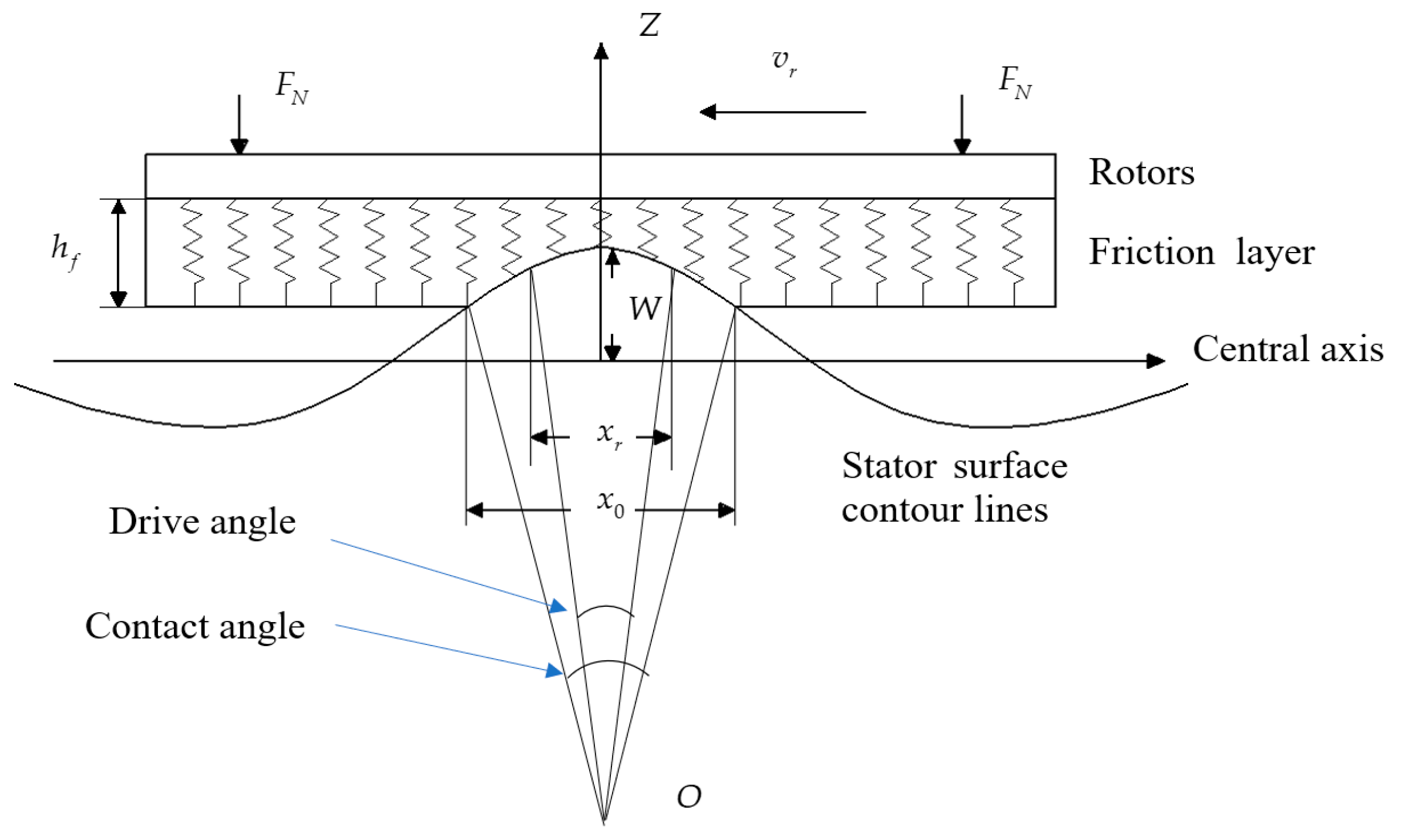
The contact interface has three variables that need to be analyzed. The first is the contact length , which is the circumferential distance between the two ends of the contact zone. A contact zone is a set for all the contact points in a single wave crest. This distance would change with the wave traveling so it may be written as . Similarly, we can define the second parameter. The drive length is the circumferential distance between the two equivalence speed points and can be written as . The equivalence speed point is the dividing point between the drive zone and hindrance zone. On these two points, the friction surface micro mass and the overall rotor have the same circumferential speed. The last one is the amplitude of the stator surface mass. Figure 1 shows a simplified diagram of the stator–rotor contact interface.
The relationship between the feedback voltage and amplitude can be expressed as follows [23]:
where is the feedback voltage; is the conversion factor of the feedback voltage to amplitude.
The angular speed coefficient could be calculated by the modal mass and the modal stiffness as follows. The relative damper ratio can be written as the function of these two parameters too.
where is the angular velocity at the resonant frequency with zero preload; is the modal damping of the stator.
The equivalent stiffness factor of the friction layer is:
where , and are the modulus of elasticity, radial contact width and thickness of the friction layer.
When preload is applied, the relationship between contact distance and preload can be expressed as:
where contact length is .
The second-order dynamics model of the motor can be expressed as [24]:
where is the drive voltage.
Apply Equation (5) into Equation (6), which gives:
Take as the additional stiffness of the stator.
The following equation is obtained:
where is the electromechanical coupling coefficient; is the force coefficient affecting the amplitude.
When the drive voltage, drive frequency and preload are given, the contact length can be obtained by Equation (9).
The output torque can be calculated from the contact distance as follows:
where is the rotor radius; is the coefficient of friction.
When the preload and the contact distance are certain, the output torque is zero and the drive length can be obtained [25].
The tangential velocity at the stator surface can be expressed as:
where is the distance from the stator tooth surface to the neutral plane.
When a certain amount of preload is applied, the amplitude can be expressed as:
2.2. Efficiency Model
Ultrasonic motors generate various forms of energy losses during operation. The losses include the piezoelectric sheet wear, the damping loss due to stator vibration, and the friction loss at the contact interface. In the contact model, the contact angle is derived from the measured preload and feedback voltage, and the contact angle will be used directly as input parameters to the efficiency model.
The loss in piezoelectric sheets mainly includes dielectric loss, damping loss and electromechanical loss, in which the dielectric loss accounts for the largest proportion. As the piezoelectric sheet is pasted on the stator ring, the piezoelectric ceramic and stator ring can be used as a composite structure of the stator when considering the damping loss. The electromechanical loss may be neglected due to their small values.
The tangent to the dielectric loss angle can be expressed as the following equation:
where is the static capacitance and is the equivalent resistance of the dielectric.
The dielectric loss over one drive voltage cycle can be expressed as:
where is the load-bearing equivalent resistance; is the drive voltage period.
The piezoelectric sheet generates damping losses under high-frequency vibrations and the stator ring undergoes forced vibrations under the excitation of the piezoelectric sheet. Here the stator ring and piezoelectric sheet are used as a composite structure. The damping loss of the composite structure can be expressed as the following equation.
where and are the equivalent Young’s modulus of the stator ring and piezoelectric sheet respectively; and are the cross-sectional moments of inertia of the two respectively; and are the damping coefficients of the two respectively. The variable of the second-order partial is expressed as the position on the stator structure.
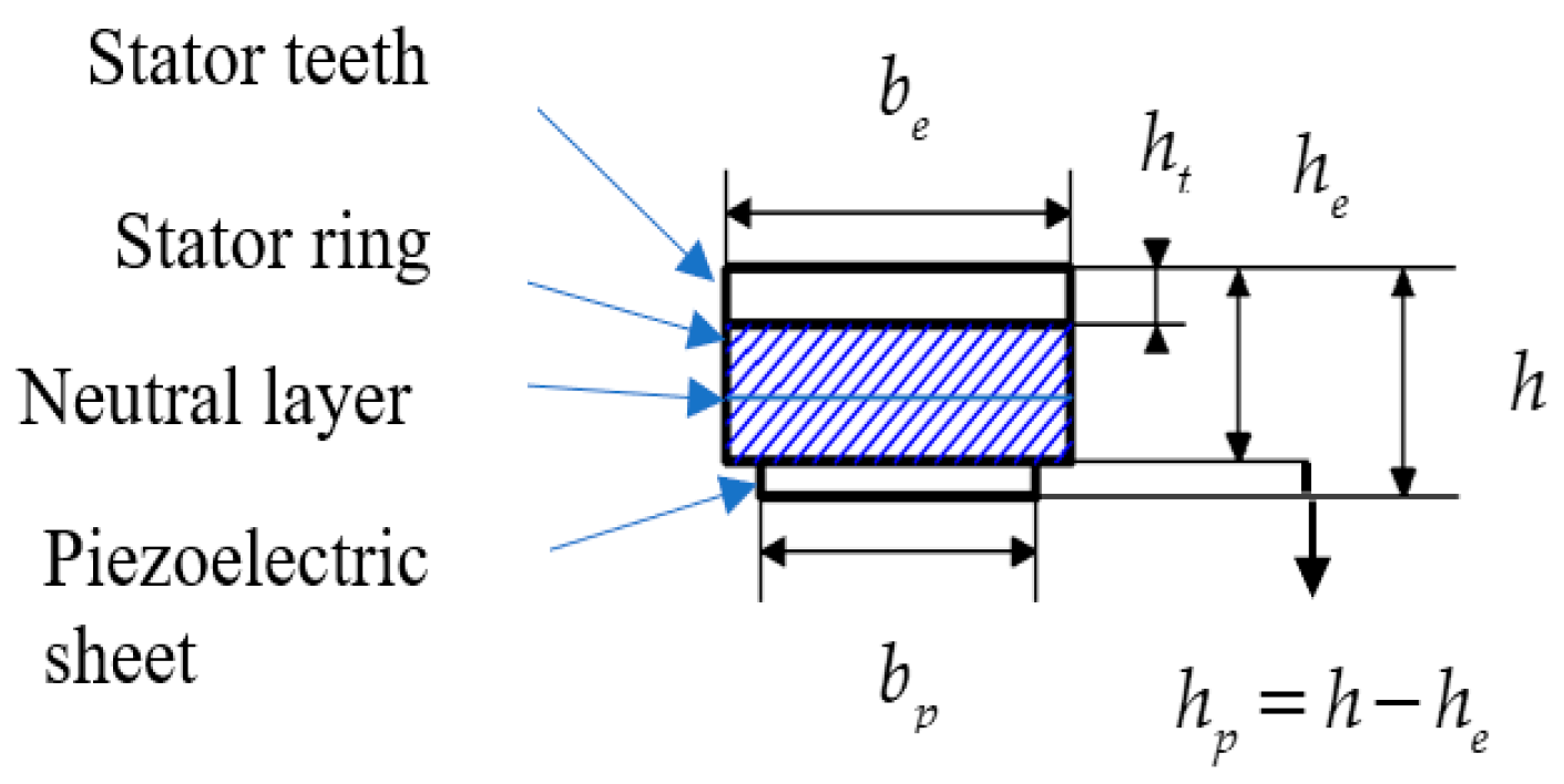
The diagram below shows the schematic of piezoelectric composite structure.
In Figure 2, the width of the stator ring and stator ring is . The height of the stator teeth is . The height of the stator ring plus stator teeth is . The stator height is and the width of the piezoelectric ring is .
The cross-sectional moment of inertia of the stator ring and piezoelectric sheet can be expressed as:
where is the distance from the upper surface of the stator ring to the neutral layer. The neutral layer is illustrated in Figure 2.
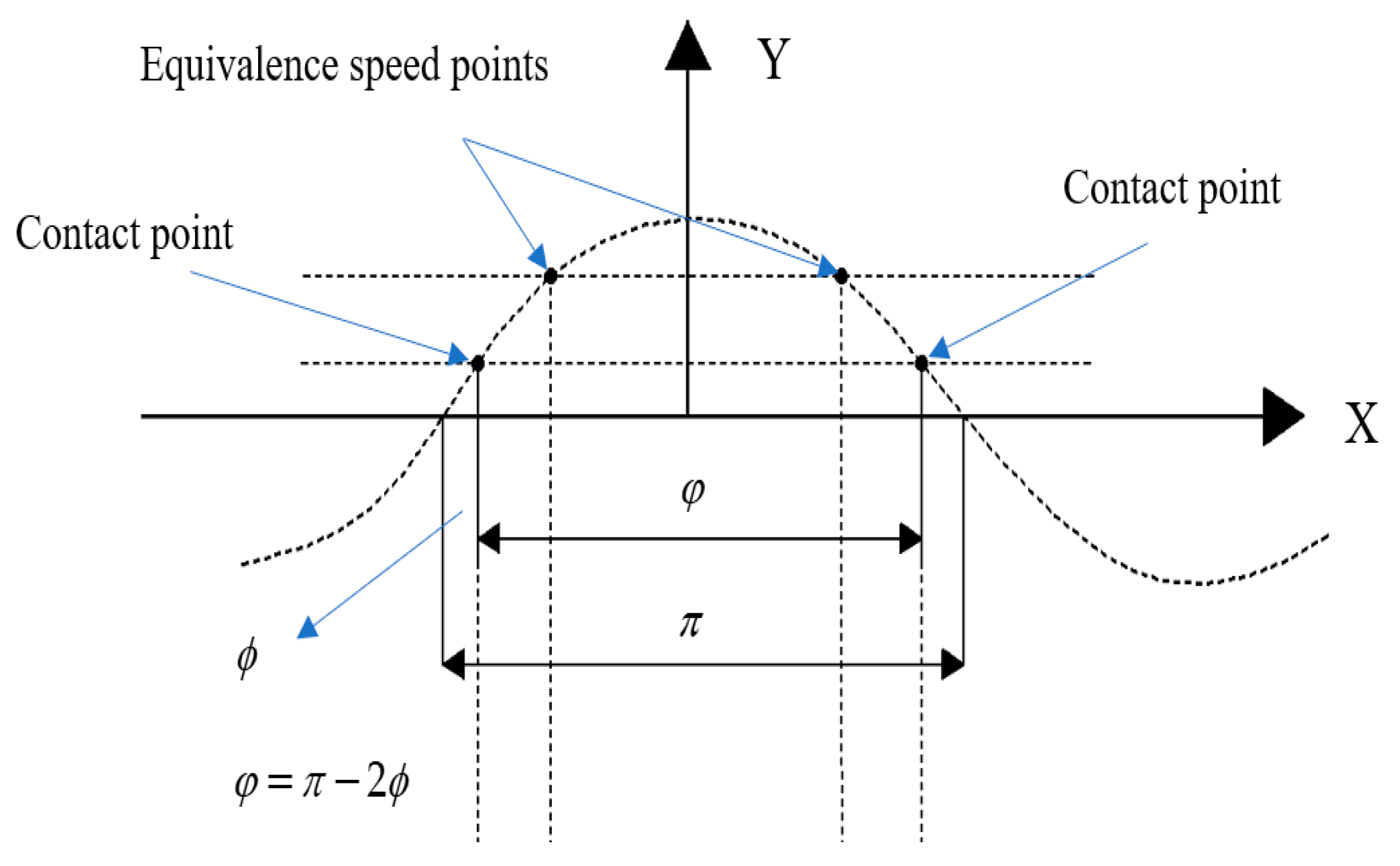
Figure 3 illustrates the parameters of the contact model during a traveling wave period. The contact model gives a radian from the contact length , which is calculated on the measured preload and feedback voltage in Section 2.1. is half of the range except for the contact zone. Then, we can get .
The frictional energy loss at the contact interface during a drive voltage cycle can be expressed as:
where is the proportionality constant reflecting the magnitude of the frictional force; is the tangential velocity of the wave crest mass on the surface of the stator traveling wave. is the rotor speed. is the velocity of the surface mass of the traveling wave.
The four coefficients in Equation (21) can be expressed as:
The output energy of the motor during one drive voltage cycle is:
where is the load torque; is the rotor angular speed.
The output efficiency of the model was obtained as:
It is quite difficult to measure the three energy losses , and . Thus, we count the efficiency directly by the ratio between the input and output energies. The input energy of the motor during one drive voltage cycle is:
The experimentally measured output efficiency of the motor can be expressed as:
3. Simulation and Experimentation
In order to verify the above model, we build a simple test rig for an ultrasonic motor.
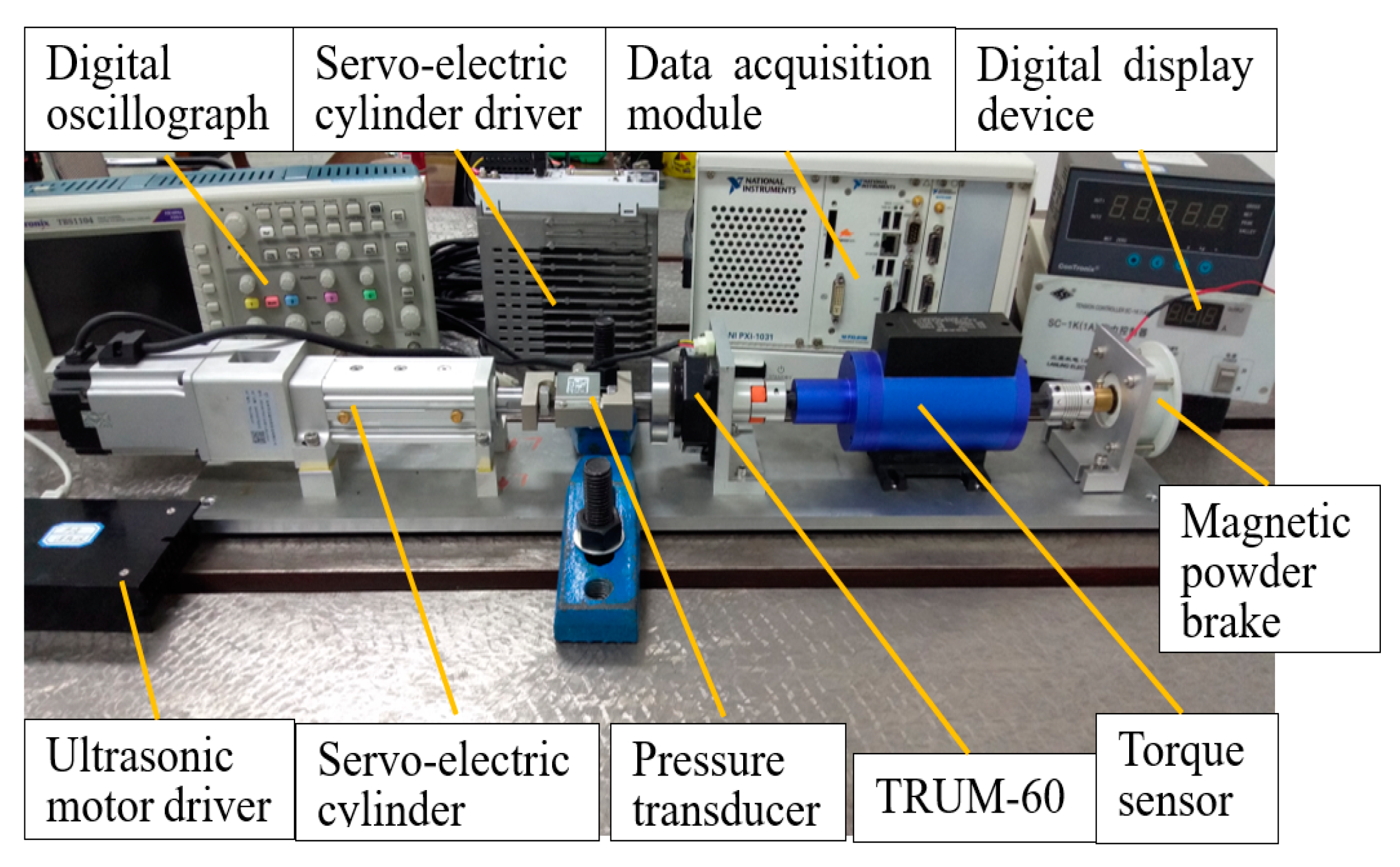
As shown in Figure 4. The TRUM-60 was driven by an ultrasonic motor driver. The preload was provided by a servo-electric cylinder (DDA-40, Dingying Intelligent Equipment Co., Ltd., Shenzhen, China). The servo-electric cylinder is driven by an actuator. A pressure transducer (TSC-1000, Toledo Corporation, Shanghai, China) sensed the preload and generated a force signal which was displayed by a digital display device. Torque sensor (CYT-303, Tianyu Hengchuang Sensor Technology Co., Ltd., Beijing, China) with data acquisition module (PXI-1031, NI, Austin, TX, USA) can record motor speed, torque and power signals. The tension controller (SC-1K, Lanling Mechanical and Electrical Technology Co., Ltd., Jiangsu, China) provides a stable current input to the magnetic powder brake (FKG-10, Lanling Mechanical and Electrical Technology Co., Ltd., Jiangsu, China). The magnetic powder brake provided a simulated load for the TRUM-60. The digital oscilloscope is used to measure the electrical signal of the ultrasonic motor.
This section analyses the drive characteristics and simulates the contact and output efficiency models, and verifies the validity of the output efficiency model through experiments.
3.1. Drive Characteristics
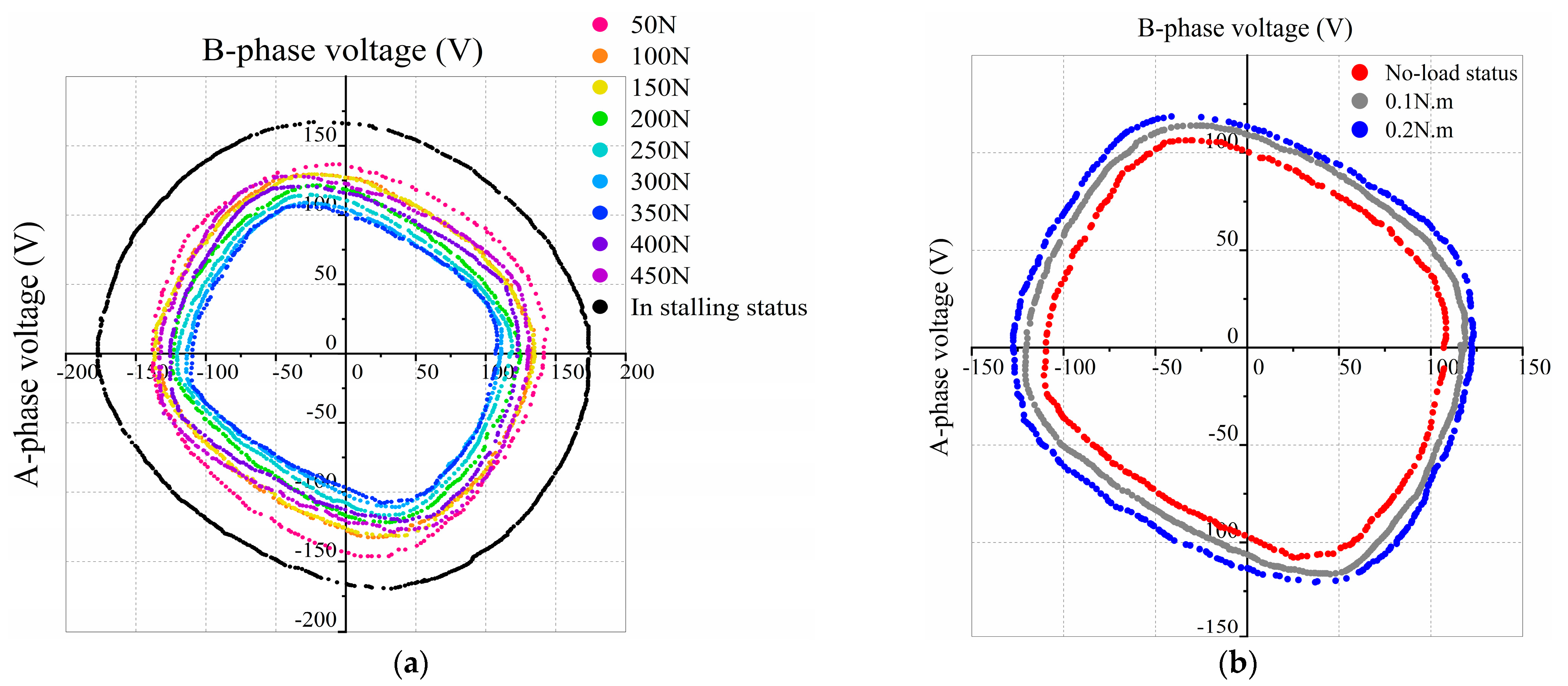
This section investigates the drive characteristics of the motor, using experiments to measure the effect of different preload on the two-phase drive voltage and input current. The results are shown in Figure 5.
The drive frequency is 42 kHz. As can be seen from Figure 5a, when the motor is at no load and the preload increases from 50 N to 300 N, the two-phase drive voltage amplitude gradually decreases, but the magnitude of the decrease is not obvious and is reflected in the Lissajous curve, where the enclosed zone gradually decreases and reaches a minimum at 350 N. When the preload reaches 350 N, the A-phase drive voltage amplitude decreases to 110 V and 112 V in the opposite directions. The B-phase drive voltage amplitude decreases to 101 V and 96 V in the opposite directions. The four voltage amplitudes have an average value of 106 V, which is 35 V less than the average value at 50 N. As the preload continues to increase, the two-phase voltage amplitude begins to increase again. Too much voltage difference between phase A and phase B will damage the amplitude stability of the traveling waves. If this situation happened, the stator surface mass of the elliptical motion trajectory would distort, causing unstable operations due to a poor contact state. Figure 5b shows that when the preload is 350 N and drive frequency is 42 kHz, the amplitude of the drive voltage increases as the load increases. Therefore, it can be summarized from the above two figures that, for the drive voltage without any load, an increase in preload will result first in a decrease and then an increase. When the motor has a certain preload, the drive voltage will increase with the load.
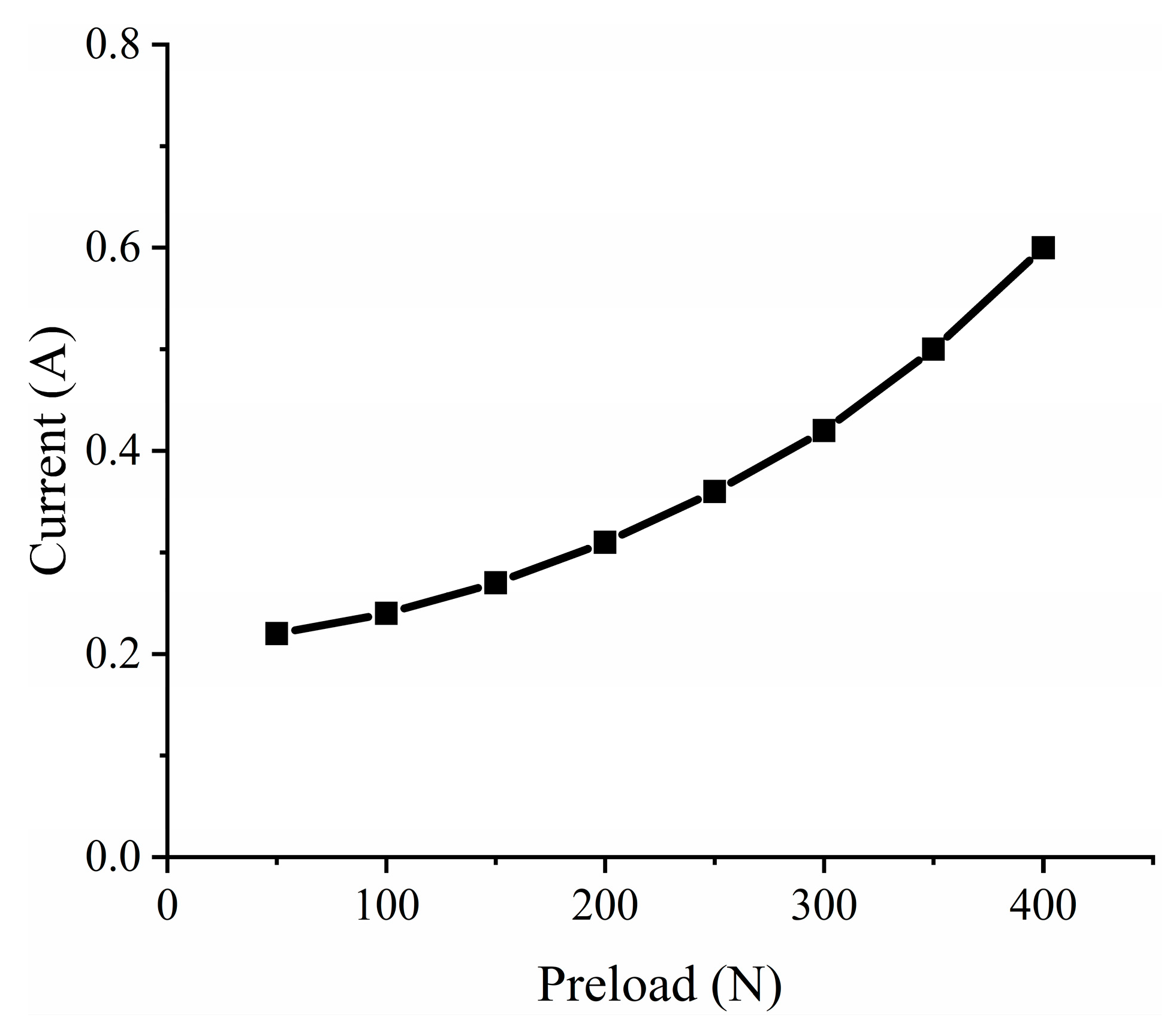
The drive frequency is 42 kHz. The load is zero. Figure 6 shows that as the preload increases, the current increases exponentially. The minimum current is 0.22 A at 50 N preload, When the preload is 400 N the maximum current is 0.6 A.
The input power is equal to the drive voltage multiplied by the input current, both the drive voltage and the input current vary with preload. Therefore, an increase in the preload or in the load will result in an increasing the energy input to the motor.
3.2. Contact Characteristics
The no-load speed and feedback voltage were collected at different preloads. Then we fitted these data with reference to the literature [22]. The motor identification parameters are shown in Table 1. The relevant performances were measured and listed in Table 2.
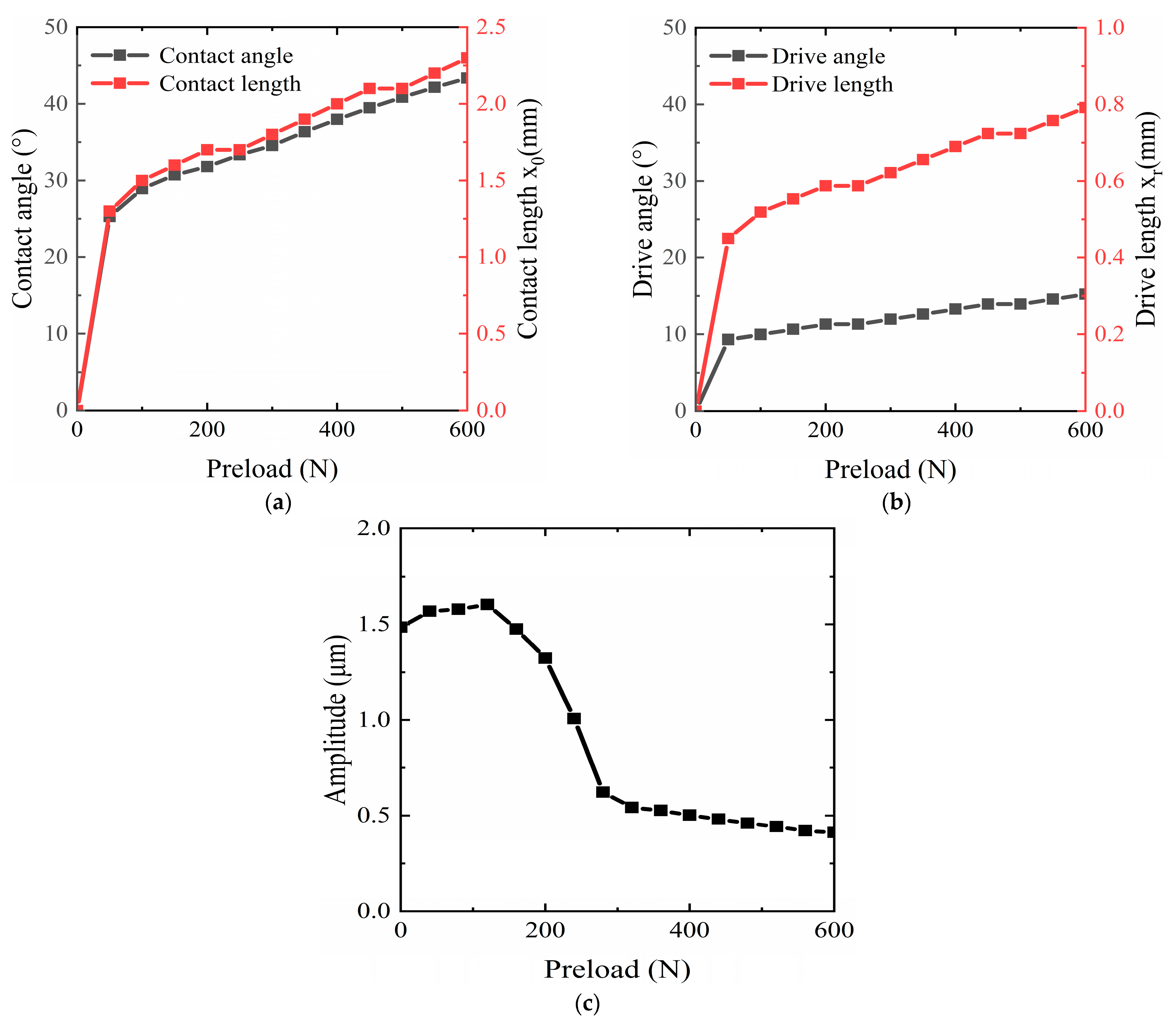
Putting the above conversion factors into the contact model, we can obtain the variation of the contact interface within a wave lengths. Five characterristc curves, including the contact angle and length, the drive angle and the length, and the amplititude, are shown in Figure 7.
In Figure 7a, the drive frequency is 42 kHz and the drive voltage is 150 V. The contact length increases rapidly as the preload increases from zero. As the preload increases to 50 N, the growth of the contact length begins to slow down. The growth rate is approximately 1.8 × 10⁻³ mm/N until the contact length gradually reaches a quarter of the wavelength. The trend of the contact angle is similar to that of the contact length.
In Figure 7b, the trend of the drive angle and length are similar to that of the contact length. However, they are much less than the contact angle and length.
Figure 7c shows the relationship between amplitude and preload. The amplitude increases slightly when the preload is 0 N–100 N and decreases rapidly when it is greater than 100 N until the preload increases to 300 N. After that, the amplitude begins to decrease more slowly.
The above shows that there is a drive and hysteresis zone at the contact interface. The size of these drive two zones is non-linear, and the tooth structure on the stator will directly exacerbate this non-linear effect.
3.3. Efficiency Features
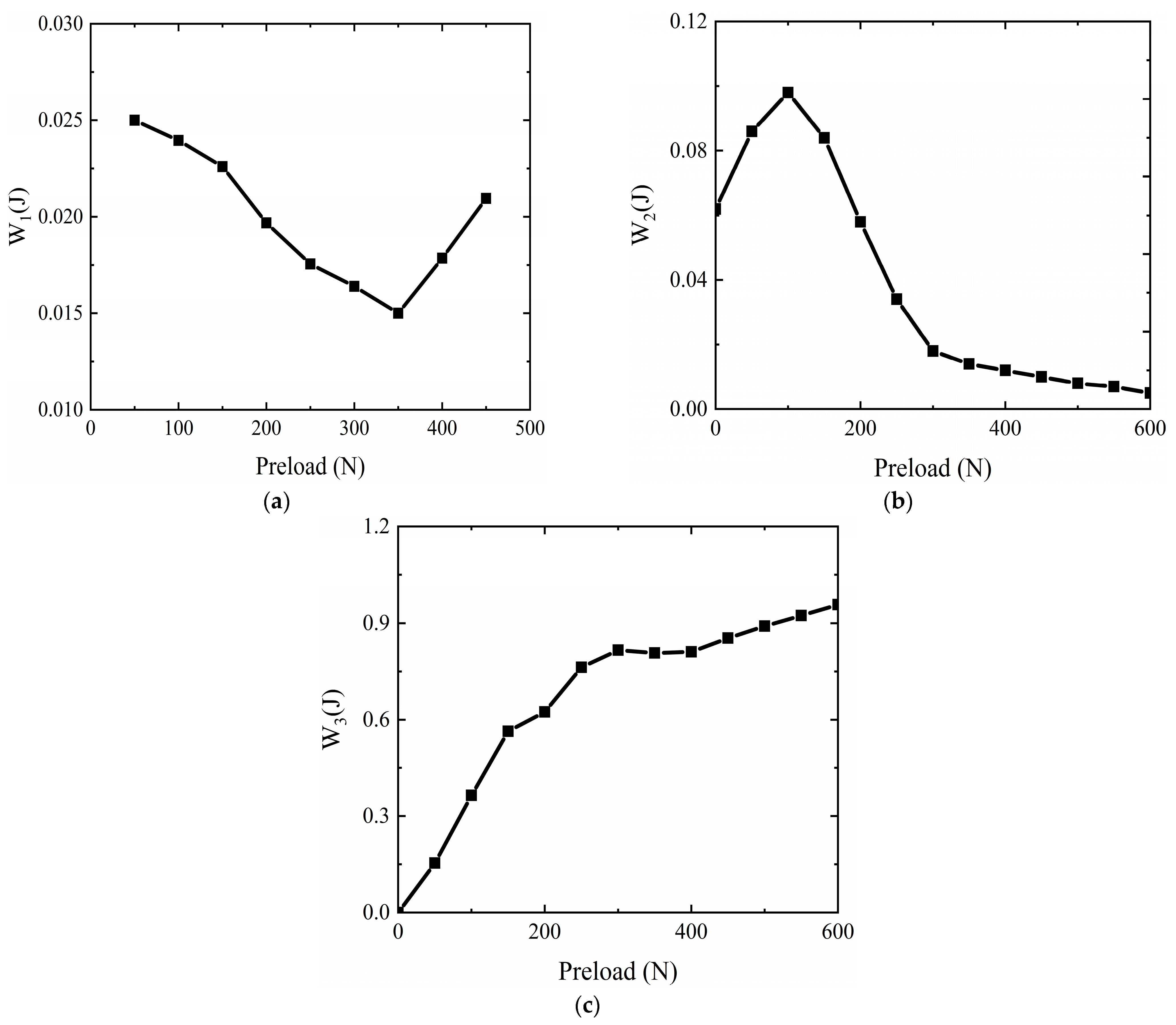
The output efficiency model was simulated to obtain three energy losses in one traveling wave cycle. The simulation curves are shown in Figure 8.
From Figure 8a, the dielectric loss is defined by the drive voltage and the electrical parameters. The drive voltage is influenced by preload. Based on the results in Section 3.1, we can find that the dielectric loss follows a similar trend to the drive voltage with preload. Dielectric loss decreases and then increases with preload. Losses are minimized when the pre-pressure reaches 350 N. Figure 8b shows that the damping loss of the composite stator follows a similar trend to the variation of amplitude with preload. It keeps increasing in the range 0–100 N. When the preload is 100 N–300 N, the damping loss decreases rapidly. After that, the decrease slows down and tends to 5 × 10⁻³ J. This is because the energy loss in material bending is proportional to the square of the vibration amplitude, the bending stiffness and bending angle, according to Equation (17). Figure 8c shows that the frictional losses will increase with increasing preload.
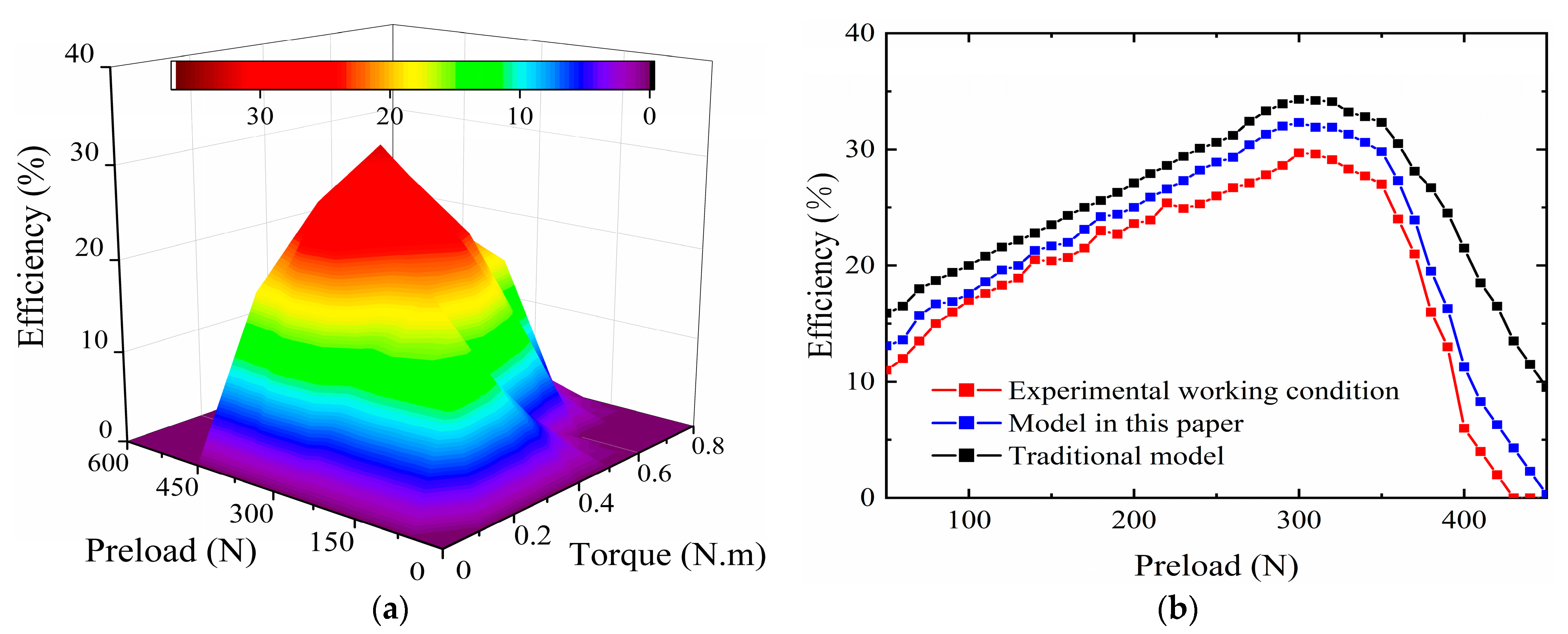
Figure 9a shows the efficiency’s overall map with the preload and output torque. The driving frequency is 42 kHz. The drive voltage is 150 V. The output efficiency’s 3D surface basically maintains the trend of increasing and then decreasing. We choose a typical 0.2 N.m torque and illustrated the simulation and experimental result in Figure 9b. A simulation curve with the traditional model is added for comparison. The driving frequency is 42 kHz. The drive voltage is 150 V. The experimental curve is below the simulation curve of the new model for two main reasons: firstly, the efficiency model is built with more simplifications, simplifying the stator ring with teeth to a simply supported beam, resulting in smaller stator damping losses than the actual losses; compared to the 3D contact model, the contact interface is simplified to a 2D contact model, and no radial sliding losses are considered. Secondly, only three relatively large energy losses are considered in the efficiency model, and other loss types are not accounted into simulations.
It can be seen from Figure 9b that the efficiency model in this paper has a higher correlation than the traditional efficiency model [26]. The Pearson correlation coefficient between the traditional efficiency model and the real working condition of the motor is 0.925, while for the new model it is 0.991.
4. Conclusions
In this paper, a contact model and efficiency model based on measured preload and feedback voltages are presented. The contact interface parameters and output efficiency of the ultrasonic motor are analyzed by measuring the preload and feedback voltage in real-time. Through the simulations and test experiments, the following conclusions are obtained:
- (1)
- The proposed new model could offer more accurate interface variables by real-time identifications. The composite stator structure allows us to calculate the output performance more easily. Comparing with the traditional model, the Pearson correlation coefficient with real operating conditions increases from 0.925 to 0.991. A higher Pearson coefficient may lead to a better quality for simulations.
- (2)
- The simulation results of the contact model show that the proportion of the drive zone to the contact zone gradually decreases with the preload. The stator surface mass vertical amplitude first increases and then decreases. The amplitude keeps a larger value when the preload is within 200 N. The maximum amplitude is 1.6 microns when the preload is 120 N.
- (3)
- By the motor drive characteristics test, we found that when the motor is in the no-load state, the drive voltage first decreases and then increases with the preload increases. When the load increases from zero to 0.2 N.m, the drive voltage gradually increases with a constant preload. For a constant load, the input current and the input energy will also increase with the preload.
- (4)
- The friction loss, increasing with the preload, accounts for the largest proportion of the three kinds of losses. As to the stator damping loss, the amplitude of the stator surface mass plays a very important role, which reaches its peak when the preload is about 100 N.
Author Contributions
Conceptualization, H.S. and H.Y.; methodology, H.S.; software, H.S.; validation, H.S., H.Y. and J.L.; formal analysis, H.Y.; writing—original draft preparation, H.S.; writing—review and editing, H.S.; supervision, X.Z.; project administration, H.Y.; funding acquisition, J.L. All authors have read and agreed to the published version of the manuscript.
Funding
This research was funded by National Natural Science Foundation of China (51575288) and Natural Science Foundation of Shandong Province General Project (ZR2019MEE089).
Conflicts of Interest
The authors declare no conflict of interest.
References
- Pulskamp, J.S.; Polcawich, R.G.; Rudy, R.Q.; Bedair, S.S.; Proie, R.M.; Ivanov, T.; Smith, G.L. Piezoelectric PZT MEMS technologies for small-scale robotics and RF applications. MRS Bull. 2012, 37, 1062–1070. [Google Scholar] [CrossRef]
- Feng, Z.; Liang, W.; Ling, J.; Xiao, X.; Tan, K.K.; Lee, T.H. Integral terminal sliding-mode-based adaptive integral backstepping control for precision motion of a piezoelectric ultrasonic motor. Mech. Syst. Signal Process. 2020, 144, 106856. [Google Scholar] [CrossRef]
- Takemura, K.; Park, S.; Maeno, T. Control of multi-dof ultrasonic actuator for dexterous surgical instrument. J. Sound Vib. 2008, 311, 652–666. [Google Scholar] [CrossRef]
- Lau, J.Y.; Liang, W.; Liaw, H.C.; Tan, K.K. Sliding Mode Disturbance Observer-based Motion Control for a Piezoelectric Actuator-based Surgical Device. Asian J. Control. 2018, 20, 1194–1203. [Google Scholar] [CrossRef]
- Wang, W.; Castro, L.A.; Hoyos, M.; Mallouk, T. Autonomous Motion of Metallic Microrods Propelled by Ultrasound. ACS Nano 2012, 6, 6122–6132. [Google Scholar] [CrossRef]
- Smith, G.L.; Pulskamp, J.S.; Sanchez, L.M.; Potrepka, D.; Proie, R.M.; Ivanov, T.G.; Rudy, R.Q.; Nothwang, W.D.; Bedair, S.S.; Meyer, C.D.; et al. PZT-Based Piezoelectric MEMS Technology. J. Am. Ceram. Soc. 2012, 95, 1777–1792. [Google Scholar] [CrossRef]
- Li, J.; Zhao, H.; Qu, H.; Cui, T.; Fu, L.; Huang, H.; Ren, L.; Fan, Z. A piezoelectric-driven rotary actuator by means of inchworm motion. Sens. Actuators A Phys. 2013, 194, 269–276. [Google Scholar] [CrossRef]
- Mashimo, T. Micro ultrasonic motor using a one cubic millimeter stator. Sens. Actuators A Phys. 2014, 213, 102–107. [Google Scholar] [CrossRef]
- Ho, S.-T.; Jan, S.-J. A piezoelectric motor for precision positioning applications. Precis. Eng. 2016, 43, 285–293. [Google Scholar] [CrossRef]
- Mashimo, T.; Iduhara, S.; Arai, S.; Zhang, Z.; Oku, H. High-Speed Visual Feedback Control of Miniature Rotating Mirror System Using a Micro Ultrasonic Motor. IEEE Access 2019, 8, 38546–38553. [Google Scholar] [CrossRef]
- Mashimo, T. Miniature preload mechanisms for a micro ultrasonic motor. Sens. Actuators A Phys. 2017, 257, 106–112. [Google Scholar] [CrossRef]
- Storck, H.; Wallaschek, J. The effect of tangential elasticity of the contact layer between stator and rotor in travelling wave ultrasonic motors. Int. J. Non-Linear Mech. 2003, 38, 143–159. [Google Scholar] [CrossRef]
- Shen, S.; Lee, H.P.; Lim, S.P.; Ong, C.J. Three-dimensional finite element analysis of interfacial delamination in traveling wave ultrasonic motors. Int. J. Damage Mech. 2014, 23, 964–978. [Google Scholar] [CrossRef]
- Ren, W.; Yang, L.; Ma, C.; Li, X.; Zhang, J. Output performance simulation and contact analysis of traveling wave rotary ultrasonic motor based on ADINA. Comput. Struct. 2019, 216, 15–25. [Google Scholar] [CrossRef]
- Ran, L.; Zhou, W.; He, J.; Zhan, L.; Chen, Q.; Yu, H.; Peng, B. A novel three-dimensional contact model of piezoelectric traveling wave ultrasonic micromotor. Smart Mater. Struct. 2020, 29, 075016. [Google Scholar] [CrossRef]
- Mashimo, T.; Terashima, K. Dynamic analysis of an ultrasonic motor using point contact model. Sens. Actuators A Phys. 2015, 233, 15–21. [Google Scholar] [CrossRef]
- Radi, B.; El Hami, A. The study of the dynamic contact in ultrasonic motor. Appl. Math. Model. 2010, 34, 3767–3777. [Google Scholar] [CrossRef]
- Renteria-Marquez, I.; Tseng, B.T.L. A novel contact model of piezoelectric traveling wave rotary ultrasonic motors with the finite volume method. Ultrasonics 2018, 90, 5–17. [Google Scholar] [CrossRef]
- Zhang, J.; Yang, L.; Ma, C.; Ren, W.; Zhao, C.; Wang, F. Improving efficiency of traveling wave rotary ultrasonic motor by optimizing stator. Rev. Sci. Instrum. 2019, 90, 056104. [Google Scholar] [CrossRef]
- Liu, J.; Niu, R.; Zhu, H.; Zhao, C. Improving the efficiency of a hollow ultrasonic motor by optimizing the stator’s effective electromechanical coupling coefficient. Rev. Sci. Instrum. 2020, 91, 016104. [Google Scholar] [CrossRef]
- Wang, G.Q. Research on Several Key Problems of Traveling-wave Type Ultrasonic Motor. Ph.D. Thesis, Zhejiang University, Hangzhou, China, March 2006. [Google Scholar]
- Li, S.; Li, D.; Yang, M.; Cao, W. Parameters identification and contact analysis of traveling wave ultrasonic motor based on measured force and feedback voltage. Sens. Actuators A Phys. 2018, 284, 201–208. [Google Scholar] [CrossRef]
- Giraud, F.; Lemaire-Semail, B.; Aragones, J.; Robineau, J.; Audren, J.-T. Stability Analysis of an Ultrasonic Motor for a New Wave Amplitude Control. In Proceedings of the 2007 IEEE Industry Applications Annual Meeting, New Orleans, LA, USA, 23–27 September 2007; Volume 45, pp. 1343–1350. [Google Scholar] [CrossRef] [Green Version]
- Zhu, M. Contact analysis and mathematical modeling of traveling wave ultrasonic motors. IEEE Trans. Ultrason. Ferroelectr. Freq. Control. 2004, 51, 668–679. [Google Scholar] [CrossRef] [PubMed] [Green Version]
- Guo, J.; Gong, S.; Guo, H.; Liu, X.; Ji, K. Force transfer model and characteristics of hybrid transducer type ultrasonic motors. IEEE Trans. Ultrason. Ferroelectr. Freq. Control. 2004, 51, 387–395. [Google Scholar] [CrossRef] [PubMed]
- Dong, Z.P. Traveling Ultrasonic Motors baesd on Effective Elliptic Motion and Structural Force Factor. Ph.D. Thesis, Hefei University of Technology, Hefei, China, July 2015. [Google Scholar]
Figure 1.
Model drawing of a wire spring at the stator–rotor contact interface.

Figure 2.
Schematic of piezoelectric composite structure.

Figure 3.
Schematic diagram of the contact model.

Figure 4.
Diagram of ultrasonic motor experimental device.

Figure 5.
Variation of two-phase drive voltage with preload: (a) No-load status; (b) Different load states at a preload of 350 N.
Figure 5.
Variation of two-phase drive voltage with preload: (a) No-load status; (b) Different load states at a preload of 350 N.

Figure 6.
Current variation at different preloads.

Figure 7.
Contact interface parameters for no-load conditions at different preloads: (a) Contact length and contact angle; (b) Drive length and drive angle; (c) Amplitude.
Figure 7.
Contact interface parameters for no-load conditions at different preloads: (a) Contact length and contact angle; (b) Drive length and drive angle; (c) Amplitude.

Figure 8.
Three types of energy loss versus preload for one travelling wave period: (a) Dielectric loss ; (b) Damping loss ; (c) Frictional loss .
Figure 8.
Three types of energy loss versus preload for one travelling wave period: (a) Dielectric loss ; (b) Damping loss ; (c) Frictional loss .

Figure 9.
Motor output efficiency: (a) Experimental results of preload–load torque–output efficiency; (b) Comparison of output efficiency for a load torque of 0.2 N.m.
Figure 9.
Motor output efficiency: (a) Experimental results of preload–load torque–output efficiency; (b) Comparison of output efficiency for a load torque of 0.2 N.m.


Table 1.
Motor identification parameters.
| Motor Identification Parameters | Value |
|---|---|
| (m) | |
Table 2.
Contact model parameter.
| Preload (N) | No-Load Speed (rpm) | Feedback Voltage (V) | Conversion Factor |
|---|---|---|---|
| 100 | 106 | 38 | 3.07 × 10⁷ |
| 200 | 144 | 46 | 3.24 × 10⁷ |
| 300 | 138 | 40 | 3.11 × 10⁷ |
| 400 | 89 | 34 | 2.86 × 10⁷ |
Publisher’s Note: MDPI stays neutral with regard to jurisdictional claims in published maps and institutional affiliations. |
© 2021 by the authors. Licensee MDPI, Basel, Switzerland. This article is an open access article distributed under the terms and conditions of the Creative Commons Attribution (CC BY) license (https://creativecommons.org/licenses/by/4.0/).
Share and Cite
MDPI and ACS Style
Sun, H.; Yin, H.; Liu, J.; Zhang, X. Efficiency Model for Traveling Wave-Type Ultrasonic Motors Based on Contact Variables and Preload. Actuators 2021, 10, 158. https://0-doi-org.brum.beds.ac.uk/10.3390/act10070158
AMA Style
Sun H, Yin H, Liu J, Zhang X. Efficiency Model for Traveling Wave-Type Ultrasonic Motors Based on Contact Variables and Preload. Actuators. 2021; 10(7):158. https://0-doi-org.brum.beds.ac.uk/10.3390/act10070158
Chicago/Turabian StyleSun, Haoyu, Hao Yin, Jiang Liu, and Xilong Zhang. 2021. "Efficiency Model for Traveling Wave-Type Ultrasonic Motors Based on Contact Variables and Preload" Actuators 10, no. 7: 158. https://0-doi-org.brum.beds.ac.uk/10.3390/act10070158
Note that from the first issue of 2016, this journal uses article numbers instead of page numbers. See further details here.