Analysis of Collapse Mechanism and Treatment Evaluation of a Deeply Buried Hard Rock Tunnel


1
Department of Civil Engineering, Central South University, Changsha 410075, China
2
Department of Geotechnical Engineering, Tongji University, Shanghai 200092, China
*
Author to whom correspondence should be addressed.
Appl. Sci. 2020, 10(12), 4294; https://0-doi-org.brum.beds.ac.uk/10.3390/app10124294
Submission received: 27 May 2020
/
Revised: 10 June 2020
/
Accepted: 11 June 2020
/
Published: 23 June 2020
(This article belongs to the Special Issue Seismic Geotechnical Hazards Studies)
Abstract
:Collapse is one of the most dangerous geological disasters in tunnel construction, and it is an urgent engineering problem which needs to be solved. Taking the collapse of the top of an actual tunnel face as an example, through field investigation and theoretical calculation methods, the mechanism of tunnel collapse was studied, and the treatment and evaluation of the collapse area were proposed based on field monitoring data. The results show that the extrusion and bulging deformation on the palm surface and the tensile fracture in the top inclined stratum led to the shear slip of the block along the structural surface and the local collapse of the surrounding rock. Based on the block theory, the potential unstable block at the top of the tunnel was successfully identified, and the treatment method of ‘protecting before filling and then digging’ was proposed. The comprehensive treatment measures of advance bolts, steel arch support, collapse backfill, and step excavation were adopted, with on-site monitoring followed up step by step. Based on the analysis of surrounding rock deformation and stress characteristics, in this paper we demonstrate that the treatment effects of the collapse area are good, and ensure the safety and smooth progress of construction. The proposed treatment method achieved the expected goal and was shown to be able to provide successful treatment for similar collapse cases of tunnel engineering.
1. Introduction
Geological disasters such as collapses, water inrush, and landslides are thorny problems in engineering construction [1,2,3]. The process of tunnel construction, due to the complex geological environment along the line and the geological uncertainty in front of the face, is often faced with engineering disasters such as collapses, water inrush, and large deformations, which seriously affect the safety of workers and the tunnel construction. Therefore, it is necessary to provide valuable engineering experience of tunnel collapse accidents based on the mechanism and treatment evaluation of incidents of tunnel collapse in specific environments. At present, scholars at home and abroad have done a lot of research on tunnel collapse and made significant breakthroughs. Based on data drawn from a large number of tunnel collapse cases, Shin et al. [4] proposed four different collapse failure mechanisms, namely, blasting induction, groundwater action, geological environment, and the excavation method. Yang et al. [5,6,7] analyzed the collapse mechanism of deep and shallow buried tunnels from different perspectives, such as the correlation flow law and failure criterion. According to the centrifuge test and discrete element method carried out by Osman et al. [8], Wang et al. [9], Mete et al. [10] and Zhou et al. [11], the mechanism of shallow tunnel collapse disasters has been thoroughly studied through theoretical analysis. Zheng et al. [12] studied the mechanism of tunnel collapse based on model tests and the influence of the arch effect and water inrush on a lining structure using numerical simulation methods. Huang et al. [13] analyzed the collapse mechanism of a karst tunnel and calculated the safe thickness of the rock column, which is close to the numerical analysis results. Based on the Hoek Brown criterion, Fraldi and Guarracino et al. [14,15] proposed a comprehensive analytical solution for the tunnel collapse mechanism considering an arbitrary excavation profile; a case study was selected to reveal the progressive failure evolution law of tunnel collapse using the proposed solution and other numerical methods. Salvador and Rafael [16] have studied the failure mechanism of the working face of in layered soil due to local collapse through numerical simulations. Based on a statistical analysis of a large number of tunnel collapse cases, Wang et al. [17] proposed that tunnel depth, groundwater, surrounding rock level, and construction measures were the main factors affecting tunnel collapse; the influence of rainfall conditions on tunnel collapse was also studied through model tests, which indicated that groundwater has a significant impact on tunnel collapse. According to Zhang et al. [18], the main factors in a tunnel collapse are groundwater infiltration and the construction method, and four quick remedial measures of backfilling, reinforcement, grouting and drainage have been put forward. Li et al. [19] discussed the influence of the interface, hydrogeology and advanced geological prediction on the collapse of the tunnel and established a tunnel information monitoring management system. According to the causes of tunnel collapse, the combined treatment measures of pipe shed and grouting reinforcement, grouting and lining reinforcement, etc. were put forward [20,21,22,23]. Chen et al. [24,25] and Wu [26] evaluated and analyzed the treatment effect of tunnel collapse section by combined numerical simulation with on-site monitoring. Close range photography and remote sensing technology provide the possibility of structural surface measurement in tunnel monitoring [27,28,29,30]. Zuo et al. [31] analyzed the factors influencing collapse and the instability mode of surrounding rock for tunnels crossing the fault zone with water rich soft rock and proposed joint treatment measures for inside and outside the tunnel. Wang et al. [32] analyzed the collapse process and instability mechanism of a slate tunnel, and summarized the collapse prevention experience from the survey, design and construction stages. Based on catastrophe theory, Zuo et al. [33] predicted the possibility of tunnel collapse and proposed corresponding preventive measures. Zhang et al. [34] studied the mechanism of tunnel collapse and established the risk assessment system for mountain tunnel collapse. Prasad et al. [35] proposed a new algorithm of tunnel structural support pressure to evaluate the stability of surrounding rock based on the key block theory. Based on the block theory, Zhang et al. [36,37] studied the influence of interaction between cutting tools and rock blocks on the stability of TBM shield tunneling face. Jiang, A. and Jin, L.F. [38] and Li, X. et al. [39] have applied support vector machine (SVM) methods to analyze and evaluate the stability of the surrounding rock of a tunnel. To sum up, the research on tunnel collapse in China and elsewhere has accumulated a lot of valuable experience and put forward many effective collapse prevention and treatment techniques. However, current research mainly focuses on the mechanism and influencing factors for the collapse of tunnels at a shallow depth, in soft rock, rich water, and other adverse geological conditions, while few studies have reported on the collapse of deeply buried hard rock tunnels. Due to the regional differences in tunnel construction, the reasons and scale of tunnel collapse are also different, so it is difficult to implement countermeasures systematically, and more of them still rely on engineering experience. Therefore, the Chen Jiashan tunnel was selected as a case study to analyze the arch collapse during the construction of the deeply buried section. Base on comprehensive analysis of the geological conditions, collapse characteristics and types, and the construction environment, the collapse mechanism was analyzed. Based on block theory, the stability of the key block was analyzed and predicted, which provided important information for further treatments. Finally, monitoring results were applied to evaluate the treatment quality of collapse area. The proposed method could provide engineering experience for similar projects.
2. Project Overview
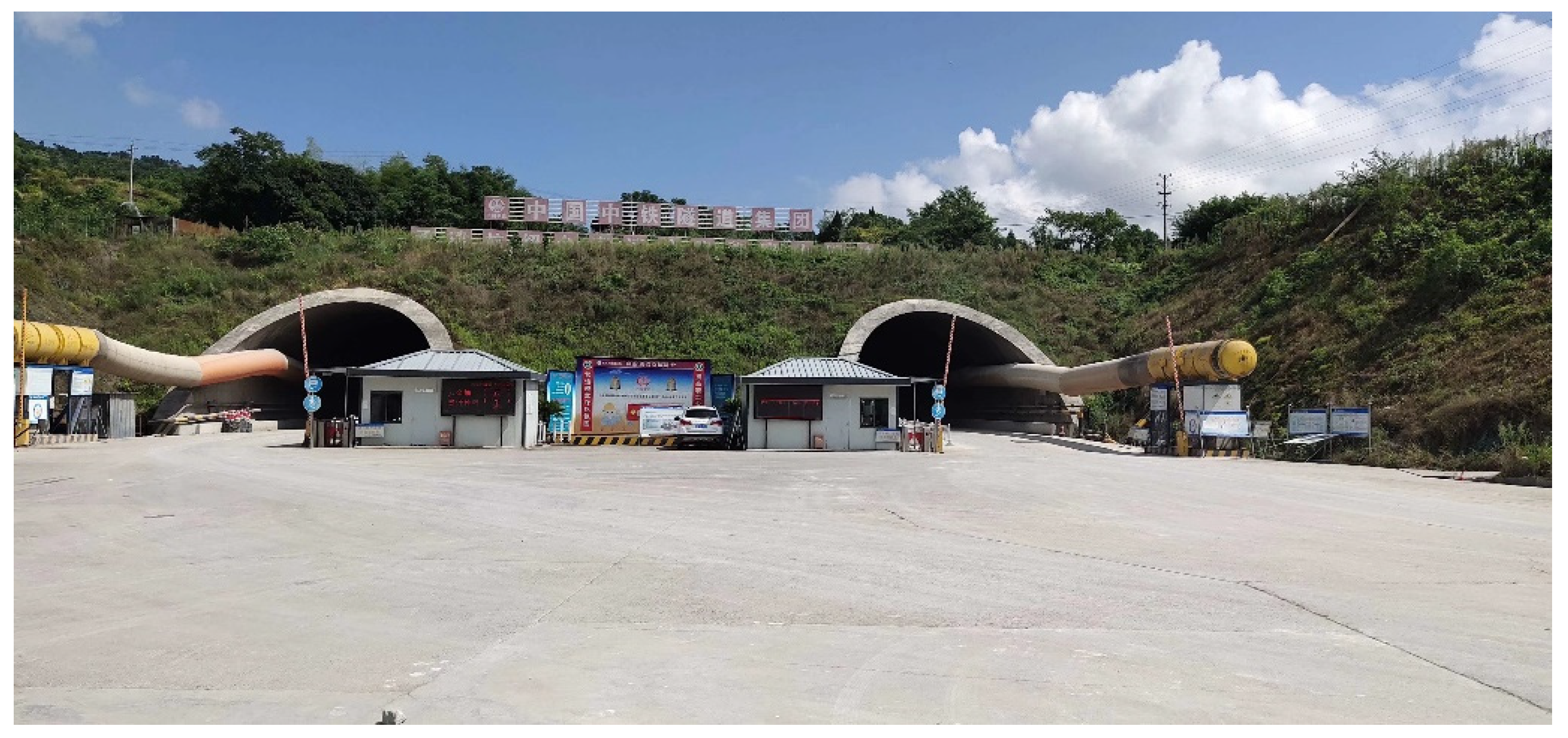
Chenjiashan tunnel is located in Xinchang County, Zhejiang Province, with a total length of 5947 m and a maximum buried depth about 250 m. It is a two-way, four lane expressway tunnel with separate upper and lower sections. The tunnel site is in an eroded and denuded low mountain and hilly area, with undulating mountains and narrow valleys. The route is basically laid along the river and gullies. The tunnel lithology changes greatly and is greatly influenced by the structure. The rock alteration is strong, joints and fissures has been developed, the groundwater is abundant, the hydrogeological conditions are complex, and the integrity is poor. A panorama photograph of the tunnel exit section is shown in Figure 1.
3. Mechanism Analysis of Tunnel Collapse
3.1. Description of Collapse Process
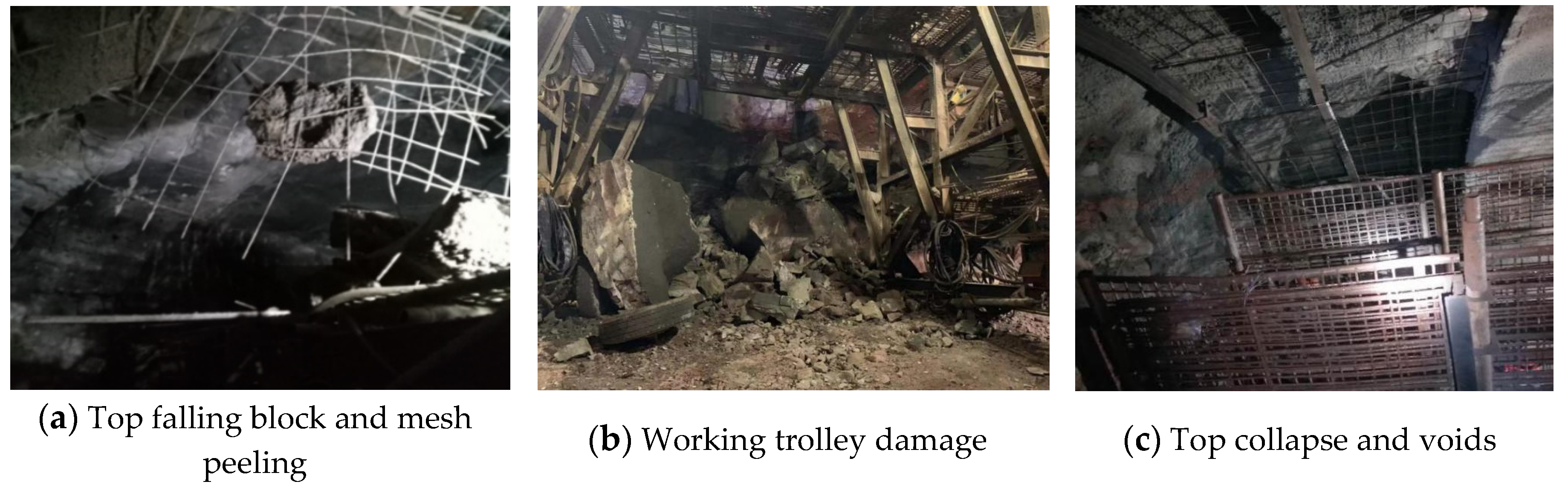
On the morning of 7 May 2018, the left tunnel face was excavated to ZK93 + 467. The surrounding rock fell off at the top of ZK93 + 470 near the face, causing great damage to the steel mesh and the working platform. The on-site staff and construction machinery were immediately evacuated. Soon afterwards, there was a sound of falling rocks, and a small-scale local collapse accident occurred on the vault and left side of the face, causing serious damage to the left side of the working trolley. The longitudinal length of the collapse area was about 2–3 m, the circumferential span was about 3 m, and the collapse height was about 1.5–2 m. The collapse photos of the tunnel site are shown in Figure 2.
3.2. Collapse Characteristics and Types
According to field conditions and a geological survey of the collapse area: (1) the collapsed rock mass was in a fragmentary structure, hard, unbreakable, with clear knocking sound, rough texture, and large amount of gray tuffaceous sandstone; (2) the exposed rock mass was in a gravel structure, with a partial fragmentary structure, an inclined structural fracture zone with a fragmentary mosaic structure developed in the middle and left, and extending to the left vault; (3) the structural surface of the collapse rock stratum was wet and smooth, with argillaceous sand body and local argillation; (4) the original design of the construction section was set as Class III surrounding rock, which adopted full section blasting construction, the initial support adopted hanging net and initial shotcreting; and (5) the lithology of the surrounding rock revealed in the geological exploration report was moderately weathered breccia bearing tuffaceous sandstone, tuffaceous sandstone and tuff, with good rock integrity and an integrity coefficient of 0.47–0.81; the comprehensive value was 0.64, the rock was relatively hard, and the uniaxial saturated compressive strength of the rock was between 34.8–63.2 MPa.
According to the comprehensive analysis, the collapse was considered to be a local block collapse of the unstable surrounding rock at the top of the tunnel.
3.3. Analysis of Collapse Causes
- The regional structure is mainly the fault structure, and the surrounding rock is mainly breccia tuffaceous sandstone, tuff, and sedimentary tuff of the Guantou formation of the Lower Cretaceous system. The lithology changes greatly, with strong rock alteration and well-developed joint fissures; the rock mass is of a fragmentary mosaic structure. The stress release during the excavation of surrounding rock tends to cause extrusion and internal bulging deformation, and the pressure stress concentration causes tensile fracture damage.
- The site mainly consists of eroded and denuded low mountain and hilly landforms. The tunnel passes through the surface reservoir, and the groundwater is sensitive to the tunnel construction. Under the influence of groundwater erosion and softening, the shear strength of the rock mass is reduced, and the cohesion between rock layers is reduced, which may induce shear slip near the structural zone.
- The tunnel uses a full-section blasting method, which significantly disturbs and crushes the surrounding rock mass. When the tensile stress on the structural surface is greater than its shear strength, the unstable block will be destroyed and shear slip will occur along the weak structural surface, causing the exposed broken block to flake off.
- Due to the failure of timely support after tunnel excavation, the surrounding rock was exposed for a long time, which lead to fracture development and stress state changes in the plastic loosening zone of the surrounding rock. As a result, the surrounding rock lost its stability and fell off.
- The excavation condition of surrounding rock is inconsistent with the geological survey report. Geological prospecting data show that this section is identified as grade III surrounding rock by geology, and the initial spray and hanging net support design was adopted based on geological prospecting data. In fact, under the influence of structure, the surrounding rock is more broken, the joints are more developed, and the blasting disturbance has a greater impact, which is more likely to result in the instability of surrounding rock due to the insufficient support strength.
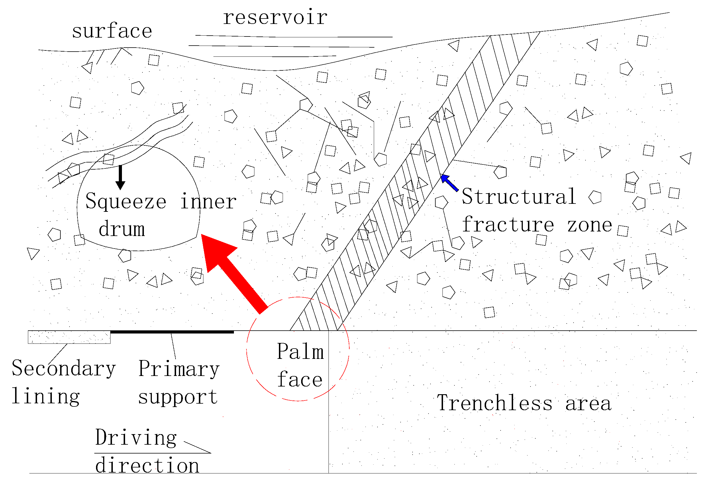
Based on the comprehensive analysis, the main factors causing the collapse of the tunnel were as follows: geological structure, groundwater influence, construction method, support measures and timing, survey and design problems. A generalized model of surrounding rock instability has been established (see Figure 3). It has revealed that the main cause of small-scale collapses is the combined action of the face extrusion and bulging deformation and the tension fracture of the inclined structure at the top stratum. In the process of balance arch formation at the arch roof, the support strength is not enough, and the stress release causes compression failure and collapse of the crushed block. The collapse can be classified as a local small-scale instability of the surrounding rock caused by the massive rock mass compression and shear failure along the structural plane.
3.4. Mechanism Analysis of Tunnel Collapse
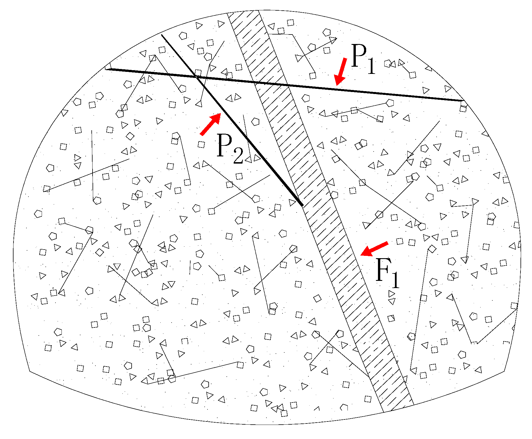
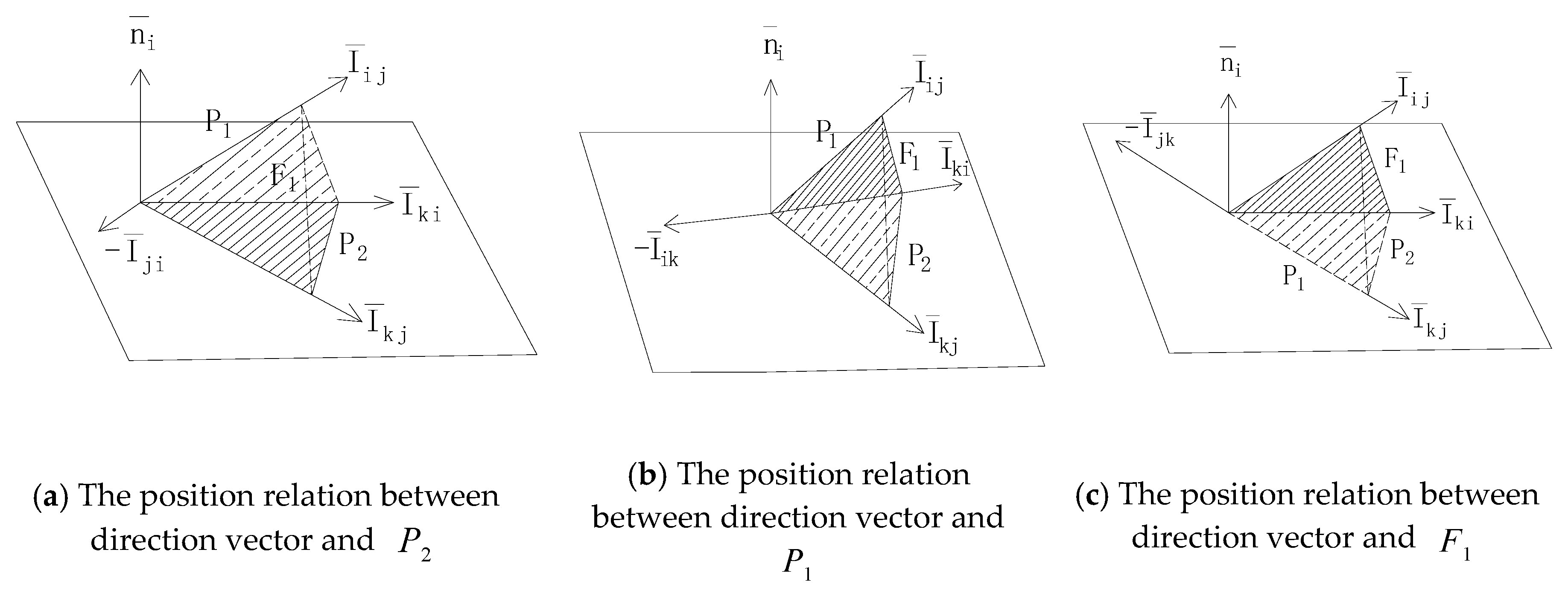
In a tunnel collapse, the collapse of the vault is mainly affected by the structure, and the unstable block is compressed and sheared along the structural plane. Therefore, based on block theory, this paper identifies the key blocks of the tunnel vault, analyzes their mobility, and reveals the collapse mechanism. On-site geological exploration revealed that the tunnel direction in the landslide area was SW5°–10°, intersecting with the tunnel axis at a small angle. There was a gentle fault F1 in the middle part of the tunnel face, and two groups of intersecting structural planes, namely P1 and P2, were exposed at the vault and left arch waist. The structural planes P1 and P2 cut each other, which was likely to cause wedge sliding failure. The structural plane of the tunnel excavation face is shown in Figure 4. The characteristics of the structural planesares shown in Table 1.
3.4.1. Analysis of the Mobility of Crack Cone in Structural Plane
- Calculation of the unit normal vector of each structural surface
The occurrence of a structural plane includes the dip angle and inclination . Based on the principle of stereographic projection, the structural plane can be expressed by equation in rectangular coordinate system:
Then, the normal vector of the structural plane is:
So there are:
- Calculation of the edge vector of each structural plane
By calculating the intersection line of each structural surface, that is, the edge vector, the spatial position relationship between the pyramid and each structural surface is determined. The edge vector is:
According to the calculation formula of the total number of edges:
When the number of structural faces , the total number of edge vectors is , the edge vectors are calculated as follows:
- Calculation of the direction parameter matrix of each structural plane
In view of all possible intersection combinations of the structural plane, the real edges of the pyramid are calculated. Introduction of direction parameters is described by the Equation:
The direction parameter is defined as the dot product of an edge vector and an upward unit normal vector of a plane, the point product of the edge vector and normal vector is used to judge the position relationship between edge and each structural plane:
, and are the unit normal vectors of , and which are the three structural surfaces as shown in Figure 5 According to the right-hand spiral rule the edge vectors are:
where , range from 1–3.
So there are:
where the angle between and is acute, is in the upper half space of structural plane , is shown in Figure 5a. Homology is,
where the angle between and is obtuse, is in the lower half space of structural plane , is shown in Figure 5b.
where the angle between and is acute, is in the upper half space of structural plane , is shown in Figure 5c.
According to the unit normal vector and edge vector of each structural plane, the direction parameter matrix is obtained as follows:
- Determination of the discrimination matrix corresponding to the blocke
According to the coincidence number diagonal matrix of block , the discriminant matrix of the block is:
A finite judgment is performed on each row of the matrix. If all elements in a row in are 0 or contain 1 and −1 at the same time, then the edge is unreal, if there are 0 and 1 or 0 and −1, then the edge is real; if all edges are unreal, then the corresponding block is a finite block, if only one of them is real, then it is an infinite block. Taking the No.101 block as an example, the discrimination matrix is:
So there are:
From the discriminant matrix and block finiteness discriminant method, we can know , , are defined as the true edge, fracture cone is non empty set, so the block is an infinite block. Similarly, the discriminant matrix of other blocks is calculated, and the specific results from our case study are shown in Table 2.
3.4.2. Analysis of the Mobility of Block Cone on Free Face
In the calculation of the block cone, the free face should be added into the calculation. In this paper, the tunnel vault is the free face, and the tunnel contour is considered to be a circular arch. The unit normal vector of the top surface is:
The edge vector of the intersection between the free surface and other structural surfaces is:
The direction parameter matrix is:
Similarly, No. 101 block is used as an example:
So there are:
According to the discriminant matrix and block finite discriminant method, the block cone is a non-empty set, so the block is an immovable block.
Accordingly, the same calculation is carried out for other blocks, and the results are shown in Table 2.
It can be seen that at the vault of the tunnel, No. 111 block is movable, and may collapse in the construction process. The rest blocks are immovable. Therefore, it is further indicated that the collapse of the vault is caused by the unstable partial and small-scale collapse of the key block.
4. Collapse Treatment Plan
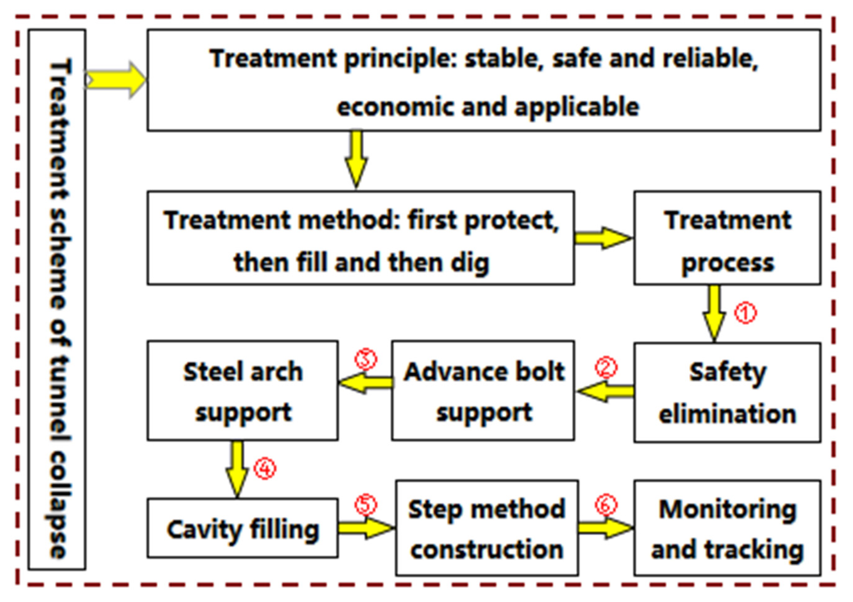
According to the collapse mechanism and characteristics, the treatment method of “first protect, then fill and then dig” is adopted, following the principle of “stable, safe and reliable, economical and applicable”. The specific treatment process is shown in Figure 6.
- Safe evacuation
After the tunnel collapsed, all construction was halted, and concrete was sprayed to cover the collapse surface. Dangerous rocks were removed in a timely manner to prevent secondary collapse.
- Advance bolt support
According to the scale and characteristics of the collapse, a Φ25 hollow grouting anchor bolt was installed immediately for advance support after the formation of a safe working face. The length of the anchor bolt was 3 m, and the spacing between the anchor bolts was 1.0 m. According to the plum staggered layout, more bolts were installed around the collapse chamber.
- Steel arch support
The initial support was strengthened, and the original surrounding rock support design of grade III was changed to that of grade IV (see Table 3). No.16 I-shaped steel was adopted, with a spacing of 0.8 m. Upon completion of the erection of the arch frame, longitudinal connecting steel bars and anchor bolts shall be installed immediately to fix the arch frame.
- Cavity filling
The surface of the collapsed body shall be closed by hanging steel mesh and shotcrete, and I16 steel arch frame shall be installed after curing. Steel plate bolts shall be used for circumferential connection and Φ25 steel bars shall be used for longitudinal connection. After the installation, the system anchor bolt and locking anchor bolt shall be drilled immediately and fixed with the steel arch frame. Φ25 hollow grouting anchor bolt was drilled obliquely around the collapse position to reinforce the loose collapse body in the tunnel section. When the strength of the collapsed body meets the requirements, concrete backfill shall be carried out to ensure that the arch back and surrounding rock would be bond together.
- Step method construction
According to the excavation principle of “weak blasting, short footage, early support”, blasting was strictly controlled, with each cycle footage about 1–2 m after excavation, concrete was sprayed to seal the surrounding rock in time to ensure the timely follow-up of support measures. The basic process was: blasting and excavation of upper stage→mechanical hazard check→installation of steel mesh→erection of steel arch frame→installation of system anchor bolt and locking anchor bolt→spraying concrete to complete the construction of upper stage. When the upper step is 5–10 m ahead of the lower step, the left and right sides of the lower step should be excavated alternately. Each excavation should be controlled at the spacing between 2–3 steel arches. Meanwhile, the foot locking anchor shall be strengthened to ensure the arch at the foot is stable.
- Monitoring and trackingn
The implementation should be carried out in strict accordance with the monitoring plan. The monitoring for special sections should be strengthened. The monitoring frequency should be improved, and the dynamic changes of surrounding rock should be closely monitored. Abnormalities should be reported immediately once they occur.
5. Evaluation of Treatment of Collapse
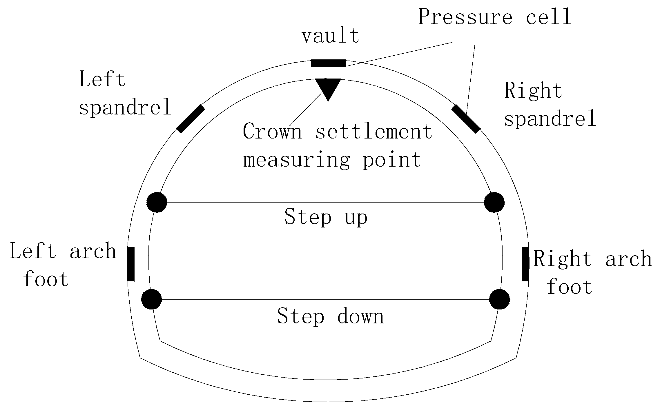
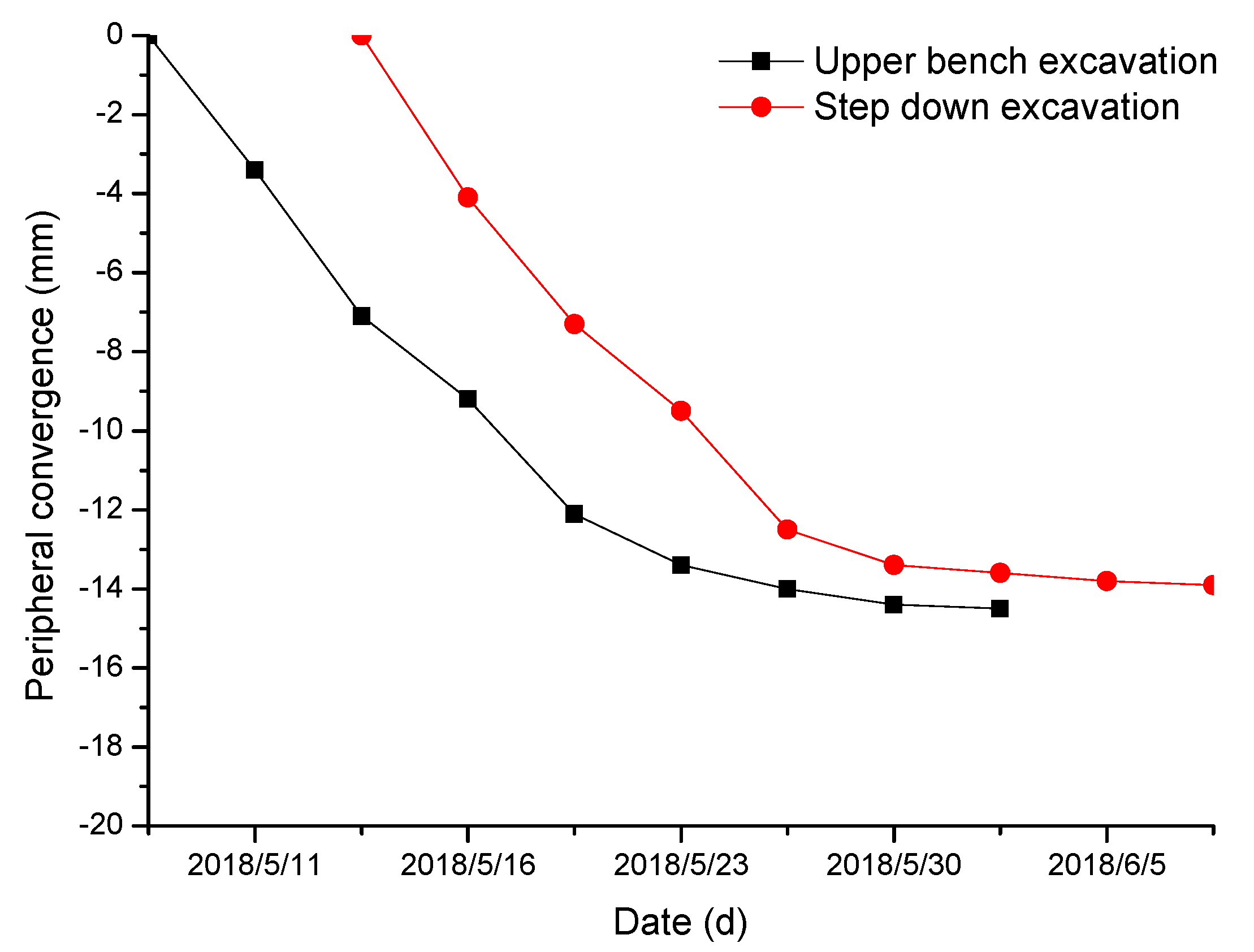
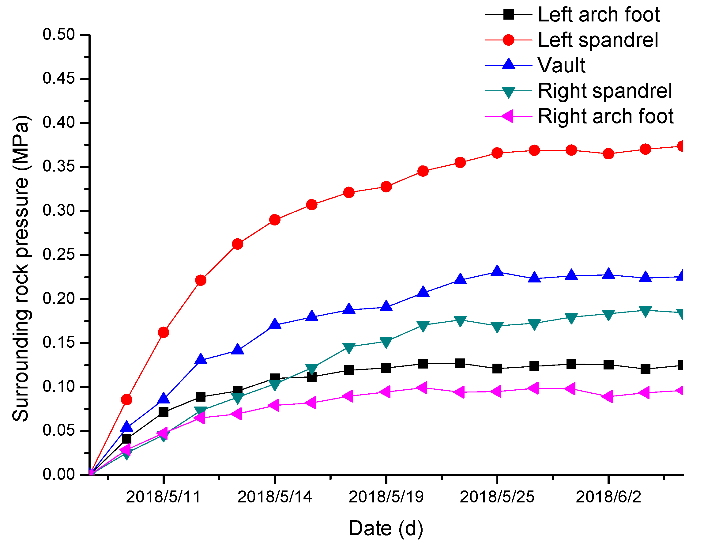
In order to evaluate the stability of the treatment effect of the collapse area, ZK93 + 465 monitoring section was set up on site to monitor the settlement of the vault, the surrounding convergence and the surrounding rock pressure. Among them, the tunnel was constructed by step method, one measuring point is arranged for vault settlement, and two measuring lines for upper and lower steps are arranged for horizontal convergence around the tunnel. By sticking reflectors on the measuring points, ZT30 total station was used for deformation measurement, with the measurement accuracy of 2 mm and 2 ppm. The surrounding rock pressure measuring points are arranged at the arch crown, the arch waist and the arch foot. In the construction process, the BK-1206S vibrating string double-mode pressure box is fixed on the contact surface of the steel arch frame with the force face upward. The maximum measuring range is 0.6 MPa and the measuring error is 0.001 MPa. The data is read by the intelligent pressure acquisition instrument. The layout of the measuring points is shown in Figure 7, and the monitoring results are shown in Figure 8, Figure 9 and Figure 10.
5.1. Monitoring Results of Surrounding Rock Deformation
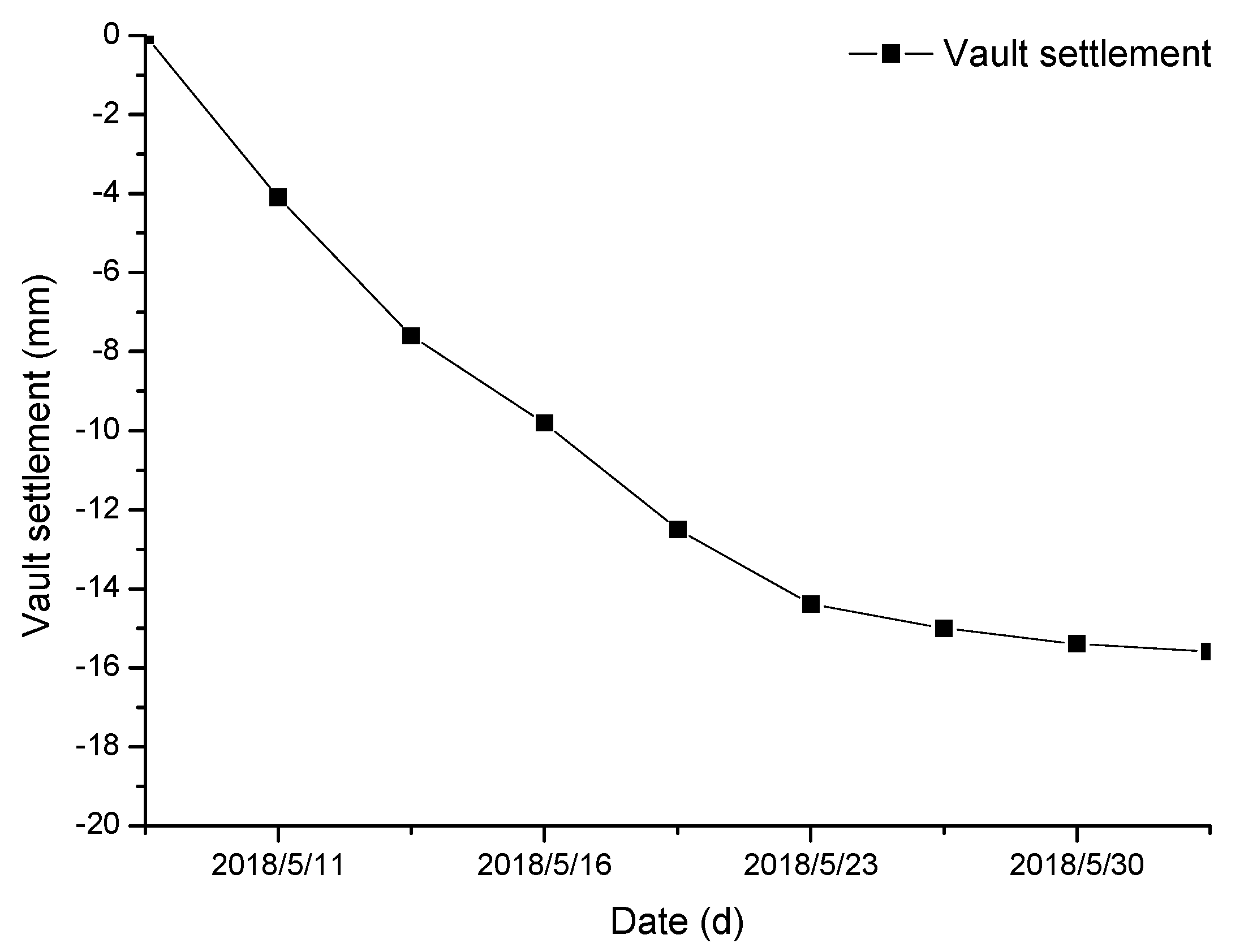
It can be seen that with the completion of treatment measures, the deformation of surrounding rock in the early stage increased rapidly; after about two weeks it began to grow slowly until it was basically stable. During the one-month period, the accumulated deformation of vault settlement and peripheral convergence were within 20 mm, and there was no obvious abnormal mutation or continuous growth trend, which is within the allowable deformation range. It shows that the measures to deal with the collapse of the tunnel are effective and the overall treatment effect is good, which ensures the safe and smooth construction.
5.2. Monitoring Results of Surrounding Rock Pressure
It can be seen that the pressure of surrounding rock developed rapidly in the early stage and reached the peak value in about one week. In the later stage, the change was small and gradually stabilized. Among them, the rock pressure of vault and left arch waist changed obviously, with the maximum value of 0.226 MPa and 0.374 MPa This indicates that after the collapse treatment, the supporting effect of the arch crown and left arch waist has been greatly strengthened during the process of stress release. It is believed that the surrounding rock in this part was relatively broken and with poor stability, which is basically consistent with the actual exposure. Under the action of support resistance, the stability value of surrounding rock pressure at each measuring point is in the controllable range, which indicates that the overall treatment effect of the collapse section is good.
6. Conclusions
(1) Based on the analysis of geological conditions, collapse characteristics and types, construction environment and other aspects, a generalized model of tunnel surrounding rock instability is established. The main reason of tunnel collapse is the combined action of the face extrusion and swelling deformation and the tension fracture of the inclined structure at the top stratum. Shear slip of massive rock along the structural plane is induced, resulting in the local small-scale collapse of the surrounding rock.
(2) Based on the block theory, the key blocks of the tunnel vault are predicted to be movable according to the occurrence of the structural plane. The results show that there is a movable block at the top of the tunnel, which further reveals the mechanism of the unstable collapse of the local block.
(3) According to the analysis of the reasons for the collapse of the tunnel, the main factors causing the collapse are: geological structure, groundwater impact, construction methods, support measures and construction timing, survey and design problems, etc., which are mutually affected and interrelated.
(4) Based on the mechanism and characteristics of tunnel collapse, following the principle of “stable, safe, reliable, economical and applicable”, the treatment method of “first protection, then filling and then excavation” was proposed. The comprehensive treatment measures of advance anchors, steel arch support, collapse backfill, and step excavation were adopted, and the construction monitoring was followed up to realize the escort.
(5) Based on field monitoring data, the deformation and stress characteristics of the surrounding rock in the collapse area has been analyzed. The treatment effect is good as a whole, which ensures the safety and smooth progress of the construction, achieves the expected goal, and accumulates successful experience for similar collapse cases of tunnel engineering.
Author Contributions
Conceptualization, S.Q. and Z.C.; Methodology, Z.C.; Software, Z.C.; Validation, Z.C., and J.T.; Formal Analysis, Z.C. and P.X.; Investigation, Z.C.; Resources, Z.C.; Data Curation, Z.C.; Writing—Original Draft Preparation, Z.C. and J.T.; Writing—Review and Editing, Z.C., J.T. and P.X.; Visualization, Z.C. and Y.Z.; Supervision, S.Q.; Project Administration, S.Q.; Funding Acquisition, S.Q. All authors have read and agreed to the published version of the manuscript.
Conflicts of Interest
The authors declare no conflict of interest.
References
- Li, R.; Han, N.N.; Yuan, C.F.; Chen, Q.R.; Yu, G.M.; Li, L.; Yuan, Z.J. Analysis and design optimization of collapse characteristics of Taojiakuang tunnel entrance section. Geotech. Geol. Eng. 2020, 38, 551–560. [Google Scholar] [CrossRef]
- Li, L.P.; Chen, D.Y.; Li, S.C.; Shi, S.S.; Zhang, M.G.; Liu, H.L. Numerical analysis and fluid-solid coupling model test of filling-type fracture water inrush and mud gush. Geomech. Eng. 2017, 13, 1011–1025. [Google Scholar]
- Zhang, Y.G.; Zhang, Z.; Xue, S.; Wang, R.J.; Xiao, M. Stability analysis of a typical landslide mass in the Three Gorges Reservoir under varying reservoir water levels. Environ. Earth Sci. 2020, 79, 2–14. [Google Scholar] [CrossRef]
- Shin, J.H.; Lee, I.K.; Lee, Y.H.; Shin, H.S. Lessons from serial tunnel collapse during construction of the Seoul subway Line 5. Tunn. Undergr. Space Technol. 2006, 21, 296–297. [Google Scholar] [CrossRef]
- Yang, X.L.; Huang, F. Collapse mechanism of shallow tunnel based on nonlinear Hoek–Brown failure criterion. Tunn. Undergr. Space Technol. 2011, 26, 686–691. [Google Scholar] [CrossRef]
- Yang, X.L.; Yan, R.M. Collapse mechanism for deep tunnel subjected to seepage force in layered soils. Geomech. Eng. 2015, 8, 741–756. [Google Scholar] [CrossRef]
- Yang, X.L.; Xu, J.S.; Li, Y.X.; Yan, R.M. Collapse mechanism of tunnel roof considering joined influences of non-linearity and non-associated flow rule. Geomech. Eng. 2016, 10, 21–35. [Google Scholar] [CrossRef]
- Osman, A.S.; Mair, R.J.; Bolton, M.D. On the kinematics of 2D tunnel collapse in undrained clay. Geotechnique 2006, 56, 585–595. [Google Scholar] [CrossRef] [Green Version]
- Wang, J.L.; Chen, J.P.; Su, S.R.; Yang, J. Discrete element study on collapse mechanism of jointed rock tunnel. J. China Univ. Min. Technol. 2008, 3, 316–319. [Google Scholar]
- Mete, K.; Turgay, O. Influence of the fault zone in shallow tunneling: A case study of Izmir Metro Tunnel. Tunn. Undergr. Space Technol. 2013, 33, 34–45. [Google Scholar]
- Zhou, Z.Q.; Li, S.C.; Li, L.P.; Sui, B.; Shi, S.S.; Zhang, Q.Q. Genesis and risk control of shallow tunnel collapse. Geotech. Mech. 2013, 34, 1375–1382. [Google Scholar]
- Zheng, G.; Cui, T.; Cheng, X.S.; Diao, Y.; Zhang, T.Q.; Sun, J.B.; Ge, L.B. Study of the collapse mechanism of shield tunnels due to the failure of segments in sandy ground. Eng. Fail. Anal. 2017, 79, 464–490. [Google Scholar] [CrossRef]
- Huang, F.; Zhao, L.H.; Ling, T.H.; Yang, X.L. Rock mass collapse mechanism of concealed karst cave beneath deep tunnel. Int. J. Rock Mech. Min. Sci. 2017, 91, 133–138. [Google Scholar] [CrossRef]
- Fraldi, M.; Guarracino, F. Analytical solutions for collapse mechanisms in tunnels with arbitrary cross sections. Int. J. Solids Struct. 2010, 47, 216–223. [Google Scholar] [CrossRef]
- Fraldi, M.; Guarracino, F. Evaluation of impending collapse in circular tunnels by analytical and numerical approaches. Tunn. Undergr. Space Technol. 2011, 26, 507–516. [Google Scholar] [CrossRef]
- Salvador, S.; Rafael, J. A tunnel face failure mechanism for layered ground, considering the possibility of partial collapse. Tunn. Undergr. Space Technol. 2015, 47, 182–192. [Google Scholar]
- Wang, C.B. Study on Progressive Failure Mechanism of Surrounding Rock of Soft and Broken Tunnel. Ph.D. Thesis, Tongji University, Shanghai, China, 2007. [Google Scholar]
- Zhang, N.; Jack, S.L.S.; Cheng, L.; Arul, A.; Chai, J.C. Investigation of a large ground collapse and countermeasures during mountain tunneling in Hangzhou: A case study. Bull. Eng. Geol. Environ. 2019, 78, 991–1003. [Google Scholar] [CrossRef]
- Li, L.P.; Wang, Q.H.; Li, S.C.; Huang, H.W.; Shi, S.S.; Wang, K.; Lei, T.; Chen, D.Y. Cause analysis of Soft and hard rock tunnel collapse and information management. Pol. J. Environ. Stud. 2014, 23, 1227–1233. [Google Scholar]
- Tseng, D.J.; Tsai, B.R.; Chang, L.C. A case study on ground treatment for a rock tunnel with high groundwater ingression in Taiwan. Tunn. Undergr. Space Technol. 2001, 16, 175–183. [Google Scholar] [CrossRef]
- Turkmen, S.; Ozguzel, N. Grouting a tunnel cave-in from the surface: A case study on Kurtkulagi irrigation tunnel, Turkey. Tunn. Undergr. Space Technol. 2003, 18, 365–375. [Google Scholar] [CrossRef]
- Kim, J.K.; Hemphill, G.B.; Stewart, W.; Tinkler, J. Methods of re-mining tunnel T08 at THSRC contact C230 after a collapse. Tunn. Undergr. Space Technol. 2006, 21, 320. [Google Scholar] [CrossRef]
- Benton, L.; Grose, W.J. Hull waste-water flow transfer tunnel: Tunnel collapse and causation investigation. Geotech. Eng. 2005, 158, 179–185. [Google Scholar]
- Chen, Q.N.; Zhang, Y.X.; Liu, X.R.; Wang, S.G.; Zhou, Y.L.; Qiu, X.H. Construction monitoring and simulation analysis after reinforcement of tunnel collapse area. J. Rock Mech. Eng. 2006, 1, 158–161. [Google Scholar]
- Chen, Q.N.; Zhao, M.H.; Zhou, G.H.; Huang, S.P.; Zhou, Y.L. Cause analysis of tunnel collapse in complex layered strata and information construction technology after reinforcement. Geotech. Mech. 2009, 30, 650–653. [Google Scholar]
- Wu, Q. Study on the Mechanism and Treatment Measures of Collapse Disaster in Mayakou Tunnel. Master’s Thesis, Chongqing University, Chongqing, China, 2009. [Google Scholar]
- Liu, P.; Di, L.P.; Du, Q.; Wang, L.Z. Remote sensing big data: Theory, methods and applications. Remote Sens. 2018, 10, 711. [Google Scholar] [CrossRef] [Green Version]
- Mistretta, F.; Sanna, G.; Stochino, F.; Vacca, G. Structure from motion point clouds for structural monitoring. Remote Sens. 2019, 11, 1940. [Google Scholar] [CrossRef] [Green Version]
- Ding, Z.; Liao, X.H.; Su, F.Z.; Fu, D.J. Mining coastal land use sequential pattern and its land use associations based on association rule mining. Remote Sens. 2017, 9, 116. [Google Scholar] [CrossRef] [Green Version]
- Wang, S.H.; Ni, P.P.; Guo, M.D. Spatial characterization of joint planes and stability analysis of tunnel blocks. Tunn. Undergr. Space Technol. 2013, 38, 357–367. [Google Scholar] [CrossRef]
- Zuo, Q.J.; Wu, L.; Lin, C.Y.; Xu, C.M.; Li, B.; Lu, Z.L.; Yuan, Q. Mechanism analysis and treatment measures for collapse of water rich soft rock tunnel across fault. J. Rock Mech. Eng. 2016, 35, 369–377. [Google Scholar]
- Wang, Y.L.; Tan, Z.S. Structural instability analysis and preventive measures for collapse of Muzhailing slate tunnel. Geotech. Mech. 2012, 33, 263–268. [Google Scholar]
- Zuo, Z.; Zhang, J.R.; Fu, H.L.; Peng, W.X. Collapse analysis of tunnel portal based on catastrophe theory. Elec. J. Geotech. Eng. 2019, 24, 237–244. [Google Scholar]
- Zhang, G.H.; Jiao, Y.Y.; Chen, L.B.; Wang, H.; Li, S.C. Analytical model for assessing collapse risk during mountain tunnel construction. Can. Geotech. J. 2016, 53, 326–342. [Google Scholar] [CrossRef]
- Prasad, V.V.R.; Dwivedi, R.D.; Swarup, A. Determination of support pressure for tunnels and caverns using block theory. Tunn. Undergr. Space Technol. 2013, 37, 55–61. [Google Scholar] [CrossRef]
- Zhang, Z.X.; Wang, S.F.; Huang, X. Analysis on the evolution of rock block behavior during TBM tunneling considering the TBM–block interaction. Rock Mech. Rock Eng. 2018, 51, 2237–2263. [Google Scholar] [CrossRef]
- Zhang, Z.X.; Wang, S.F.; Huang, X.; Rostami, J. Application of block theory for evaluating face stability under disc cutters loading of TBM, case study of a water-conveyance tunnel project. Tunn. Undergr. Space Technol. 2019, 90, 249–263. [Google Scholar] [CrossRef]
- Jiang, A.; Jin, L.F. Failure risk analysis of rich water area tunnel based on support vector machine and particle swarm optimization. Disaster Adv. 2013, 6, 487–497. [Google Scholar]
- Li, X.; Li, X.B.; Su, Y.H. A hybrid approach combining uniform design and support vector machine to probabilistic tunnel stability assessment. Struct. Saf. 2016, 61, 22–42. [Google Scholar] [CrossRef]
Figure 1.
Panoramic view of tunnel exit.

Figure 2.
Photos of tunnel collapse.

Figure 3.
General model of tunnel surrounding rock instability.

Figure 4.
Structural plane diagram of tunnel face.

Figure 5.
Geometric meaning of direction parameter.

Figure 6.
Flow chart of tunnel collapse treatment.

Figure 7.
Layout of measuring points of monitoring section.

Figure 8.
Settlement time history curve of arch crown.

Figure 9.
Time history curve of peripheral convergence.

Figure 10.
Time history curve of surrounding rock pressure.


Table 1.
Characteristics of the structural plane.
| Structural Plane | Inclination (°) | Dip Angle (°) | Remarks |
|---|---|---|---|
| F1 | 250 | 20 | Shelving fault |
| P1 | 185 | 75 | |
| P2 | 65 | 45 |
Table 2.
Calculation results of movable block of tunnel vault.
| Block Number | Crevice Cone | Block Cone | Movable or Not |
|---|---|---|---|
| 000 | Nonempty set | Nonempty set | No |
| 001 | Nonempty set | Nonempty set | No |
| 010 | Nonempty set | Nonempty set | No |
| 100 | Nonempty set | Nonempty set | No |
| 011 | Nonempty set | Nonempty set | No |
| 110 | Nonempty set | Nonempty set | No |
| 101 | Nonempty set | Nonempty set | No |
| 111 | Nonempty set | Empty set | Yes |
Table 3.
Initial support parameters of tunnel.
| Grade of Surrounding Rock | Bolt | Steel Mesh | Shotcrete | Steel Arch |
|---|---|---|---|---|
| IV | Φ25 bolt, spacing 1.0 × 1.0 m, Length 3 m | A6 | 20 cm C25 concrete | I16 steel arch, spacing 0.8 m |
| III | Φ25 bolt, spacing 1.5 × 1.5 m, Length 2.5 m | A6 | 10 cm C25 concrete | / |
© 2020 by the authors. Licensee MDPI, Basel, Switzerland. This article is an open access article distributed under the terms and conditions of the Creative Commons Attribution (CC BY) license (http://creativecommons.org/licenses/by/4.0/).
Share and Cite
MDPI and ACS Style
Qiao, S.; Cai, Z.; Tan, J.; Xu, P.; Zhang, Y. Analysis of Collapse Mechanism and Treatment Evaluation of a Deeply Buried Hard Rock Tunnel. Appl. Sci. 2020, 10, 4294. https://0-doi-org.brum.beds.ac.uk/10.3390/app10124294
AMA Style
Qiao S, Cai Z, Tan J, Xu P, Zhang Y. Analysis of Collapse Mechanism and Treatment Evaluation of a Deeply Buried Hard Rock Tunnel. Applied Sciences. 2020; 10(12):4294. https://0-doi-org.brum.beds.ac.uk/10.3390/app10124294
Chicago/Turabian StyleQiao, Shifan, Ziyong Cai, Junkun Tan, Ping Xu, and Yonggang Zhang. 2020. "Analysis of Collapse Mechanism and Treatment Evaluation of a Deeply Buried Hard Rock Tunnel" Applied Sciences 10, no. 12: 4294. https://0-doi-org.brum.beds.ac.uk/10.3390/app10124294
Note that from the first issue of 2016, this journal uses article numbers instead of page numbers. See further details here.