Qualitative Prediction Model for Dynamic Behavior of Ballasted Tracks

1
Department of Construction Engineering, Dongyang University, No. 145 Dongyangdae-ro, Punggi-eup, Yeongju-si, Gyeongsangbuk-do 36040, Korea
2
Department of Architectural Engineering, Gachon University, 1342 Seongnamdaero, Sujeong-gu, Seongnam-si, Gyeonggi-do 13120, Korea
*
Author to whom correspondence should be addressed.
Appl. Sci. 2020, 10(18), 6258; https://0-doi-org.brum.beds.ac.uk/10.3390/app10186258
Submission received: 13 August 2020
/
Revised: 5 September 2020
/
Accepted: 6 September 2020
/
Published: 9 September 2020
(This article belongs to the Special Issue Advances on Structural Engineering, Volume II)
Abstract
:Theoretical, experimental, analytical, and statistical evaluations were performed to predict and assess the dynamic behavior of a ballasted track, such as the track support stiffness, track impact factor, or dynamic wheel–rail forces. Field measurements were then performed to evaluate the dynamic behavior of the ballasted track and its components. A qualitative prediction model was then developed to predict and assess track performance as a function of dynamic wheel-rail force and variation in track support stiffness. The developed two-degree-of-freedom dynamic track model can define the rail pad and ballast stiffness ranges based on designed and measured values. Using the proposed model, qualitative analysis results are presented as a discrete space of various track responses and parameters, rather than as single values. The proposed model was then validated using field measurements, which demonstrated that the proposed model predicted the vertical rail displacement and rail bending stress within approximately 2–5% of the obtained field measurements. Overall, the developed qualitative prediction model allows the dynamic response of in-service ballasted tracks to be estimated as a function of the rail pad and ballast stiffness using only a simple field measurement.
1. Introduction
The environmental and mechanical conditions to which ballasted railway tracks are exposed to during service causes them to degrade and deteriorate. Because ballasted track structures subject to dynamic loading are usually constructed from various track components made with varying materials, their behavior cannot be easily verified or predicted. Moreover, the low reliability of input variables used in ballasted track analysis can have a potentially large effect on the solution.
The dynamic response of ballasted track is affected by several parameters, such as rail pad and ballast stiffness, rail surface roughness, and the condition of track components. Among these, the spring stiffness of the rail pad and ballast has been demonstrated to be most influential to the track support stiffness.
The track support stiffness (i.e., track stiffness) influences the bearing capacity of the track, the dynamic interaction force between a vehicle and the track, the quality of the track geometry, and the service life of track components. In general, relatively high track stiffness is beneficial as it provides sufficient track resistance to applied loads and results in decreased track deflection, which reduces track deterioration [1,2,3,4]. However, very high track stiffness leads to increased dynamic forces in the wheel-rail interface and on the sleepers and ballast, which may cause wearing and fatigue of track components [1,2,3,4,5,6,7,8]. The track stiffness is also known as a basic parameter that refers to the essential requirement “technical compatibility”. Hence, further efforts are required to develop a rational approach to the track design and construction to ensure that the track stiffness and its variations are within an acceptable range of values, or ideally, to achieve an optimum track stiffness [2,8,9,10,11,12]. Furthermore, the measurement methods for the track stiffness must provide accurate, precise, and reproducible results to evaluate the performance of existing tracks and thus to make appropriate decisions regarding track maintenance. A variety of researchers, including Fröhling, and Wu and Thompson conducted research in this area, and this has been reviewed and summarized by Hunt [10,11,12,13,14,15,16,17,18,19,20,21,22,23].
Ngamkhanong et al. presented a review of sensors used for the structural monitoring of railway track infrastructure, as well as their application to sense the performance of different track components during extreme events [24]. Ngamkhanong et al. presented the dynamic response between vehicle and track considering degradations of rail pads [25]. Lim et al. suggested a rational analysis method for a track ballast wheel interaction that could be further developed to model the interaction in a train-derailment event, based on the discrete-element method (DEM) [26]. Tsunashima analyzed the effects of railway track irregularities on car-body vibrations through railway vehicle travel simulations conducted using the SIMPACK software package [27]. Some researchers analyzed the dynamic behavior of railway through experiments and finite element analysis [28,29,30,31]. In addition, through monitoring of the railway, the condition of safety serviceability was confirmed with the maintenance of the railway due to aging factors [32,33].
This work, therefore, aims to develop a predictive model relating quantitative and qualitative parameters of a ballasted track to allow for better track design. To do so, theoretical, experimental, analytical, and statistical evaluations were performed to predict and assess a variety of dynamic ballasted track characteristics, including the track support stiffness, track impact factor, dynamic wheel−rail forces, track displacement, and subgrade modulus. In addition, field measurements for evaluating the dynamic characteristics of a ballasted track and its components were performed. The qualitative prediction model (QPM) comprises a two-degrees-of-freedom (2DOF) dynamic track model and modified track properties, which define the rail pad and ballast stiffness ranges, based on designed and measured values. The QPM for dynamic track behavior was developed in this study, which was capable of simulating the complex interaction between the properties of track components and track responses. The qualitative analysis was defined by the prediction method of the track response using the analytical matrices functions, which was validated by field measurement, i.e., related to the empirical theory for dynamic track mechanics, and the results of qualitative analysis showed as the discrete surface area (herein referred to as space solution). The analysis for the dynamic track response of the ballasted track was needed to vary the parameter of track components and track force related to the behaviors of ballasted track. Therefore, the numerical model was performed by conventional theory of track dynamics, and then, it was compared with the measured results in the real field. The results of the track response that was investigated by qualitative analysis were validated by the measured results.
The qualitative prediction model (QPM) was then designed and validated using field measurements. The proposed QPM model can thus be used to assist in the design and maintenance of ballasted track components, especially regarding the rail pad and ballast.
2. Qualitative Analysis
2.1. Qualitative Analysis for Track Engineering
A track design and maintenance problem may be broken down into a set of functional responses, such as the structural life at the according conditions of track components [1,2,3,4,8,12,34,35]. These static and dynamic responses can be easily represented in terms of inequalities [1,2,3,7]. Since the relevant geometric and engineering principles are applied within the scope of such functional responses, most important engineering decision-making involves judgments regarding inequalities. However, inequality constraints define solutions in the form of solution spaces; single-point solutions are sought in engineering due to the fact that complete solution spaces are too difficult to compute. Qualitative reasoning allows the complete solution space to be derived from a set of constraints [8,12,34,35].
The principal technique employed in qualitative reasoning is constraint satisfaction [8,34,36,37]. Engineering tasks are well suited to the formulation as constraint satisfaction problems (CSPs), which are defined by a set of variables subject to constraints. The variables correspond to the relevant parameters of the design formulas, whereas the constraints express design criteria by equalities or inequalities [8,35,38].
Using CSP in this field is beneficial, as consistency techniques represent an approximation of both input variables and solution spaces instead of single-point values [8,35,38].
A low reliability of the input variables and parameters used in ballasted track analysis can have a potentially large effect on the solution due to the complex relationships between the equations [8]. A qualitative description of track response can use multiple colors and discrete space areas, rather than single values, to represent several uncertain variables. The proposed QPM thus consists of a two-degree-of-freedom (2DOF) dynamic track model and modified track properties, which define the rail pad and ballast stiffness ranges based on designed and measured values. A basic qualitative analysis was used to estimate and predict the track parameters and dynamic track response of a field, which is presented as a qualitative analysis map. The proposed QPM determines the various track responses as ranges of variable properties and parameters using data acquired from field measurements.
2.2. Application of Qualitative Analysis to Track Dynamics
Track dynamics theory (i.e., beam on continuous elastic foundation as defined by Zimmermann) and qualitative analysis were then applied to simulate track dynamics. The qualitative analysis mainly focuses on track dynamics theory describing the track stiffness, i.e., related to the rail pads, ballast and subgrade stiffness, and track impact factor, whose response depends on the track stress, displacement, and resonance in the vertical plane.
The model is then used to calculate the beam bending stiffness EI (N∙m2) and the foundation stiffness (i.e., the ballast bed modulus) k (N/m2, i.e., N/m per unit meter rail) [1,2]. The rail deflection w(x) (where x is the length coordinate) was then obtained from the following differential Equation (1):
where q(x) is the distributed load on the rail (N/m).
The discrete rail support model, a continuous model, reproduces the pinned−pinned frequency on distributed layers [1,2,39]. In their investigation of track support behavior, Grassie and Cox [39] concluded that poorly damped sleeper resonances lead to higher sleeper stress [1,2,40].
The rails, sleepers, and rail pads (and ballasts) were modeled as a beam (via Euler-Bernoulli or Rayleigh-Timoshenko beam theory), a rigid mass, and a spring damper, respectively [1,2,41].
Track support stiffness k (kN/mm) (i.e., the precise dynamic track stiffness) can be defined as the ratio between the vertical force Q (kN) on the rail and the vertical track displacement w (mm) as [9]:
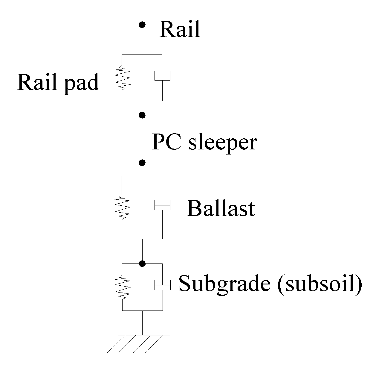
Therefore, the dynamic track stiffness is dependent on the applied load, or a function of the excitation frequency f in the time t domain. Conventional track calculations were based on a static approach developed by Zimmermann [9]. The ballasted track model, as represented by Sato et al. [4], is shown in Figure 1, where a spring damper element represents a track component [4], the sleeper spacing is represented by a, and the total of series support stiffness of the rail pad, ballast, and subgrade is ks.
The governing set of differential equations accounting for these boundary conditions defines the rail displacement w (mm), sectional moment of the rail M (cm4), and pressure load on sleeper F (kN) as [9]:
where L is the characteristic length of the track (mm), as [3,9]:
and ks is determined from the pad stiffness kpad and ballast/subgrade stiffness kbs (kN/mm), as [3,9]:
Using Equation (2), the static track stiffness can thus be calculated as [3,9]:
Thus, the track support stiffness is a function of the structural properties of the rail, rail pad, sleeper, and ballast and subgrade.
Recently, track models presented for dynamic vehicle–track interaction have been used to investigate the dynamic track stiffness, in which a finite element (FE) model is conducted by the half of track model, the rail is modeled by Rayleigh-Timoshenko beam theory, and the sleepers are considered as rigid masses [9,10]. Here, the FE model of ballasted tracks consisted of one rail of finite length, discretely supported via rail pads by sleepers on the ballast/subgrade [1,2,42]. The rail pad and ballast/subgrade were also modeled as a series of elastic springs and viscous dampers [9,10]. The structural dynamic equations are represented as:
where M, C, and K are the mass, damping, and stiffness matrices of the track, respectively, and F is the applied load vector [9]. In the frequency domain, this can be represented as [9]:
Assuming that F is a unit load vector acting at an excitation position on the rail, the track receptance is the solution of U at the loading position; the dynamic track stiffness was then calculated as the inverse of the track receptance [9]. The rail is defined by Young’s modulus E (kN/cm2), shear modulus G (kN/cm2), density ρ (kN/cm3), cross-sectional area A (cm2), second moment of area of section I (cm4), and shear coefficient κ; the bending stiffness is represented by B = EI and the shear stiffness by K = GAκ [10]. The sleeper was calculated by mass ms, whereas the rail pad and the ballast were modeled by their respective stiffness and loss factor kpad and ηpad, and kbal and ηbal, respectively [10]:
The wheel and point forces are assumed to be exerted on each support of the rail. The dynamic stiffness (impedance) S(ω) is related to the force at each support point and corresponding displacement ûn as [10]:
The dynamic response of the in-service ballasted track was relatively random or higher than the results of FE analysis, and was, therefore, distributed more roughly and over a wider range than its initial design value (i.e., the value considered during track construction) [1,2,3,18,22,43]. Therefore, the dynamic response of in-service ballasted tracks does not depend on a single track structure parameter. The constitutive track model was then applied to define the continuous equivalent stiffness properties in the longitudinal direction based on an anisotropic formulation, since the sleepers are usually held in contact with the ballast by a linking element. The connection between the rail and the sleepers was assumed to be a single vector response on the rail and to only correspond to the vertical displacement; thus, the motion of the rail in the transformed domain is expressed as [1,2,9,44]:
where EIk1 is the bending stiffness of the rail (kN/cm2), kp is the complex stiffness of the rail pad (kN), mr is the rail’s mass per unit length (kN/cm), and the vectors u and f represent the displacement and load on the rail (m), respectively [35]. The superscript * in kp represents the complex stiffness), which accounts for the damping properties of the rail pad; , where cp represents the viscous damping factor. The stiffness and mass matrices of the rail were then assembled to the dynamic system functions [1,2,41,44,45].
The qualitative analysis was defined by the display method of the analytical matrices over a discrete surface area (space solution) [46,47,48]. As analyzing the dynamic response of the ballasted track requires the relationship between the track component and force parameters and the track behavior, a numerical model based on conventional track dynamics theory was compared with the FE analysis and the field measurements. These track response, as detailed by the qualitative analysis, was then validated using the field measurements. The dynamic behavior of the ballasted track was qualitatively estimated and predicted by a numerical model, i.e., the ballasted track including the spring-damper element (2DOF), which considered the range of spring stiffness according to the actual and design parameters. Furthermore, the qualitative analysis of the dynamic response of track matrices—represented by the shared solution space of the three empirical equations according to Winkler beam theory and Zimmermann theory—at different ranges of rail pad and ballast stiffness was a function of the discrete space area of response for tracks. The properties of the rails and sleepers and the parameters of the target track used in the qualitative analysis are listed in Table 1 and Table 2, respectively.
3. Field Measurements
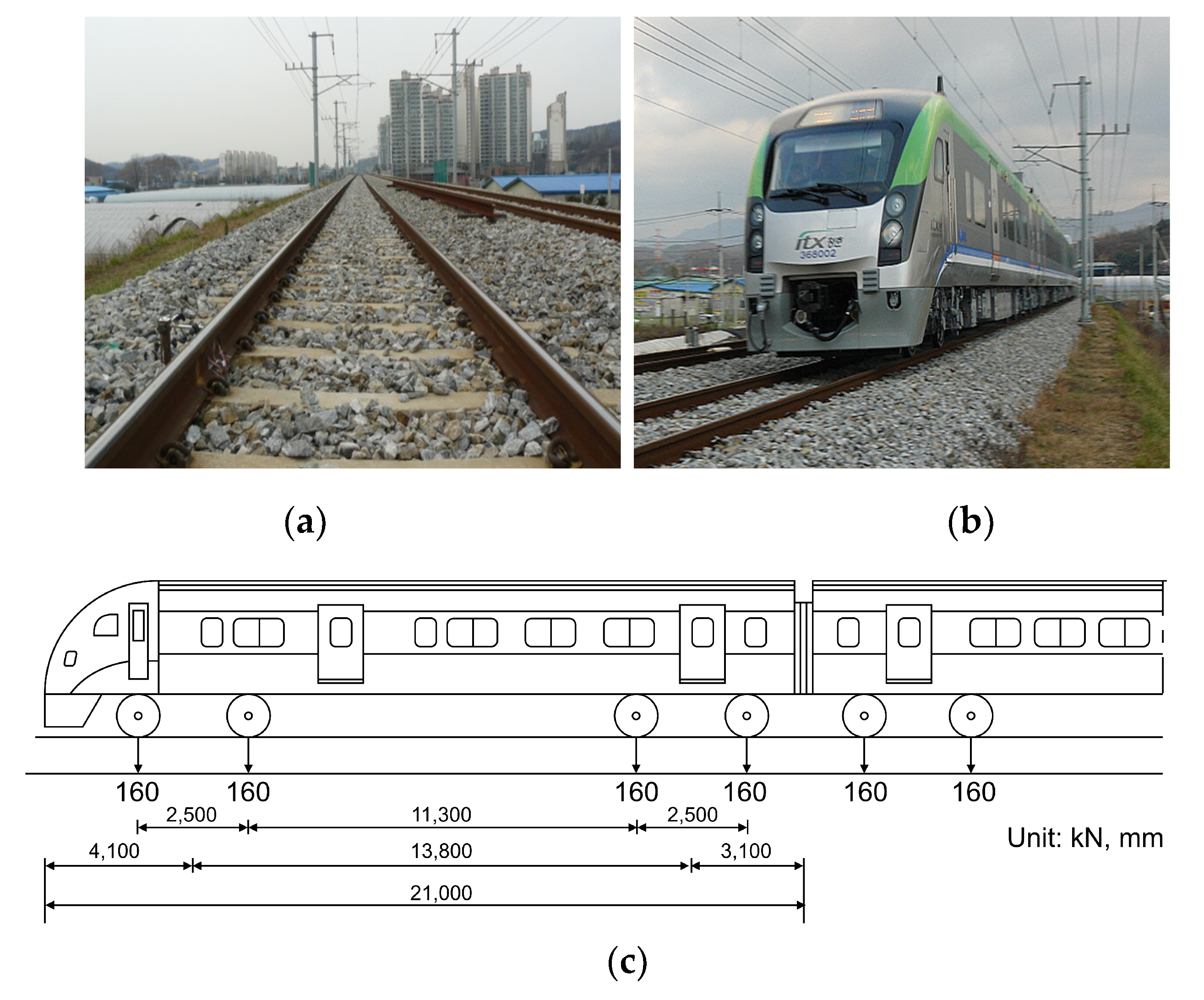
Field measurements of the dynamic response of a test track were then conducted, including the dynamic wheel load, rail and sleeper displacement, and rail bending stress. The studied ballasted railway line was an in-service straight and continuous welded rail (CWR) track weighing 60 kg located in the Republic of Korea. The design subgrade modulus was estimated according to the Korean standard KS F2310 for subgrade materials, which was adopted at the time of the construction [49,50,51]. Parameters and photographs of the test site are shown in Table 2 and Figure 2a,b, respectively, and the vehicle load composition during testing is shown in Figure 2c.
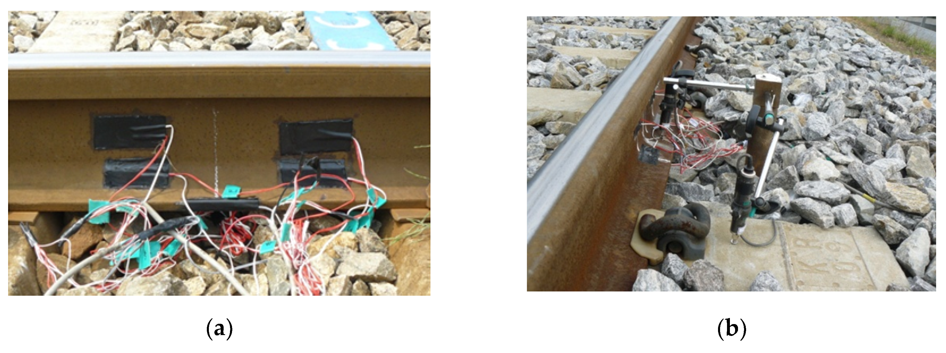
The dynamic wheel load acting on the track segment subjected to the load of a passing train was measured by installing a two-axis strain gauge on the rail web between the two test sleepers [13]. The measured signal was recorded on a data acquisition system (MGC-Plus) and analyzed using the Origin™ program. To eliminate interference from other passing trains and obtain a reliable measure of the dynamic wheel load of the passing train, measurements were performed using a wheel load gauge wired to eight strain gauges at an angle of 45° and attached along the neutral axis of the rail web 100 mm from the center of the sleepers, as shown in Figure 3a.
The vertical wheel loads were measured using shear strain gauges coupled to a full Wheatstone bridge circuit [52]. The strain gauge bridges were calibrated using a hydraulic ram and load cell to obtain measurements with an accuracy of 2% [13,52]. To prevent data distortion and loss, the sampling rate was > 1 kHz.
In Figure 3a, the strain gauge installed on the web of the rail is a sensor for measuring the wheel load. LVDT was used as a sensor to measure the displacement of rail and sleepers as shown in Figure 3b. The rail bending strain on the test track was measured using a one-axis strain gauge attached longitudinally to the bottom flange of the rail at the center of the sleepers, as shown in Figure 3a [13]. The dynamic displacement of two consecutive sleepers was measured relative to a reference frame anchored 2.0 m below the top of the sleepers, as shown in Figure 3b [13]. The beam was assembled to measure the absolute vertical displacement of the two sleepers on each side of the instrumented track as the train passed over it. Vertical rail displacements were measured using displacement transducers, such as linear variable differential transformers (LVDTs), mounted on a jig anchored under the ballast layer of the track, as shown in Figure 3b.
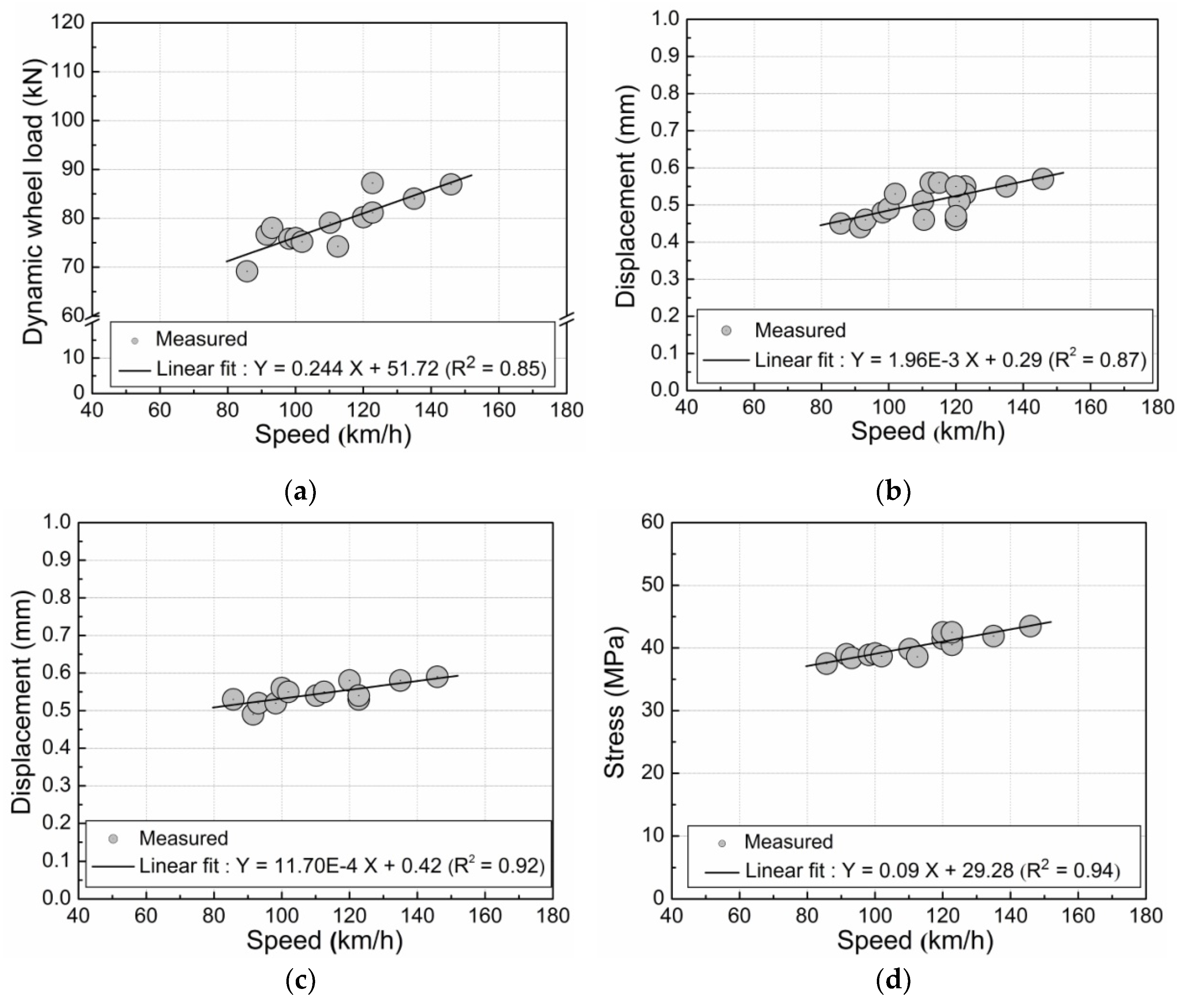
The resulting variations in the dynamic response of the ballasted test track are shown in Figure 4. The dynamic wheel load and rail displacement increased with increasing train speed, as shown in Figure 4a,b; the sleeper displacement and rail bending stress slightly increased with increasing train speed, as shown in Figure 4c,d.
4. Results and Discussion
4.1. Assessment of the Track Parameters Using the Proposed Qualitative Analysis
The effect of the (vertical) track support stiffness and the influence of variations to the rail pad and ballast stiffness on the track support stiffness and associated track responses were then investigated. Some of the values used in the numerical simulations were obtained from previous numerical and experimental studies [1,2,9,17,18,19,20,21,22,23,41,45,49]. Overall, the track response was affected by several parameters, including the rail pad and ballast stiffness, rail surface roughness, and condition of track components; the parameters found to have the greatest impact on the entire ballasted track system and track response were the rail pad and ballast stiffness. These parameters can be estimated using simple field tests, including rail and sleeper displacement and dynamic wheel load tests, and should thus be regularly tested, maintained, and adjusted, as the rail support stiffness directly affects the track displacement, rail support pressure, and track support stiffness.
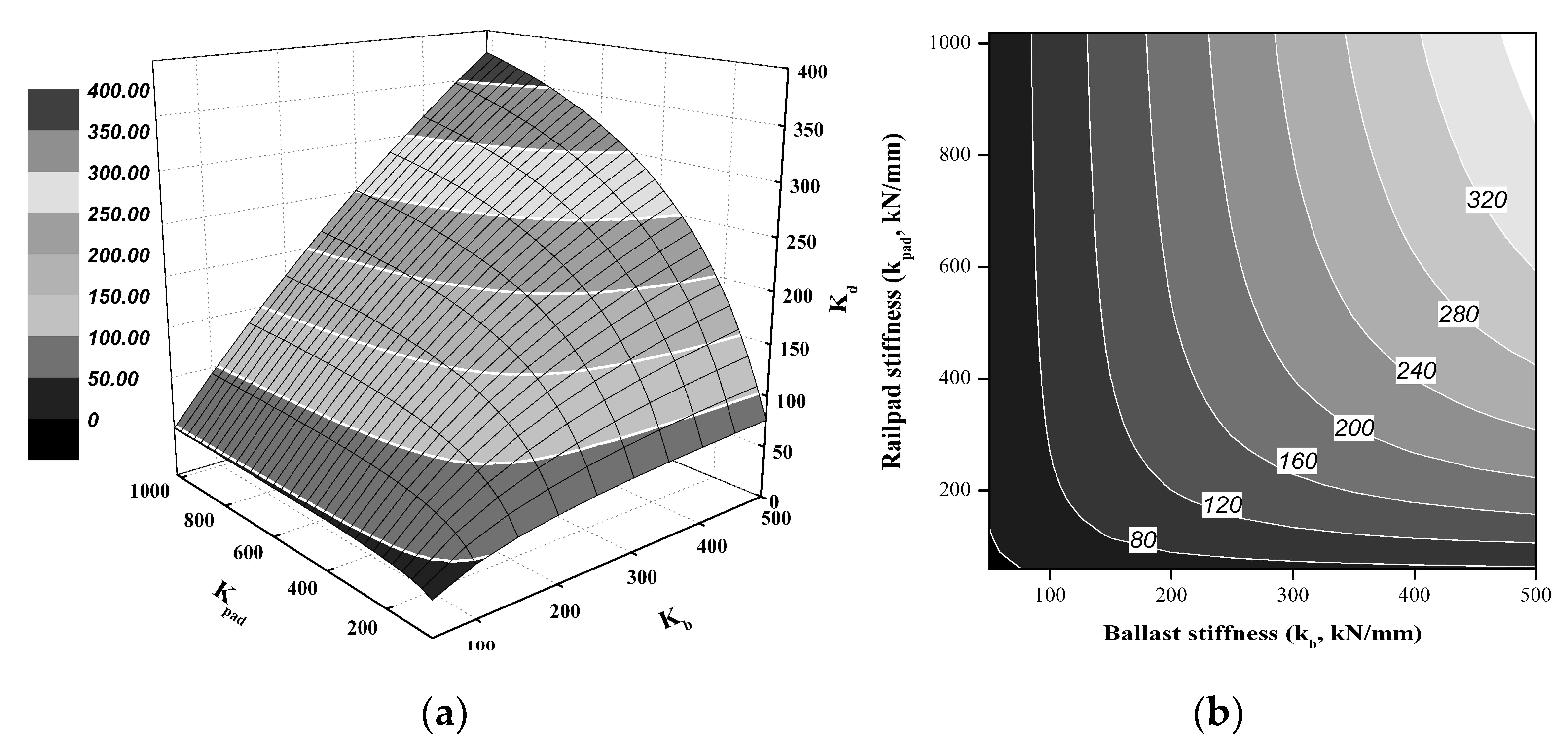
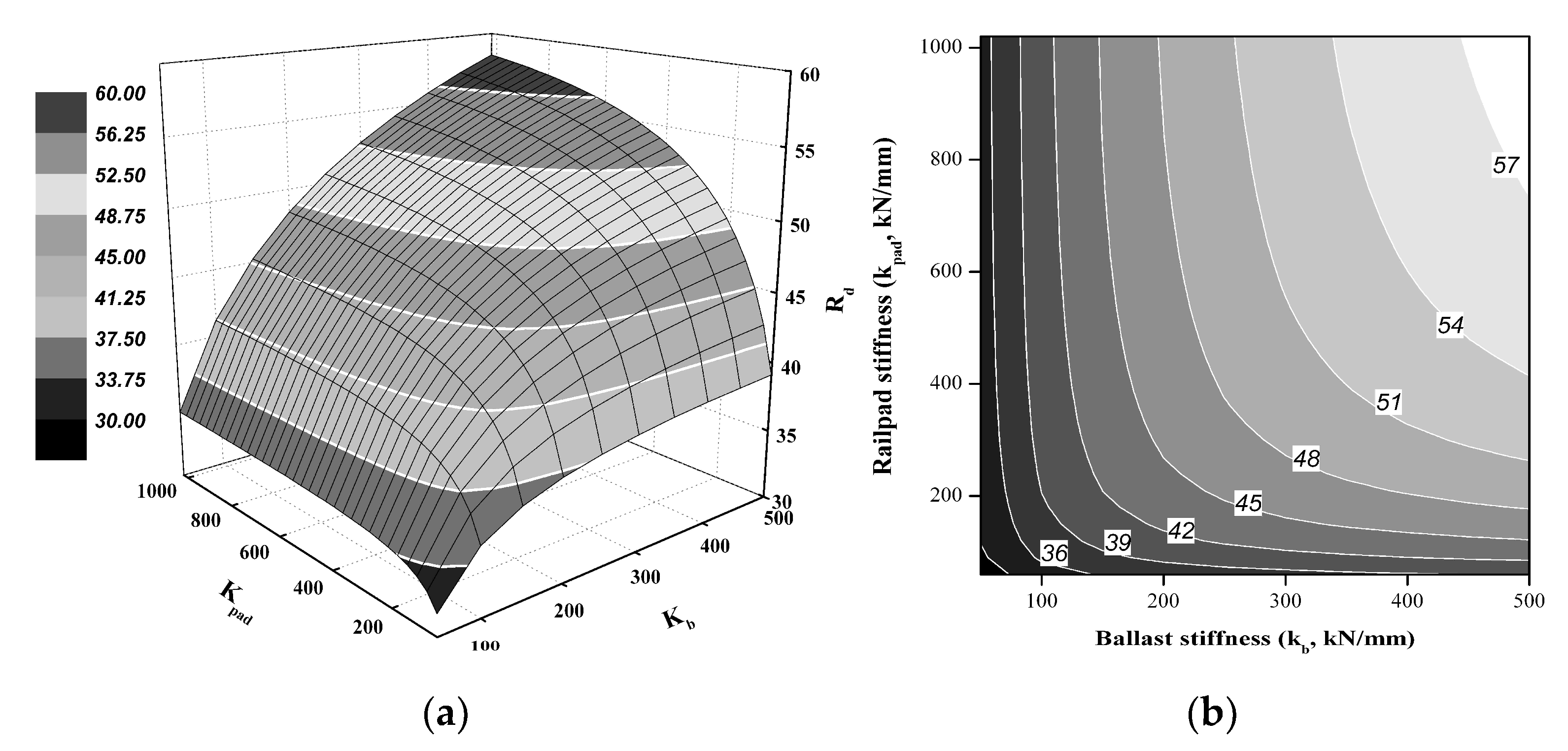
In the graph on the right side of Figure 5 (flat graph), the figures in the white box on top of the white line represent the boundary values of each area. The rail support stiffness (kd) increased with increasing rail pad stiffness (kpad) and ballast stiffness (kb), as is clear from the top-view of Figure 5a presented in Figure 5b. At a constant rail pad stiffness of kpad = 400 kN/mm, which is the normal thermoplastic polyurethane (TPU) pad used in conventional ballasted railway lines in Korea, the rail support stiffness increased with increasing ballast stiffness. Due to the L-shaped nature of the iso-kd curves in the kpad–kb graph, at kb > 200 kN/mm, the rail support stiffness was more affected by the rail pad stiffness than the ballast stiffness. For example, at kb = 300 kN/mm, the rail support stiffness at kpad = 600 kN/mm was approximately 1.2 times greater than that at kpad = 400 kN/mm.
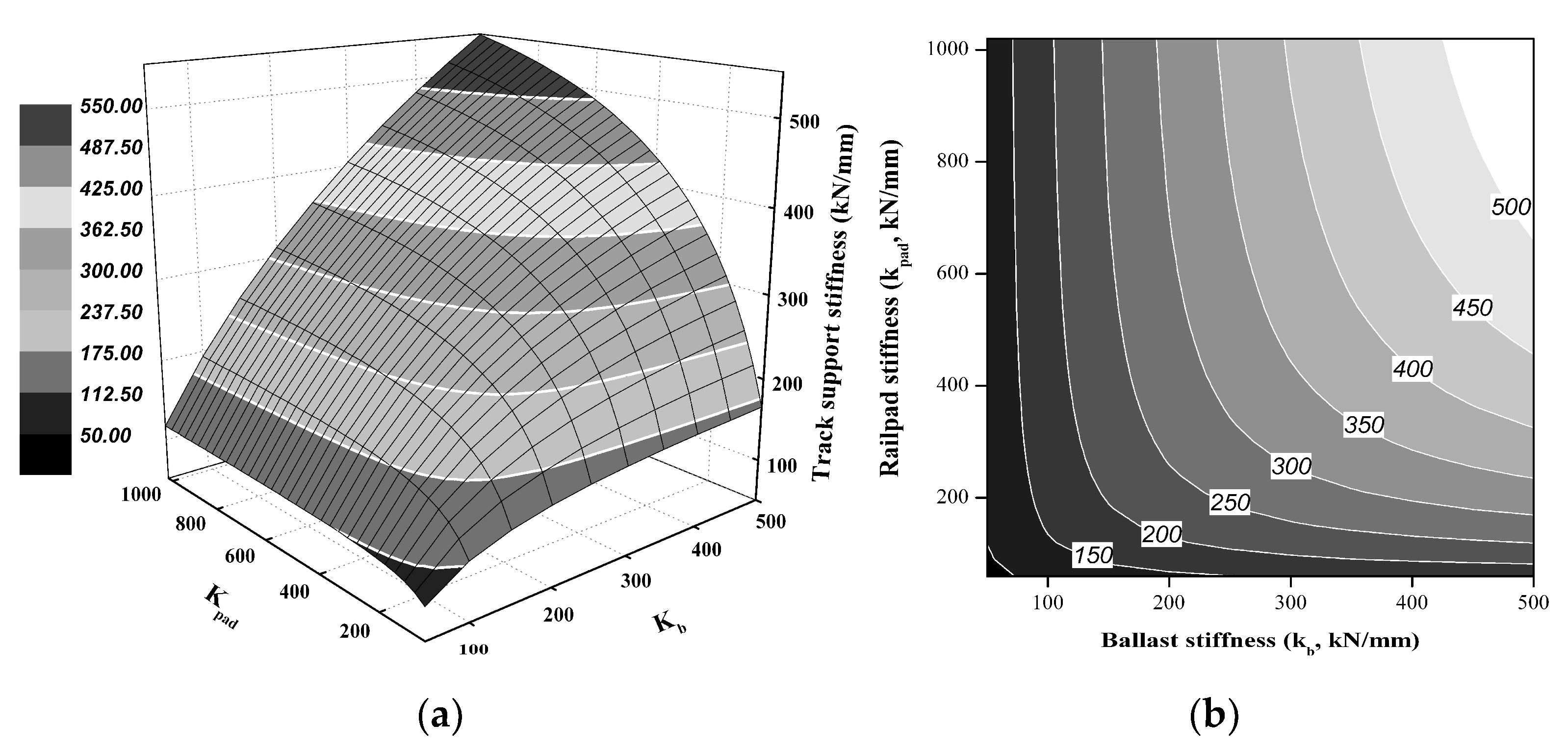
The track support stiffness also increased with increasing rail pad stiffness and ballast stiffness, as demonstrated in Figure 6. At a constant rail pad stiffness of kpad = 400 kN/mm, the track support stiffness increased with increasing ballast stiffness. Due to the L-shaped nature of the isotrack support stiffness curves in the kpad–kb graph, at kb > 300 kN/mm, the track support stiffness was more affected by the rail pad stiffness than the ballast stiffness. For example, at kb = 300 kN/mm, the track support stiffness at kpad = 600 kN/mm was approximately 1.4 times greater than that at kpad = 400 kN/mm. Moreover, at kb = 200 kN/mm, the track support stiffness was similar to the rail pad stiffness at both 400 and 600 kN/mm.
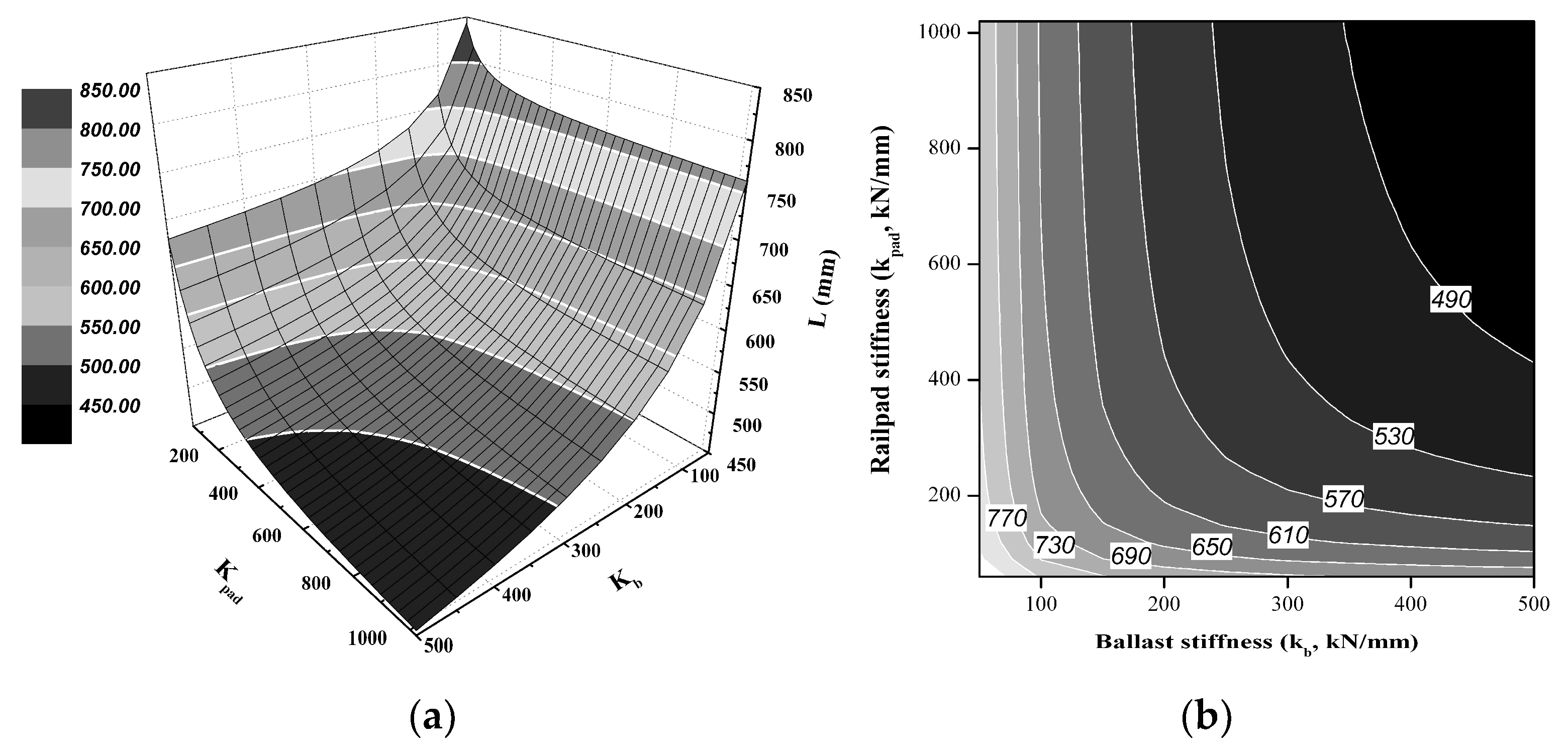
The characteristic track length decreased with increasing rail pad and ballast stiffness, as shown in Figure 7. At a constant rail pad stiffness of kpad = 400 kN/mm, the characteristic track length decreased with increasing ballast stiffness. Therefore, to allow for an increasing rail pad stiffness while ensuring that the characteristic track length is similar to the sleeper spacing, i.e., the Korean conventional ballasted track of 588–625 mm, the ballast stiffness was held between 200 and 300 kN/mm while varying the rail pad stiffness.
As the characteristic track length directly depends on the rail bending and support stiffness and affects the track displacement and rail bending stress, it may also affect the secondary track settlement and rail corrugation.
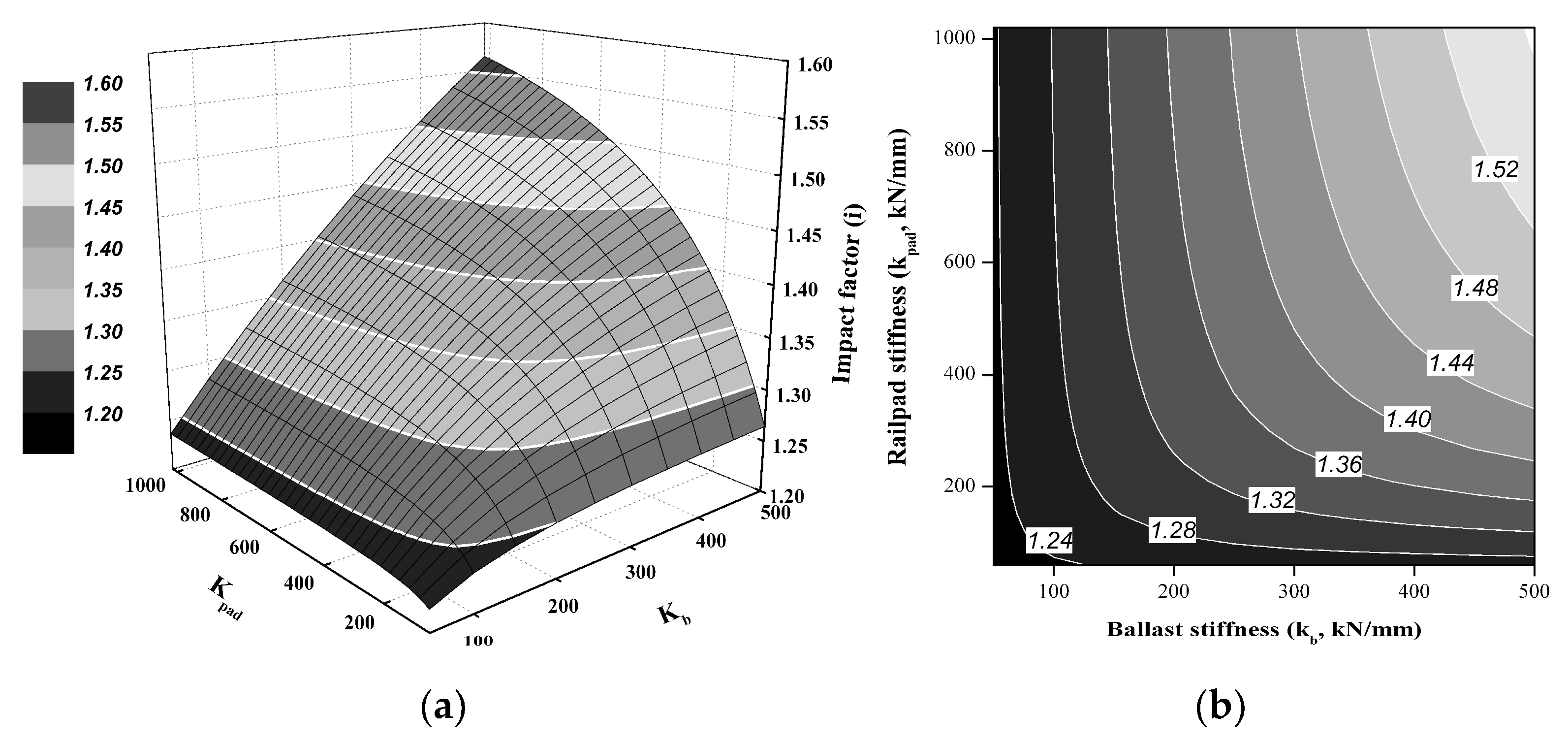
The track impact factor also increased with increasing rail pad and ballast stiffness, as shown in Figure 8, although the ballast stiffness affected the track impact factor more strongly than the rail pad stiffness. For standard Korean track designs, the track impact factor is recommended to remain within a very narrow range of 1.410–1.513 (train speed of 80–100 km/h). To ensure that the track impact factor did not exceed this initial design value, the ballast stiffness was held constant at 200–300 kN/mm while varying the rail pad stiffness, track condition, and rail surface roughness. At a constant rail pad stiffness of kpad = 400 kN/mm, increasing the ballast stiffness also caused the track impact factor to increase.
The ballast is the only elastic spring material in a ballasted track, and its elasticity reduces with time. Therefore, an appropriate track support stiffness, which is affected by the rail pad and ballast stiffness, must be selected to prevent the track impact factor from exceeding the design specifications.
4.2. Assessment of the Dynamic Track Responses Using Qualitative Analysis
The resulting variations in dynamic track response plotted against the variation in the rail and ballast stiffness at a vehicle speed of 120 km/h are shown in Figure 9, Figure 10, Figure 11 and Figure 12. The sleeper reaction force may directly affect the track displacement, rail support pressure, and track deterioration, and thus was determined to depend upon the track support stiffness, rail displacement, and rail bending stiffness.
The sleeper reaction force increased with increasing rail pad and ballast stiffness, as shown in Figure 9. At a constant rail pad stiffness of kpad = 400 kN/mm, increasing the ballast stiffness caused the sleeper reaction force to increase. Furthermore, the sleeper reaction force was more affected by the ballast stiffness than the rail pad stiffness. For example, at kpad = 400 kN/mm, the sleeper reaction force at a of kb = 300 kN/mm was approximately 1.1 times greater than that at kb = 200 kN/mm. Generally, sleeper reaction forces account for 60% of the dynamic wheel load [1,2,4,13]. However, in that case, the majority of the sleeper reaction force could be ensuring that 60% of the dynamic wheel load at the ballast stiffness of 400 kN/mm.
The relationship between the rail displacement, which directly affects the track displacement, passenger comfort, and track deterioration, and the track support stiffness, characteristic track length, dynamic wheel load, and rail bending stiffness was then investigated.
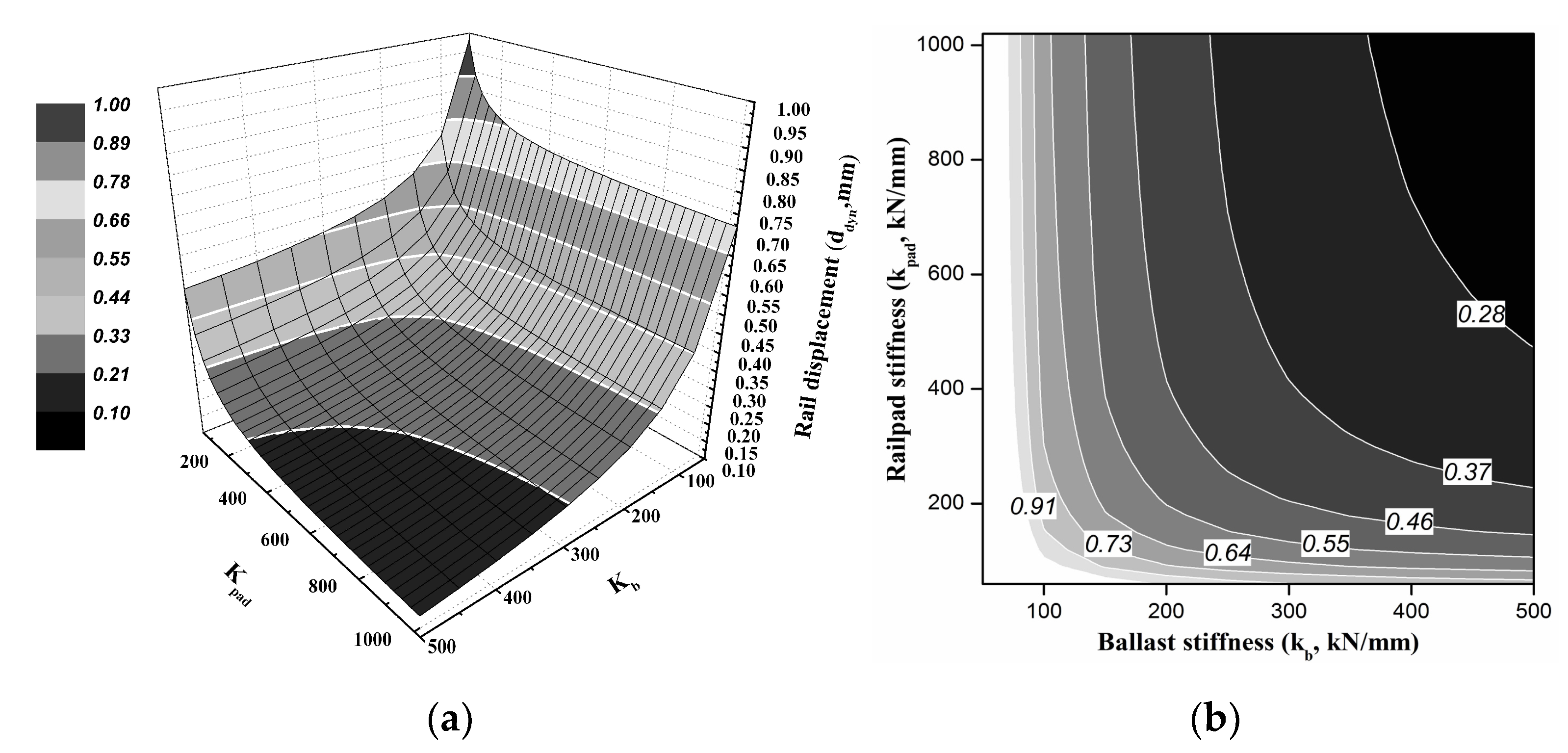
The rail displacement was found to decrease with increasing rail pad and ballast stiffness, as shown in Figure 10, although the ballast stiffness did affect the rail displacement more strongly than the rail pad stiffness. In a classic ballasted track, low-average rail displacement of approximately 0.3–0.4 mm under a wheel load of 100 kN corresponds to a subgrade modulus of 0.3–0.5 N/mm³ [4]. Under Korean and German track regulation, the rail displacement must remain within the very narrow range of 1.2–1.5 mm for high-speed railway (HSR) lines.
However, the rail displacement of in-service ballasted tracks depends on the track components and ballast condition. To ensure that the rail displacement did not exceed the Korean regulatory limits during normal operation (0.4–0.5 mm), the ballast stiffness was held constant at 200–220 kN/mm while varying the rail pad stiffness from 400 to 600 kN/mm. At the constant rail pad stiffness of 400 kN/mm, increasing the ballast stiffness also caused the rail displacement to increase.
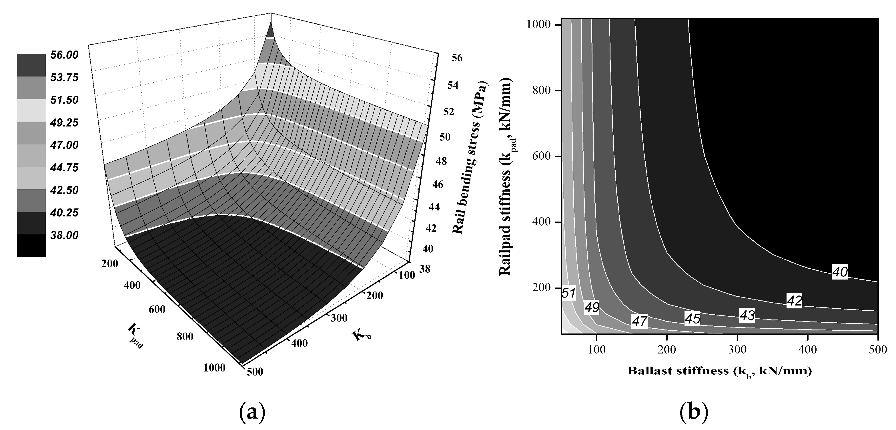
The relationship between the rail bending stress, which directly affects the track displacement and safety, and the track support stiffness, characteristic track length, dynamic wheel load, and rail bending stiffness, was then investigated. As a result, the rail bending stress decreased with increasing rail pad and ballast stiffness, as shown in Figure 11, although the ballast stiffness affected the rail bending stress more strongly than the rail pad stiffness. Korean and German regulations require that the rail bending stress of the CWR for HSR lines remain lower than 92 and 70 MPa, respectively; however, others have recommended that the rail bending stress of a ballasted track on an HSR remain below 60 MPa [4]. However, in that case, most rail bending stress could be ensuring that of the Korean and German regulation regardless of increasing the ballast and rail pad stiffness. Therefore, allowing for an increasing stiffness of rail pad and ballast to ensure that the rail bending stress is satisfied with the Korean and German regulation, the rail displacement should be controlled by the regulation.
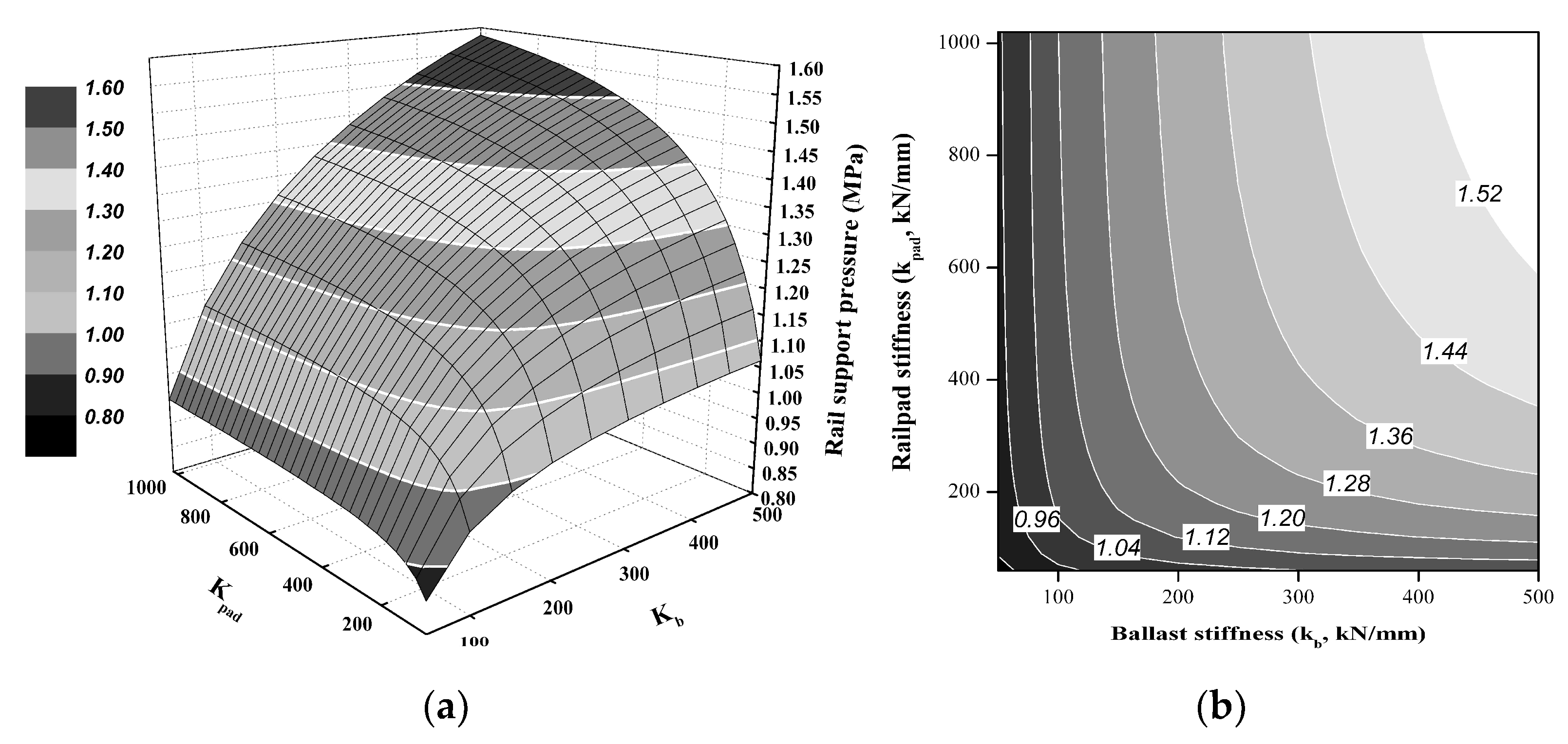
As the rail support pressure directly affects the rail pad and track deterioration, the relationship between the rail support pressure and the track support stiffness, rail displacement, and effective surface area of the rail pad was then investigated. To do so, a normal TPU pad used in Korean conventional ballasted railway lines was used, with an effective rail pad length, width, and surface area of 160, 230, and 36,800 mm2, respectively. The resulting variation in rail support pressure with rail pad and ballast stiffness is shown in Figure 12.
The results indicate that the rail support pressure increased with increasing rail pad and ballast stiffness, although the ballast stiffness affected the rail support pressure more strongly than the rail pad stiffness. The rail support force depended on the track support stiffness and was divided by the effective surface area of the rail pad. Therefore, the rail support pressure directly depends on the ballast stiffness, which was affect the track support stiffness. At a constant rail pad stiffness of 400 kN/mm, increasing the ballast stiffness also caused the rail support pressure to increase.
4.3. Validation of Proposed QPM
A qualitative dynamic behavior prediction model was proposed to predict and assess ballasted track performance as a function of dynamic vehicle loading and track support stiffness. To validate the proposed model, which consists of a 2DOF dynamic track model and modified track properties that define the rail pad and ballast stiffness ranges based on designed and measured values, field rail pad stiffness measurements were performed using a test track. A pandrol rail pad used in conventional Korean ballasted tracks was adopted according to the Korean standard (KS F2310). Seven rail pad specimens used for conventional ballasted tracks in South Korea were selected to measure the dynamic rail pad stiffness. Each specimen was in relatively good condition, and the dynamic rail pad stiffness was approximately 480–520 kN/mm.
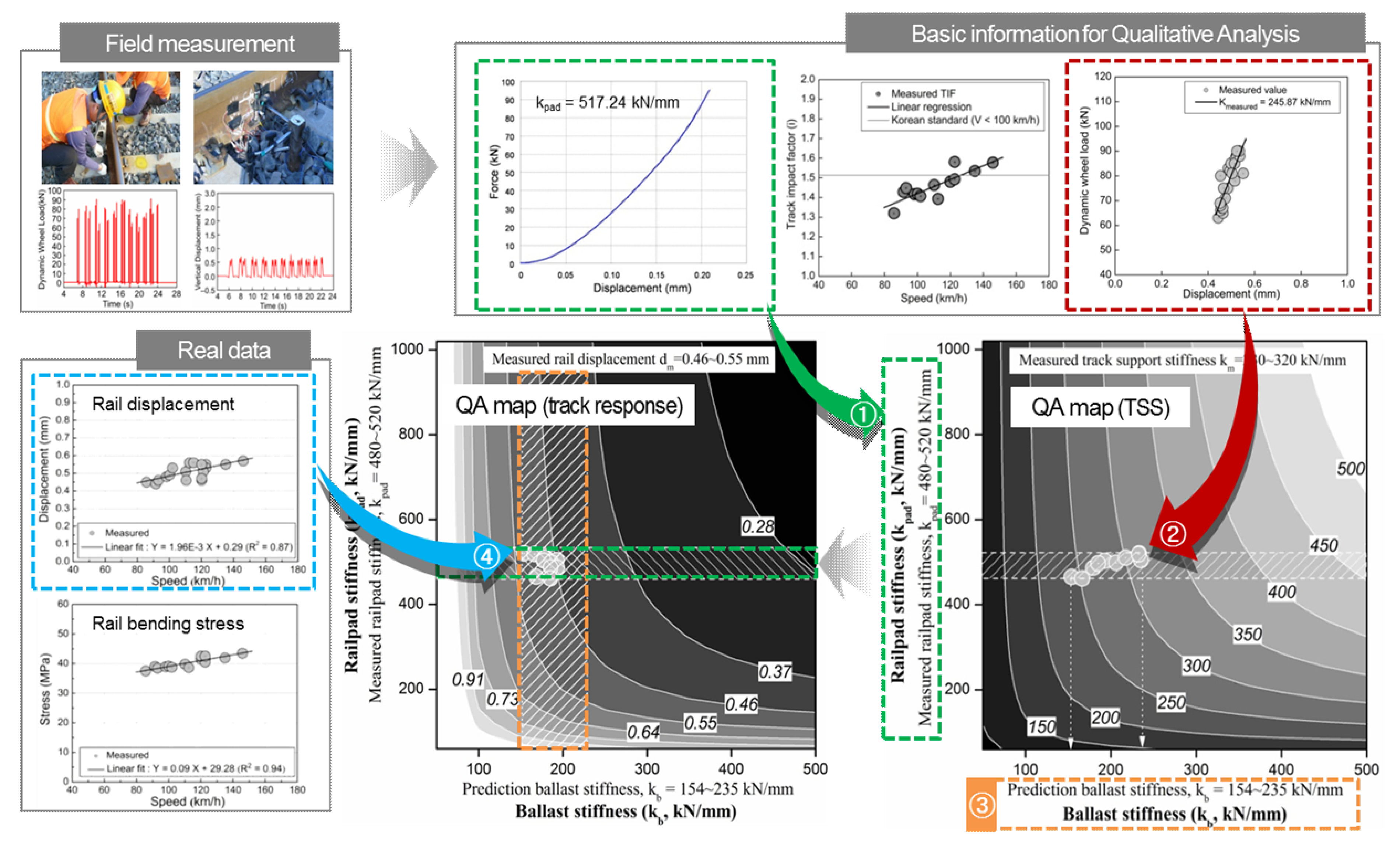
The proposed QPM is summarized in Figure 13. Using the assumed and measured data, including the measured rail pad stiffness, track support stiffness, and predicted ballast stiffness, the dynamic response of an in-service ballasted track can be predicted through the following four-step process.
- Step 1: Draw the measured data block (the rail pad stiffness, Figure 13 (①) in horizontal direction on the qualitative analysis map (track support stiffness (TSS) map).
- Step 3: Draw the blocks in both the vertical and horizontal directions on the qualitative analysis map (track response map). Then, check that the intersection region of a duplicated zone between the vertical and horizontal direction; this represents the predicted response of the in-service ballasted track.
- Step 4: Verify the range of the predicted results (value in white box) using the real response data obtained from the target track (circles in Figure 13 (④)) from the intersection region of the proposed qualitative analysis map.
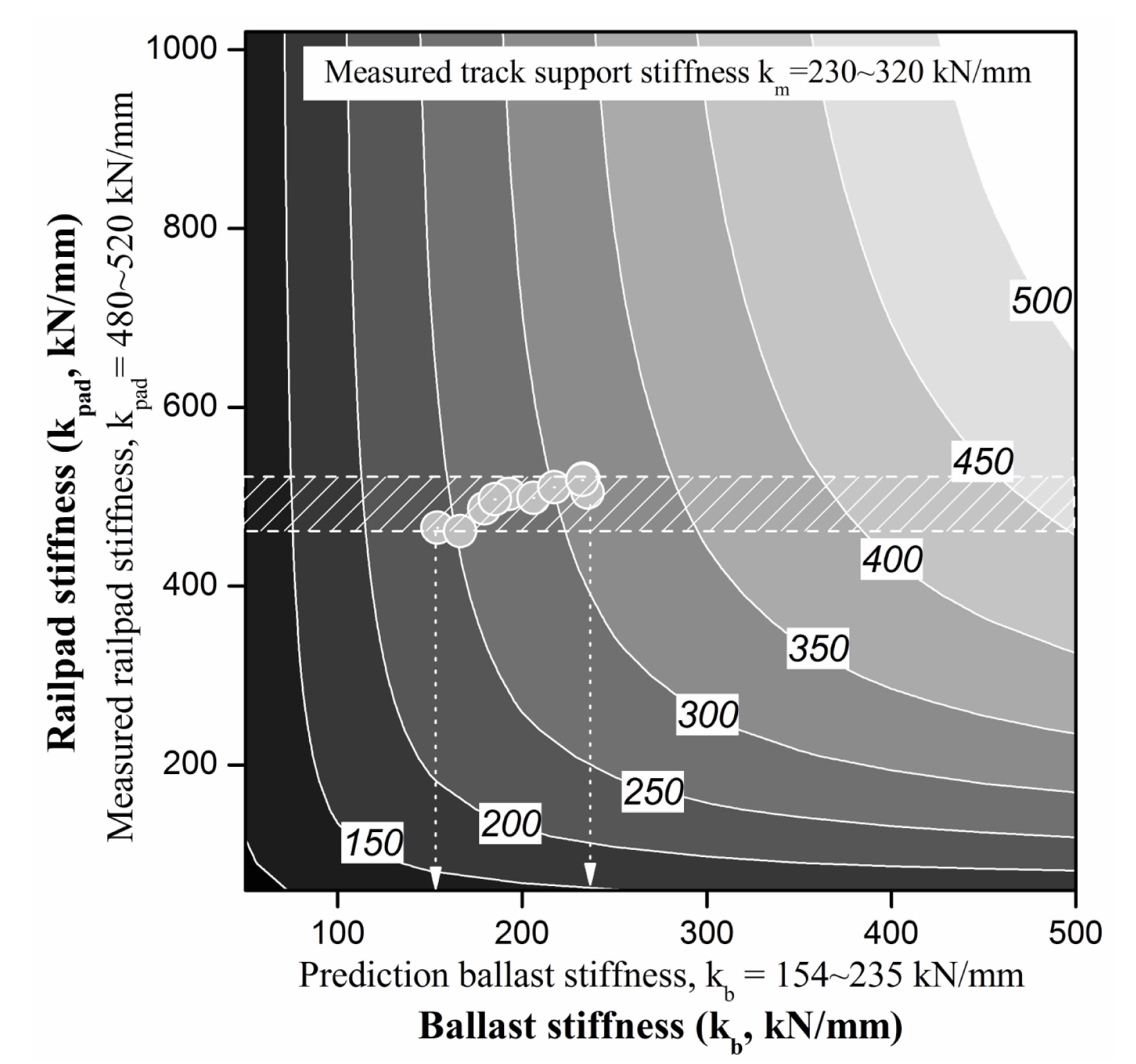
The TSS, rail displacement, and rail bending stress were then analyzed as dependent variables of the proposed qualitative analysis method. The measured rail pad stiffness and vehicle speed were 480–520 kN/mm and 120 km/h, respectively, and the measured TSS and rail displacement were defined as reference or guide data. The resulting TSS variation with the rail pad and ballast stiffness is summarized in Figure 14. The TSS of the in-service ballasted track was predicted from the intersection region of the duplicated zone between the vertical and horizontal direction, which represented the predicted response of the in-service ballasted track.
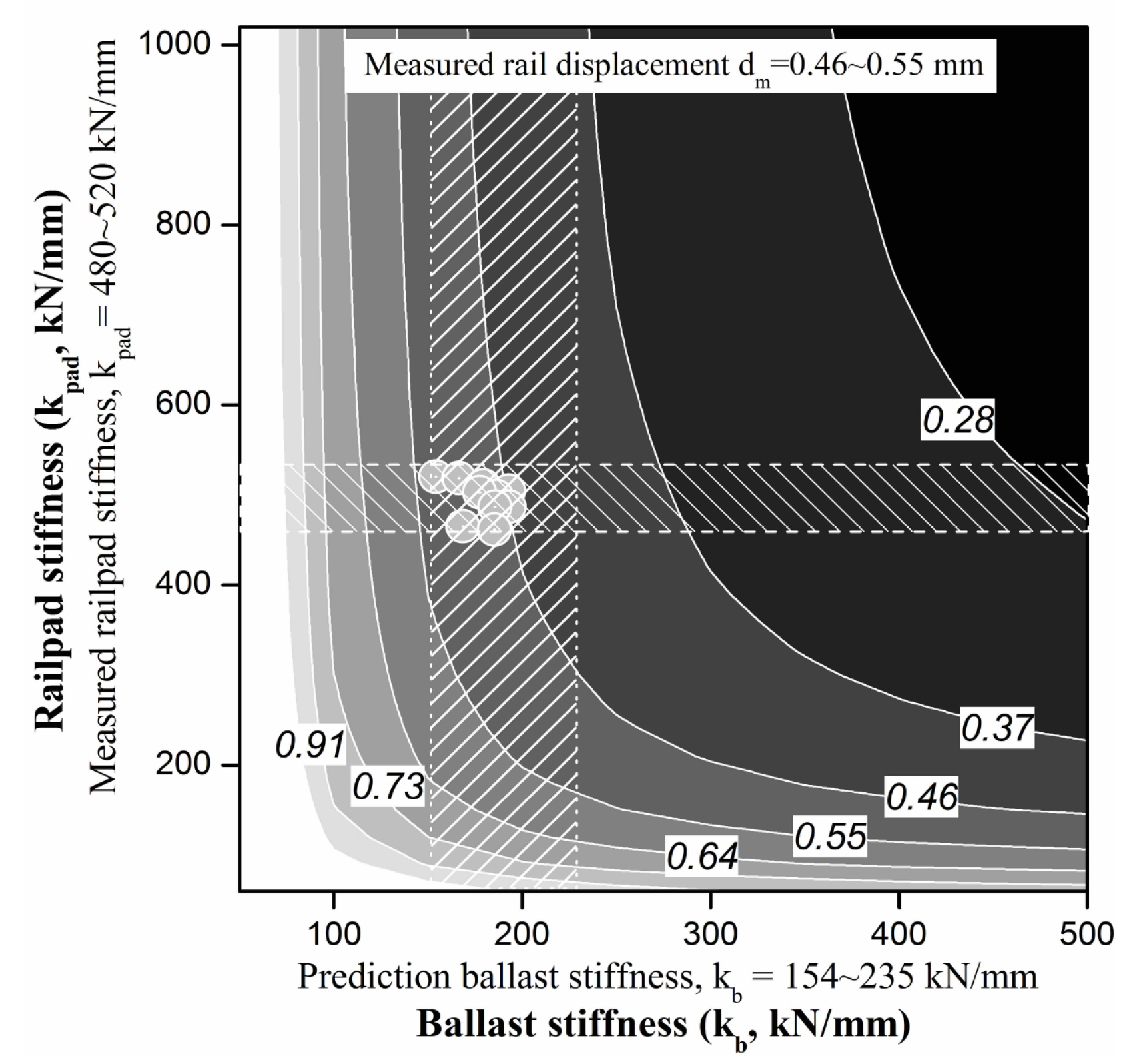
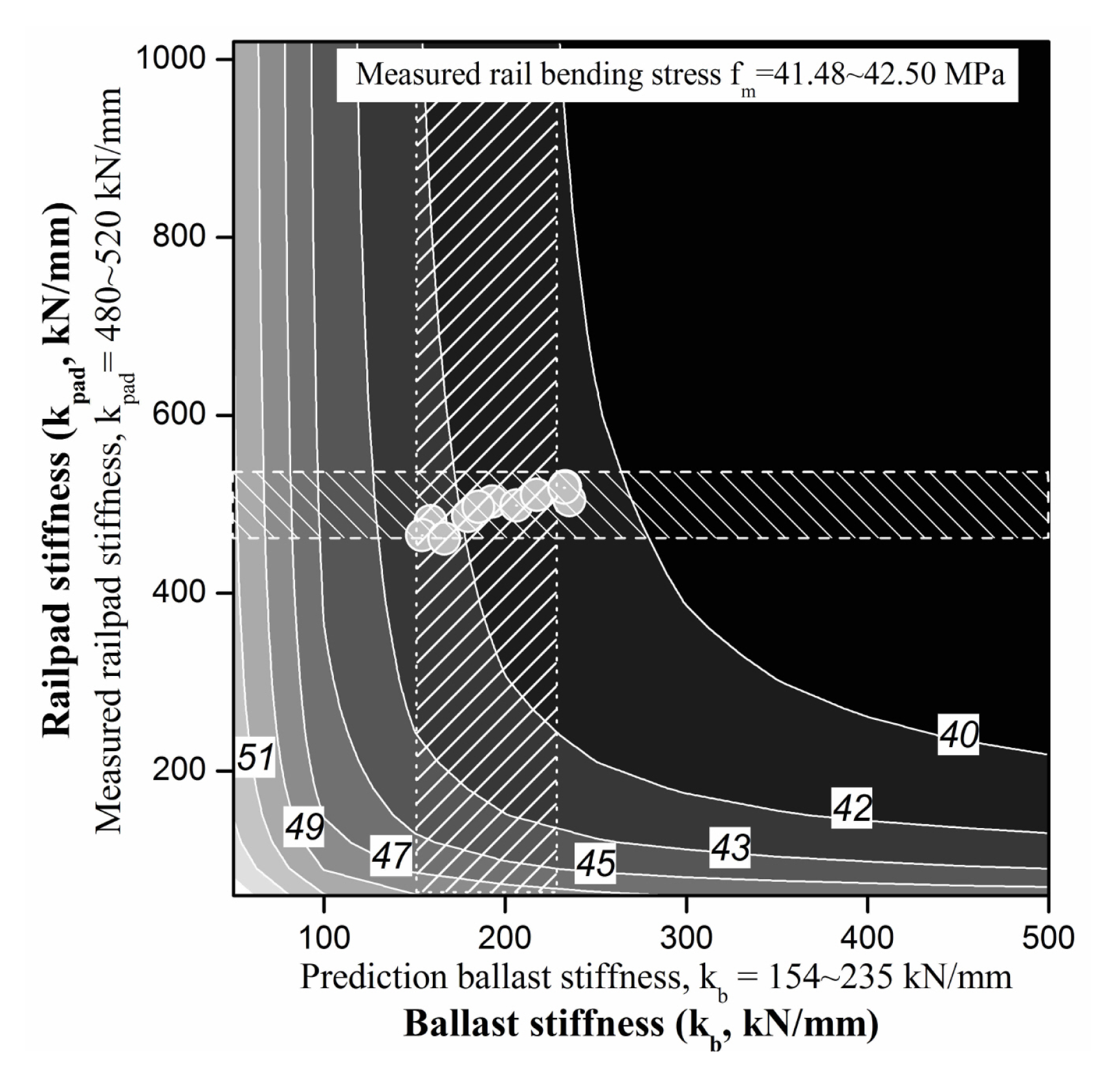
The predicted rail displacement and rail bending stress maps using the proposed qualitative analysis method are compared with the measured rail pad stiffness from chapter 3 in Figure 15 and Figure 16, respectively. The proposed model predicted the rail displacement and rail bending stress within approximately 2–5% of the obtained field measurement, thus validating the proposed method.
The results obtained using the proposed QPM thus verified the model and demonstrated that the obtained measured data, such as rail pad stiffness and dynamic TSS, are suitable for predicting the dynamic responses acting on a ballasted track and should thus be employed in track maintenance. The proposed model thus allows for the use of measured track responses to predict the responses and parameters of the ballasted track using a solution space. This study presents a statistical analysis of the measured results and provides a good understanding about the responses and response variation of a ballasted track. The proposed model can be used to help to provide acceptable TSS ranges, such as those related to the rail pad and ballast stiffness.
5. Conclusions
In this study, a QPM was proposed to predict and assess the performance of ballasted tracks as a function of dynamic wheel-rail force and variation in TSS. The results obtained are summarized below.
- (1)
- The ballasted track response should be a function of the variations in vertical spring stiffness of the rail pad or ballast. The QPM consists of a 2DOF dynamic track model and modified track properties, which define the rail pad and ballast stiffness ranges, based on designed and measured values. The proposed QPM is capable of simulating the complex interaction between the properties of track components and dynamic track responses.
- (2)
- The parameters and dynamic response of the ballasted track determined through field measurements and qualitative analysis showed that the TSS more strongly affects every parameter and is therefore more affected by ballast stiffness than by rail pad stiffness. A ballast stiffness of 200–300 kN/mm can reduce track deterioration (deflection and deformation) and dynamic response. Furthermore, an appropriate TSS is required to prevent exceeding the dynamic response of the in-service ballasted track, i.e., when the track forces, dynamic contribution, or vibration behavior is over the design specifications. The qualitative analysis results showed good agreement (within 2–5%) with the field measurement results.
- (3)
- The proposed QPM presents results as a discrete space of various track responses and parameters, rather than as of single values. The dynamic behavior of in-service ballasted tracks can thus be predicted qualitatively as a function of the rail pad and ballast stiffness using a simple field test and the proposed QPM.
- (4)
- Using the proposed QPM, a dynamic response map can be predicted and used to deal with uncertainties and design variables. The results of the qualitative analysis showed good agreement with field measurements and FE analysis results. The proposed QPM can predict the dynamic response of ballasted tracks using field-measured data, such as rail pad stiffness, rail bending stress, or rail displacement.
- (5)
- The dynamic track response obtained using qualitative analysis can be used to predict the constraint parameters determined by field measurements and should facilitate practical track maintenance operations. The proposed model thus allows for the use of measured track responses to predict the responses and parameters of the ballasted track using a solution space. Overall, the study successfully proposed a model to predict track field conditions and suitability for maintaining a ballasted track.
Author Contributions
J.-Y.C. contributed to conception and acquisition of data; J.-Y.C. and S.-H.K. investigated the data acquisition and formal analysis; J.-Y.C. and S.-H.K. wrote the paper; S.-H.K. critically revised the paper. All authors have read and agreed to the published version of the manuscript.
Funding
This research received no external funding.
Acknowledgments
This Study was supported by grant from Dong Yang University in 2019.
Conflicts of Interest
The authors declare no conflict of interest regarding the publication of this paper.
References
- Choi, J.Y. Qualitative Analysis for Dynamic Behavior of Railway Ballasted Track. Ph.D. Thesis, Technical University of Berlin, Berlin, Germany, 2014. [Google Scholar]
- Dahlberg, T. Railway Track Dynamics—A Survey; Linköping University: Linköping, Sweden, 2003; (unpublished). [Google Scholar]
- Esveld, C. Modern Railway Track, 2nd ed.; MRT-Productions: Zaltbommel, The Netherlands, 2001. [Google Scholar]
- Lichtberger, B. Track Compendium, 2nd ed.; Eurail Press: Hamburg, Germany, 2010. [Google Scholar]
- Cai, Z. Modelling of Rail Track Dynamics and Wheel/Rail Interaction. Ph.D. Thesis, Queen’s University, Kingston, ON, Canada, 1992. [Google Scholar]
- Choi, J.Y. Influence of track support stiffness of ballasted track on dynamic wheel-rail forces. J. Transp. Eng. ASCE 2013, 139, 709–718. [Google Scholar] [CrossRef]
- Hunt, G.A. Review of the Effect of Track Stiffness on Track Performance; Research Project T372, AEATR-II-2004–2018; Rail Safety and Standards Board: London, UK, 2005. [Google Scholar]
- Zhou, Y. Engineering Qualitative Analysis and Its Application on Fatigue Design Steel Structures. Ph.D. Thesis, University of British Columbia, Vancouver, BC, Canada, 2005. [Google Scholar]
- Li, M.X.D.; Berggren, E.G. A study of the effect of global track stiffness and its variations on track performance: Simulation and measurement. Proc. Inst. Mech. Eng. Part F 2010, 224, 375–382. [Google Scholar] [CrossRef]
- Li, M.X.D.; Berggren, E.G.; Berg, M. Assessment of vertical track geometry quality based on simulations of dynamic track-vehicle interaction. Proc. Inst. Mech. Eng. Part F 2009, 223, 131–139. [Google Scholar] [CrossRef]
- Li, M.X.D.; Ekevid, T.; Wiberg, N.E. An integrated vehicle–track-ground model for investigating the wheel/rail dynamic forces due to high axle loads. In Proceedings of the 6th International Conference on Contact Mechanics and Wear of Rail/Wheel Systems (CM2003), Gothenburg, Sweden, 10–13 June 2003; pp. 295–300. [Google Scholar]
- Zhou, Y.; Stiemer, S.F. Qualitative and Semi-Quantitative Analysis of Welding Distortion. In Proceedings of the Structural Specialty Conference of CSCE, Halifax, Nova Scotia, 10–13 June 1998. [Google Scholar]
- Fröhling, R.D. Deterioration of Railway Track due to Dynamic Vehicle Loading and Spatially Varying Stiffness. Ph.D. Thesis, University of Pretoria, Pretoria, South Africa, 2009. [Google Scholar]
- Graduate School of Railway, Seoul National University of Science and Technology. A Study on the Maintenance and Estimate of Fatigue Life for Used Rail; Seoul National University of Science and Technology: Seoul Metro, Korea, 2009. [Google Scholar]
- Kaewunruen, S.; Remennikov, A. Dynamic Properties of Railway Track and Its Components: A State-of-the-Art Review; University of Wollongong: New South Wales, Australia, 2008. [Google Scholar]
- Kaewunruen, S.; Remennikov, A. A State-of-the-Art Review Report on Vibration Testing of Ballasted Track Components; July-Dec Research Report; CRC Railway Engineering and Technologies: Rockhampton, Queensland, Australia, 2004. [Google Scholar]
- Kaewunruen, S.; Remennikov, A. Application of Experimental Modal Testing for Estimating Dynamic Properties of Structural Components. In Proceedings of the Australian Structural Engineering Conference 2005 (ASEC 2005), Newcastle, Australia, 1–14 September 2005. [Google Scholar]
- Kaewunruen, S.; Remennikov, A. In-Field Dynamic Testing and Measurements of Railway Tracks in Central Queensland; March-June Research Report; CRC Railway Engineering and Technologies: Rockhampton, Queensland, Australia, 2005. [Google Scholar]
- Kaewunruen, S.; Remennikov, A. Integrated field measurements and track simulations for condition assessment of railway tracks. In Proceedings of the 1st International Conference on Structural Condition Assessment, Monitoring, and Improvement, Perth, Australia, 12–14 December 2005; pp. 391–398. [Google Scholar]
- Kaewunruen, S.; Remennikov, A. Non-destructive evaluation for dynamic integrity of railway track structure. In Proceedings of the International Conference on Structural Integrity and Failure—SIF2006, Sydney, Australia, 27–29 September 2006; pp. 294–299. [Google Scholar]
- Kaewunruen, S.; Remennikov, A.M. Non-Destructive Testing (NDT): A Tool for Dynamic Health Monitoring of Railway Track Structures; Materials Australia: North Melbourne, Australia, 2006; Volume 39, pp. 14–16. [Google Scholar]
- Kaewunruen, S.; Remennikov, A. Field trials for dynamic characteristics of railway track and its components using impact excitation technique. NDT E Int. 2007, 40, 510–519. [Google Scholar] [CrossRef]
- Wu, T.X.; Thompson, D.J. The effects of local preload on the foundation stiffness and vertical vibration of railway track. J. Sound Vib. 1999, 219, 881–904. [Google Scholar] [CrossRef]
- Ngamkhanong, C.; Kaewunruen, S.; Afonso Costa, B.J. State-of-the-art review of railway track resilience monitoring. Infrastructures 2018, 3, 3. [Google Scholar] [CrossRef] [Green Version]
- Ngamkhanon, C.; Goto, K.; Kaewunruen, S. Dynamic responses of railway ballasted track considering rail pad deterioration. In Proceedings of the Modern Practice in Stress and Vibration Analysis (MPSVA) 2018, Cambridge, UK, 2–4 July 2018. [Google Scholar]
- Lim, N.H.; Kim, K.J.; Bae, H.U.; Kim, S.J. DEM analysis of track ballast for track ballast-wheel interaction simulation. Appl. Sci. 2020, 10, 2717. [Google Scholar] [CrossRef] [Green Version]
- Tsunashima, H. Condition monitoring of railway tracks from car-body vibration using a macine learning technique. Appl. Sci. 2019, 9, 2734. [Google Scholar] [CrossRef] [Green Version]
- Wang, H.; Silvast, M.; Markine, V.; Wiljanen, B. Analysis of the dynamic wheel loads in railway transition zones considering the moisture condition of the ballast and subballast. Appl. Sci. 2017, 7, 1208. [Google Scholar] [CrossRef] [Green Version]
- Zbiciak, A.; Kra’skiewicz, C.; Sabouni-Zawadzka, A.; Pełczyński, J.; Dudziak, S. A novel approach to the analysis of under sleeper pads (USP) applied in the ballasted track structures. Materials 2020, 13, 2438. [Google Scholar] [CrossRef]
- Sayeed, M.A.; Shahin, M.A. Design of ballasted railway track foundations using numerical modelling. Part I: Development. Can. Geotech. J. 2018, 55, 353–368. [Google Scholar] [CrossRef] [Green Version]
- Esmaeili, M.; Amiri, S.; Jadidi, K. An investigation into the use of asphalt layers to control stress and stain levels in railway track foundations. Proc. Inst. Mech. Eng. Park F J. Rail Rapid Transit 2014, 228, 182–193. [Google Scholar] [CrossRef]
- Weston, P.; Roberts, C.; Yeo, G.; Stewart, E. Perspectives on railway track geometry condition monitoring from in-service railway vehicles. Int. J. Veh. Mech. Mobil. 2015, 53, 1063–1091. [Google Scholar] [CrossRef]
- Marsella, M.; Scaioni, M. Sensors for deformation monitoring of large civil infrastructures. Sensors 2018, 18, 3941. [Google Scholar] [CrossRef] [PubMed] [Green Version]
- Montanari, U. Networks of constraints: Fundamental properties and applications to picture process. Inf. Sci. 1974, 7, 95–132. [Google Scholar] [CrossRef]
- Tsang, E. Foundation of Constraint Satisfaction; Academic Press: San Diego, CA, USA, 1993. [Google Scholar]
- Gedig, M.H. A framework for qualitative and semi-quantitative analysis in engineering design and evaluation. Master’s Thesis, University of British Columbia, Vancouver, BC, Canada, 1995. [Google Scholar]
- Mackworth, A. Consistency in networks of relations. Artif. Intell. 1977, 8, 99–118. [Google Scholar] [CrossRef]
- Moore, R.E. Interval Analysis; Prentice Hall: Englewood Cliffs, NJ, USA, 1966. [Google Scholar]
- Grassie, S.L.; Cox, S.J. The dynamic response of railway track with flexible sleepers to high frequency vertical excitation. Proc. Inst. Mech. Eng. Part D 1984, 198, 117–124. [Google Scholar] [CrossRef]
- Sadeghi, J. Investigation of Characteristics and Modeling of Railway Track System. Ph.D. Thesis, The University of Wollongong, Northfields Ave Wollongong, Australia, 1997. [Google Scholar]
- Oakdale Engineering. DataFit User’s Manual; Oakdale Engineering: Oakdale, PA, USA, 2005. [Google Scholar]
- Knothe, K.; Grassie, S. Modelling of railway track and vehicle/track interaction at high frequencies. Veh. Syst. Dyn. 1993, 22, 209–262. [Google Scholar] [CrossRef]
- Knothe, K.; Wu, Y. Receptance behaviour of railway track and subgrade. Arch. Appl. Mech. 1998, 68, 457–470. [Google Scholar] [CrossRef]
- Costa, P.A.; Calçada, R.; Cardoso, A.S.; Bodare, A. Influence of soil non-linearity on the dynamic response of high-speed railway tracks. Soil Dyn. Earthq. Eng. 2010, 30, 221–235. [Google Scholar] [CrossRef]
- Choi, J.Y.; Lee, D.W.; Park, Y.G. A study on the evaluation of track support stiffness on the various track type in urban transit. J. Korean Soc. Railw. 2011, 14, 262–270. [Google Scholar]
- Choi, J.Y.; Park, Y.G.; Lee, S.M. The evaluation of track impact factor on the various track type in urban transit. J. Korean Soc. Railw. 2011, 14, 248–255. [Google Scholar] [CrossRef]
- Man, A.P. Determination of dynamic track properties by means of excitation hammer testing. In Railway Engineering International 1996, 4th ed.; De Rooi Publications: Veenendaal, The Netherlands, 1996; pp. 8–9. [Google Scholar]
- Question D71, Stresses in the Track, Ballast and Formation as a Result of Rolling Loads, Stresses in Rails, Part 2: Calibration and Measuring Procedures; Report No. 1; International Union of Railways Office for Research and Experiments: Utrecht, The Netherlands, 1965.
- Korea Rail Network Authority. Railroad Track Design Standard, Part: Subgrade; Korea Rail Network Authority: Daejeon, Korea, 2011. (In Korean) [Google Scholar]
- Korea Rail Network Authority. Railroad Track Design Standard, Part: Track; Korea Rail Network Authority: Daejeon, Korea, 2011. (In Korean) [Google Scholar]
- Korea Railroad Research Institute. Evaluation for Stability of Track-Subgrade by Improving Speedup in the Gyeongchun Line; Korea Rail Network Authority (KR): Daejeon, Korea, 2009. (In Korean) [Google Scholar]
- Remennikov, A.M.; Kaewunruen, S. A review on loading conditions for railway track structures due to wheel and rail vertical interactions. Struct. Eng. Health Monit. 2008, 15, 207–234. [Google Scholar] [CrossRef]
Figure 1.
Ballasted track model.

Figure 2.
Photographs of the (a) track and (b) electric multiple unit (EMU) used for field measurements; (c) the vehicle load composition of the EMU.
Figure 2.
Photographs of the (a) track and (b) electric multiple unit (EMU) used for field measurements; (c) the vehicle load composition of the EMU.

Figure 3.
Photographs of wheel load sensor, strain gauges, and linear variable differential transformers (LVDTs) used to measure the (a) wheel load and rail bending stress; (b) rail and sleeper displacement.
Figure 3.
Photographs of wheel load sensor, strain gauges, and linear variable differential transformers (LVDTs) used to measure the (a) wheel load and rail bending stress; (b) rail and sleeper displacement.

Figure 4.
Variations in the dynamic response of the ballasted test track as a function of train velocity: (a) dynamic wheel load; (b) rail displacement; (c) sleeper displacement; (d) rail bending stress.
Figure 4.
Variations in the dynamic response of the ballasted test track as a function of train velocity: (a) dynamic wheel load; (b) rail displacement; (c) sleeper displacement; (d) rail bending stress.

Figure 5.
Example dynamic rail support stiffness as a function of rail pad and ballast stiffness: (a) 3D map; (b) 2D map.
Figure 5.
Example dynamic rail support stiffness as a function of rail pad and ballast stiffness: (a) 3D map; (b) 2D map.

Figure 6.
Example dynamic track support stiffness as a function of rail pad and ballast stiffness: (a) 3D map; (b) 2D map.
Figure 6.
Example dynamic track support stiffness as a function of rail pad and ballast stiffness: (a) 3D map; (b) 2D map.

Figure 7.
Example characteristic track length as a function of rail pad and ballast stiffness: (a) 3D map; (b) 2D map.
Figure 7.
Example characteristic track length as a function of rail pad and ballast stiffness: (a) 3D map; (b) 2D map.

Figure 8.
Example track impact factor as a function of rail pad and ballast stiffness (a) 3D map; (b) 2D map.
Figure 8.
Example track impact factor as a function of rail pad and ballast stiffness (a) 3D map; (b) 2D map.

Figure 9.
Example dynamic sleeper reaction force as a function of rail pad and ballast stiffness (a) 3D map; (b) 2D map.
Figure 9.
Example dynamic sleeper reaction force as a function of rail pad and ballast stiffness (a) 3D map; (b) 2D map.

Figure 10.
Example dynamic rail displacement as a function of rail pad and ballast stiffness (a) 3D map; (b) 2D map.
Figure 10.
Example dynamic rail displacement as a function of rail pad and ballast stiffness (a) 3D map; (b) 2D map.

Figure 11.
Example dynamic rail bending stress as a function of rail pad and ballast stiffness: (a) 3D map; (b) 2D map.
Figure 11.
Example dynamic rail bending stress as a function of rail pad and ballast stiffness: (a) 3D map; (b) 2D map.

Figure 12.
Example dynamic rail support pressure as a function of rail pad and ballast stiffness: (a) 3D map; (b) 2D map.
Figure 12.
Example dynamic rail support pressure as a function of rail pad and ballast stiffness: (a) 3D map; (b) 2D map.

Figure 13.
Process for using the qualitative prediction model (QPM) to predict a dynamic track response.
Figure 13.
Process for using the qualitative prediction model (QPM) to predict a dynamic track response.

Figure 14.
Track support stiffness (TSS) map of ballasted track using field measurements (circles) qualitative analysis, measured rail pad stiffness, and predicted ballast stiffness.
Figure 14.
Track support stiffness (TSS) map of ballasted track using field measurements (circles) qualitative analysis, measured rail pad stiffness, and predicted ballast stiffness.

Figure 15.
Rail displacement estimated using qualitative analysis, measured rail pad stiffness, and predicted ballast stiffness.
Figure 15.
Rail displacement estimated using qualitative analysis, measured rail pad stiffness, and predicted ballast stiffness.

Figure 16.
Rail bending stress estimated using field measurements, qualitative analysis, measured rail pad stiffness, and predicted ballast stiffness.
Figure 16.
Rail bending stress estimated using field measurements, qualitative analysis, measured rail pad stiffness, and predicted ballast stiffness.


Table 1.
Properties of the track components used in the proposed qualitative analysis.
| Properties | Rail (60 kg/m) | Prestressed Concrete Sleeper | |
|---|---|---|---|
| Section Properties | Cross-sectional area (cm2) | 77.5 | 516.75 |
| Moment of inertia (cm4) | 3090 | 16,375 | |
| Section modulus (cm3) | 396 | – | |
| Supported area of half-sleeper (cm2) | – | 3021 | |
| Material Properties | Elastic modulus (kN/cm2) | 21,000 | 4000 |
| Weight density (kN/cm3) | 7.85 × 10⁻⁵ | 2.5 × 10⁻⁵ | |
| Poisson’s ratio (υ) | 0.30 | 0.18 | |
Table 2.
Parameters of the ballasted track used in the proposed qualitative analysis.
| Description | Properties |
|---|---|
| Track curvature (R) | ∞ (Straight) |
| Cant | 0 mm |
| Substructure | Earthwork |
| Subgrade modulus a | 0.15 N/mm³ |
| Rail | 60 kg N, Continuous welded rail |
| Sleeper | 250 kg, Prestressed concrete sleeper |
| Sleeper spacing | 600 mm |
| Sleeper mass a | 250 kg |
| Fastening type | Pandrol e-clip |
| Rail pad a | Thermoplastic Polyurethane (TPU) pad |
| Rail pad stiffness a | 400 kN/mm |
| Rail pad damping coefficient b | 12.934 kNs/m |
| Ballast stiffness a | 200 kN/mm |
| Ballast damping coefficient b | 223.130 kNs/m |
| Ballast thickness (depth) | 300 mm |
| Ballast mat | – |
| Train type | EMU (electric multiple unit) |
| Wheelset mass (Mw) | 1025 kg |
| Static wheel load Q | 80 kN |
| Operational speed | Average 130 km/h |
a Value obtained from the design data book (Korean standard). b Value obtained from the field measurement (impact hammer test).
© 2020 by the authors. Licensee MDPI, Basel, Switzerland. This article is an open access article distributed under the terms and conditions of the Creative Commons Attribution (CC BY) license (http://creativecommons.org/licenses/by/4.0/).
Share and Cite
MDPI and ACS Style
Choi, J.-Y.; Kim, S.-H. Qualitative Prediction Model for Dynamic Behavior of Ballasted Tracks. Appl. Sci. 2020, 10, 6258. https://0-doi-org.brum.beds.ac.uk/10.3390/app10186258
AMA Style
Choi J-Y, Kim S-H. Qualitative Prediction Model for Dynamic Behavior of Ballasted Tracks. Applied Sciences. 2020; 10(18):6258. https://0-doi-org.brum.beds.ac.uk/10.3390/app10186258
Chicago/Turabian StyleChoi, Jung-Youl, and Sun-Hee Kim. 2020. "Qualitative Prediction Model for Dynamic Behavior of Ballasted Tracks" Applied Sciences 10, no. 18: 6258. https://0-doi-org.brum.beds.ac.uk/10.3390/app10186258
Note that from the first issue of 2016, this journal uses article numbers instead of page numbers. See further details here.