Validation of Support for Creation of License Drawings Using Application for openBIM-Based Automatic Generation of 2D Drawings


Abstract
:1. Introduction
2. Status and Literature Review
2.1. Theoretical Considerations of openBIM
2.2. Necessity for Automatic Generation of 2D Drawings
2.3. Automatic 2D Drawing Generation Program and Research Status
2.4. Domestic Licensing Status
2.5. Overseas Licensing Status
2.6. Result
3. Implementation of Automatic 2D Drawing Generation Program
3.1. Overview of Automatic 2D Drawing Generation Program
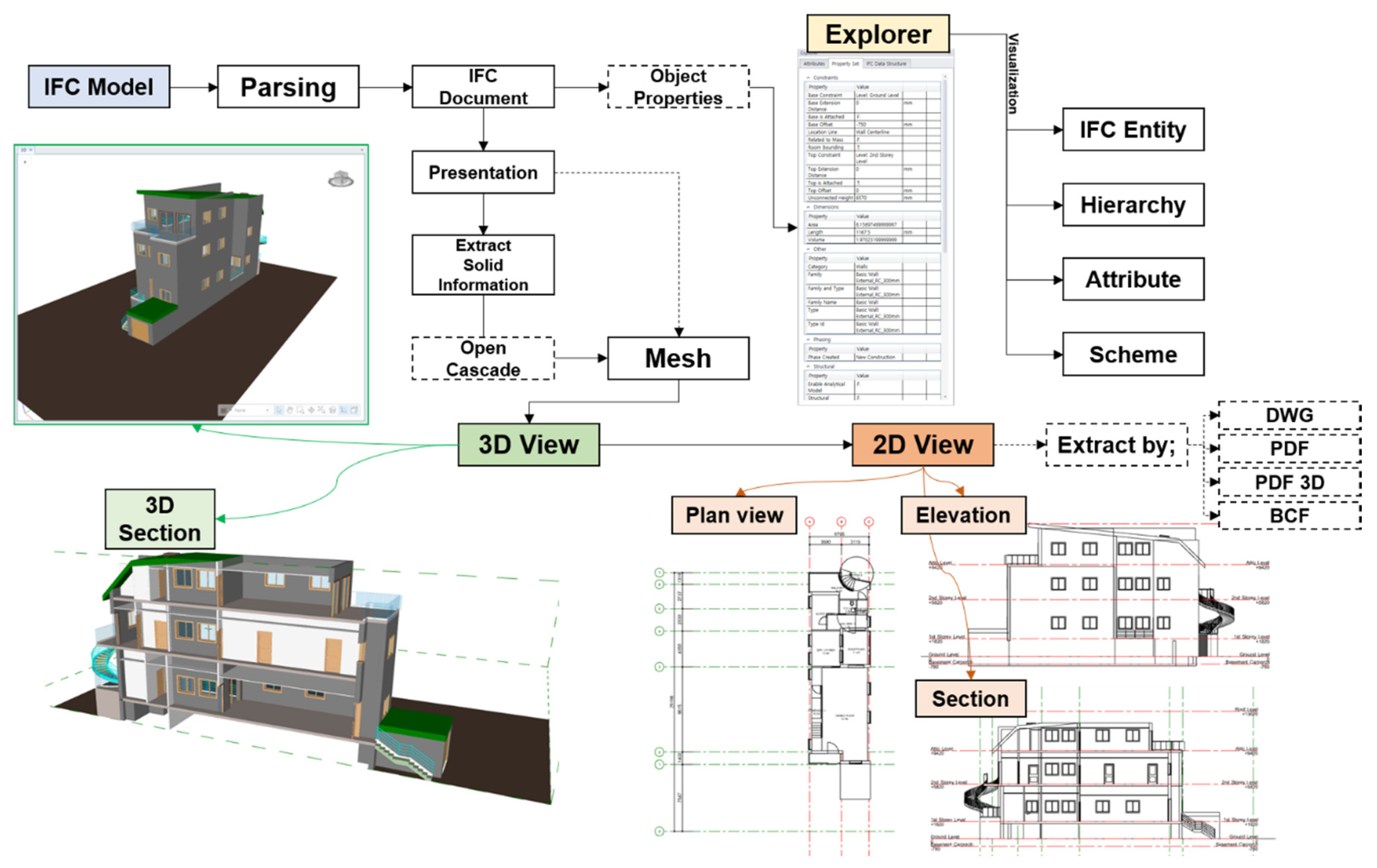
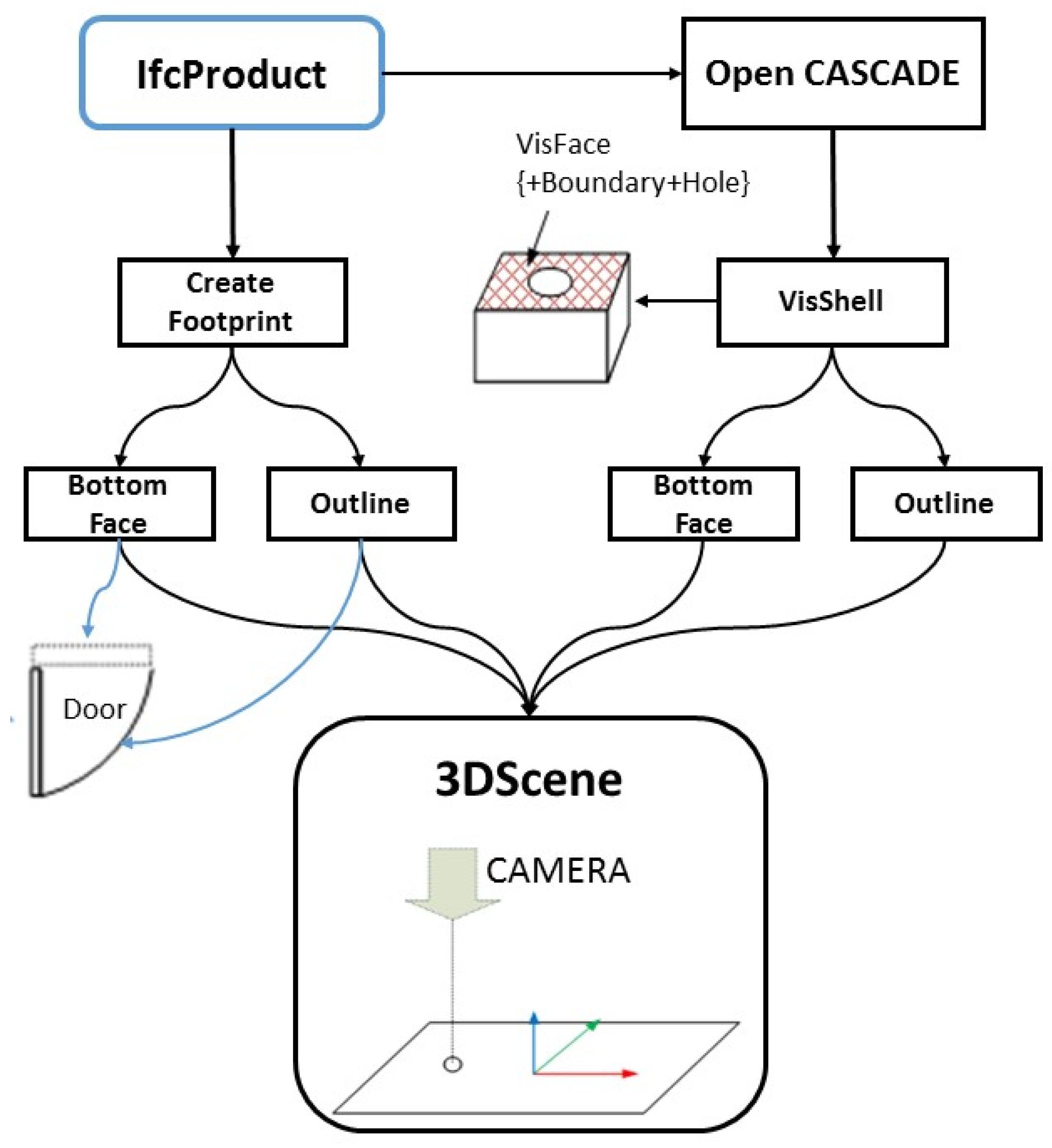
3.1.1. Overview of IFC-Based 2D Drawing Generation
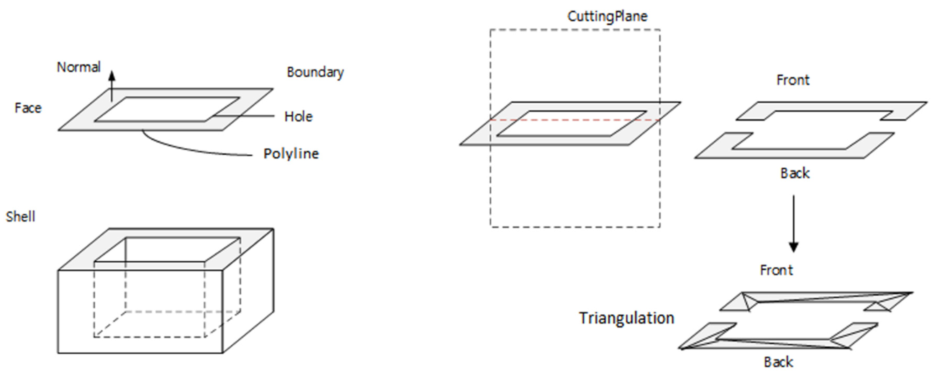
3.1.2. Object Shape Data Structure
3.2. Automatic Generation of 2D Drawings
Generation of Elevation, Section, and Plan View
- (1)
- Generation of elevation
- (2)
- Generation of section
- (i)
- The camera is positioned on the basis of coordinates of the cutting reference plane, and all objects intersected by the cutting plane perpendicular to the cross section are cut.
- (ii)
- The boundary line of the cut faces becomes the boundary line displayed on the screen.
- (3)
- Generation of floor plan
- (4)
- Annotation
- (5)
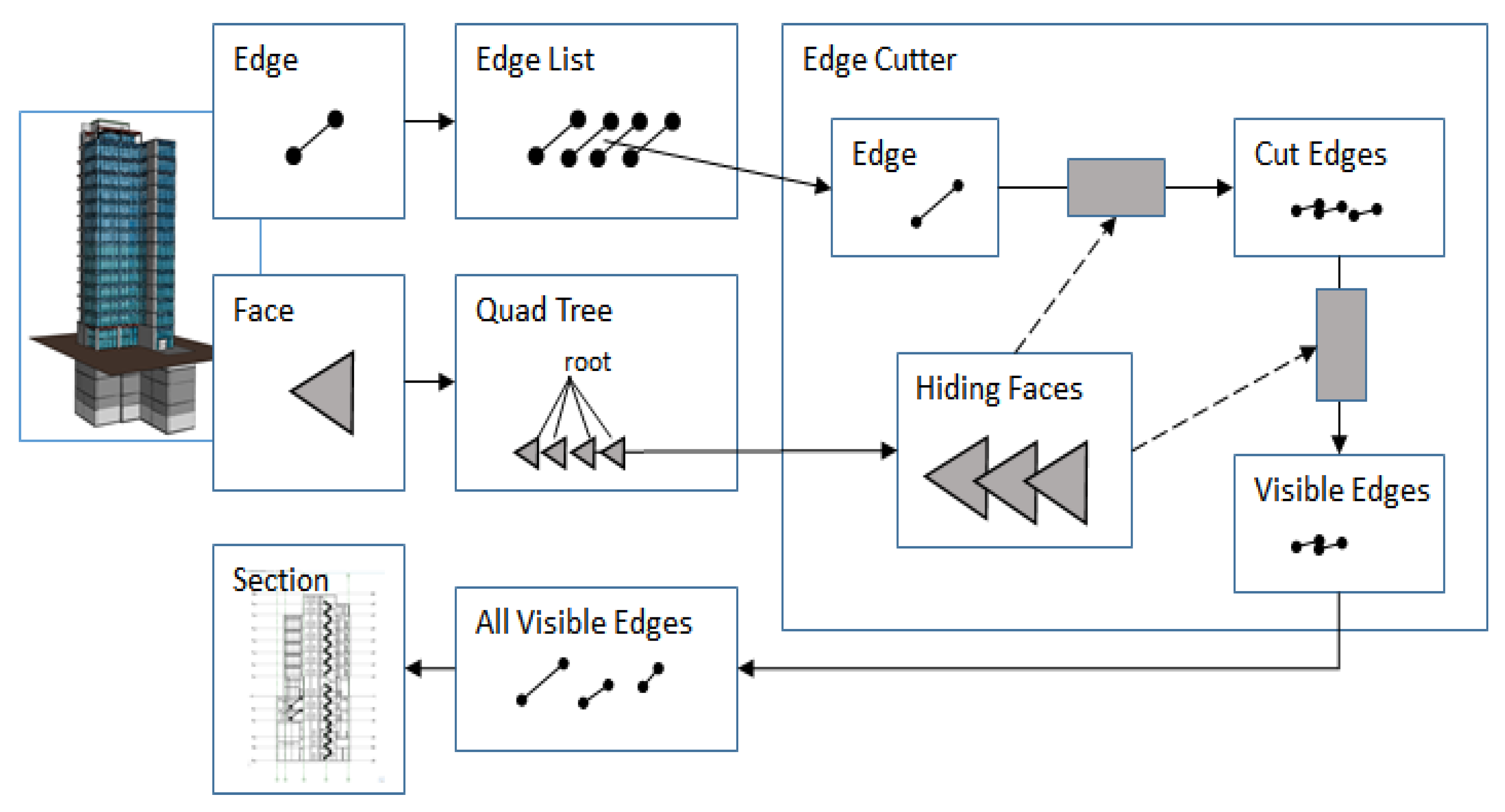
- Hidden line removal
- (i)
- Convert all lines and faces to the current screen coordinates (the horizontal axis of the screen is the X axis, the vertical axis is the Y axis, and the depth direction perpendicular to the surface is the Z axis).
- (ii)
- All elements (lines and triangles) entered on the screen are divided into quad trees.
- (iii)
- A quad tree and a line or face that spans multiple areas are split.
- (iv)
- The elements in the quad tree node are cut and hidden in the front element according to the distance from the screen.
4. Validation of Automatic 2D Drawing Generation Program
4.1. IFC Viewer and Information Specification Review
4.2. Reflection of BIM Design Book Optimization Criteria
4.3. Simplification of BIM-Based Permit Drawing
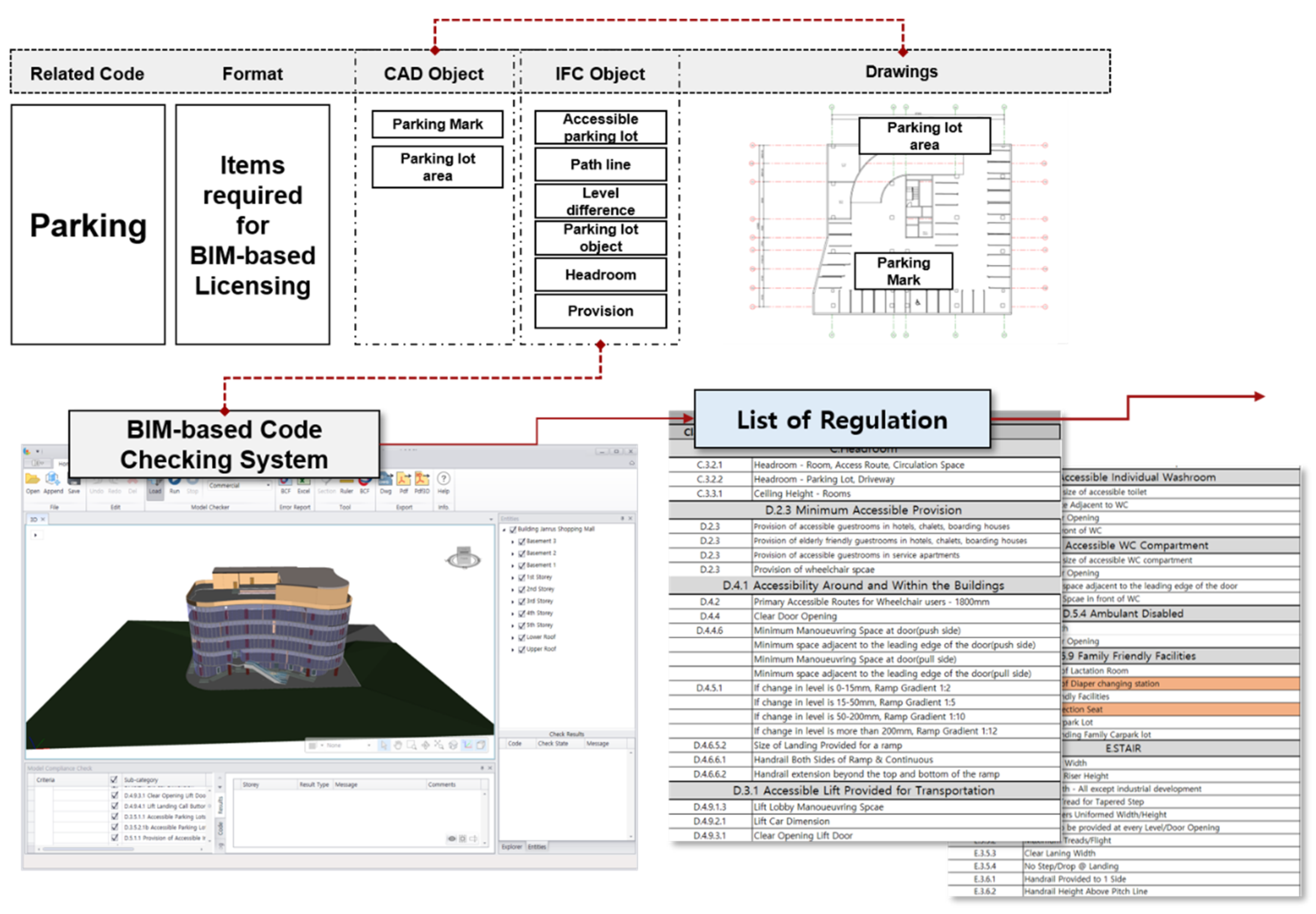
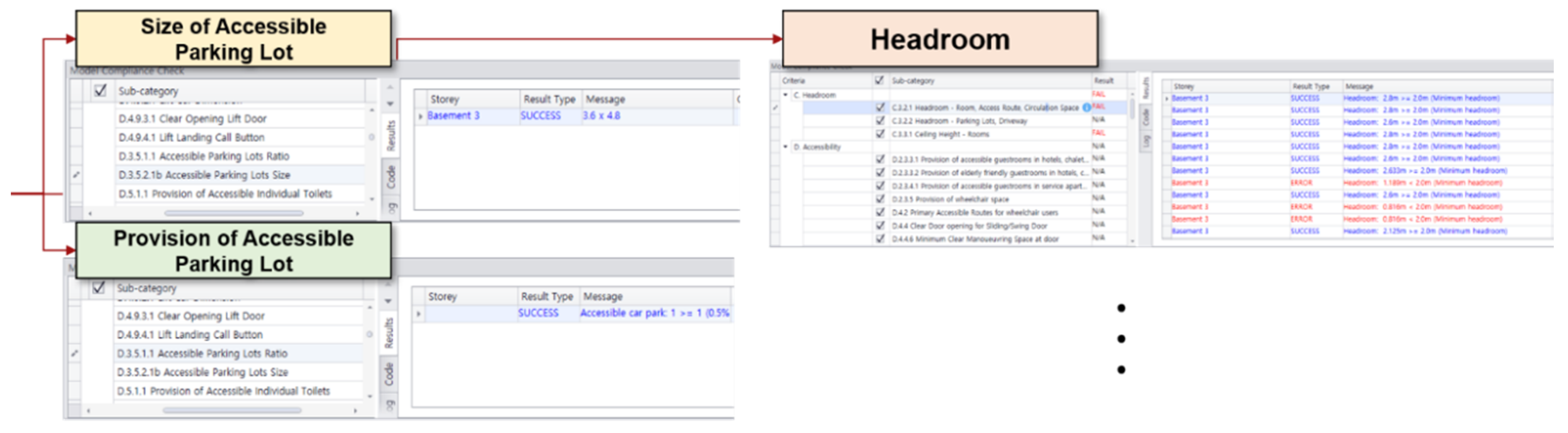
4.3.1. BIM-Based Permit Drawing Extraction
4.3.2. Review of BIM-Based Licensing Laws
5. Conclusions
Author Contributions
Funding
Conflicts of Interest
References
- Rad, A.R.; Banazadeh, M. Probabilistic risk-based performance evaluation of seismically base-isolated steel structures subjected to far-field earthquakes. Buildings 2018, 8, 128. [Google Scholar] [CrossRef] [Green Version]
- Kim, I.; Choi, J.; Kim, M. Improvement of open bim-based building permission process using epi (energy performance index). Korean J. Constr. Eng. Manag. 2015, 16, 124–135. [Google Scholar] [CrossRef]
- Choi, J. A Study on the Development of Code Checking System for Building Administration Process Applying Open BIM-Based Process. Master’s Thesis, Kyung Hee University, Yongin-si, Korea, 2014. [Google Scholar]
- BuildingSMART. Available online: http://www.buildingsmart.org (accessed on 28 May 2020).
- Choi, D.C.; Shin, H.M. A study on BIM-based information IFC4 standard format converter technology—Focused on analysis of problems in IFC 2X3 and the importance ofIFC4 standard format. Korea Sci. ART Forum 2015, 19, 669–677. [Google Scholar] [CrossRef]
- Kim, Y.; Kim, H.; Kim, M. Support plan for introduce of BIM on Small and Medium Architectural firm. J. Korea Acad. Ind. 2016, 17, 669–679. [Google Scholar]
- Lee, K.H.; Lee, G. 2018 Survey on the Status of BIM Adoption in Korea; BuildingSMARTKOREA: Seoul, Korea, 2019; Volume 20, pp. 8–12. [Google Scholar]
- Cho, Y.-S.; Lee, H. A study on the possibility of 2D design drawing implementation by revit architecture. J. Korea Acad. Coop. Soc. 2013, 14, 5243–5250. [Google Scholar] [CrossRef]
- Chae, K.; Lee, E.; Jun, H.; Lee, M.; Kim, K.; Choi, J.; Yoo, S. A Research on Drawing Representation for BIM (Building Information Modeling). In Proceedings of the Computational Structural Engineering Institute Conference, Seoul, Korea, 17 April 2008; pp. 470–475. [Google Scholar]
- Lee, B.; Kim, C. Design and implementation of the quantity surveying and shop drawing system for structures. In Proceedings of the Computational Structural Engineering Institute Conference, Seoul, Korea, 14 April 2011; pp. 132–135. [Google Scholar]
- Kim, Y.; Chin, S. An analysis of the problems of BIM-based drawings and implementation during the construction document phase. In Proceedings of the 36th International Symposium on Automation and Robotics in Construction (ISARC), Banff, AB, Canada, 21–24 May 2019; pp. 179–186. [Google Scholar]
- Nath, T.; Attarzadeh, M.; Tiong, R.L.; Chidambaram, C.; Yu, Z. Productivity improvement of precast shop drawings generation through BIM-based process re-engineering. Autom. Constr. 2015, 54, 54–68. [Google Scholar] [CrossRef]
- Nation Law Information Center. Enforcement Decree of the Building Act Attached Table. 2, Design Book Required for Building Permission Application (Related to Article 6 (1)). Available online: https://www.law.go.kr/ (accessed on 28 May 2020).
- Architectural Institute of Korea, BIM Guideline for Architectural Design Drawings; Architectural Institute of Korea: Seoul, Korea, 2016.
- Building Construction Authority, Singapore BIM Guide Version 2; Building Construction Authority: Singapore, 2013.
- Building Construction Authority. BuildSG Transformation Fund. 2020. Available online: https://www1.bca.gov.sg/buildsg/buildsg-transformation-fund (accessed on 27 May 2020).
- Statsbygg Building Information Modeling Manual—Version 1.2—English Version; Statsbygg: Oslo, Norway, 2011.
- Raja, R.A.; Svetlana, O. Building information modeling: Applications and practices. Am. Soc. Civ. Eng. 2015, 22–61. [Google Scholar] [CrossRef]
- General Services Administration, GSA BIM Guidelines for Revit: Data Submittal; General Services Administration: Washington, DC, USA, 2020. Available online: https://www.gsa.gov/ (accessed on 29 May 2020).
- Czmoch, I.; Pękala, A. Traditional design versus BIM based design. Procedia Eng. 2014, 91, 210–215. [Google Scholar] [CrossRef]
- Seo, H.-C.; Oh, J.-K.; Kim, J.-J. The analysis of job stress of workers in the architectural design firm after the introduction of BIM. Korean J. Constr. Eng. Manag. 2012, 13, 120–131. [Google Scholar] [CrossRef]
- Solibri Inc. Available online: https://www.solibri.com/how-it-works (accessed on 29 May 2020).
- Kim, J.C.A.I. A Methodology of Building Code Checking System for Building Permission based on openBIM. In Proceedings of the 34th International Symposium on Automation and Robotics in Construction (ISARC), Taipei, Taiwan, 28 June–1 July 2017; pp. 945–950. [Google Scholar]
- BuildingSMART Korea. Available online: http://kbims.or.kr/sub/Default.aspx (accessed on 29 May 2020).
- Jin, S.; Oh, M.; Kim, Y. BIM BIM Design Book Preparation Guideline (Implementation Design Stage) v.1.0; Korean Institute of Building Information Modeling: Seoul, Korea, 2019. [Google Scholar]
- Ahn, Y. Advance Standard Announcement (Research on Preparation of Strategy to Activate BIM to Strengthen Competitiveness in Future Construction Industry); Ministry of Land, Infrastructure and Transport: Sejong-si, Korea, 2020.
- Jo, C. Development of OpenBIM Platform for IT Integrated Architectural Design and Application Technology, KAIA. Available online: http://kaia.re.kr (accessed on 29 May 2020).
- BIMServices, 2-Stage Innovation Grant Stage 2 Automated Code Compliance Check in BIM (Final Report); BIMServices: Singapore, 2019.
- Moon, H.; Kim, B.; Ju, K. The Developing Strategy of BIM Library for Road Facilities based on Detailed Standard Drawing; Korea Institute of Construction Engineering and Management: Seoul, Korea, 2013; pp. 36–43. [Google Scholar]
- Oh, H.; Jung, J.; Lee, J. A guideline for structural drawings based on BIM. J. Archit. Inst. Korea Struct. Constr. 2013, 29, 39–46. [Google Scholar]


| No. | Information | Contents |
|---|---|---|
| 1 | Geometric information | Definition of the form of the model for each building object (e.g., IfcDoorLiningProtertie, IfcSweptSurface, IfcExtrudedAreaSolid, IfcAxix2Placement3D, etc.) |
| 2 | Building elements | Examples of building elements are walls, beams, and doors (e.g., Ifcslab, IfcColumn, IfcBeam, IfcWall, IfcBuildigElementProxy, etc.) |
| 3 | Structure elements | Elements used for structural analysis, such as nodes, lines, and loads (e.g., IfcReinforcingbar, IfcStructuralLoad, IfcStructuralMember, etc.) |
| 4 | Facility elements | Air-conditioning facility, drainage facilities, fire-extinguishing facilities, electricity (lamps, motors, heat, circuits, etc.), etc. (e.g., IfcBoiler, IfcAirTerminal, IfcChiller, IfcController, IfcLightFixture, etc.) |
| 5 | Construction management | Construction resource information related to construction equipment, materials, and workers (e.g., IfcActor, IfcOccupant, IfcMaterialUsageDefinition, etc.) |
| 6 | Maintenance | Information on equipment (e.g., IfcUnitaryEquipment, IfcValve, etc.) |
| 7 | Construction process | Construction process, procedures, activity, etc. (e.g., IfcProcedure, IfcEvent, IfcTask, etc.) |
| 8 | Estimate | Information on the budget of the project (e.g., IfcAsset, IfcCostItem, IfcCostSchedule, IfcCostValue, etc.) |
| 9 | Material properties | Information related to properties of materials (e.g., IfcMaterial, IfcMaterialLayer, IfcMaterialLayerSet, etc.) |
| 10 | Performers | Information related to workers such as man-hours, Work Breakdown Structure (WBS) etc. (e.g., IfcWorkCalender, IfcWorkSchedule, etc.) |
| 11 | Other | Time, constraint relationship, spatial objects, etc. (e.g., IfcSpatialElement, IfcZone, IfcConstraint, IfcRelSpaceBoundary, etc.) |
| Type of Document | Contents | Derivable Items |
|---|---|---|
| Architectural plan | Outline (location, site area, etc.) | |
| Regional District and City Planning Matters | ||
| Building scale | ||
| Parking area size (parking line, provision of parking lot, etc.) | √ | |
| Layout | Scale and bearing | |
| Length and width of the road facing the site | √ | |
| Longitudinal and horizontal view of the site | √ | |
| Distance from the building line and land boundary line to the building | ||
| Parking circulation and outdoor parking plan | √ | |
| Public open area and landscape plan | ||
| Floor plan | Floor plan of the first floor and standard floor | √ |
| Location of pillars, walls, windows, etc. | √ | |
| Location of fire protection zones and fire doors | √ | |
| Location of corridors and stairs | √ | |
| Location of elevator | √ | |
| Elevation | Elevation plan of 2 or more sides | √ |
| External finishing material | ||
| Plan for installation of signboards and building plates | √ | |
| Section | Longitudinal and horizontal sections | √ |
| Building height, height of each floor, and ceiling height | √ | |
| Structure | Main structural plane and section | √ |
| Detailed drawings of main structural parts | ||
| Structure confirmation | ||
| Interior finish | Types of wall and ceiling finishes |
© 2020 by the authors. Licensee MDPI, Basel, Switzerland. This article is an open access article distributed under the terms and conditions of the Creative Commons Attribution (CC BY) license (http://creativecommons.org/licenses/by/4.0/).
Share and Cite
Kim, I.; Lee, Y.; Han, C.-H.; Kim, G.; Choi, J. Validation of Support for Creation of License Drawings Using Application for openBIM-Based Automatic Generation of 2D Drawings. Appl. Sci. 2020, 10, 6470. https://0-doi-org.brum.beds.ac.uk/10.3390/app10186470
Kim I, Lee Y, Han C-H, Kim G, Choi J. Validation of Support for Creation of License Drawings Using Application for openBIM-Based Automatic Generation of 2D Drawings. Applied Sciences. 2020; 10(18):6470. https://0-doi-org.brum.beds.ac.uk/10.3390/app10186470
Chicago/Turabian StyleKim, Inhan, Yongha Lee, Choong-Hee Han, Gutaek Kim, and Jungsik Choi. 2020. "Validation of Support for Creation of License Drawings Using Application for openBIM-Based Automatic Generation of 2D Drawings" Applied Sciences 10, no. 18: 6470. https://0-doi-org.brum.beds.ac.uk/10.3390/app10186470