BIM-Based Spatial Augmented Reality (SAR) for Architectural Design Collaboration: A Proof of Concept


1
Department of Building and Real Estate, The Hong Kong Polytechnic University, Kowloon, Hong Kong
2
School of Natural and Built Environments, University of South Australia, Adelaide, SA 5000, Australia
3
Department of Civil and Environmental Engineering, Hanyang University, Seoul 04763, Korea
*
Author to whom correspondence should be addressed.
Appl. Sci. 2020, 10(17), 5915; https://0-doi-org.brum.beds.ac.uk/10.3390/app10175915
Submission received: 13 July 2020
/
Revised: 21 August 2020
/
Accepted: 21 August 2020
/
Published: 26 August 2020
(This article belongs to the Special Issue BIM and Its Integration with Emerging Technologies)
Abstract
:Three-dimensional (3D) visualization technology, such as augmented reality (AR), has served as the display for building information modeling (BIM)-based architectural design collaboration to provide more effective design observation and communication for stakeholders. That said, AR has several technical limitations in terms of personal device issues, user experience, and visualization quality. A new form of AR called spatial augmented reality (SAR) has been introduced to address these issues, which uses a digital projector to present graphics on physical objects for augmenting real-world objects. Therefore, SAR has great benefits and potentials to combine with BIM for design collaboration. This paper introduces a BIM-based SAR operational framework, where 3D building models generated from BIM software are imported to projection mapping tools to display building surface textures on physical white building models. A case study using Revit and 3ds Max as the BIM software, and MadMapper as the projection mapping tool, was conducted to demonstrate the feasibility of the proposed framework and to evaluate the projection performance of SAR. The case study showed that the texture of BIM models could be projected on the objects clearly and realistically. Additionally, the proposed SAR method potentially offers intuitive observation of building models and comfortable wear-free experience for collaborative design, and the qualitative analysis by changing the parameters was conducted to test the different projection conditions. Since it is expected that the use of SAR can be promoted by overcoming the discussed technical limitations and possible solution application, this study aims to traceability provide the whole process of BIM-based SAR for architectural design collaboration.
1. Introduction
For architectural design, effective design collaboration is vital, as it helps to promote teamwork through encouraging cooperation, as well as sharing stakeholders’ ideas and project knowledge [1]. Architects often work with not only peers but also professionals from other relevant backgrounds to address complex problems that are synthesized by multidisciplinary issues. Effective design collaboration can foster more creative design proposals, which might not be possible with the limited capability of architects [2]. Recently, the use of building information modeling (BIM) has facilitated close cooperation between different project stakeholders, including architects, engineers, contractors, and clients during the design phases of construction projects [3]. The technical core of BIM consists of 3D imagery and information management for buildings [4]. Since all the data is accessible in 3D, BIM could further promote the use of visualization as a method to exchange ideas and share knowledge within and amongst various stakeholders in a project, and some BIM viewer software are developed and available for users’ communication [5].
Despite the advantages of visualizing architectural concepts using 3D models, existing BIM visualization platforms are not effective for sufficient design information sharing [6]. In particular, even though 3D models could be built by BIM software, participants would still have to image and map the models that are on 2D display mediums into the 3D real space, which relies on the spatial awareness of the participants [7]. To address this issue, previous studies have attempted to promote the process of translating modeling data into more intuitive physical experience by mixing simulated models with an actual environment [7]. In this context, augmented reality (AR) has been introduced as an alternative visualization platform to effectively convey 3D models into realistic insights via an extended assistance of BIM visualization [4]. AR is generally used to enhance real-world objects and spaces by using digital information [8]. In AR, data that stimulates and enhances the real world is presented and integrated into the user’s observation [9], which shares resources between an AR display and users. These shared resources help to recognize relevant issues and inspire a new way of solution generation [10,11]. Due to these aspects, AR has also gained attention for design review and collaboration. AR is suitable for developing an interactive 3D communication environment for design, allowing users to explore the greater potential of design scenarios and the ability to evaluate 3D BIM models more intuitively before being physically built [12]. Incorporating AR and BIM promotes collaborative attributes and realistic 3D visualization. AR also works as an extension or a supplement of BIM to immerse abstract 3D images into the user’s view of the real world, which reaches a deeper level of reality [13].
Two types of AR display devices have been used for design collaboration: (1) hand-held devices such as tablets and mobile phones, and (2) head-mounted displays (HMDs) such as Microsoft HoloLens [14,15]. Generally, in collaborative AR systems, virtual models displayed to users by hand-held devices or HMDs are consistent, and users can communicate with each other with details displayed on the screen [16]. However, existing AR display devices have been criticized from the drawbacks of (1) technical limitations of real-time tracking caused by the detecting sensors, (2) users’ limited vision and uncomfortable wearing experience, and (3) unsatisfying visual quality of deviated perception and display issues due to screen display [17,18,19,20]. Recently, a new form of AR called spatial augmented reality (SAR) has been introduced to address these issues. SAR uses a digital projector to present graphics on physical objects to augment real-world objects and spaces, where display devices are separate to users, as opposed to the body-attached displays of AR [21]. Moreover, SAR does not require additional expensive AR devices, and it uses visual registration to avoid the inevitable error of sensor detection. The device is also separate from users, which therefore avoids potential discomfort, and provides ultimate stereo views since virtual objects are actually projected into reality. The truer view (without a screen display) could moderate false perception to a greater extent for users. Due to these aspects, SAR has a great potential to be used for architectural design collaboration.
In this regard, we propose a conceptual framework for BIM-based projection mapping using spatial augmented reality technologies for better architectural design collaboration through rapid prototyping of BIM-based 3D models. The literature review of BIM-based AR for architectural design collaboration and SAR for design collaboration is stated. Then the framework advises the whole BIM-based SAR procedures from the generation of 3D virtual and physical models, UV maps, and texture files to the image projection using projection mapping software as the SAR output method, with the correct geometric matching between virtual models and physical models. To test the feasibility of the proposed framework, we conducted a case study by using a projection mapping tool and varying projection conditions. Based on the case study, we discussed the potential and remaining research challenges, in addition to suggesting the future direction.
2. Literature Review
2.1. AR for BIM-Based Architectural Design Collaboration
Augmented reality (AR) is a mixed reality technology that enhances a user’s perception of the real world through information provided by computer systems, which superimposes computer-generated virtual objects, scenes, or system prompts on real scenes to achieve the “enhancement” of reality [22]. The widely accepted components of AR are 3D registration, the combination of virtuality and reality, and real-time interaction [14].
Previous research efforts have demonstrated the possibility of combing AR and BIM for architectural design collaboration. Fukuda et al. conducted an experiment using AR simulation with real-time video played on a laptop, where 3D models were superimposed in an on-site scene to foresee the conditions of the constructed buildings [23]. An auto AR system developed by Oppermann can visualize 3D BIM models on building sites in live videos using a head-mounted display and position-detection sensors to establish a real-time precise overlay of building models on a real site [24].
There are several advantages of applying AR technology in design collaboration. First, objects which do not exist in reality can be viewed and analyzed. Using an AR display, users can hold their individual views under their own control, and the displaced information can be adjusted in various forms [25]. For face-to-face design collaboration, AR could improve the information sharing of collaborative physical spaces, providing an interface for intuitive 3D interactive work assisted by computers. AR could also benefit remote collaboration. A study by Kato et al. found that AR offered substantially stronger co-presence and enhanced the immediate perception of communicative interactions [26].
However, despite the advantages of AR, several limitations have been also found. From a technical perspective, existing AR systems that use a tablet or head-mounted display require real-time tracking technology that relies on sensor detection to enable precise and effective registration while users are in motion. Within this framework, sensor errors may easily occur [18]. Furthermore, users may feel discomfort caused by holding a tablet or wearing a heavy head-mounted device [20]. As existing AR users see an augmented view through their own AR displays, it is difficult to build common reference points between users when representing spatially-located virtual data, which as a result, hinders the common understanding of virtual information compared with a shared physical space [19,27]. The quality of visualized information is still low due to the technical limitations of existing AR devices. For example, while using a head-mounted AR display (e.g., Microsoft HoloLens), low resolution, distortion, and limited field of view could lead to a false perception of visualized information. Brightness, contrast, and visibility are other screen-related issues that can significantly affect visualization quality [17].
2.2. SAR for Design Collaboration
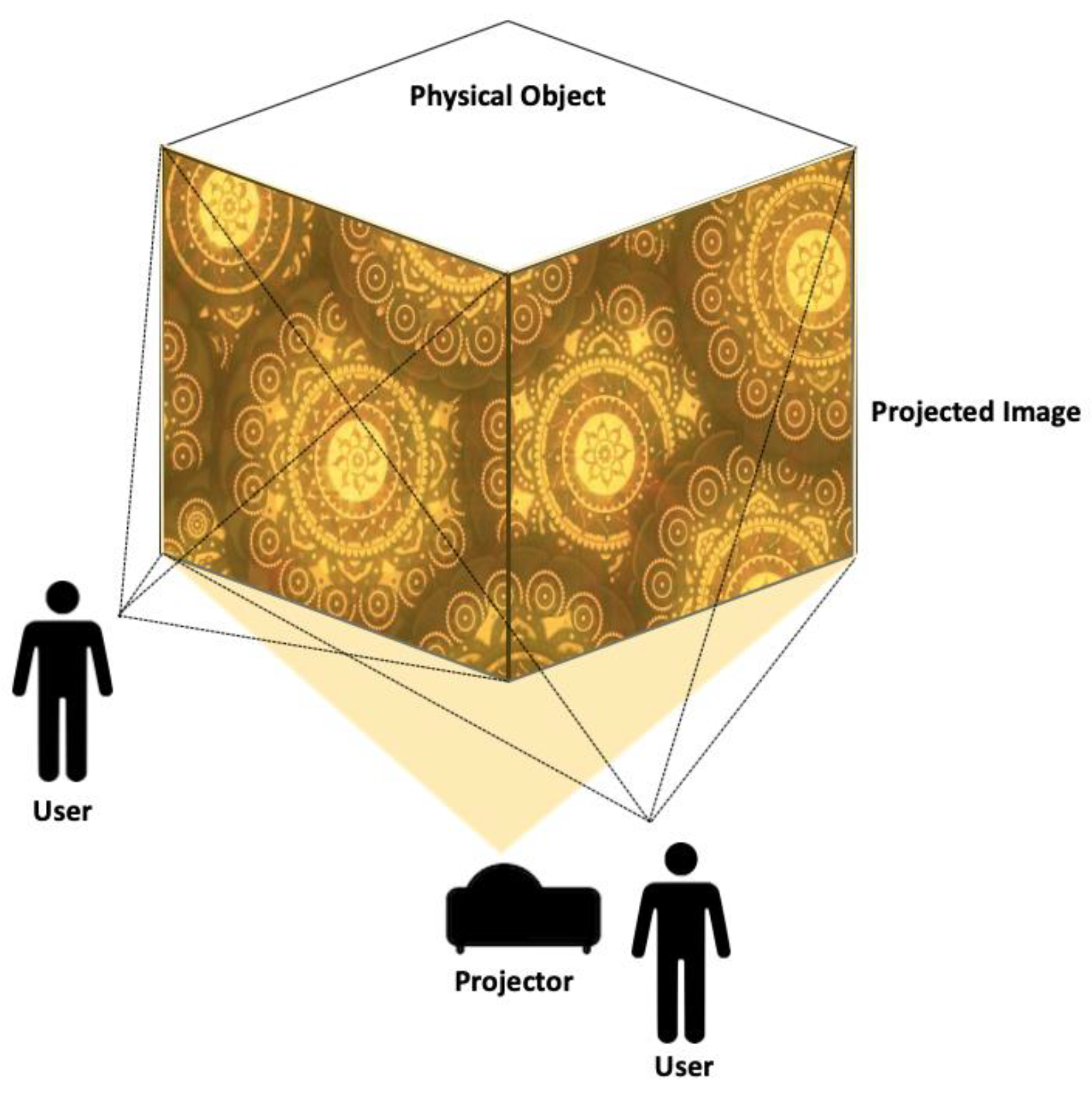
Spatial augmented reality (SAR) provides the experience of augmented reality by changing the appearance of the physical world with an optical projector (Figure 1). Compared to AR technology, SAR separates the display technology from a user’s body and embeds it into a physical model [21,28,29]. For SAR, the real world is augmented by a display that is integrated directly into the user’s physical environment—not merely through the user’s field of vision—to maximize the user’s level of immersion [30,31]. The images may appear in 2D, placed on a flat display surface, or may be 3D and float over a planar surface, or even 3D and float over an uneven surface. Seeing a design in a projection-based mixed reality environment helps users to better understand how a virtual product actually looks like in the real word. Moreover, not only will users obtain an augmented display of various prototypes themselves, but they can also interact with their customers in a creative and improved manner [32]. It is also worth mentioning that when SAR is applied to moving objects, the position of those objects is required in real time to facilitate dynamic mapping [33].
The designed displays of SAR have been applied to various domains to explore how SAR systems can be applied to enhanced design mock-ups. In particular, there have been applications in the automotive industry, which uses virtual content to design and assess new components for cars [34]. For instance, virtual content may be projected on a mass car model to help during a collaborative design session. Similar to the automotive industry, architectural design uses 3D building models to benefit from SAR technology for design collaboration. Verlinden et al. created a SAR system that combined the rapid prototyping of a physical model and an illuminating touchable interface for the aesthetic design of an automobile. The physical mass model of automobile was placed on a turntable to offer rotational movement, and the tangible interface was projected on a vertical planar screen [35]. Porter et al. applied the SAR system when designing an automotive dashboard. The dashboard’s designs were fully projected on a mock-up model, and the texture could be changed to reflect particular design decisions. By changing the projection with the displays of several designs, users were able to compare and evaluate snapshots of possible layouts, even though the mapping did not have high fidelity [36]. Von Itzstein et al. also demonstrated the application of SAR when designing appliances for an oven, where the design alternatives were projected quickly and easily on a real-scale oven. This application demonstrated that using SAR allows non-technical stakeholders to effectively take part in a collaboration process of a product’s design [37]. With the potential of SAR becoming a new visualization platform, collaborative design in the building industry would likely benefit from this technology as well, with the combined usage of the 3D BIM model. Since this integrated application of SAR and BIM for design collaboration has not been tested so far, we have proposed a framework of BIM-based SAR for a detailed individual building design collaboration.
3. Framework
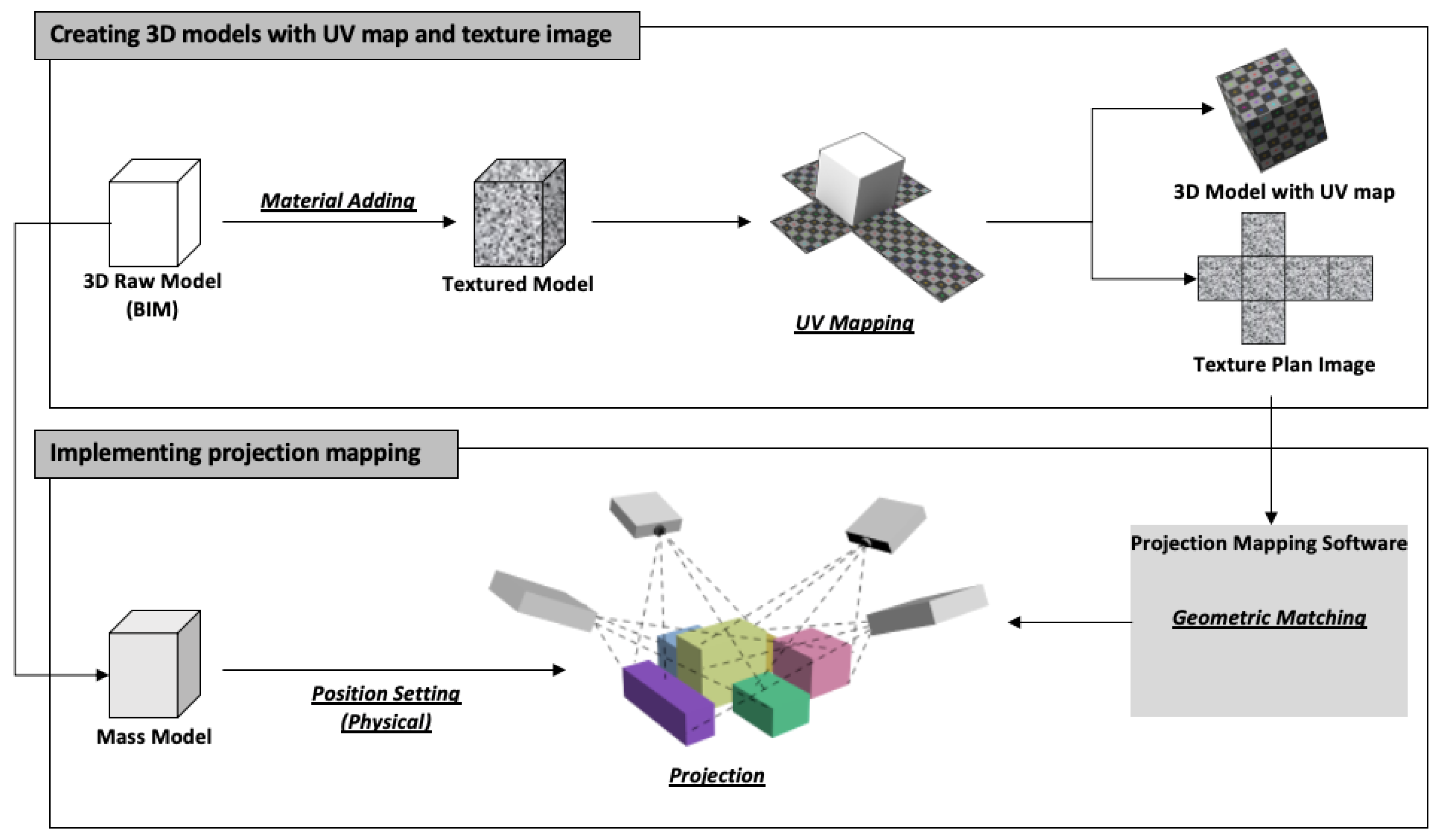
The proposed framework of BIM-based SAR for building design prototyping consists of two main parts (see Figure 2). The first process is creating virtual and physical 3D models, UV maps, and texture files. The next process is projection mapping implementation, which transforms videos or images into interactive displays on a target surface.
3.1. Creating 3D Models with UV Map and Texture Image
The first step is to build raw 3D models without texture through BIM software. Even though there might be original material information when creating a 3D building model in BIM software, the material information in the BIM is only for the information delivery to indicate the variety of designed material, rather than actually including the colored texture to the model surface. To create a 3D model whose surface material could be projected on a real object by a video projector [38], a material adding, or texture mapping procedure is required, either in the BIM software or 3D animation and rendering software. For example, the process of applying material to the object’s surface could be further done in the same BIM software such as Revit, after completing the raw 3D building model [39]. Meanwhile, to create physical mass models as the base of projection, white-colored physical mass models are made in proportion to the 3D building model.
The next step is to create UV maps and texture image files. UV mapping is the process of translating a 3D surface with volume and shape onto a flat 2D image, where the 2D image is referred to as a UV map [40]. The U and V refer to the horizontal and vertical axes of the 2D space, as X, Y and Z are already used in 3D space. During the UV mapping process, a polygon mesh needs to be produced, which is the collection of vertices, edges, and faces that make up a 3D object. After producing the polygon mesh, the seams on which the unwarping is based will be clearly defined. This step is normally automatically processed by UV mapping software. A UV map can be either have material texture, which can be used straight as the texture file, or without material texture, in which the texture file should be drawn based on the defined edge curves in the UV map. Furthermore, the UV map can be added to the raw 3D model, which is stored in the same file with the 3D model and can also be exported as an image file.
Depending on the software chosen, there might be a few ways to produce a UV map with the corresponding texture file of a 3D model. In this context, the software could have integrated functions of UV mapping, material adding, and 2D painting. There is existing software that offers professional and convenient material adding for building design, and the entire complicated building texture is not easy to be drawn in a UV map. Therefore, as shown in Figure 2, the way we suggest is to add the material to 3D models to change the surface appearance before the UV mapping process, to add color, detail, and texture to the 3D objects created in the 3D modeling software. Therefore, both the UV map and texture file would be generated by UV mapping a material-added 3D model. Commercial software, such as Autodesk 3ds Max and Blender provide both functions of material adding and UV mapping. The texture baking function might also be provided in this software to generate the texture file of a 3D object whose material is added by the other software such as Unity [38,39]. In addition, a supplemental method could be used if the textured model is not fully prepared or there are slight changes on the designed texture. Since a 3D model is clearly unfolded at the seams and laid out flat on a 2D plan, once the UV mapping is complete, users can produce a custom image on the “pattern” of a UV map through 2D painting. This is similar to filling the color chunk on the UV map, which is linked to the respective area of the building model. This process makes it possible to produce models that are rich in color and detail with graphics software such as Photoshop. It is worth mentioning that Blender could also perform texture painting on the UV map and textures are displayed on the 3D object in the meantime. [41,42].
3.2. Implement Projection Mapping
Appropriate hardware and software are required to implement projection mapping. There are several types of commercial software with projection mapping that is compatible with 3D models with UV maps and texture images. Users should choose an appropriate software according to their computer configurations, such as operating system (Windows/Mac/Linux), processor (CPU), graphics card, etc. The throw ratio of projectors should also be evaluated in advance—according to the prospective magnitude of mass models and the size of the experimental space—to have a proper image size under certain ranges of throw distance.
The proper position and connection of the equipment should be ensured for accurate projection mapping. The projector and the physical model must be placed where the projector throw can perfectly cover the target physical model. Additionally, a clear connection between equipment should be prepared to provide high display quality; a VGA port or HDMI port are generally utilized.
Geometric matching is the most essential process to accomplish projection mapping. This step includes building a geometric correspondence between virtual images and real objects to relate the points in the coordinate system of the images to the real-world coordinate system. In a nutshell, the elements of angles and size of projected virtual images should be matched to be projected at the right designed position on the real mass model. Finally, the accurate projection of the model image can be presented on the physical model based on the results of geometric matching.
4. Case Study
4.1. Case Procedures of BIM-Based SAR
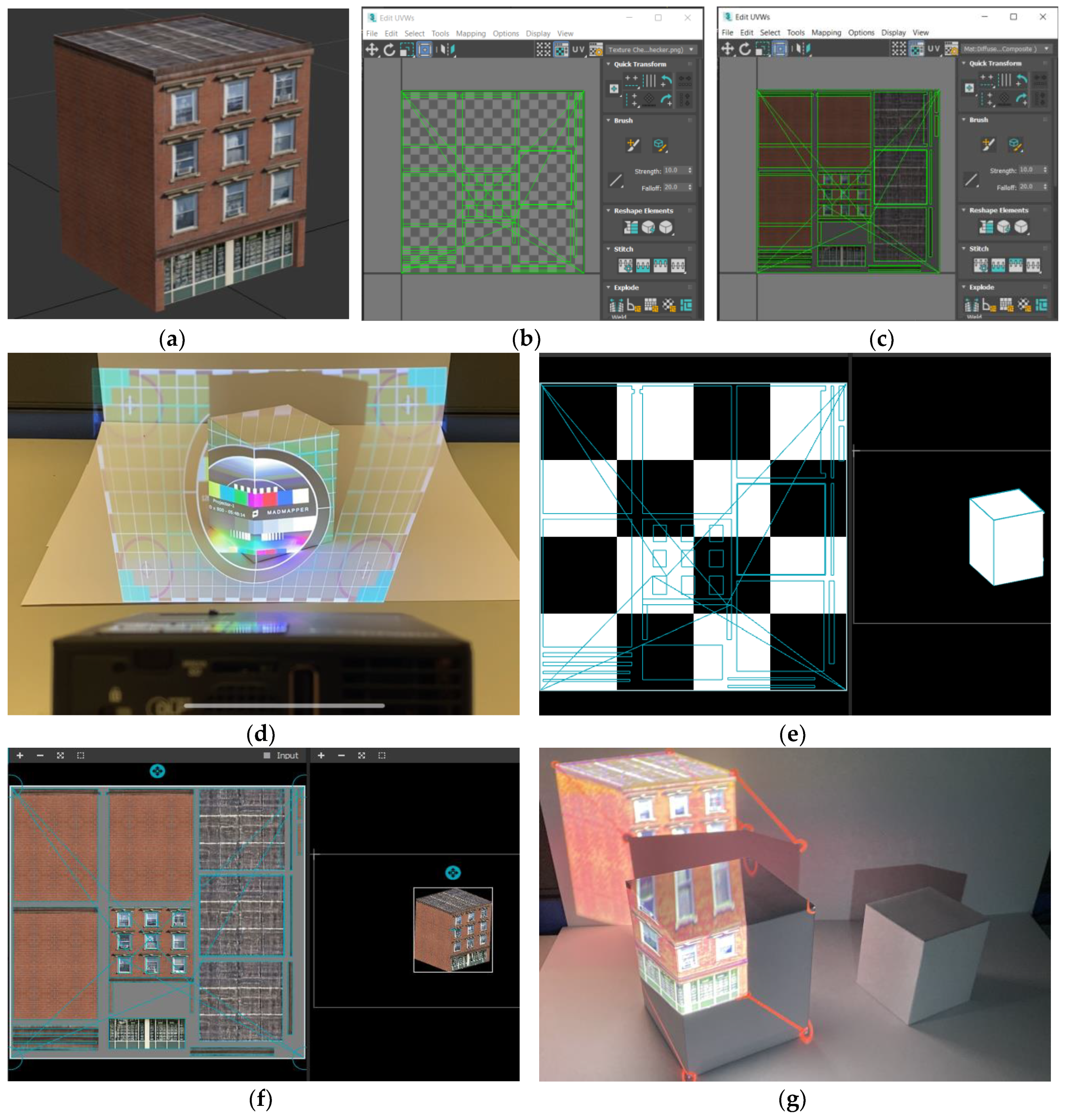
The first step was to create a 3D building model, UV map, and texture file. The 3D raw model of a four-story building was built in Autodesk Revit and exported as a FBX file format, which is compatible with Autodesk 3ds Max. The material information was added to the raw building models in Autodesk 3ds Max. The UV maps and texture plans were also generated in this software, as shown in Figure 3a–c. The UV maps could be added to different 3D model file formats, compatible with the projection mapping tools; and the texture plans were exported as image files.
Then, two-size mass models were made as the same proportional size as the virtual building model, where the proportion of dimensions are 78:79:100. The mass models were made of thick white cardboard, and the size of the two mass models are 8.3 × 8.4 × 10.1 cm, and 5.8 × 5.85 × 7.4 cm, respectively. The MadMapper was selected as the projection mapping software. The projector selected was Optoma ML550 with a throw ratio of 1.5/1 (D:W), which is suitable for the mass model size. This case study was conducted with the PC of Intel(R) Core (TM) i5-8250U CPU, 8 GB installed RAM, 256 GB SSD, Intel(R) UHD Graphics, and Windows 10 (64bits). The connection port used between PC and projector was HDMI.
The next step was to set up the position of the projector and the mass models. The “Show Test Pattern” function in MadMapper ensures the model is fully covered under the projection area, as illustrated in Figure 3d. Then, the virtual raw model file attached with the UV map and texture file was imported. The results displayed on the input channel in MadMapper is shown in Figure 3e,f. The file format of the 3D model should be an OBJ file due to the compatibility requirements of MadMapper. In MadMapper, virtual textured models can be moved, zoomed in or out, and rotated in the control panel.
The last step was geometric matching and projection. Geometric matching was proceeded by using the calibration function of MadMapper. It offers a manual calibration method that matches six points in the virtual model on the control panel of MadMapper with the correspondent six points on the physical mass model. As a result, the six points in both the virtual model and physical model can be marked and connected through a red line emitted from the projector (see Figure 3g). After matching the six reference points, the projected model image was automatically dragged to the expected position on the mass model, with the virtual model being dragged to the pointed position in the software panel. Moreover, micro adjustments could be further performed manually at the matching point for trimming the image to fit the object edge perfectly, so that the projection could be achieved.
As can be seen in Section 4.2, the realness level of the projected model and the similarity to the designed virtual model were satisfied. Although the imaging throwing technology of the projector is one of the core factors that would affect projection quality, the medium-class professional projector we selected for this case study was good enough overall to present the 3D model clearly and vividly. (Due to the working mechanism of the digital light processing (DLP) projector, there will be banding or line flicker when shooting the projection. Therefore, the captured results have nonnegligible anamorphosis from the actual scene observed by the eyes, and the performance is better for in situ observation).
4.2. Control Group Design and Results
To investigate the influence of the individual element on the performance of projection mapping, several elements in the proposed framework were tested for qualitative analysis. The selected control elements are mass model size, illumination condition, projection angles, and planar/curve projection surface. The explanation of setting and projection results are presented as follows.
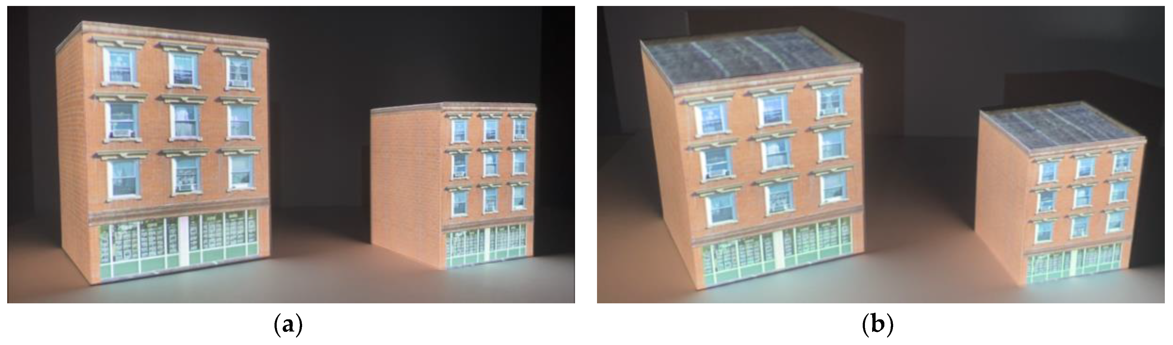
4.2.1. Mass Model Size
As described in Section 4.1, two types of model size were made; the augmented results are shown in Figure 4. The bigger model displays more clearly where there is dense detailed texture, such as the contents behind the window, glass door area, window frame texture, and sill. During the projection calibration process, the six reference points of the bigger model could be more precisely matched, which led to higher calibration accuracy. In addition, since the micro adjustment of one reference point would also slightly change the monolithic angle and distortion of the projected model in order to be consistent with the original geometric shape of the design model, there was less change and distortion in the bigger model and it was easier to operate.
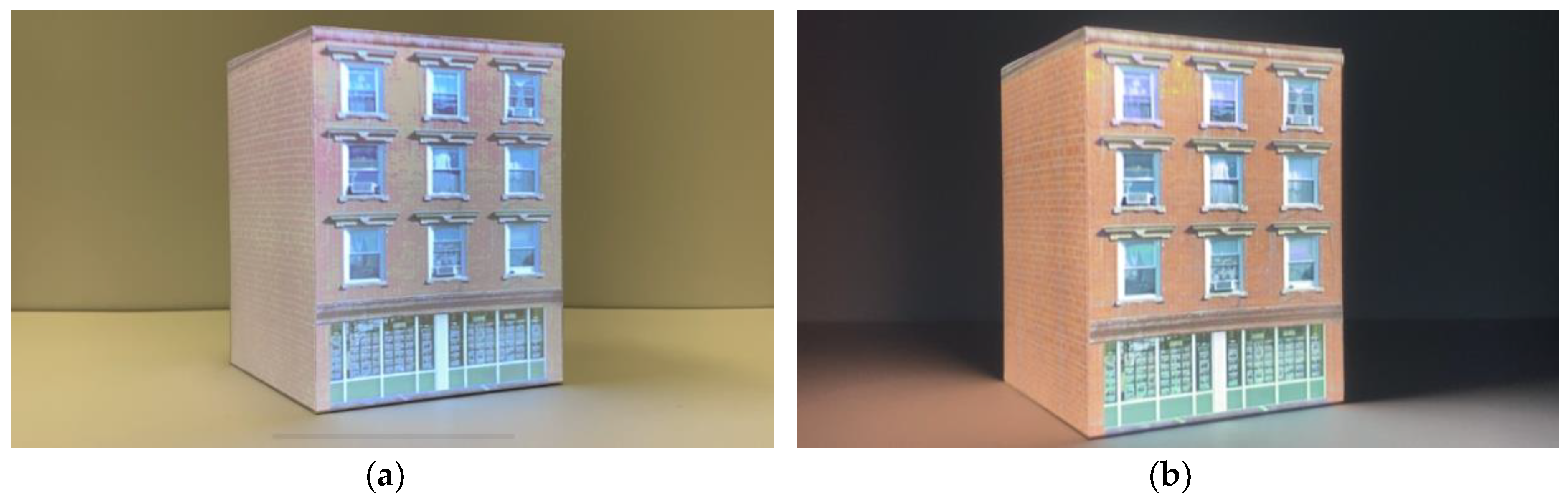
4.2.2. Illumination Condition
Two types of illumination conditions were simulated: with background light and without background light (see Figure 5). The biggest influence of lighting conditions on the projected image was color. The virtual image appeared to be closest to the original color scheme when the projection did not have background lighting. There was a higher degree of color contrast in the darker environment (no background lighting), especially on the lines and ridges of the model, such as the brick seams and window frame edges, which gave the projected model more depth and a stereoscopic effect.
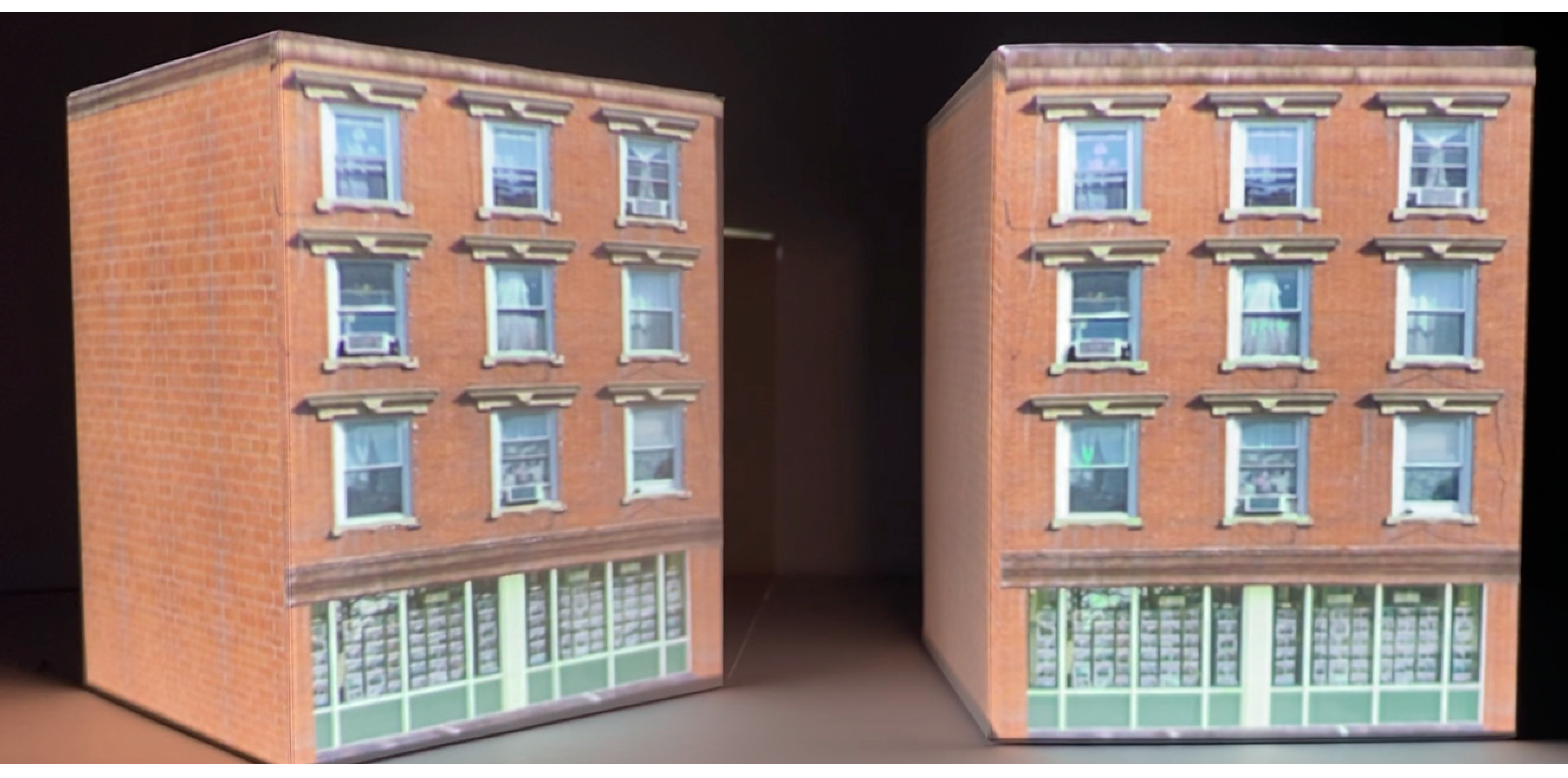
4.2.3. Projection Angles
The relative angle between the mass models and the projector were changed by rotating the models horizontally (see Figure 6). This session illustrates the influence of tangential distortion (keystoning) when the projected object has an angled surface. The projector was placed to throw the images more parallel to the front wall of the building model in a horizontal direction (as shown in the right side of Figure 6). When the building model was rotated horizontally to a certain angle (as presented in the left side of Figure 6), differences in projection could be detected. From the displays on the frontal wall of the building, the details seemed blurrier after rotation. Moreover, the relatively big difference caused by tangential distortion could be found in the flank wall, where the texture of the wall was projected much more clearly on the left-hand side in the figure.
4.2.4. Planar/Curve Projection Surface
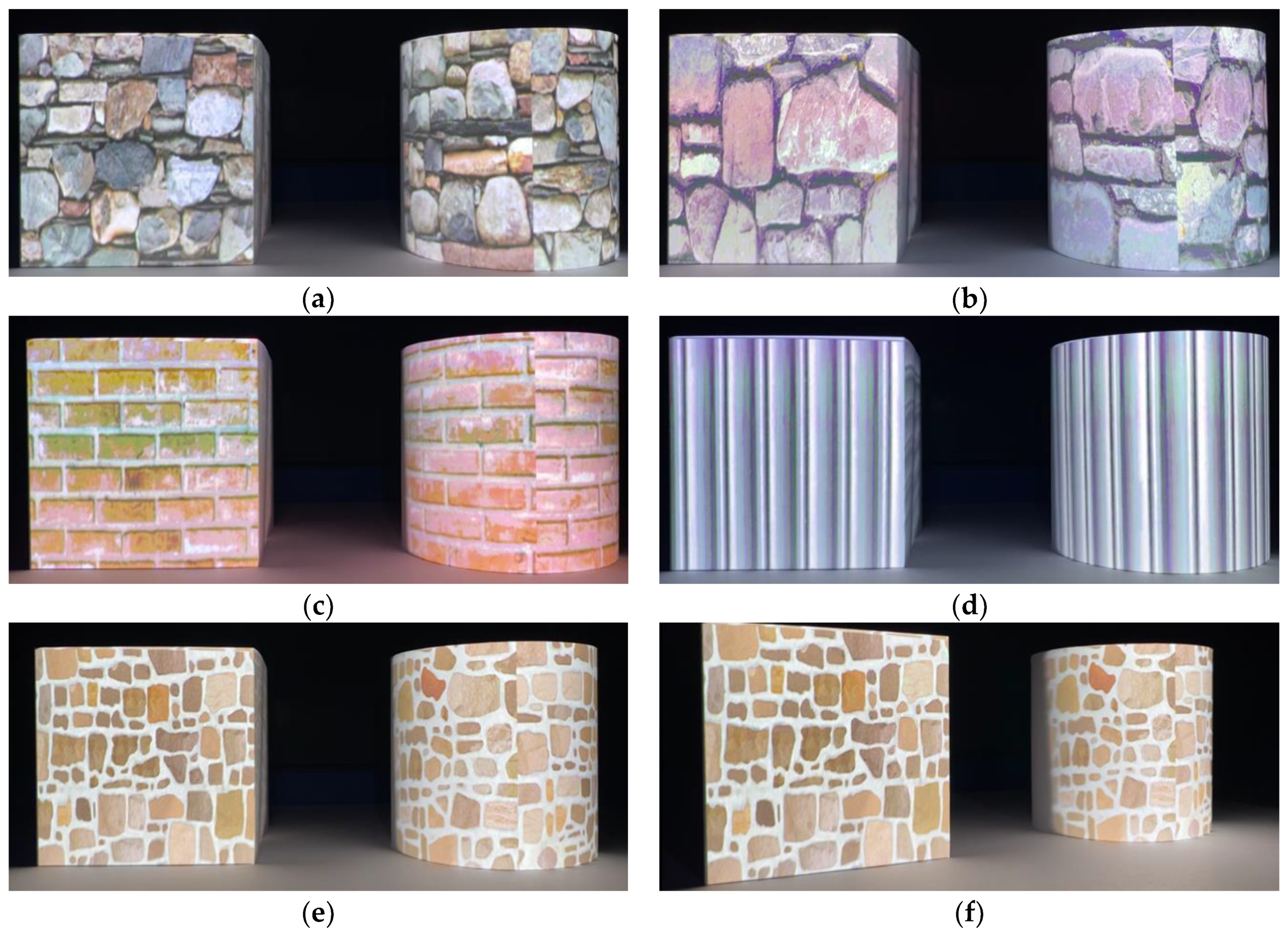
The planar and curve projection surfaces were tested in order to be compared. The tested models were made as a cylinder type and cube type by applying several textures of building materials on it (Figure 7). The typical building textures, such as brick, stone, and column pattern were projected on both planar and curved surfaces. On the curved surface, there was a distortion issue, which affected the level of texture definition and slightly changed the design. Furthermore, there were discontinuous areas of the texture on the curved surface, but this was caused by the discontinuous part of the cylinder flank on the UV map. Likewise, the curved surface wrapping around the object might need to be separately placed on the UV map, which will lead to the discontinuity in texture. Moreover, on the transitional area of the curved surface that cannot be projected on (Figure 7f), there was huge distortion, and the pixel quality deteriorated extremely close to the edge lines.
5. Discussion
We tested the feasibility of the proposed two-process framework by incorporating a projection mapping tool (i.e., the SAR rapid prototyping method) with a BIM model. Traditional AR relies on the sensor detection of the HMDs or hand-held devices for 3D position registration between the devices and the real world, leading to deviation results from sensor errors during operation. However, with the BIM-integrated SAR approach proposed in this study, 3D position registration is achieved through reference point assignment between the virtual and physical models in the real world. Once registration is complete, the corresponding 3D coordinate information provides a stable and accurate projection output, without the need for a wearable device or a continuous signal transmission from the sensors.
The use of this method for design review would have great potential to provide a more interactive and intuitive means for design visualization. During the design review process, there could be several scenarios of the building design to be displayed, such as different materials of the building, positions of building components (e.g., windows), and overall structural designs. These design alternatives can be quickly projected on a physical mass model of a building, supporting collaborative design between project participants. For example, textured models of varying design alternatives can be generated and visualized one by one using a projector during collaboration, allowing more interactive design comparison. If needed, users are able to make a change on building design using a BIM software, which can be simply and quickly inserted to the projection mapping software, and thus the updated design alternatives can be shown promptly on the physical model. For this process, only the presenter needs to operate the equipment, and the users do not have to hold or wear any devices during design collaboration activities. As a result, non-technical users can easily and intuitively review building models without feeling the discomfort or dizziness of wearing an AR device. Users can even move around to view models from different angles, similar to how a real building would be observed. According to the results of qualitative analysis in the case study, high-quality details from various perspectives were able to be easily observed, such as areas with a lot of visual contents and the building model edges. Through the proposed methodology, project participants could also share a common reference point in the projected SAR environment. This could be potentially beneficial for effective model-based collaboration between participants, since it would enable them to communicate face-to-face with a shared view of the model.
There are, however, some challenges remain when using the projection mapping tool for design collaboration. First, manual matching with at least six reference points (the basis of a stereo object) is only suitable for simple models, such as a cube. Certain building models may have a very complicated structure that contains many interleaved edges and a variety of small components of various shapes. In such cases, with more reference points being required for better matching, manual calibration would not be suitable, and a number of the components might not perfectly match due to their complex structures. Second, for projects with numerous design alternatives, especially with replaced physical models, or where the design is frequently changed, manual calibration might also be inappropriate since recalibration of the reference points would be required. Third, when constructing a 360-degree view of a building model, edge blending might occur if there are overlapping areas from multiple projectors. Finally, tangential distortion (keystoning) caused by projectors being non-perpendicularly aligned to the object surface, as well as projection distortion on non-planar surfaces, needs to be overcome.
To solve the aforementioned problems, a projector–camera system is suggested. Here, cameras are used as a proxy for the viewer to calculate the geometric correspondence between points in the projected images and the captured images of the object by the cameras, allowing the projected images to be aligned with the objects [43]. Geometric correspondence is generated by the calibration process of this system, while the calibration is self-forwarded [44]. Calibration methods such as those based on a checkerboard [45] and structured light have demonstrated the potential and speed of self-calibrated projector–camera systems to provide geometric information and deal with registration issues, allowing them to accurately match the projected image with the object. Using such a system would avoid unnecessary manual calibration and achieve faster dynamic projection of design changes. By pre-wrapping the images in terms of the object information derived from camera scanning, automatic calibration of a projector–camera system could also handle keystoning, blending issues as a result of using multiple projectors, and projection on 3D surfaces of complex shapes [44,46,47,48]. Research into automatic calibration for projection mapping has been focused and evolved. However, the tools for automatic calibration are still being developed [49], especially in terms of integrating different functions such as colorimetric correction, edging blending, and accusation of geometric information. At the same time, design software tools specific to the building industry also need to be developed.
In addition to the stated future studies, additional technical components need to be added in the proposed method for more interactive SAR building designs that would allow users to interact with augmented information, such as controlling the projected contents by gestures or other interactive mediums. For this functionality, a camera–projector system that enables tracking of a physical model and gesture recognition as an interactive medium could also be applied [50,51,52]. Also, considering that the range and amount of information in the BIM model increases as design progress, the proposed method needs to be extended to incorporate diverse building information from BIM models. For example, projecting information provided by various project participants, such as the HVAC information (heating, ventilation, and air conditioning) and structural details inside the building may need to be included in the proposed SAR-based design review framework. This will allow the simulation of building components and functions by using physical mass models, expanding the applicability of the proposed method not only for design phases, but also construction phases to check constructability.
6. Conclusions
Up until now, BIM-based AR design collaboration has been a popular means of presenting design solutions. However, AR technology does have some limitations, such as technical issues, negative user experiences, and quality of visualized information. SAR technology could potentially solve these problems. Through a BIM-based SAR framework, this study presents the implementation procedures and technical requirements necessary to generate 3D models and display surface textures on physical building models.
We also implemented and tested the feasibility of the proposed framework using a projection mapping tool to project virtual building models on cube-shaped objects. The result was a stable display of building models through projection mapping; thereby, demonstrating the potential to solve the current limitations of AR-based design collaboration activities. The results of the control elements setting show the better definition of bigger model size, projection distortion issues on curved and angled surfaces, and a clearer stereo projection view in darker environments. Nevertheless, issues still remain: manual calibration is unsuitable for complicated building models, displays of various design solution or dynamic projection mapping, and blending problems when applying several projectors. To resolve the aforementioned technical issues, a projector camera system and automatic calibration is suggested. Not only would this solve the technical limitations, it would also provide more interactive and intelligent SAR applications for interdisciplinary collaboration in the building industry.
Author Contributions
Conceptualization, J.S., S.A. and S.H.; methodology, Y.J. and J.S.; software, Y.J.; writing—original draft preparation, Y.J.; writing—review and editing, J.G.L. and J.S.; and project administration, J.S. All authors have read and agreed to the published version of the manuscript.
Funding
This research study was supported by the Early Career Scheme (PolyU 25210917) from Research Grants Council, Hong Kong, and the National Research Foundation of Korea (NRF) grant funded by the Korea government (MSIT) (No. NRF-2018R1A5A1025137).
Conflicts of Interest
The authors declare no conflict of interest.
References
- Gross, M.D.; Do, E.Y.-L.; McCall, R.J.; Citrin, W.V.; Hamill, P.; Warmack, A.; Kuczun, K.S. Collaboration and coordination in architectural design: Approaches to computer mediated team work. Autom. Constr. 1998, 7, 465–473. [Google Scholar] [CrossRef]
- Kalay, Y.E. Architecture’s New Media: Principles, Theories, and Methods of Computer-Aided Design; MIT Press: Cambridge, MA, USA, 2004. [Google Scholar]
- El-Diraby, T.; Krijnen, T.; Papagelis, M. BIM-based collaborative design and socio-technical analytics of green buildings. Autom. Constr. 2017, 82, 59–74. [Google Scholar] [CrossRef]
- Wang, X.; Truijens, M.; Hou, L.; Wang, Y.; Zhou, Y. Integrating Augmented Reality with Building Information Modeling: Onsite construction process controlling for liquefied natural gas industry. Autom. Constr. 2014, 40, 96–105. [Google Scholar] [CrossRef]
- Johansson, M.; Roupé, M.; Bosch-Sijtsema, P. Real-time visualization of building information models (BIM). Autom. Constr. 2015, 54, 69–82. [Google Scholar] [CrossRef]
- Oh, M.; Lee, J.; Hong, S.W.; Jeong, Y. Integrated system for BIM-based collaborative design. Autom. Constr. 2015, 58, 196–206. [Google Scholar] [CrossRef]
- Meža, S.; Turk, Ž.; Dolenc, M. Component based engineering of a mobile BIM-based augmented reality system. Autom. Constr. 2014, 42, 1–12. [Google Scholar] [CrossRef]
- Berryman, D.R. Augmented reality: A review. Med. Ref. Serv. Q. 2012, 31, 212–218. [Google Scholar] [CrossRef]
- Ahlers, K.H.; Kramer, A.; Breen, D.E.; Chevalier, P.Y.; Crampton, C.; Rose, E.; Tuceryan, M.; Whitaker, R.T.; Greer, D. Distributed augmented reality for collaborative design applications. In Proceedings of the Computer Graphics Forum, Orlando, FL, USA, 24–28 March 2002; pp. 3–14. [Google Scholar]
- Basadur, M.; Pringle, P.; Speranzini, G.; Bacot, M. Collaborative problem solving through creativity in problem definition: Expanding the pie. Creat. Innov. Manag. 2000, 9, 54–76. [Google Scholar] [CrossRef]
- Hong, S.W.; Jeong, Y.; Kalay, Y.E.; Jung, S.; Lee, J. Enablers and barriers of the multi-user virtual environment for exploratory creativity in architectural design collaboration. CoDesign 2016, 12, 151–170. [Google Scholar] [CrossRef]
- Ko, C.-H.; Chang, T.-C. Evaluation and student perception of augmented reality based design collaboration. Management 2011, 6, 6. [Google Scholar]
- Calderon-Hernandez, C.; Brioso, X. Lean, BIM and Augmented Reality Applied in the Design and Construction Phase: A Literature Review. Int. J. Innov. Manag. Technol. 2018, 9, 60–63. [Google Scholar] [CrossRef]
- Azuma, R.; Baillot, Y.; Behringer, R.; Feiner, S.; Julier, S.; MacIntyre, B. Recent advances in augmented reality. IEEE Comput. Graph. Appl. 2001, 21, 34–47. [Google Scholar] [CrossRef] [Green Version]
- Chen, H.; Lee, A.S.; Swift, M.; Tang, J.C. 3D collaboration method over HoloLens™ and Skype™ end points. In Proceedings of the 3rd International Workshop on Immersive Media Experiences, New York, NY, USA, 26 October 2015; pp. 27–30. [Google Scholar]
- Nee, A.Y.; Ong, S.; Chryssolouris, G.; Mourtzis, D. Augmented reality applications in design and manufacturing. Cirp Ann. 2012, 61, 657–679. [Google Scholar] [CrossRef]
- Kruijff, E.; Swan, J.E.; Feiner, S. Perceptual issues in augmented reality revisited. In Proceedings of the 2010 IEEE International Symposium on Mixed and Augmented Reality, Seoul, Korea, 13–16 October 2010; pp. 3–12. [Google Scholar]
- Mekni, M.; Lemieux, A. Augmented reality: Applications, challenges and future trends. Appl. Comput. Sci. 2014, 23, 205–214. [Google Scholar]
- O’Hare, J.; Dekoninck, E.; Mombeshora, M.; Martens, P.; Becattini, N.; Boujut, J.-F. Defining requirements for an Augmented Reality system to overcome the challenges of creating and using design representations in co-design sessions. CoDesign 2020, 16, 111–134. [Google Scholar] [CrossRef]
- Park, H.; Moon, H.-C. Design evaluation of information appliances using augmented reality-based tangible interaction. Comput. Ind. 2013, 64, 854–868. [Google Scholar] [CrossRef]
- Bimber, O.; Raskar, R. Spatial Augmented Reality: Merging Real and Virtual Worlds; CRC Press: Boca Raton, FL, USA, 2005. [Google Scholar]
- Van Krevelen, D.; Poelman, R. A survey of augmented reality technologies, applications and limitations. Int. J. Virtual Real. 2010, 9, 1–20. [Google Scholar] [CrossRef] [Green Version]
- Fukuda, T.; Mori, K.; Imaizumi, J. Integration of CFD, VR, AR and BIM for Design Feedback in a Design Process. Educ. Res. Comput. Aided Archit. Des. Eur. 2015, 1, 665–672. [Google Scholar]
- Oppermann, L. Auto AR–In Situ Visualization for Building Information Modelling. Augment. Reality 2015, 103, 18. [Google Scholar]
- Billinghurst, M.; Kato, H.; Myojin, S. Advanced Interaction Techniques for Augmented Reality Applications. In Proceedings of the International Conference on Virtual and Mixed Reality, Berlin/Heidelberg, Germany, 19 July 2009; pp. 13–22. [Google Scholar]
- Kato, H.; Billinghurst, M.; Morinaga, K.; Tachibana, K. The Effect of Spatial Cues in Augmented Reality Video Conferencing; Research Paper; Hiroshima City University: Hiroshima, Japan, 2001. [Google Scholar]
- Wang, X. Augmented reality in architecture and design: Potentials and challenges for application. Int. J. Archit. Comput. 2009, 7, 309–326. [Google Scholar] [CrossRef] [Green Version]
- Benko, H.; Wilson, A.D.; Zannier, F. Dyadic projected spatial augmented reality. In Proceedings of the 27th Annual ACM Symposium on User Interface Software and Technology, New York, NY, USA, 5 October 2014; pp. 645–655. [Google Scholar]
- Thomas, B.H.; Marner, M.; Smith, R.T.; Elsayed, N.A.M.; Von Itzstein, S.; Klein, K.; Adcock, M.; Eades, P.; Irlitti, A.; Zucco, J. Spatial Augmented Reality—A tool for 3D data visualization. In Proceedings of the 2014 IEEE VIS International Workshop on 3DVis (3DVis), Paris, France, 9 November 2014; pp. 45–50. [Google Scholar]
- Park, M.K.; Lim, K.J.; Seo, M.K.; Jung, S.J.; Lee, K.H. Spatial augmented reality for product appearance design evaluation. J. Comput. Des. Eng. 2015, 2, 38–46. [Google Scholar] [CrossRef] [Green Version]
- Raskar, R.; Welch, G.; Fuchs, H. Spatially Augmented Reality. In Proceedings of the International Workshop on Augmented Reality: Placing Artificial Objects in Real Scenes, Natick, MA, USA, 10 November 1999; pp. 63–72. [Google Scholar]
- Siegl, C. Dynamic Multi-Projection Mapping; Verlag Dr.Hut: Munich, Germany, 2018. [Google Scholar]
- Koizumi, R.; Kobayashi, D.; Hashimoto, N. Acceleration of Dynamic Spatial Augmented Reality System with a Depth Camera. In Proceedings of the 2015 International Conference on Cyberworlds (CW), Visby, Sweden, 7–9 October 2015; pp. 50–53. [Google Scholar]
- Menk, C.; Jundt, E.; Koch, R. Visualisation techniques for using spatial augmented reality in the design process of a car. Comp. Gr. Forum 2011, 30, 2354–2366. [Google Scholar] [CrossRef]
- Verlinden, J.C.; De Smit, A.; Peeters, A.W.; van Gelderen, M.H. Development of a flexible augmented prototyping system. J. WSCG 2003, 11, 1–3. [Google Scholar]
- Porter, S.R.; Smith, R.; Thomas, B. Supporting the Industrial Design Process with Spatial Augmented Reality. In Proceedings of the 20th International Conference on Artificial Reality and Telexistence, Adelaide, Australia, 1–3 December 2010. [Google Scholar]
- Von Itzstein, S.; Thomas, B.H.; Smith, R.T.; Walker, S. Using Spatial Augmented Reality for Appliance Design. In Proceedings of the 2011 IEEE International Conference on Pervasive Computing and Communications Workshops (PERCOM Workshops), Seattle, WA, USA, 21–25 March 2011; pp. 316–318. [Google Scholar]
- The UV Map as the Content Template. Available online: https://help.disguise.one/Content/3D-Workflow/UV-Mapping/The-UV-map-as-content-template.html (accessed on 13 May 2020).
- Apply a Material to the Face of an Element. Available online: https://knowledge.autodesk.com/support/revit-products/learn-explore/caas/CloudHelp/cloudhelp/2018/ENU/Revit-Model/files/GUID-8BAA7C07-D174-4F02-AA81-239FD33BE363-htm.html (accessed on 15 May 2020).
- What is UV Mapping? Available online: https://3dcoat.com/articles/what-is-uv-mapping/ (accessed on 13 May 2020).
- Hassan, M. Proposed Workflow for UV Mapping and Texture Painting. Bachelor’s Thesis, Blekinge Institute of Technology, Hassan, India, 2016. [Google Scholar]
- Mullen, T. Mastering Blender; John Wiley & Sons: Hoboken, NJ, USA, 2011. [Google Scholar]
- Fujii, K.; Grossberg, M.D.; Nayar, S.K. A Projector-Camera System with Real-Time Photometric Adaptation for Dynamic Environments. In Proceedings of the 2005 IEEE Computer Society Conference on Computer Vision and Pattern Recognition (CVPR’05), San Diego, CA, USA, 20–25 June 2005; pp. 814–821. [Google Scholar]
- Li, F.; Sekkati, H.; Deglint, J.; Scharfenberger, C.; Lamm, M.; Clausi, D.; Zelek, J.; Wong, A. Simultaneous projector-camera self-calibration for three-dimensional reconstruction and projection mapping. IEEE Trans. Comput. Imaging 2017, 3, 74–83. [Google Scholar] [CrossRef]
- Audet, S.; Okutomi, M. A User-Friendly Method to Geometrically Calibrate Projector-Camera Systems. In Proceedings of the 2009 IEEE Computer Society Conference on Computer Vision and Pattern Recognition Workshops, Miami, FL, USA, 20–25 June 2009; pp. 47–54. [Google Scholar]
- Sukthankar, R.; Mullin, M.D. Automatic Keystone Correction for Camera-Assisted Presentation Interfaces. In Proceedings of the International Conference on Multimodal Interfaces, Beijing, China, 14–16 October 2000; pp. 607–614. [Google Scholar]
- Chen, H.; Sukthankar, R.; Wallace, G.; Li, K. Scalable Alignment of Large-Format Multi-Projector Displays Using Camera Homography Trees. In Proceedings of the IEEE Visualization, 2002, VIS 2002, Boston, MA, USA, 27 October–1 November 2002; pp. 339–346. [Google Scholar]
- Sukthankar, R.; Stockton, R.G.; Mullin, M.D. Smarter Presentations: Exploiting Homography in Camera-Projector Systems. In Proceedings of the Eighth IEEE International Conference on Computer Vision, ICCV 2001, Vancouver, BC, Canada, 7–14 July 2001; pp. 247–253. [Google Scholar]
- Kourkoulakou, S. Projection Mapping and Automatic Calibration: Beyond a Technique. Image Beyond Screen: Proj. Mapp. 2020, 28, 107–113. [Google Scholar]
- Ren, Z.; Meng, J.; Yuan, J. Depth Camera Based Hand Gesture Recognition and Its Applications in Human-Computer-Interaction. In Proceedings of the 2011 8th International Conference on Information, Communications & Signal Processing, Singapore, 13–16 December 2011; pp. 1–5. [Google Scholar]
- Lapointe, J.-F.; Godin, G. On-Screen Laser Spot Detection for Large Display Interaction. In Proceedings of the IEEE International Workshop on Haptic Audio Visual Environments and their Applications, Ottawa, ON, Canada, 1 October 2005; p. 5. [Google Scholar]
- Iannizzotto, G.; La Rosa, F. A Simple, Usable and Robust Solution for Pen-Based Interaction on Projection Displays. In Proceedings of the First International Workshop on Pen-Based Learning Technologies (PLT 2007), Catania, Italy, 4–5 May 2007; pp. 1–3. [Google Scholar]
Figure 1.
Basic Concept of Spatial Augmented Reality.

Figure 2.
BIM-based SAR Implementation Framework for Building Design Prototyping.

Figure 3.
Case procedures. (a) 3D building model with material added; (b) UV map generated in 3ds Max; (c) Texture plan generated in 3ds Max; (d) Setting projector and physical model; (e) 3D raw model with UV map in MadMapper; (f) Textured model in MadMapper; and (g) Geometric matching.
Figure 3.
Case procedures. (a) 3D building model with material added; (b) UV map generated in 3ds Max; (c) Texture plan generated in 3ds Max; (d) Setting projector and physical model; (e) 3D raw model with UV map in MadMapper; (f) Textured model in MadMapper; and (g) Geometric matching.

Figure 4.
Comparison of projection results in two model sizes, (a,b) images shot from different angles.
Figure 4.
Comparison of projection results in two model sizes, (a,b) images shot from different angles.

Figure 5.
Comparison of projection results with illumination condition. (a) Projection with environmental electric light; (b) Projection without environmental light.
Figure 5.
Comparison of projection results with illumination condition. (a) Projection with environmental electric light; (b) Projection without environmental light.

Figure 6.
Comparison of projection results in different projection angles.

Figure 7.
Comparison of projection results on planar/curved surfaces with various building textures. (a,b,e,f) Building textures of stone; (c) Building texture of brick; (d) Building texture of column pattern.
Figure 7.
Comparison of projection results on planar/curved surfaces with various building textures. (a,b,e,f) Building textures of stone; (c) Building texture of brick; (d) Building texture of column pattern.

© 2020 by the authors. Licensee MDPI, Basel, Switzerland. This article is an open access article distributed under the terms and conditions of the Creative Commons Attribution (CC BY) license (http://creativecommons.org/licenses/by/4.0/).
Share and Cite
MDPI and ACS Style
Jin, Y.; Seo, J.; Lee, J.G.; Ahn, S.; Han, S. BIM-Based Spatial Augmented Reality (SAR) for Architectural Design Collaboration: A Proof of Concept. Appl. Sci. 2020, 10, 5915. https://0-doi-org.brum.beds.ac.uk/10.3390/app10175915
AMA Style
Jin Y, Seo J, Lee JG, Ahn S, Han S. BIM-Based Spatial Augmented Reality (SAR) for Architectural Design Collaboration: A Proof of Concept. Applied Sciences. 2020; 10(17):5915. https://0-doi-org.brum.beds.ac.uk/10.3390/app10175915
Chicago/Turabian StyleJin, Yixuan, JoonOh Seo, Jin Gang Lee, Seungjun Ahn, and SangUk Han. 2020. "BIM-Based Spatial Augmented Reality (SAR) for Architectural Design Collaboration: A Proof of Concept" Applied Sciences 10, no. 17: 5915. https://0-doi-org.brum.beds.ac.uk/10.3390/app10175915
Note that from the first issue of 2016, this journal uses article numbers instead of page numbers. See further details here.