Tripod-Loop Metasurfaces for Terahertz-Sensing Applications: A Comparison


1
Antennas Group-TERALAB, Universidad Pública de Navarra (UPNA), 31006 Pamplona, Navarra, Spain
2
Multispectral Biosensing Group, Navarrabiomed, Complejo Hospitalario de Navarra (CHN), Universidad Pública de Navarra (UPNA), IdiSNA, 31008 Pamplona, Navarra, Spain
3
Laboratory of Wave Engineering, École Polytechnique Fédérale de Lausanne (EPFL), 1015 Lausanne, Switzerland
4
School of Mathematics, Statistics and Physics, Newcastle University, Newcastle Upon Tyne NE1 7RU, UK
*
Author to whom correspondence should be addressed.
Appl. Sci. 2020, 10(18), 6504; https://0-doi-org.brum.beds.ac.uk/10.3390/app10186504
Submission received: 21 July 2020
/
Revised: 31 August 2020
/
Accepted: 15 September 2020
/
Published: 18 September 2020
(This article belongs to the Special Issue Terahertz Sensing)
Abstract
:The high electric field intensity achieved on the surface of sensors based on metasurfaces (metasensors) makes them an excellent alternative for sensing applications where the volume of the sample to be identified is tiny (for instance, thin-film sensing devices). Various shapes and geometries have been proposed recently for the design of these metasensors unit-cells (meta-atoms) such as split ring resonators or hole arrays, among others. In this paper, we propose, design, and evaluate two types of tripod metasurfaces with different complexity in their geometry. An in-depth comparison of their performance is presented when using them as thin-film sensor devices. The meta-atoms of the proposed metasensors consist of a simple tripod and a hollow tripod structure. From numerical calculations, it is shown that the best geometry to perform thin-film sensing is the compact hollow tripod (due to the highest electric field on its surface) with a mean sensitivity of 3.72 × 10⁻⁵ nm−1. Different modifications are made to this structure to improve this value, such as introducing arms in the design and rotating the metallic pattern 30 degrees. The best sensitivity achieved for extremely thin film analytes (5–25 nm thick) has an average value of 1.42 × 10⁻⁴ nm, which translates into an extremely high improvement of 381% with respect to the initial hollow tripod structure. Finally, a comparison with other designs found in the literature shows that our design is at the top of the ranking, improving the overall performance by more than one order of magnitude. These results highlight the importance of using metastructures with more complex geometries so that a higher electric field intensity distribution and, therefore, designs with better performance can be obtained.
1. Introduction
The use of metasurfaces operating in the terahertz (THz) band for sensing applications has gained increased attention in the last few years. This is because of the recent and unprecedented advances achieved in the development of technology in this spectral region [0.1–10 THz], such as more efficient sources and detectors added to commercial instrumentation like THz time-domain spectrometers (THz-TDS) [1]. The particular characteristics of the THz band such as the sensitivity to weak molecular interactions, water absorption, and penetrability through non-polar materials, have attracted the attention of the scientific community in a wide variety of fields such as security, medicine, communications [2], as well as sensing applications [3,4,5,6,7,8,9]. Metasurfaces are usually designed by assembling arrays of subwavelength resonators (meta-atoms), whose electromagnetic response can be arbitrarily manipulated by selecting the best suitable materials, geometries, and spatial arrangement. Of particular interest in sensing applications is the fact that meta-atoms produce a high electric field intensity at their resonance frequency, leading to an enhancement of the interaction of any substance or analyte under analysis placed on, or at the vicinity of, the metasurface. As a result of such light–matter interaction enhancement, observable changes in its frequency response arise. This is advantageous compared to traditional detection methods, whose main weakness lies in the difference of wavelength and analyte size: the THz wavelength size is of the order of tens to thousands of microns, whereas typical analyte sample sizes are often below one micrometer [4,5,9,10,11,12]. For this reason, there is usually not enough interaction between the radiation and the sample, and thus, the sensing becomes very difficult or even impossible.
Thin-film sensing is of high interest in practical applications, especially when measuring substances in a thin homogeneous sample becomes essential or when the sample amount is too small. Additionally, it can be used for situations in which it is easier to process a thin-film form of the sample due to the nature of the substance, such as in biological and chemical sensing [13]. There are different examples in the literature of metasurfaces designed to perform this type of sensing such as designs based on split-ring resonators (SRRs) [10,14,15], crosses [8,16], metastructures that exploit very sharp resonances such as Fano devices or hole arrays [10,17], or more complex geometries or materials such as graphene-based metasurfaces [18]. There are recent reviews that summarize all this information and the different types of device proposed in the literature [5]. Whichever the type of metasensor employed, one of the biggest challenges of THz thin-film sensing is how to achieve a high-quality device in terms of sensitivity (a parameter that gives a measure of the frequency shift compared to the response of the empty structure) and figure of merit (FOM, that relates the sensitivity and resonance linewidth). In practice, it is found that the higher the electric field confinement, the higher the sensitivity and FOM [4]. The main advantage of metastructures based on meta-atoms lies in the ease of their design and manufacture since their unit-cell geometries are not very complex. Meta-atoms based on crosses or SRRs have been extensively studied in other works [8,9,10,12,14,15,16].
Motivated by the promising capabilities of metasurfaces for sensing and their importance for thin-film detection at THz frequencies, in this work we propose metasensors using meta-atoms with a geometry consisting of three blades separated from each other by 120 degrees, called “tripod metasurfaces”. An in-depth comparison between different types of tripod-loop metasurfaces is performed by studying metastructures with increasingly complex geometries: from simple tripod metasurfaces made of solid blades (arms) to a hollow tripod metasurface where the electric field confinement will be shown to be much higher. To carry out a qualitative comparison, we study the behavior of both metastructures as thin-film sensing devices. As a final step, we analyze more complex tripod metastructures, to which we add arms or rotations in the metallic pattern (hollow tripod + arms, hollow tripod + arms, rotated) and compare their performance with other designs found in the literature.
2. Materials and Methods
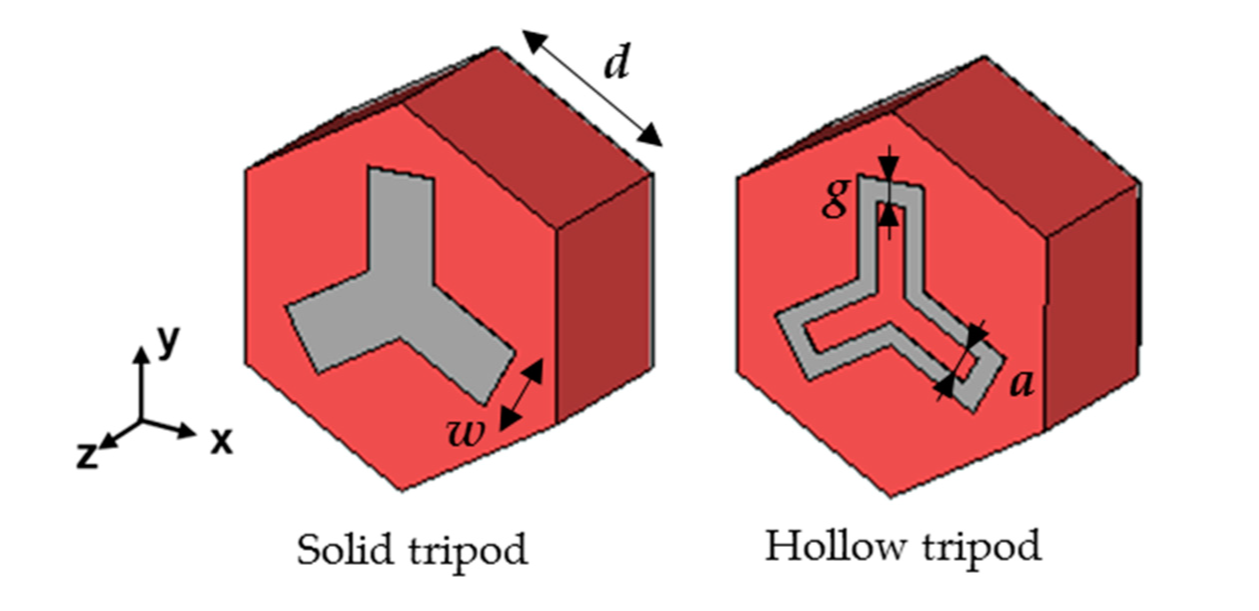
The metasensors proposed in this work are designed to operate in absorption within the THz band of 0.4–0.7 THz. All metastructures were configured as tri-layer designs consisting of a layer of aluminum (Al) metallic blades printed over a 150 µm thick polypropylene (PP) substrate with back metallization acting as a ground plane. It is important to note that metals within the designed THz frequency range can still be considered as conductors that can be modeled using finite conductivity [4,19], hence the back metallic sheet acts as a reflecting layer. The structure dimensions are: periodicity, d = 162.5 µm; distance between metallic strips, a = 26 µm; metallic strips width, g = 9.5 µm; metallic layers thickness, t = 0.4 µm; and blade width, w = 58.5 µm; as shown in Figure 1.
The designed metasurfaces are simulated using the commercial simulator CST Microwave Studio™. Floquet ports and periodic boundary conditions are applied to the designed unit cells to model the metasurfaces as an infinitely replicated array. The PP substrate was modeled as a low-loss dielectric with a complex relative permittivity εPP = 2.25(1 − j10−3). The aluminum used for the pattern and the ground plane was modeled as a lossy metal with electrical conductivity σ = 1.5 × 10⁷ S/m, as in [4,19] with the nominal conductivity of aluminum reduced to account for losses due to roughness. The metasurfaces were illuminated under normal incidence using a vertically polarized (Ey) plane wave. To evaluate the performance of the designed metasurfaces working as thin-film sensors, their outer face was coated with different thin-film thicknesses, ranging from 200 nm to 800 nm. The dielectric permittivity of the analyte used for this purpose was εa = 8, as this value has been used in other studies dealing with biosensing applications [19,20].
3. Results and Discussion
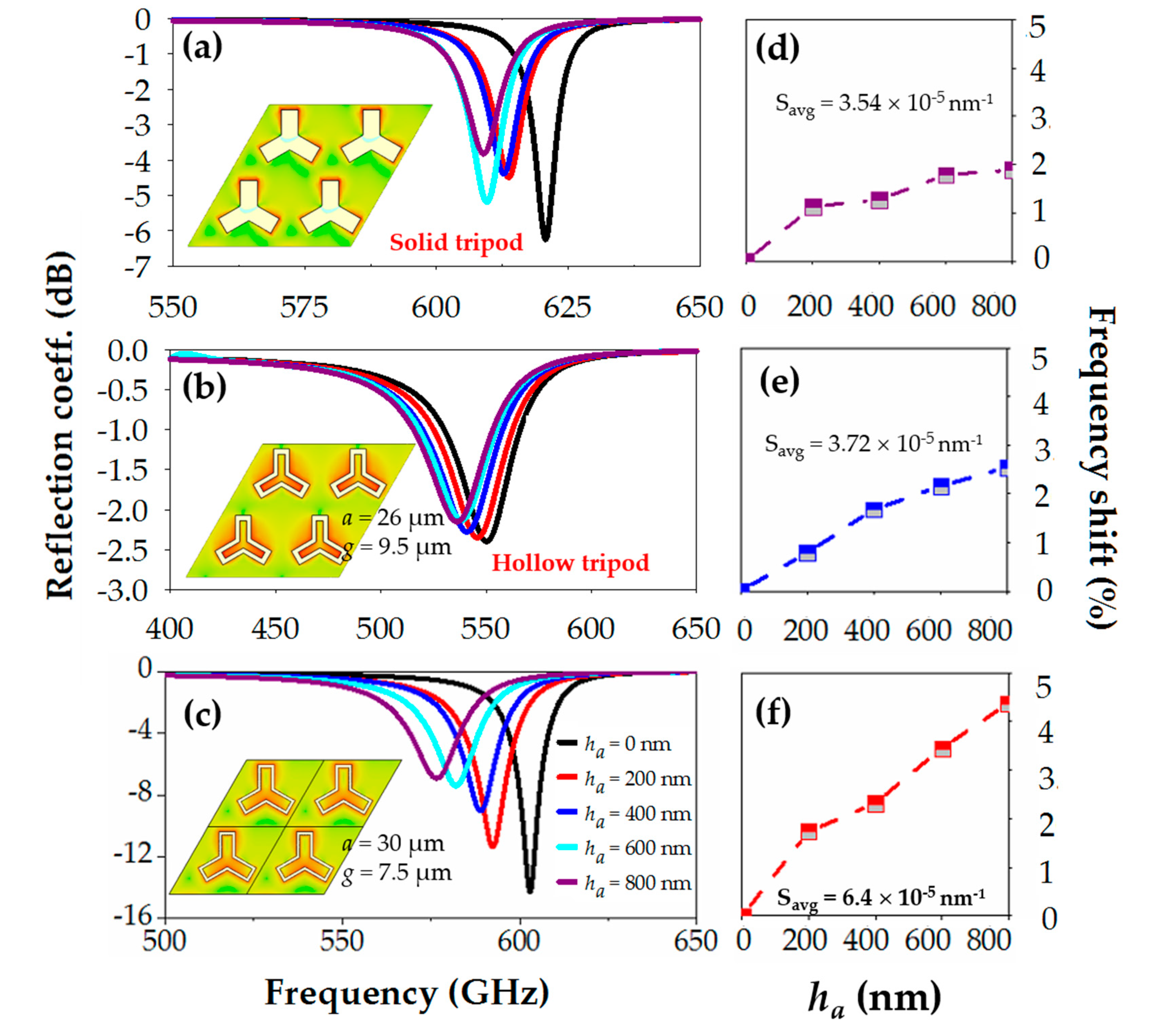
The numerical results of the reflection coefficient for the designed metasensors are shown in Figure 2. As shown in the figure (black curves), the response of the analyte-free metastructures exhibits a dip in the reflection coefficient at 551 GHz (hollow tripod, Figure 2b) and 620 GHz (solid tripod, Figure 2a). Before coating the surfaces with different analyte thicknesses, a study of the electric field distribution over the surface of the analyte-free structure was carried out, and the results are shown as insets in the same figure. As shown in Figure 2a,b, there are apparent differences between both metastructures. While in the solid tripod metastructure (Figure 2a) the electric field is confined only at the tips of the metallic blades, in the hollow tripod structure, the electric field is also confined inside the hollow blades, due to the capacitance generated between the metallic strips (see Figure 2b).
When using this type of unit cells for sensing applications, it becomes essential to have the maximum possible electric field concentration to increase the sensitivity to dielectric changes in the vicinity of its surface. The sensing performance of both metastructures was studied by coating them with a dielectric thin-film acting as an analyte, with dielectric permittivity εa = 8, and thicknesses ranging from ha = 200 nm to ha = 800 nm. The reflection spectra for the different analyte thicknesses are plotted in Figure 2a,c. As observed, a redshift of the resonance dip occurs when the analyte thickness increases, as expected. For completeness, this frequency shift as a function of the analyte thickness is plotted in Figure 2d,e where the redshift is clearly shown. To obtain a quantitative estimation of the sensing performance, we calculate the sensitivity of each structure, defined as S = (∆f/f0)/ha and measured in nm−1, where ∆f = f − f0, with f the resonance frequency for each analyte thickness, ha, and f0 the resonance frequency without the analyte. With this definition, we obtain an average sensitivity of 3.54 × 10⁻⁵ nm−1 for the solid tripod structure, and an average sensitivity of 3.72 × 10⁻⁵ nm−1 for the hollow tripod structure. These results translate into an improvement of the hollow structure of approximately 5% with respect to the solid tripod. As mentioned above, this can be because the electric field confinement is more distributed along the surface of the hollow tripod, making it more sensitive to changes in the refractive index around the surface of the structure.
The previous results suggest that one of the most critical factors for a good sensing device is to have large electric field confinement. To verify this, new metastructures were designed, based on the hollow tripod. First, we modify the strip width g (see dimensions in Figure 1) and the gap between strips, a, to optimize these parameters, and to achieve as deep a resonance as possible. Based on this analysis, it was found that the best dimensions are those in the inset of Figure 2e with: a = 30 µm and g = 7.5 µm. As observed in the curves of the reflection coefficient for different analyte thicknesses (Figure 2c), the frequency shift obtained is significantly larger than in the previous cases. Specifically, a maximum frequency shift of 4.36% is achieved for an analyte thickness of 800 nm (Figure 2f). This provides a mean sensitivity of 6.4 × 10⁻⁵ nm−1, giving rise to a 172% improvement regarding the hollow structure. In addition to being easy to design and manufacture, this structure is largely insensitive to the angle of polarization (as shown in the Supplementary Material), which is advantageous for sensing applications where it is vitally important to position the sample in the correct alignment.
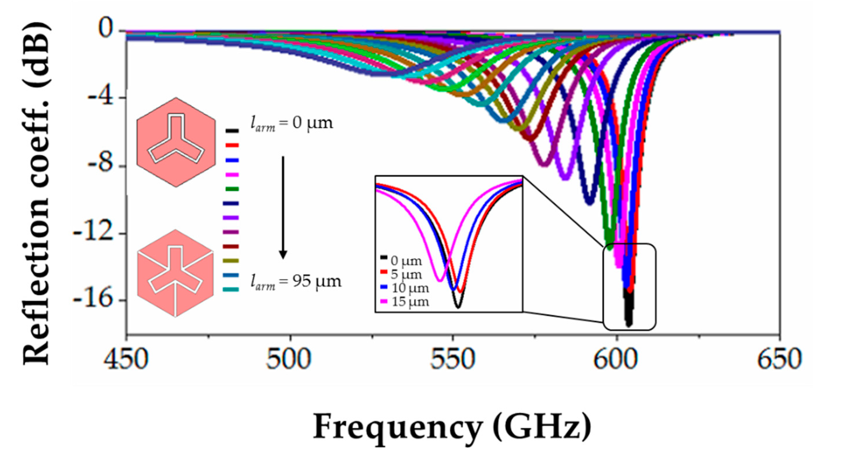
Once the optimal dimensions of the structure have been found, we continue this work by introducing changes in the design to improve the sensitivity and, therefore, the quality of the metasensor device. One way to enhance the electric field concentration is by adding arms to each of the three vertexes of the metallic pattern, as shown in the insets of Figure 3. In order to know the optimal length of these arms, we performed a parameter sweep of their length. The length of the arms (larm) varied from 5 µm up to the maximum, limited by the size of the unit cell, see Figure 3. The best results were achieved for an arm’s length equal to or less than 10 µm, obtaining a higher quality factor resonance in the bare structure. Thus, due to the greater ease of manufacture, we have chosen an arm’s length of 10 µm.
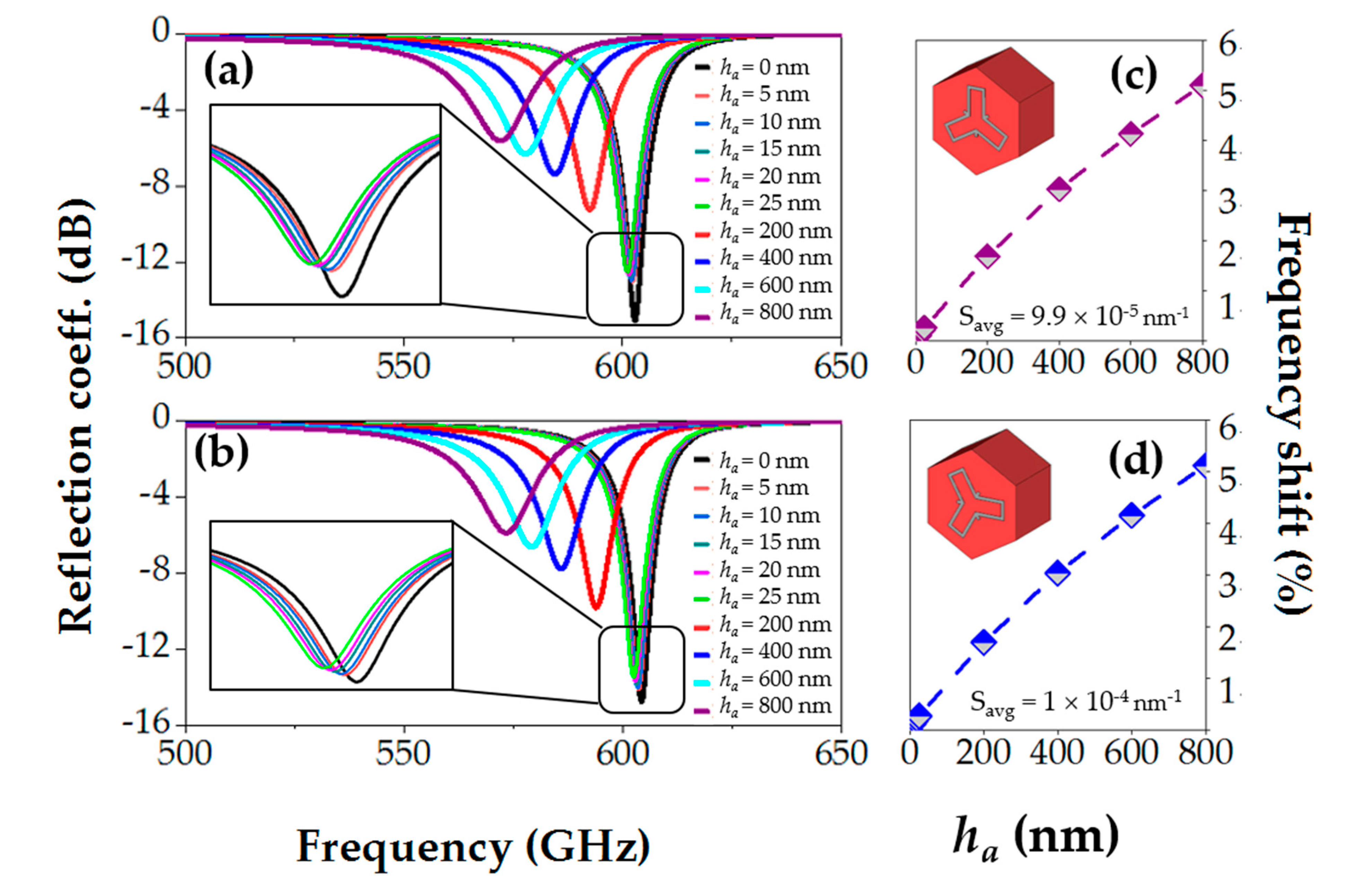
To compare the sensitivity achieved with the previous metastructures, we coated the new design with the same analyte thicknesses as before, obtaining the reflection coefficient results plotted in Figure 4a. When varying the analyte thickness between 200 and 800 nm, a maximum frequency shift of 5.09 GHz was obtained (see Figure 4c) with a mean sensitivity of 7.32 × 10⁻⁵ nm−1, leading to an improvement of 196% with respect to the hollow tripod. As can be observed in Figure 4a, this structure allows us to detect much thinner thicknesses than 200 nm, so we coated the structure with very thin films, with thicknesses ranging from 5 nm to 25 nm. The reflection coefficient and corresponding frequency shifts for these thicknesses can be seen in the inset of Figure 4a. With these results, we calculate a mean sensitivity of 1.27 × 10⁻⁴ nm−1 (improvement of 341% respect to the hollow tripod structure, which is not able to detect such ultrathin thicknesses, as shown in the supplementary material). As a final step, we rotate the metallic pattern of the metasurface unit cell 30° to perform the last comparison. The reflection coefficient and frequency shift achieved are shown in Figure 4b,d. As observed, the performance of this design is similar to the previous one (without rotation), which agrees with the results found in [21] for single particles (non-periodic) plasmonic tripods with C3 rotational symmetry. If we calculate the maximum frequency shift and the mean sensitivity again, the resulting values are 5.1 GHz, and 7.35 × 10⁻⁵ nm−1 for analyte thicknesses between 200 and 800 nm, respectively, which are approximately identical to the previous case. The mean sensitivity with very thin films (5 to 25 nm) was also calculated obtaining a mean value of 1.42 × 10⁻⁴ nm−1, leading to an improvement of 381% with respect to the hollow tripod, and thus becoming the best option for sensing applications. Table 1 summarizes the maximum frequency shift and sensitivity achieved for the different metastructures studied in this work.
As a final step, a comparison with other works found in the literature was carried out, in which similar designs in terms of complexity and dimensions were analyzed (note that we tried to keep the dimensions compatible with standard photolithography techniques). To make a fair comparison of all designs, we used a new sensitivity definition that also takes into account the operational frequency, and the analyte refractive index (otherwise, we would be benefiting those works in which the refractive index is higher) as S = (∆f/f0)/(ha·na), with ha the analyte thickness, and na the analyte refractive index. This comparison can be seen in Table 2. As shown, this work could be on the top of the ranking, achieving a high sensitivity for thicknesses of analyte several orders lower than other designs. A possible explanation for this better performance could be that the hollow tripod has a field distribution with more distributed hot spots along the unit cell and not concentrated at small areas, similar to what happened in our previous paper [4].
4. Conclusions
To conclude, we have reported in this work three different tripod-based metasurfaces working as thin-film sensors in the THz band. We have shown that the higher electric field concentration on the surfaces, the larger the frequency shift, and sensitivity results. To corroborate this fact, two different metastructures have been initially studied, a solid tripod and a hollow tripod metasurface, with higher electric field confinement, obtaining average sensitivities of 3.54 × 10⁻⁵ nm−1 and 3.72 × 10⁻⁵ nm−1, respectively. Other metastructures have been designed, to improve the sensitivity, by changing the unit cell parameters, including additional elements in the metallic pattern of the unit cell, such as arms, or rotating the structure pattern, thus obtaining the best design with an average sensitivity of 1.42 × 10⁻⁴ when measuring extremely thin analytes, meaning an improvement of 381% with respect to the initial hollow tripod structure. Finally, we have performed a comparison with other designs found in the literature, with similar complexity and dimensions, showing that our designed structure is on top of the list, improving most of the previous works by more than one order of magnitude. These results emphasize the importance of using metastructures with complex geometries for sensing applications, in which the electric field is distributed throughout the surface and not only at discrete points, such as metageometries.
Supplementary Materials
The following are available online at https://0-www-mdpi-com.brum.beds.ac.uk/2076-3417/10/18/6504/s1: Figure S1: Spectral transmission of the simple tripod metasurface plotted as a function of the polarization angle. Figure S2: Reflection coefficient for different ultrathin analyte thicknesses.
Author Contributions
Conceptualization, I.J.-L, B.O., V.P.-P. and M.B.; methodology, I.J.-L. and M.B.; software, I.J.-L.; validation, B.O., V.P.-P. and M.B.; formal analysis, I.J.-L, B.O., V.P.-P. and M.B.; investigation, I.J.-L, B.O., V.P.-P. and M.B.; resources, I.J.-L, B.O., V.P.-P. and M.B.; data curation, I.J.-L.; writing—original draft preparation, I.J.-L. and M.B.; writing—review and editing, I.J.-L, B.O., V.P.-P. and M.B.; visualization, I.J.-L.; supervision, B.O., V.P.-P. and M.B.; project administration, M.B.; funding acquisition, M.B. All authors have read and agreed to the published version of the manuscript.
Funding
This research was funded by Spanish Ministerio de Ciencia, Innovación y Universidades, Project RTI2018-094475-B-I00 (MCIU/AEI/FEDER,UE).
Conflicts of Interest
The authors declare no conflict of interest. The funders had no role in the design of the study; in the collection, analyses, or interpretation of data; in the writing of the manuscript; or in the decision to publish the results.
References
- Ho, L.; Pepper, M.; Taday, P. Terahertz spectroscopy: Signatures and fingerprints. Nat. Photon. 2008, 2, 541–543. [Google Scholar] [CrossRef] [Green Version]
- Saeedkia, D. Handbook of Terahertz Technology for Imaging, Sensing and Communications; WP Woodhead Publishing: Cambridge, UK, 2013; ISBN 9780857092359. [Google Scholar]
- Yan, X.; Yang, M.; Zhang, Z.; Liang, L.; Wei, D.; Wang, M.; Zhang, M.; Wang, T.; Liu, L.; Xie, J.; et al. The terahertz electromagnetically induced transparency-like metamaterials for sensitive biosensors in the detection of cancer cells. Biosens. Bioelectron. 2019, 126, 485–492. [Google Scholar] [CrossRef] [PubMed]
- Jáuregui-López, I.; Rodríguez-Ulibarri, P.; Urrutia, A.; Kuznetsov, S.A.; Beruete, M. Labyrinth Metasurface Absorber for Ultra-High-Sensitivity Terahertz Thin Film Sensing. Phys. Status Solidi Rapid Res. Lett. 2018, 12, 1800375. [Google Scholar] [CrossRef]
- Beruete, M.; Jáuregui-López, I. Terahertz Sensing Based on Metasurfaces. Adv. Opt. Mater. 2019, 1900721, 1900721. [Google Scholar] [CrossRef] [Green Version]
- Papari, G.P.; Koral, C.; Andreone, A. Encoded-enhancement of THZ metasurface figure of merit for label-free sensing. Sensors 2019, 19, 2544. [Google Scholar] [CrossRef] [Green Version]
- Islam, M.S.; Sultana, J.; Biabanifard, M.; Vafapour, Z.; Nine, M.J.; Dinovitser, A.; Cordeiro, C.M.B.; Ng, B.W.H.; Abbott, D. Tunable localized surface plasmon graphene metasurface for multiband superabsorption and terahertz sensing. Carbon 2020, 158, 559–567. [Google Scholar] [CrossRef]
- Rodríguez-Ulibarri, P.; Kuznetsov, S.A.; Beruete, M. Wide angle terahertz sensing with a cross-dipole frequency selective surface. Appl. Phys. Lett. 2016, 108, 111104. [Google Scholar] [CrossRef]
- Srivastava, Y.K.; Cong, L.; Singh, R. Dual-surface flexible THz Fano metasensor. Appl. Phys. Lett. 2017, 111, 1–6. [Google Scholar] [CrossRef]
- Gupta, M.; Srivastava, Y.K.; Manjappa, M.; Singh, R. Sensing with toroidal metamaterial. Appl. Phys. Lett. 2017, 110, 121108. [Google Scholar] [CrossRef]
- Hong, J.T.; Jun, S.W.; Cha, S.H.; Park, J.Y.; Lee, S.; Shin, G.A.; Ahn, Y.H. Enhanced sensitivity in THz plasmonic sensors with silver nanowires. Sci. Rep. 2018, 8, 1–8. [Google Scholar] [CrossRef] [Green Version]
- Srivastava, Y.K.; Ako, R.T.; Gupta, M.; Bhaskaran, M.; Sriram, S.; Singh, R. Terahertz sensing of 7 nm dielectric film with bound states in the continuum metasurfaces. Appl. Phys. Lett. 2019, 115, 1–17. [Google Scholar] [CrossRef] [Green Version]
- O’Hara, J.F.; Withayachumnankul, W.; Al-Naib, I.A.I. A Review on Thin-film Sensing with Terahertz Waves. J. Infrared Millim. Terahertz Waves 2012, 33, 245–291. [Google Scholar] [CrossRef]
- Singh, R.; Cao, W.; Al-Naib, I.A.I.; Cong, L.; Withayachumnankul, W.; Zhang, W. Ultrasensitive terahertz sensing with high- Q Fano resonances in metasurfaces. Appl. Phys. Lett. 2014, 105, 171101. [Google Scholar] [CrossRef] [Green Version]
- Kim, N.; In, S.; Lee, D.; Rhie, J.; Jeong, J.; Kim, D.S.; Park, N. Colossal Terahertz Field Enhancement Using Split-Ring Resonators with a Sub-10 nm Gap. ACS Photon. 2018, 5, 278–283. [Google Scholar] [CrossRef]
- Cong, L.; Tan, S.; Yahiaoui, R.; Yan, F.; Zhang, W.; Singh, R. Experimental demonstration of ultrasensitive sensing with terahertz metamaterial absorbers: A comparison with the metasurfaces. Appl. Phys. Lett. 2015, 106, 031107. [Google Scholar] [CrossRef]
- Jáuregui-López, I.; Rodríguez-Ulibarri, P.; Kuznetsov, S.A.; Nikolaev, N.A.; Beruete, M. THz Sensing With Anomalous Extraordinary Optical Transmission Hole Arrays. Sensors 2018, 18, 3848. [Google Scholar] [CrossRef] [Green Version]
- Xu, W.; Xie, L.; Zhu, J.; Tang, L.; Singh, R.; Wang, C.; Ma, Y.; Chen, H.T.; Ying, Y. Terahertz biosensing with a graphene-metamaterial heterostructure platform. Carbon 2019, 141, 247–252. [Google Scholar] [CrossRef]
- Jáuregui-López, I.; Rodríguez-Ulibarri, P.; Kuznetsov, S.A.; Quemada, C.; Beruete, M. Labyrinth Metasurface for Biosensing Applications: Numerical Study on the New Paradigm of Metageometries. Sensors 2019, 19, 4396. [Google Scholar] [CrossRef] [Green Version]
- Park, S.J.; Hong, J.T.; Choi, S.J.; Kim, H.S.; Park, W.K.; Han, S.T.; Park, J.Y.; Lee, S.; Kim, D.S.; Ahn, Y.H. Detection of microorganisms using terahertz metamaterials. Sci. Rep. 2014, 4, 4988. [Google Scholar] [CrossRef]
- Pacheco-Peña, V.; Fernández-Domínguez, A.I.; Luo, Y.; Beruete, M.; Navarro-Cía, M. Aluminum Nanotripods for Light-Matter Coupling Robust to Nanoemitter Orientation. Laser Photon. Rev. 2017, 11, 1700051. [Google Scholar] [CrossRef]
- Jin, B.; Tan, W.; Zhang, C.; Wu, J.; Chen, J.; Zhang, S.; Wu, P. High-Performance Terahertz Sensing at Exceptional Points in a Bilayer Structure. Adv. Theory Simul. 2018, 1, 1800070. [Google Scholar] [CrossRef]
- Janneh, M.; De Marcellis, A.; Palange, E.; Tenggara, A.T.; Byun, D. Design of a metasurface-based dual-band Terahertz perfect absorber with very high Q-factors for sensing applications. Opt. Commun. 2018, 416, 152–159. [Google Scholar] [CrossRef]
- Al-Naib, I. Evaluation of amplitude difference referencing technique with terahertz metasurfaces for sub-micron analytes sensing. J. King Saud Univ. Sci. 2019, 31, 1384–1387. [Google Scholar] [CrossRef]
Figure 1.
Front view of the designed tripod metasurfaces unit cells. Metallization is represented in grey and polypropylene (PP) substrate in red.
Figure 1.
Front view of the designed tripod metasurfaces unit cells. Metallization is represented in grey and polypropylene (PP) substrate in red.

Figure 2.
Reflection coefficient for different analyte thicknesses: 0 nm (black line), 200 nm (red line), 400 nm (blue line), 600 nm (cyan line), and 800 nm (dark pink line), for the solid tripod structure (a), and the hollow tripod structures (b,c). Insets: electric field magnitude over the empty (analyte-free) tripod metasurfaces. Frequency shift as a function of the analyte thickness, for extremely thin analytes with average sensitivity for the solid tripod structure (d), and the hollow tripod structures (e,f).

Figure 3.
Reflection coefficient for different arm lengths (linear sweep from 0 to 95 µm) of the hollow tripod structure. Insets: schematic representation for arm lengths of 0 µm (top) and 95 µm (bottom).
Figure 3.
Reflection coefficient for different arm lengths (linear sweep from 0 to 95 µm) of the hollow tripod structure. Insets: schematic representation for arm lengths of 0 µm (top) and 95 µm (bottom).

Figure 4.
Reflection coefficient for different analyte thicknesses for the hollow tripod structure with arms (a), and the hollow tripod structure with arms, and rotated (b). Insets: zoom of the reflection coefficient for both metastructures and extremely thin film analytes (0–25 nm). Frequency shift as a function of the analyte thickness, with average sensitivity for the hollow tripod structure with arms (c), and the hollow tripod structure with arms, and rotated (d).


Table 1.
Comparison of the most relevant quality parameters of the three tripod-metastructures studied in this work when working as thin-film sensors where the analyte thickness deposited varies between 200 and 800 nm (top), and for ultra-thin analytes between 5 and 25 nm (bottom).
Table 1.
Comparison of the most relevant quality parameters of the three tripod-metastructures studied in this work when working as thin-film sensors where the analyte thickness deposited varies between 200 and 800 nm (top), and for ultra-thin analytes between 5 and 25 nm (bottom).
| ha (nm) | Tripod Structure | ∆f max (%) | Mean Sensitivity (nm−1) |
|---|---|---|---|
| 200–800 | Solid | 1.89 | 3.54 × 10⁻⁵ |
| Hollow a = 26 µm | 2.55 | 3.72 × 10⁻⁵ | |
| Hollow a = 30 µm | 4.36 | 6.40 × 10⁻⁵ | |
| Hollow + arms | 5.09 | 7.32 × 10⁻⁵ | |
| Hollow + arms, rotated | 5.11 | 7.35 × 10⁻⁵ | |
| 5–25 | Hollow + arms | 0.50 | 1.27 × 10⁻⁴ |
| Hollow + arms, rotated | 0.60 | 1.42 × 10⁻⁴ |
Table 2.
Comparison of different values of sensitivity achieved in different works, calculated as S = (∆f/f0)/(ha·na), with ha the analyte thickness and na the analyte refractive index, in refractive index units (RIU), and ordered chronologically.
Table 2.
Comparison of different values of sensitivity achieved in different works, calculated as S = (∆f/f0)/(ha·na), with ha the analyte thickness and na the analyte refractive index, in refractive index units (RIU), and ordered chronologically.
| Reference | ha (nm) | na (RIU) | f0 (GHz) | ∆f (GHz) | Sensitivity (nm·RIU)−1 |
|---|---|---|---|---|---|
| Ref [22], 2018 | 2000 | 1.01 | 2250 | 16 | 3.52 × 10⁻⁶ |
| Ref [23], 2018 | 16 000 | 1.6 | 2260 | 200 | 3.45 × 10⁻⁶ |
| Ref [24], 2019 | 250 | 1.6 | 396 | 1 | 6.3 × 10⁻⁶ |
| Ref [7], 2019 | 10 000 | 1.4 | 1550 | 10 | 4.6 × 10⁻⁷ |
| Ref [12], 2019 | 7 | 8 | 1000 | 3 | 5.35 × 10⁻⁵ |
| This work | 5 | √8 | 604 | 0.6 | 7 × 10⁻⁵ |
© 2020 by the authors. Licensee MDPI, Basel, Switzerland. This article is an open access article distributed under the terms and conditions of the Creative Commons Attribution (CC BY) license (http://creativecommons.org/licenses/by/4.0/).
Share and Cite
MDPI and ACS Style
Jáuregui-López, I.; Orazbayev, B.; Pacheco-Peña, V.; Beruete, M. Tripod-Loop Metasurfaces for Terahertz-Sensing Applications: A Comparison. Appl. Sci. 2020, 10, 6504. https://0-doi-org.brum.beds.ac.uk/10.3390/app10186504
AMA Style
Jáuregui-López I, Orazbayev B, Pacheco-Peña V, Beruete M. Tripod-Loop Metasurfaces for Terahertz-Sensing Applications: A Comparison. Applied Sciences. 2020; 10(18):6504. https://0-doi-org.brum.beds.ac.uk/10.3390/app10186504
Chicago/Turabian StyleJáuregui-López, Irati, Bakhtiyar Orazbayev, Victor Pacheco-Peña, and Miguel Beruete. 2020. "Tripod-Loop Metasurfaces for Terahertz-Sensing Applications: A Comparison" Applied Sciences 10, no. 18: 6504. https://0-doi-org.brum.beds.ac.uk/10.3390/app10186504
Note that from the first issue of 2016, this journal uses article numbers instead of page numbers. See further details here.