A Refined Shape Sensing Method for Skin Antenna Structure Based on Inverse Finite Element Method

1
Key Laboratory of Electronic Equipment Structure Design of Ministry of Education, Xidian University, Xi’an 710071, China
2
724th Research Institute of China State Shipbuilding Corporation Limited; Nanjing 211100, China
*
Author to whom correspondence should be addressed.
Appl. Sci. 2020, 10(21), 7620; https://0-doi-org.brum.beds.ac.uk/10.3390/app10217620
Submission received: 3 August 2020
/
Revised: 30 September 2020
/
Accepted: 18 October 2020
/
Published: 29 October 2020
(This article belongs to the Special Issue Design, Analysis, and Measurement of Antennas)
Abstract
:An important issue in the existing inverse finite element method (iFEM) is that reconstruction accuracy cannot satisfy the analytical demand for the flexible structure. To address this issue, this paper presents a multi-nodes iFEM that reconstructs the displacement of structure based on surface measurement strains in real time. Meanwhile, in light of the response characteristics of iFEM, an innovative interpolation method is adapted to regenerate the full field deformation again. The proposed method substantially expands the size of inverse elements, which reduces the numbers of sensors and improves the reconstruction accuracy. The effectiveness of the method to predict displacement is verified by a flexible antenna panel subjected typical boundary conditions.
1. Introduction
Today, with the rapid development of integrated antenna of radar technology, morphing-wing-embedded antenna arrays have an extensive application, such as military and civilian aerospace [1]. However, these structures are subjected to complex loads, such as wind and atmospheric pressure, which will produce various types of deformation leading to decrease the pointing accuracy of array antenna dramatically [2]. Therefore, real-time measurement of the deformation of antenna unit, which provides feedback to actuation and control systems of structure, is significant for human and environment safety [3,4].
The method on dynamically monitoring the deformation of structure, known as shape sensing, and the process of precisely approximating the integrated displacements based on strain measurement belongs to strictly the inverse problem [5]. To settle the inverse problem, Tikhonov et al. proposed a method included a regularization term to enhance the smoothness degree for approximating solution [6], and the technique was extensively employed for the inverse procedure. During the past few decades, the utilization of shape sensing algorithms for practical engineering has been demonstrated extensively. However, these approaches are mainly classified into the inverse finite element method (iFEM), modal method, and Ko’s displacement method. Haugse and Foss proposed a modal method derived from the idea of polynomial basis function or spline function interpolation [7], which establishes the relationship between strain and deformation mode coordinates explicitly. Reference [8] use the modal method to reconstruct the displacement field of the beam structure precisely. However, the reconstruction accuracy is strictly limited on the number of sensors, which are at least higher than the mode orders extracted from structure. Thus, the method inevitably needs a high fidelity physical model, which is hard to do outside the laboratory environment. Then, Ko et al. develop a strategy, referred to as Ko’s displacement method [9], which is based on the Euler–Bernoulli beam theory, and are extensively applicable to structural reconstruction such as beams, wing-boxes, and plates. The technique included the displacement superposition principle, which builds the quantitative relation about strain and element degrees of freedom definitely, resulting in the true shape sensing of slender structures. References [10,11] employ the numerical and experimental means to examine its feasibility. Although the method has a sufficiently accurate reconstruction of a slender structure, it is not suitable for the regeneration of three-dimensional structures. Hence, a well-suited shape-sensing algorithm, in addition to satisfying high accuracy, fast calculation, and strong robustness, also needs to consider the complexity of structural boundary conditions and geometric topology. Due to the deficiencies of the modal and the KO method, they are not suited for broad use in the field of structural health monitoring (SHM). Tessler and Spangler proposed an innovative methodology [12], named the inverse finite element method (iFEM), embodying the aforementioned characteristics required for a powerful SHM algorithm. The technology is based on the minimization of weighted-least-squares functional, which generally is applicable to complex structures subjected to complicated boundary conditions at any time [13]. The framework is sufficiently precise, powerful, and fast for applications in an engineering structure loaded statically and dynamically. Furthermore, the strain–displacement relationship was merely considered in the formulation, and materials of structure can be strictly ignored [14]. Benefiting from the potentiality of iFEM, the complex structure can be equivalent to simple models topologically, such as beam, plate, or shell. Moreover, based on the kinematic assumption of the Timoshenko beam theory, an inverse frame finite element is developed by Cerracchio and Gherlone [15]. References [16,17,18,19] have some analyses of three-dimensional frame structures under static or damped harmonic excitations based on strains produced numerically and experimentally. Based on the kinematic assumptions of the first-order shear deformation theory (FSDT), Tessler et al. developed three-node inverse shell element shorted form iMIN3 [20], which profiles the complex plate and shell structures accurately. Kefal et al. formulated a four-node quadrilateral inverse-shell element [21], which takes the influence of hierarchical drilling rotation into account, avoiding the occurrence of the singular value well. However, due to the heterogeneous and anisotropy of composite and sandwich structures, iFEM based on FSDT may result in slightly insufficient estimates for shape sense. Then, based on Zigzag displacement deformation theory, Cerracchio et al. and Kefal et al. improved the iFEM, which is suitable for sensing complex structures [22,23].
As mentioned above, the iFEM has prominent advantages, such as robustness, efficiency, and real-time response. However, the method needs numbers of inverse elements for shape sensing of flexible structures, leading to increasing the quantities of installing sensor. Therefore, the method is not directly suitable for a sophisticated antenna structure. This paper establishes a novel interpolation method to regenerate the structural deformation field based on data from the multi-node inverse finite element method. The technology optimally compromises the number of sensors and the inverse element and simultaneously retains the reconstruction accuracy.
The outline of the paper can be summarized as follows. First, the deformation field theory for plate is presented, and the multi-node iFEM formula is derived based on first-order shear deformation theory (FSDT). Second, taking the five-node quadrilateral inverse finite element as numerical implementation to result in the structure deformation. After that, the displacement field of the practical antenna panel is generated by the proposed method by experimental and numerical analysis approaches, respectively. According to some response dates from iFEM, the utilization of the innovative fitting technology restructured the full deformation field of board very well. The results from numerical and experimental analysis verify the correctness of the method proposed. Finally, the conclusions about the superiorities of the refined restructure methodology are emphasized.
2. Inverse Finite Element Formulation
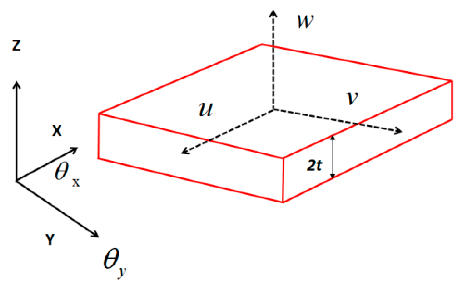
Consider a plate with thickness of 2t as the analytical model, and the structure can be described by the general Cartesian coordinate system, as shown in Figure 1.
According to the Mindlin plate theory, the three-directional displacements relevant to arbitrary points can be expressed [13].
where, are the plane displacements and is the transverse displacement across the thickness orientation; are rotations around the x- and y-axes, respectively; and z is the distance from the selected points to mid-plane of the structure.
The linear strain components are expressed by appropriate derivatives of the displacements.
where, indicates membrane, bending curvatures, and transverse-shear strain measures, respectively.
According to the strain relation between any point and three main directions from material mechanics, the strain at any point of structure can be expressed.
Based on the functional theory, the Euclidean distance relationship between the measured strain and the theoretical strain can be expressed.
The is the measured strain from sensor, is the theoretical strains associated with location, which is pasted angle along axis (x, y, z), respectively, and denotes the numbers of sensors, is the weighting constants controlling the completeness between the analytic strains and their experimentally measured values.
Based on interpolation method, the deformation of points in the element can be expressed linearly by the shape function of element and the deformation of nodes. The result of any points in element can be expressed as follows:
where, indicates the interpolation shape function of element, is the numbers of element nodes, and is the degree of freedom of element node expressed by nodal vector.
Introducing Equations (4) and (5) and into Equation (6), and taking the minimum value of it about node degrees of freedom, gives rise to the function of shape sensing simultaneously.
where, is the element matrix related to only the location layout of strain sensors and the vector is a function of the number of strain sensors in the element as well as the measured angle values. These can be explicitly written, respectively, as
where, can be listed by Appendix A, is the angle cosine vector, and is usually assigned a minimum value [13].
When the element matrix equations are established, the global deformation field can be performed explicitly according to the transformation relationship from the local to global coordinates.
As K includes the rigid body motion mode of the discretized structure, therefore, it is a singular matrix. By combining problem-specific displacement boundary conditions, the resulting system of equations can be reduced from Equation (12)
where, is a square matrix and invertible [13,24], is a matrix, and is a vector. The solution of Equation (12) is very efficient, because the matrix remains unchanged for a determined configuration of sensors in the process of constant deformation. Moreover, needs to be updated during any deformation cycle in real time. Finally, the unknown vector reflects the structural state as well at any time.
According to general space interpolation methods, all the methods satisfy the estimation formula [25]
where is the response value at the interpolated point in the structure, indicates weighting function associated to the i-th sample point corresponding to the value , and m represents the numbers of sampling points.
However, the inverse elements divided are evidently bigger than that fem, and the full field deformation obtained by Equation (12) has a distinct difference. The approximation approach is not suited for larger inverse elements. Based on the idea of constructing shape function shown [26], one can adapt a refined interpolation function that the nodes may be in the element rather than only in the boundary. The method employs the properties of shape function to improve the precision for a specific problem. The shape function can be described in the discrete vector
where is node shape function, is the coordinate in the element, indicates the number of selected positions, and the arbitrarily point of the structure is expressed according to the interpolation definition
The interpolation methods satisfy the four properties on shape function, and the geometric characteristics of the structure are described in some sense, overcoming the deficiency of little physical significances.
3. Numerical and Experimental Examples
The deformation of the antenna reflector is the main factor that affects pointing accuracy In order to examine the accuracy of iFEM for reconstructing the deformation of the antenna plate, an analysis between numerical and experiment on the skin antenna plate was presented.
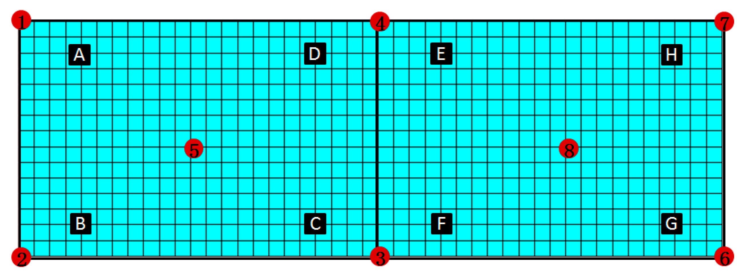
A rectangular plate has a length of 0.560 m, a height of 0.202 m, and a uniform thickness of 3.2 mm. The plate has an elastic modulus of 1.0 GPa and a Poisson’s ratio of 0.3 and is meshed 675 quadrilateral elements in analysis software; however, the structure was divided only two inverse quadrilateral elements (shown Figure 2). In Figure 2, the numbers in red indicate the element nodes, and the square letters in black denote the sampling points, respectively.
First, the deformation of sampling points can be obtained by iFEM. Second, based on these results, the whole deformation field can be reconstructed by the interpolation method proposed above. The deformations with two different boundary constraints are analyzed—namely, the left side of the structure—and both ends are fixed respectively.
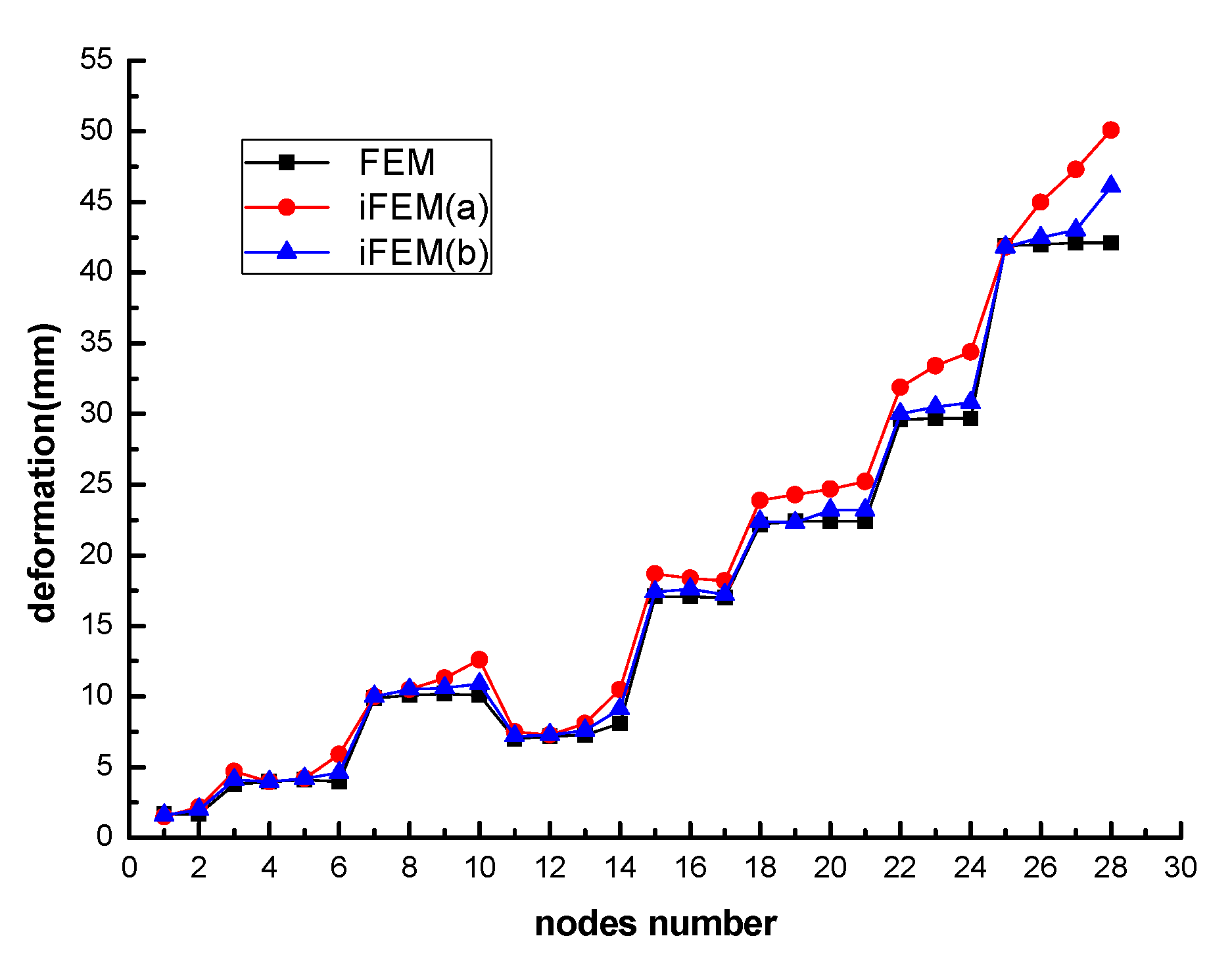
With the condition of complete constraints at line connected node 1 and 2, the concentrated force of 10N is applied positive at nodes 5 and negative 10N at nodes 8 in the z direction concurrently. The nodes’ deformations calculated by iFEM together with FEM are shown in Table 1.
Based on the values of nodes 3–8 by iFEM, one can obtain the sample points A–H by the general interpolation method. Moreover, acting the nodes A–H together with 5 and 8 as sampling points, one can regenerate the full-field deformation with the proposed interpolation framework. The deformation of the whole structure from FEM and iFEM are presented in Figure 3.
Figure 3 shows the deformed shapes of the plate obtained by different approaches shown from three different colors lines. The x-axis indicates the points of structure-expressed finite numbers, and y-axis is the deformation. According to the various interpolation means, iFEM(a) reflects the deformation trend of the whole structure according to the Equation (13), and iFEM(b) does that by Equation (15), respectively.
In order to quantitatively analyze the validity of the proposed method, the evaluation indexes mean error of nodes (ME) and root mean square (RMS) are introduced.
where, indicates the value provided by the finite element method, is the value from the inverse finite element method, and are the number of nodes and sample points, respectively.
Considering the values from FEM as references, Table 1 lists the results from iFEM. The maximum deformation of the node along the z direction is 50.2 mm, and the maximum percentage difference is 8. The reconstruction is 1.87 mm, and the RMS of the reconstruction accuracy is 2.57 mm from iFEM(a). However, based on the proposed method, the RMS value of the deformation reconstruction accuracy is 1.0 mm.
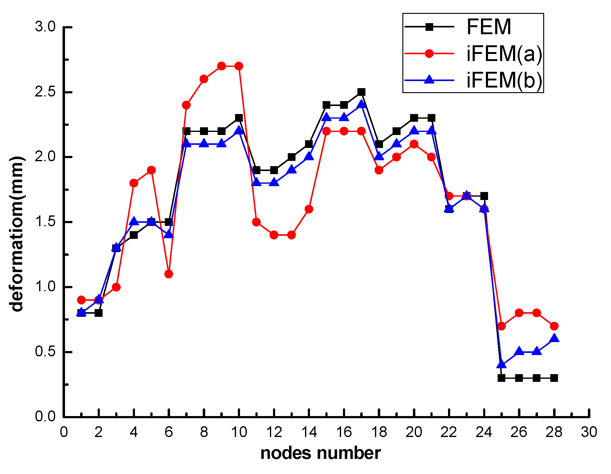
With case two, lines connected nodes 1 and 2, and at the same time, 6 and 7 are fixed completely, so the concentrated force of 10N at node 5 and 10N at nodes 8 are applied in the positive z direction. In comparison, the deformation values of nodes are listed in Table 2. Based on these dates, the profile of structure can be reconstructed again by iFEM(b), as shown in Figure 4.
Table 2 displays the results from two approaches. The maximum deflection of the nodes is 2.5 mm, and the maximum deviation is 0.1 mm. The reconstruction is 0.3 mm, and the RMS of reconstruction accuracy is 0.3 mm. However, adopting the refined method, the RMS value of the deformation reconstruction accuracy decreases 0.1 mm.
Figure 3 and Figure 4 depict the total deformed shapes of the plate employing different interpolation technologies iFEM(a) and iFEM(b) separately. For a view of profiles approaching FEM, the improved approximating skill raises the reconstruction accuracy dramatically.
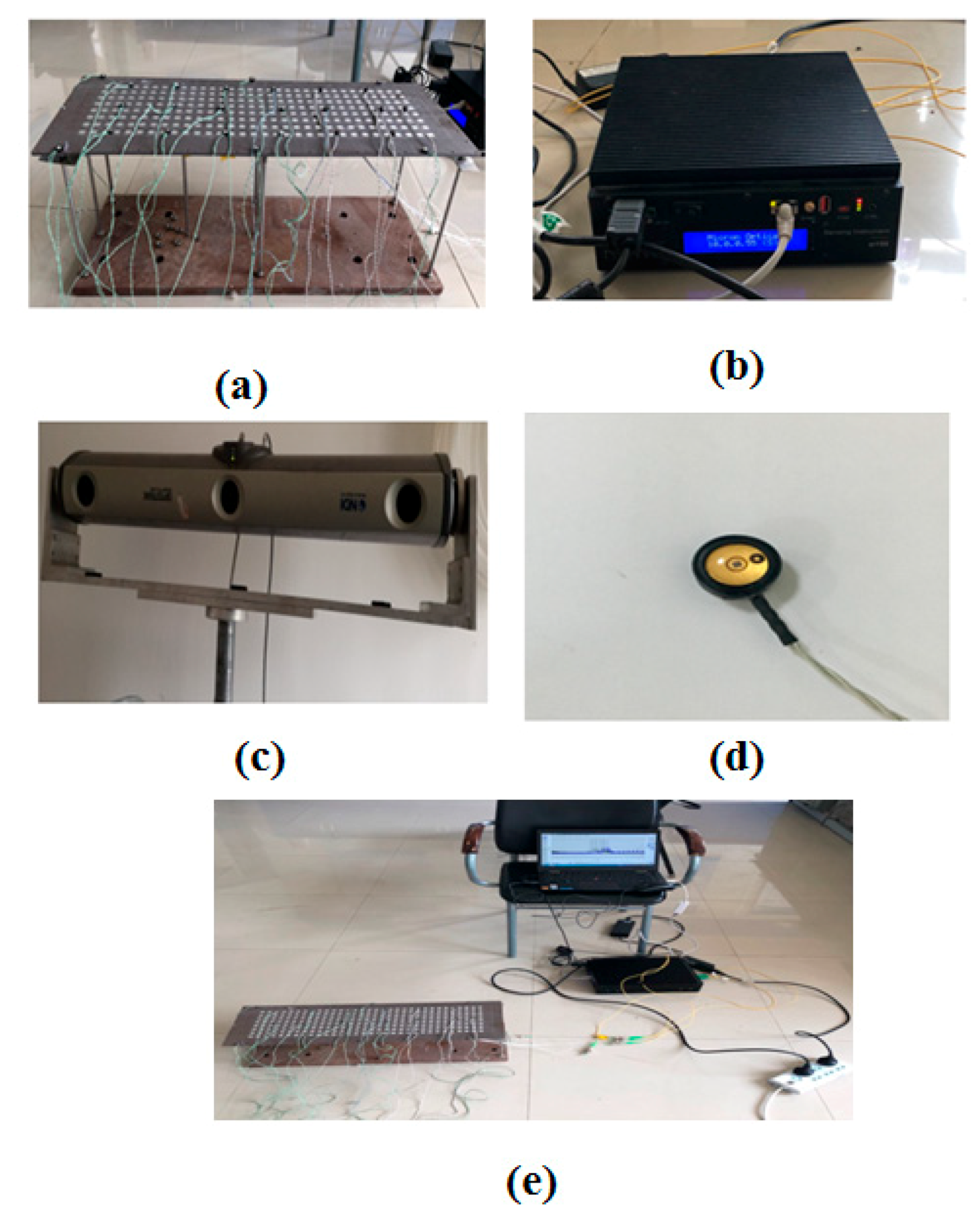
In this section, one part of the antenna plate is considered. For the purpose of demonstrating the effectiveness put forward above, the panel has a length of 0.560 m, a height of 0.200 m, and a uniform thickness of 3.2 mm. For the aim of according with the simulated condition, 11 holes were arranged on the board, which was connected to fixed base by way of a bolt and screw. Meanwhile, the magnitude of the load is controlled by adjusting the nut up and down. The fixed device is shown (Figure 5a).
According to the location sensors configuration from the simulation model, the fiber grating sensors are pasted at the corresponding positions of the experimental board one by one, and the markers with functions of photosensitization are pasted on the surface of the plate (Figure 5d). The variation of three-dimensional coordinates can be tracked by a 3D measurement system supplied by NDI (Waterloo, Ontario, Canada) (Figure 5c), and the surface strain date of structure can be read by the Fiber Bragg Grating (FBG) demodulator (Figure 5b).
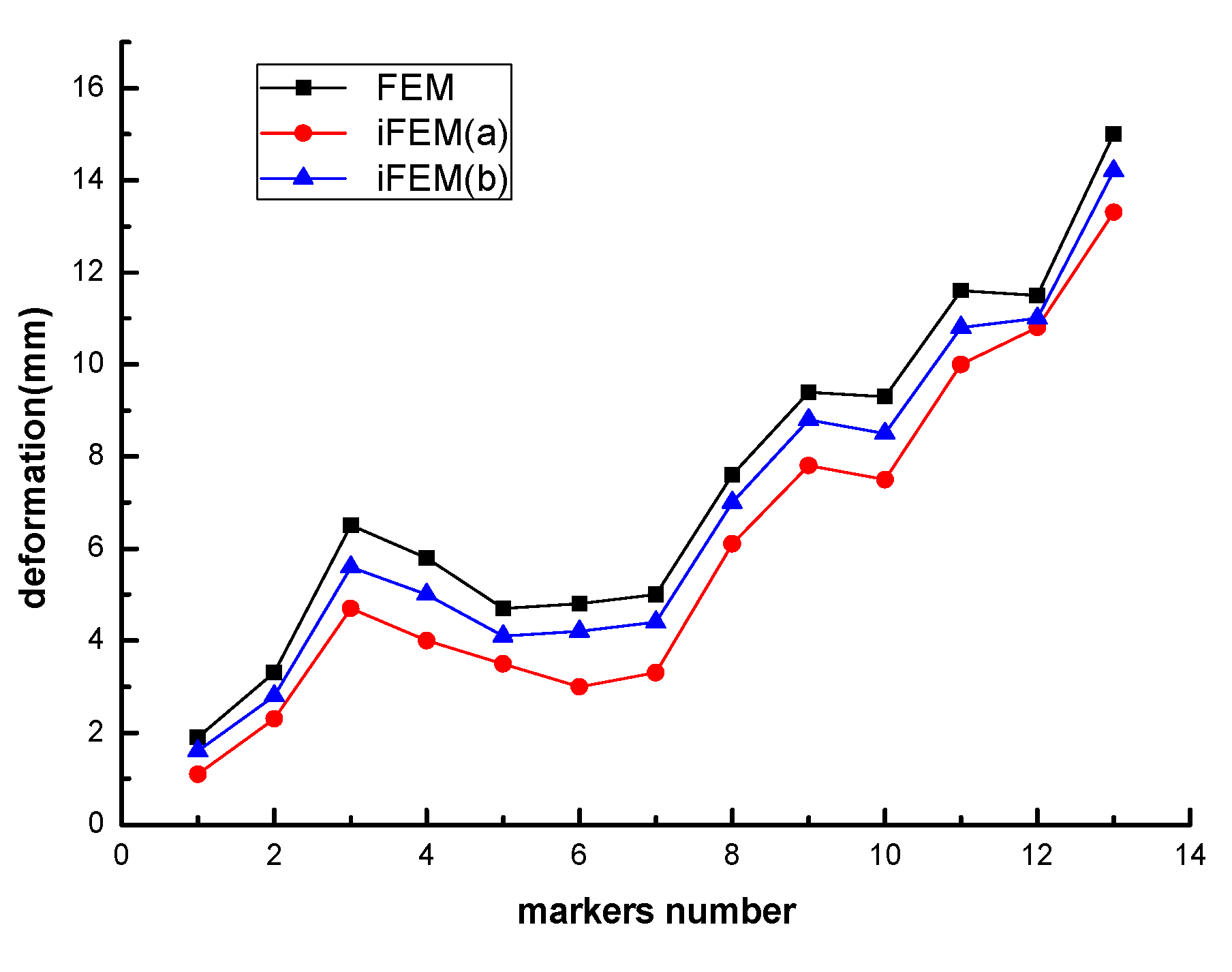
Under the constraint conditions of the cantilever for the test article, the structure subjected to concentrated force is applied in the positive z direction. The inverse element is produced simplistically by these markers defined as element nodes at the edge. The markers number is the same as in Figure 2. The markers’ initial and final position coordinates can be captured by NDI in real time, and the difference of the two sets of coordinates is the deformation of markers. Based on the measured strains and markers’ variation, the results from the iFEM analysis and the NDI measurements are shown as Table 3, and the outline of the whole structure can be viewed in Figure 6.
Table 3 lists the results generated from NDI measurements and iFEM, regarding the former as the benchmark. The maximum deformation of the structure in the Z direction is 19.7 mm. The reconstruction is 1.6 mm, and the RMS of reconstruction accuracy is 1.5 mm. Furthermore, on the basis of the proposed interpolation technology, the RMS value is 0.9 mm, and the reconstruction accuracy increased to 0.6 mm.
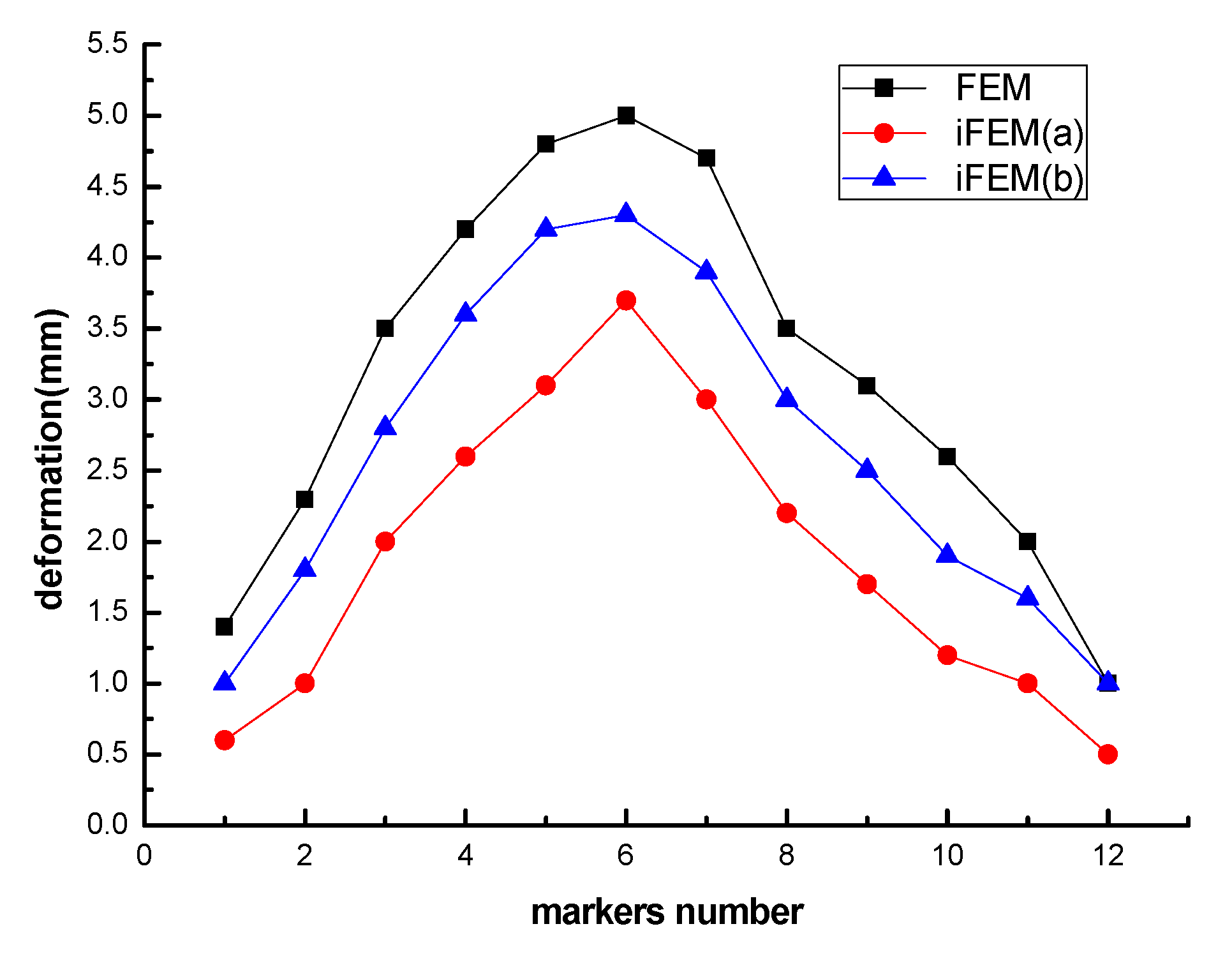
For the case of fixing two edges of structure, the results of markers’ deformation are shown Table 4. In addition, the displacement of the full field can be achieved, as shown in Figure 7.
The results from Table 4 state that the maximum deformation is 5.2 mm. The value of is 1.31 mm, and the RMS is 1.33 mm; otherwise, the RMS calculated by the proposed method is 0.80 mm. Figure 6 and Figure 7 depict the deflection curve of integrated panel in different ways, considering the NDI as an actual value, the curve smoothed by the improved interpolation method is preferable to approximate the real profile.
4. Discussion
Through the analysis of the estimated factors, the values significantly decrease in different degrees based on the proposed method. Meanwhile, the tendency of approaching the practicing deformation also verifies the effectiveness proposed method. Furthermore, the methodology is suitable for practical engineering applications.
5. Conclusions
A multi-node iFEM is presented for the shape sensing of a flexible structure with strain sensors installed at discrete locations. The method is based on the minimization of a weighted-least-squares functional that accounts for the complete set of strain measures consistent with Mindlin plate theory. Otherwise, based on the results from iFEM, adapting the refined interpolation technique to reconstruct the full field deformation again. The approach can have an accurate approximation for big inverse finite elements. Moreover, the method has the advantages of simultaneously achieving extrapolation and interpolation calculation for elements. Then, several case studies were performed and demonstrated the computational efficiency and high accuracy with respect to different forms of the loading structural responses.
The results demonstrated that sufficiently accurate reconstruction can be achieved for the problems considered herein based on a small number of sensors.
Author Contributions
S.N. carried out the majority of work on the paper, verifying measurement scheme, and writing the article. K.L. constructed the finite element model of antenna plate. H.B. proposed this new theory method for shape sensing of antenna plate in real time. J.L. gave advice on the writing of the article. All authors have read and agreed to the published version of the manuscript.
Funding
This research is financially supported by the National Natural Science Foundation of China through Grants 51775401, 51675398, and the CAS “Light of West China” Program 2016-QNXZ-A-7.
Conflicts of Interest
The author declares no conflict of interest.
Appendix A
The matrix in Equations (9) and (10) can be defined as
References
- Kim, S.W.; Kim, E.H.; Rim, M.S.; Shrestha, P.; Lee, I.; Kwon, I.B. Structural Performance Tests of Down Scaled Composite Wind Turbine Blade using Embedded Fiber Bragg Grating Sensors. Int. J. Aeronaut. Space Sci. 2011, 12, 346–353. [Google Scholar] [CrossRef]
- Arnold, E.J.; Yan, J.B.; Hale, R.D.; Rodriguez-Morales, F.; Gogineni, P. Identifying and Compensating for Phase Center Errors in Wing-mounted Phased Arrays for Ice Sheet Sounding. IEEE Trans. Antennas Propag. 2014, 62, 3416–3421. [Google Scholar] [CrossRef]
- Akl, W.; Poh, S.; Baz, A. Wireless and distributed sensing of the shape of morphing structures. Sens. Actuators A Phys. 2007, 140, 94–102. [Google Scholar] [CrossRef]
- Hopkins, M.A.; Truss, J.M.; Lockyer, A.J.; Alt, K.; Kinslow, R.; Kudva, J.N. Smart skin conformal load bearing antenna and other smart structures developments. In Proceedings of the 38th AIAA/ASME/ASCE/AHS/ASC, Structures, Structural Dynamics and Materials Conference, Kissimmee, FL, USA, 7–10 April 1997. [Google Scholar]
- Maniatty, A.; Zabaras, N.; Stelson, K. Finite Element Analysis of Some Inverse Elasticity Problems. J. Eng. Mech. 1989, 115, 1303–1317. [Google Scholar] [CrossRef]
- Maniatty, A.M.; Zabaras, N.J. Investigation of regularization parameters and error estimating in inverse elasticity problems. Int. J. Numer. Methods Eng. 1994, 37, 1039–1052. [Google Scholar] [CrossRef]
- Foss, G.C.; Haugse, E.D. Using Modal Test Results to Develop Strain to Displacement Transformations. In Proceedings of the SPIE—The International Society for Optical Engineering, Philadelphia, PA, USA, 24–25 October 1995; Volume 2460, p. 112. [Google Scholar]
- Bogert, P.B.; Haugse, E.D.; Gehrki, R.E. Structural shape identification from experimental strains using a modal transformation technique. In Proceedings of the 44th AIAA/ASME/ASCE/AHS Structures, Structural Dynamics and Materials Conference, Norfolk, VA, USA, 7–10 April 2003; p. 1626. [Google Scholar]
- Ko, W.L.; Richards, W.L.; Fleischer, V.T. Applications of the Ko Displacement Theory to the Deformed Shape Predictions of the Doubly-tapered Ikhana Wing; NASA Technical Paper NASA/TP-2009-214652; NASA: Edwards, CA, USA, 2009. [Google Scholar]
- Ko, W.L.; Fleischer, V.T. Extension of KOStraight-beam Displacement Theory to Deformed Shape Predictions of Slender Curved Structures; NASA: Edwards, CA, USA, 2011. [Google Scholar]
- Jutte, C.V.; Ko, W.L.; Stephens, C.A.; Bakalyar, J.A.; Richards, W.L. Deformed Shape Calculation of a Full-Scale Wing Using Fiber Optic Strain Data from a Ground Loads Test; Rept, TP-215975; NASA Langley Research Center: Hampton, VA, USA, 2011. [Google Scholar]
- Tessler, A.; Spangler, J.L. A Variational Principal for Reconstruction of Elastic Deformation of Shear Deformable Plates and Shells; NASA TM-2003-192445; NASA: Edwards, CA, USA, 2003. [Google Scholar]
- Tessler, A.; Spangler, J.L. Inverse FEM for full-field reconstruction of elastic deformations in shear deformable plates and shells. In Proceedings of the 2nd European Workshop on Structural Health Monitoring, Munich, Germany, 7–9 July 2004. [Google Scholar]
- Tessler, A.; Roy, R.; Esposito, M.; Surace, C.; Gherlone, M. Shape Sensing of Plate and Shell Structures Undergoing Large Displacements Using the Inverse Finite Element Method. Shock. Vib. 2018, 2018, 1–8. [Google Scholar] [CrossRef]
- Gherlone, M. Beam Inverse Finite Element Formulation; LAQ Report; Politecnico di Torino: Turin, Italy, 2008. [Google Scholar]
- Gherlone, M.; Cerracchio, P.; Mattone, M.; di Sciuva, M.; Tessler, A. Beam shape sensing using inverse Finite Element Method: Theory and experimental validation. In Proceedings of the 8th International Workshop on Structural Health Monitoring, Stanford, CA, USA, 13–15 September 2011. [Google Scholar]
- Gherlone, M.; Cerracchio, P.; Mattone, M.; Di Sciuva, M.; Tessler, A. An inverse finite element method for beam shape sensing: Theoretical framework and experimental validation. Smart Mater. Struct. 2014, 23, 045027. [Google Scholar] [CrossRef] [Green Version]
- Gherlone, M.; Cerracchio, P.; Mattone, M.; Di Sciuva, M.; Tessler, A. Dynamic shape reconstruction of three-dimensional frame structures using the inverse finite element method. In Proceedings of the 3rd ECCOMAS Thematic Conference on Computational Methods in Structural Dynamics and Earthquake Engineering, Island of Corfu, Greece, 26–28 May 2011. [Google Scholar]
- Gherlone, M.; Cerracchio, P.; Mattone, M.; Di Sciuva, M.; Tessler, A. Shape sensing of 3D frame structures using an inverse Finite Element Method. Int. J. Solids Struct. 2012, 49, 3100–3112. [Google Scholar] [CrossRef] [Green Version]
- Tessler, A.; Hughes, T.J.R. A three-node mindlin plate element with improved transverse shear. Comput. Methods Appl. Mech. Eng. 2012, 50, 71–101. [Google Scholar] [CrossRef]
- Kefal, A.; Oterkus, E.; Tessler, A.; Spangler, J.L. A quadrilateral inverse-shell element with drilling degrees of freedom for shape sensing and structural health monitoring. Eng. Sci. Technol. Int. J. 2016, 19, 1299–1313. [Google Scholar] [CrossRef] [Green Version]
- Cerracchio, P.; Gherlone, M.; di Sciuva, M.; Tessler, A. Shape and stress sensing of multilayered composite and sandwich structures using an inverse finite element method. In Proceedings of the 5th International Conference on Computational Methods for Coupled Problems in Science and Engineering, Ibiza, Spain, 17–19 June 2013. [Google Scholar]
- Kefal, A.; Tessler, A.; Oterkus, E. An enhanced inverse Finite element method for displacement and stress monitoring of multilayered composite and sandwich structures. Compos. Struct. 2017, 179, 514–540. [Google Scholar] [CrossRef] [Green Version]
- Barber, J.R. Computational Elasticity: Theory of Elasticity, Finite and Boundary Element Methods; Alpha Science Int’l Ltd.: Oxford, UK, 2008. [Google Scholar]
- Baitsch, M.; Hartmann, D. Piecewise polynomial shape functions for hp-finite element methods. Comput. Meth. Appl. Mech. Eng. 2009, 198, 1126–1137. [Google Scholar] [CrossRef]
- Shi, J.; Zheng, K.; Tan, Y.; Yang, K.; Zhou, G. Response simulating interpolation methods for expanding experimental data based on numerical shape functions. Comput. Struct. 2019, 218, 1–8. [Google Scholar] [CrossRef]
Figure 1.
Plate model notion.

Figure 2.
Inverse finite elements model of structure.

Figure 3.
Deformation of the plate structure.

Figure 4.
Deformation of the plate structure.

Figure 5.
The measurement system; (a) fixed device; (b) Fiber Bragg Grating (FBG) demodulator; (c) Northern Digital Incorporation (NDI); (d) marker; (e) Measurement process.
Figure 5.
The measurement system; (a) fixed device; (b) Fiber Bragg Grating (FBG) demodulator; (c) Northern Digital Incorporation (NDI); (d) marker; (e) Measurement process.

Figure 6.
The deformation of the plate structure.

Figure 7.
Deformation of plate structure.


Table 1.
Results of nodes deformation.
| Node | Z Directional Deformation (mm) | ||
|---|---|---|---|
| FEM | iFEM | Error | |
| 3 | 11.3 | 11.1 | 0.2 |
| 4 | 11.3 | 11.0 | 0.3 |
| 5 | 5.4 | 5.60 | 0.2 |
| 6 | 50.1 | 48.1 | 2.1 |
| 7 | 50.1 | 50.0 | 0.1 |
| 8 | 29.3 | 26.6 | 2.8 |
Table 2.
Results of the nodes deformation.
| Node | Z Directional Deformation (mm) | ||
|---|---|---|---|
| Fem | iFEM | Error | |
| 3 | 2.27 | 2.01 | 0.26 |
| 4 | 2.49 | 2.11 | 0.38 |
| 5 | 1.31 | 1.10 | 0.15 |
| 8 | 1.83 | 1.35 | 0.48 |
Table 3.
The results of markers deformation.
| Marker | Z Directional Deformation (mm) | ||
|---|---|---|---|
| NDI | iFEM | Error | |
| 3 | 6.71 | 6.00 | 0.71 |
| 4 | 6.92 | 6.16 | 0.76 |
| 5 | 2.70 | 1.85 | 0.85 |
| 6 | 19.6 | 16.9 | 2.70 |
| 7 | 19.7 | 17.0 | 2.70 |
| 8 | 12.5 | 11.6 | 0.90 |
Table 4.
The results of the markers deformation.
| Marker | Z Directional Deformation (mm) | ||
|---|---|---|---|
| NDI | iFEM | Error | |
| 3 | 5.22 | 4.98 | 0.24 |
| 4 | 4.86 | 4.10 | 0.76 |
| 5 | 1.58 | 1.06 | 0.52 |
| 6 | 1.43 | 1.00 | 0.43 |
Publisher’s Note: MDPI stays neutral with regard to jurisdictional claims in published maps and institutional affiliations. |
© 2020 by the authors. Licensee MDPI, Basel, Switzerland. This article is an open access article distributed under the terms and conditions of the Creative Commons Attribution (CC BY) license (http://creativecommons.org/licenses/by/4.0/).
Share and Cite
MDPI and ACS Style
Niu, S.; Li, K.; Liu, J.; Bao, H. A Refined Shape Sensing Method for Skin Antenna Structure Based on Inverse Finite Element Method. Appl. Sci. 2020, 10, 7620. https://0-doi-org.brum.beds.ac.uk/10.3390/app10217620
AMA Style
Niu S, Li K, Liu J, Bao H. A Refined Shape Sensing Method for Skin Antenna Structure Based on Inverse Finite Element Method. Applied Sciences. 2020; 10(21):7620. https://0-doi-org.brum.beds.ac.uk/10.3390/app10217620
Chicago/Turabian StyleNiu, Shengtao, Kexiang Li, Jianfeng Liu, and Hong Bao. 2020. "A Refined Shape Sensing Method for Skin Antenna Structure Based on Inverse Finite Element Method" Applied Sciences 10, no. 21: 7620. https://0-doi-org.brum.beds.ac.uk/10.3390/app10217620
Note that from the first issue of 2016, this journal uses article numbers instead of page numbers. See further details here.