Influence of Powder and Liquid Multi-Wall Carbon Nanotubes on Hydration and Dispersion of the Cementitious Composites


1
Department of Architectural Engineering, Korea National University of Transportation, Chungju, Chungbuk 27469, Korea
2
Department of Safety Engineering, Korea National University of Transportation, Chungju, Chungbuk 27469, Korea
*
Author to whom correspondence should be addressed.
Appl. Sci. 2020, 10(21), 7948; https://0-doi-org.brum.beds.ac.uk/10.3390/app10217948
Submission received: 12 October 2020
/
Revised: 2 November 2020
/
Accepted: 7 November 2020
/
Published: 9 November 2020
(This article belongs to the Special Issue Multifunctional Cement Composites for Structural Health Monitoring)
Abstract
:Two types of multi-walled carbon nanotubes (MWCNTs), powder and liquid, were added to cementitious composites to build self-sensing concrete. To properly evaluate and quantify the effect of MWCNTs on electrical resistance, various tests, including isothermal conduction calorimetry, were carried out. One of primary issues of self-monitoring concrete is dispersion, so ultrasonication was used to properly mix the CNTs in the dispersion solution, and silica fume was employed to make the specimens. Scanning electron microscopy (SEM), Raman spectroscopy, and porosity analyses were performed to investigate the physical properties of the composites and to confirm uniform dispersion. The distance of the electrical resistance was also measured, and the dosages and types of MWCNTs were analyzed.
1. Introduction
Concrete is being employed to build engineering infrastructure, causing energy and environmental issues (e.g., carbon dioxide emissions). However, compared with other materials in the construction industry such as steel, metal, and even polymers, it is better than others in terms of energy consumption and environmental problems. This is a primary reason why concrete is used for most infrastructures. The increasing demand of health-monitoring concrete is a critical global challenge of twenty-first century. In the early 1990s, many researchers and scholars experimented with self-sensing concrete by mixing functional fillers with concrete composites, including carbon fiber, graphite powder, steel slag, carbon nanotubes, carbon blocks, or a hybrid of multiple fillers [1,2,3,4,5,6,7,8,9,10,11,12,13,14,15,16,17,18].
The carbon nanotube (CNT) has been utilized in a variety of industrial fields due to its outstanding mechanical properties, high thermal conductivity, low unit mass, and exceptional corrosion resistance. In the field of construction, CNTs have been added in concrete composites to create smart materials (called self-monitoring concrete) due to their excellent electrical conductivity. In general, the CNT exhibits a considerably low density of 1.3–1.4 g/cm3 and, when added to cement concrete mixtures, the amount of CNTs does not exceed a binder weight of 2.0%. In addition, the effective dispersion of CNTs in the composites is very difficult to obtain due to van der Waals forces acting between the CNT particles. If CNTs are not properly dispersed, they are also known to limit improvements in the mechanical properties of cement composites. In order to ensure homogeneous dispersion in cement composites, there are various techniques to apply, such as ultrasonication, silica fume, admixtures, surface modification of CNTs, and minimizing the water-to-binder ratio. An ultrasonic disperser was used as the most common tool [19]. The vibration caused by the ultrasonic device resulted in high local shear on the end of CNTs and an increase in pores between particles, and it then achieved the proper dispersion of CNTs [20,21]. Makar et al. [22] demonstrated that the use of ethanol in combination with ultrasonic treatment techniques was effective for CNT dispersion. However, the CNT dispersion solution prepared using ethanol was not suitable because it delayed condensation and hydration when added to the cement composite. Konsta-Gdoutos et al. [23] carried out experimental studies on the dispersion of CNT in cement mixtures by using both surfactants and ultrasonication, and they concluded that ultrasonic energy of 70 Pa was necessary for homogenous dispersion. Sanchez and Ince [24] found that the proper use of silica fumes as a dispersion agent was effective at dispersing CNTs in cement composites. Luo et al. [25] conducted experiments on pastes using cement, silica fumes, carbon nanotube powders, and a CNT dispersion solution prepared using surfactants, and they revealed that the use of surfactants contributed to improving the compressive and flexural strengths. Kim et al. [26] used scanning electron microscopy (SEM) analysis to investigate the dispersion of CNT-embedded cementitious composites with silica fume, and they demonstrated that the spherical shape of silica fume was still found in the composites after hydration, the CNT agglomeration spaces were filled with it, and size reduction of the agglomeration eventually occurred. Collins et al. [27] conducted an experimental study on cementitious mixtures with CNTs added, with admixtures including air entrainment, styrene butadiene rubber, polycarboxylates, calcium naphthalene sulfonate, and lignosulfonate, to investigate the dispersion of CNTs in composites. Ha and Kang [28] found that it was best to use polycarboxylic, acid-based, high-performance water-reducing agents for CNT dispersion. Li et al. [29] investigated the mechanical response of cement composites added with modified, multi-walled carbon nanotubes (MWCNTs). H2SO4 and HNO3 had been used treat the surface of the CNTs, which had higher dispersion characteristics in cement mixtures. Cwirzen et al. [30] concluded from their experimental investigation that the CNTs modified by a polyacrylic polymer in an aqueous solution was suitably dispersed in more than two months. Nochaiya and Chaipanich [31] performed mercury intrusion porosimetry and scanning electron microscopy in order to investigate the behavior of MWCNTs, in terms of porosity and microstructures, and found that the water-to-binder ratio influenced the dispersion degree in cementitious composites. In spite of these numerous publications and studies, there are few works on the effect of MWCNT types on the electrical resistance of cementitious composites. In particular, to the best of the authors’ knowledge, there is no publication related to composites of up to 2% MWCNTs. Therefore, a comprehensive investigation of cementitious composites containing 2% MWCNT types (powder and liquid) needs to be studied.
In this study, in order to investigate the effects of MWCNT types (powder and liquid types) in composites, several experiments were conducted. To understand the heat of hydration released in the paste containing MWCNTs, isothermal conduction calorimetry was employed. The compressive strengths of the composites were measured. Analyses of porosity, Raman spectrometry, and SEM were carried out to investigate the homogenous dispersion of MWCNTs in cementitious composites. Finally, the electrical properties of MWCNTs embedded in cementitious composites were analyzed from the experimental data.
2. Experimental Programs
2.1. Materials and Mixture Proportions
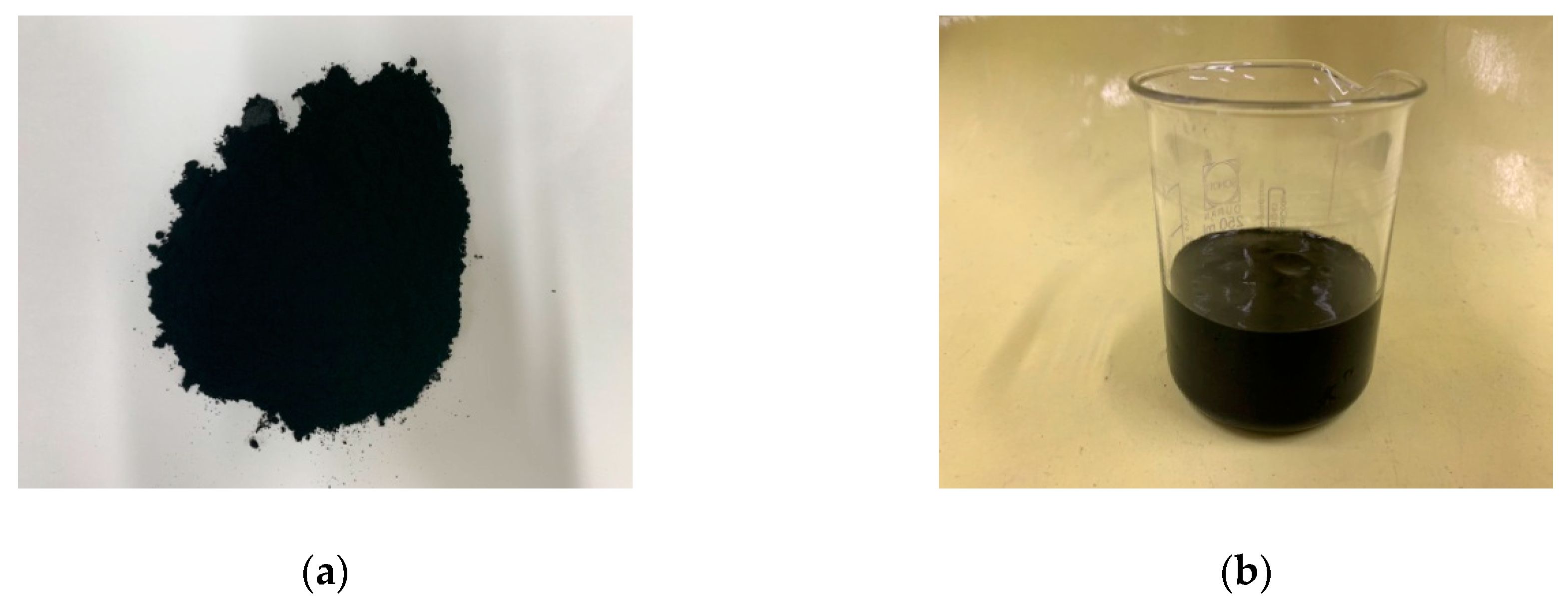
Ordinary Portland Cement (OPC, Type I KS L 5201 [32]) and silica fume were employed, and their chemical compositions and densities are summarized in Table 1. Two types of MWCNTs (powder and liquid) were considered, as presented in Figure 1. Table 2 and Table 3 show the composition of the liquid type (mass fraction) and the physical properties of the MWCNTs, respectively. Ultrasonic waves with a frequency of 20,000 kHz were used for an hour to ensure the proper dispersion of CNTs in the solution. The water-to-binder ratio (w/b) was set as 20%, and the polycarboxylate-based, high-performance, water-reducing agent (KS F 2560 [33], Chemical Admixtures) was added to the cementitious composites. Detailed information on the mixture proportions used in all tests is demonstrated in Table 4.
2.2. Experimental Methods
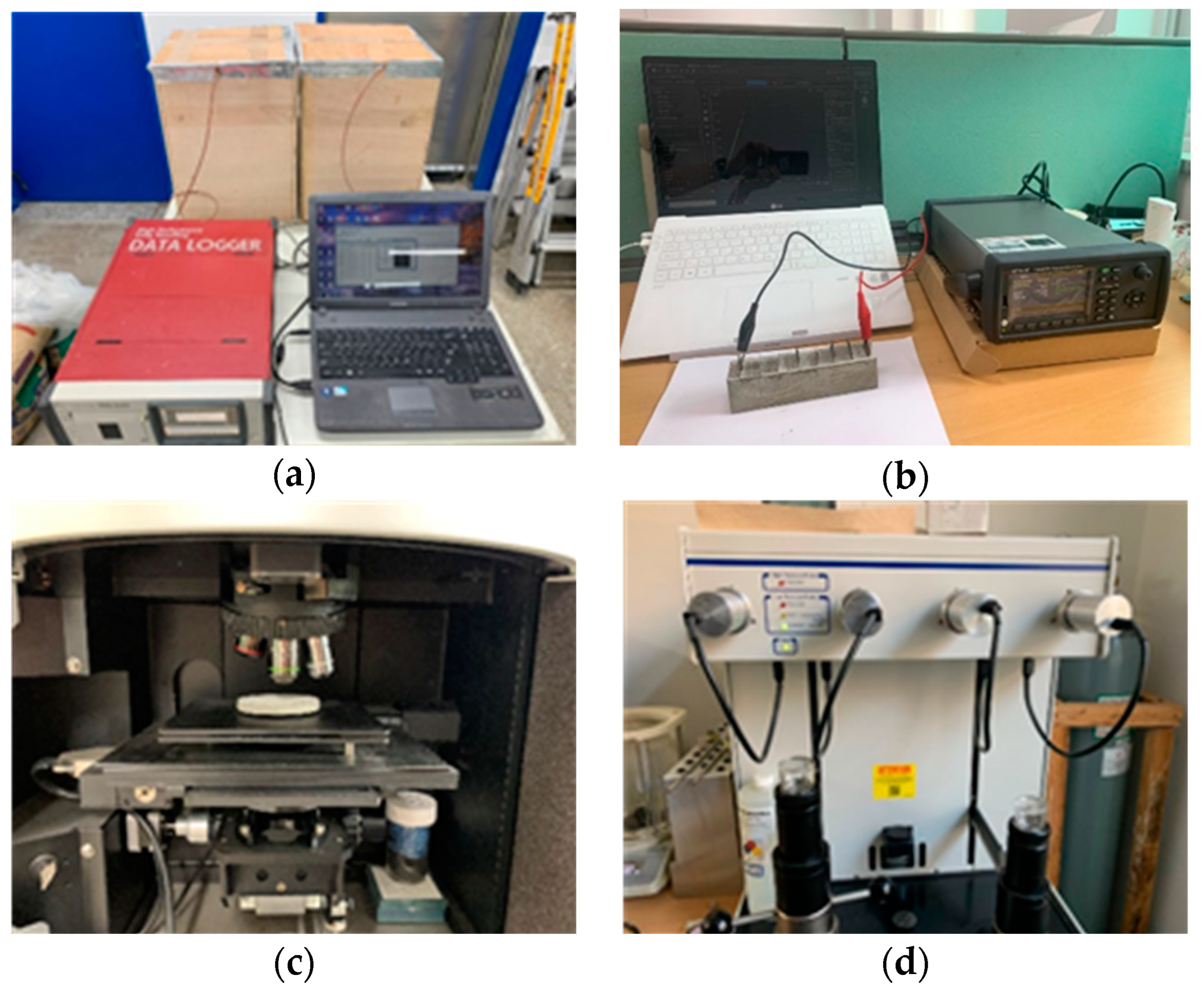
Figure 2 displays the experimental equipment. To measure the heat of hydration, a cylindrical specimen with a diameter of 100 mm and a height of 200 mm was fabricated, and a thermocouple was then embedded. It was stored in an insulated cuboid box with dimensions of 300 × 300 × 400 mm3, and the heat of hydration was recorded for 72 h at one-minute intervals.
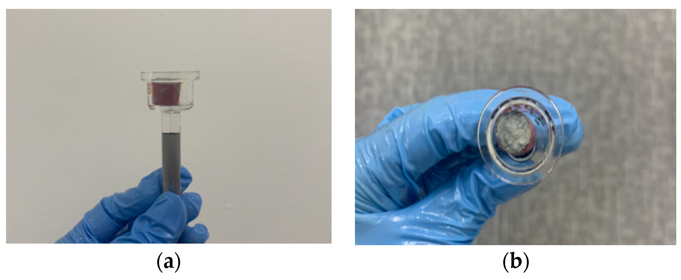
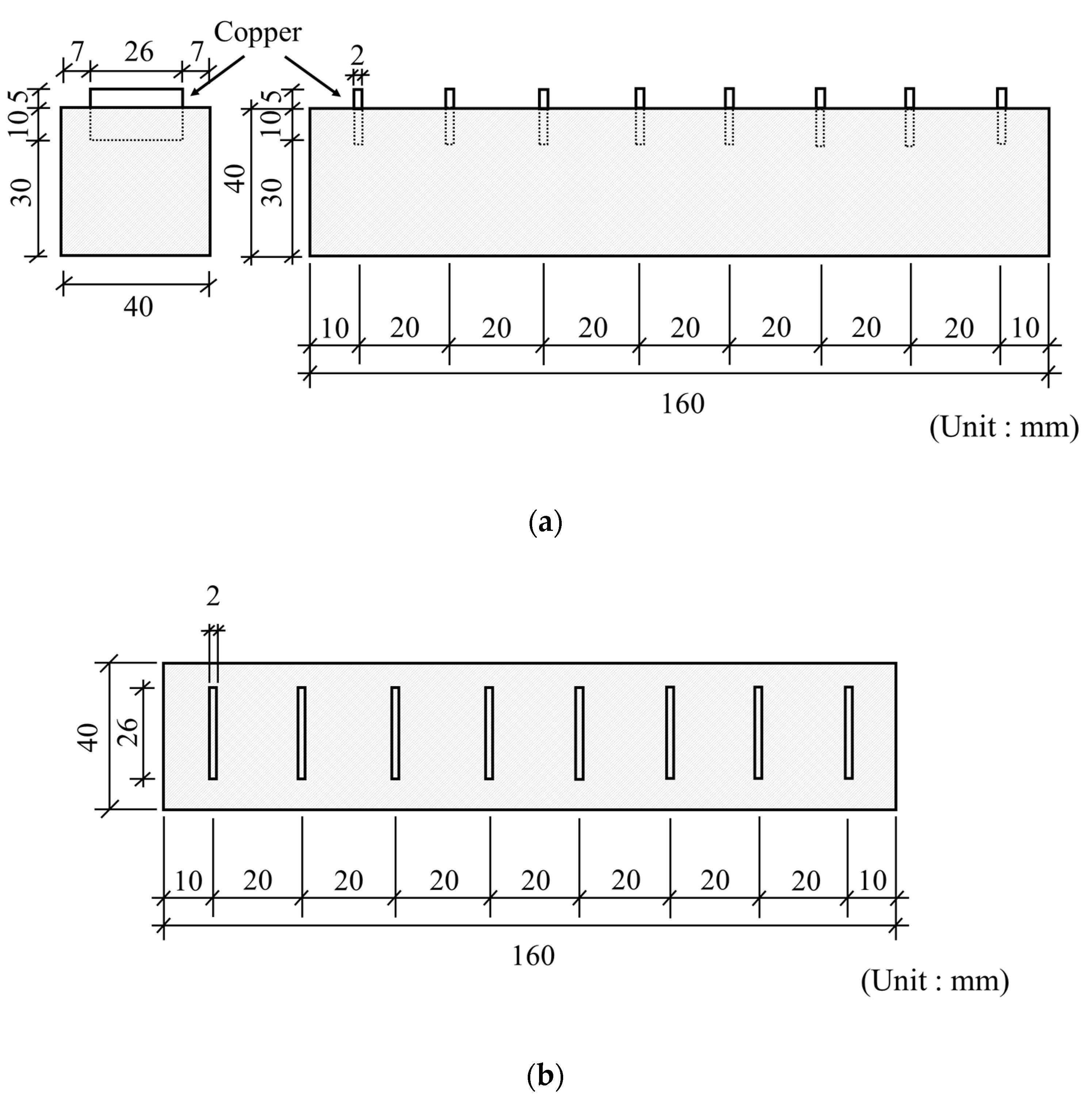
Isothermal conduction calorimetry analysis was conducted to measure the rate of heat evolution of the cement paste for 36 h. The compressive strength of the cementitious composites was measured as per KS L ISO 679 [34] at 3, 7, 14, and 28 days. After finishing the measurements of the compressive strength tests at the age of 28 days, SEM analysis was performed with a sample collected from the specimen tested. For SEM analysis, the sample was dried at 50 °C for four hours, and the specimen was kept in a vacuum state for two hours before the test. For Raman spectroscopy analysis, a cylindrical specimen with a diameter of 70 mm and height of 10 mm was fabricated, and a Raman spectrometer (NRS-3200) was used. In order to measure the pore sizes of the composites, the method of mercury intrusion porosimetry was employed, and a sample at the age of 28 days and dried for four hours at 50 °C was employed by using the Autopore 9600IV (measurement range of 0.003–900 μm), presented in Figure 2d. The cylindrical specimen for the porosity test was 10 mm in diameter and 10 mm in height (see Figure 3). Figure 4 demonstrates the schematic of the cementitious materials for the measurement of electrical resistance. Copper plates were installed at 20 mm intervals to investigate the effect of distance. Specimens were demolded 24 h after casting. After demolding, all specimens were curried as per KS L ISO 679 [34] at a room temperature of 20 ± 1 °C and a relative humidity of 60%. Moreover, SEM and Raman spectroscopy were conducted to investigate the physical properties of the composites.
3. Experimental Results and Discussion
3.1. Heat of Hydration
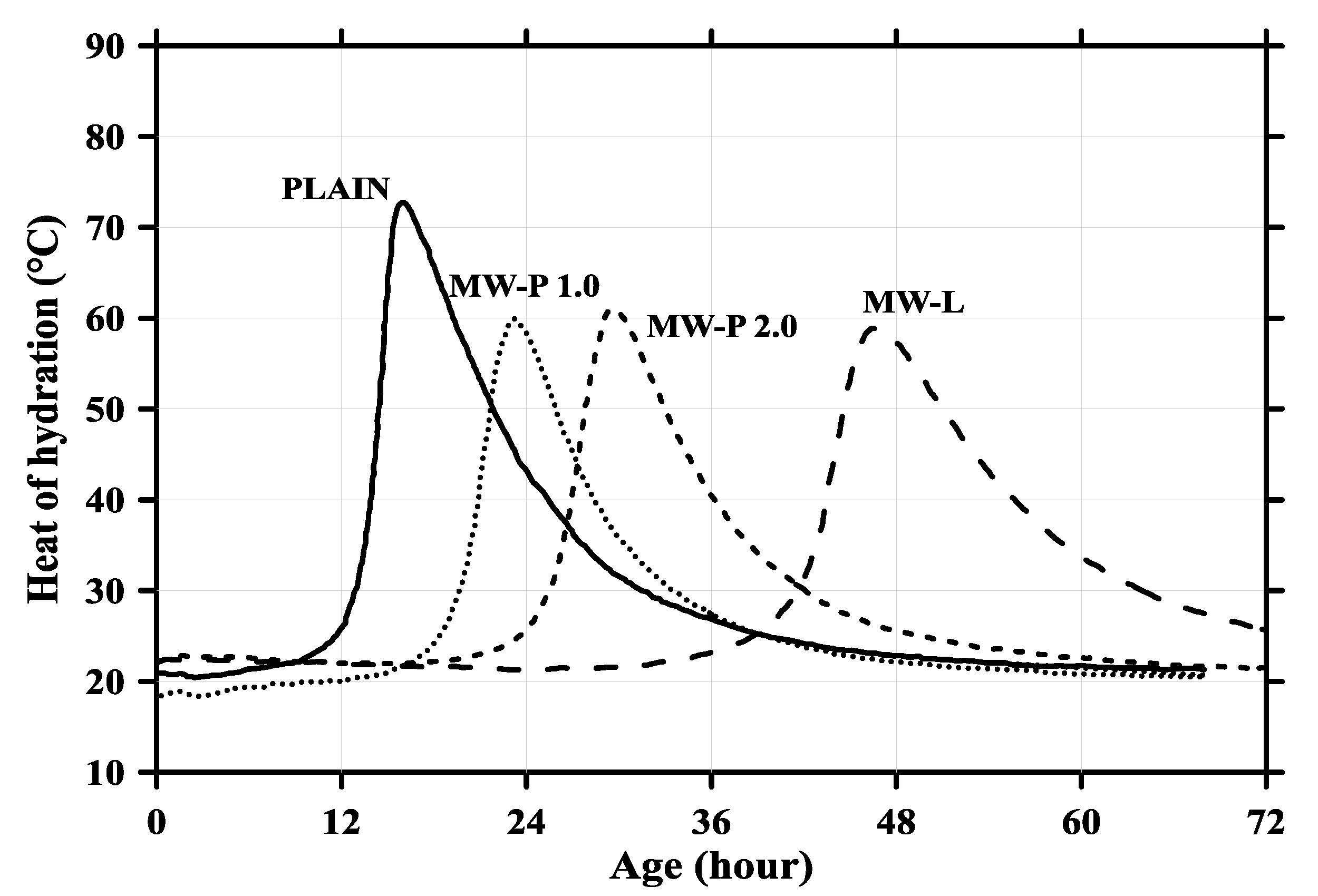
Figure 5 presents the heat of hydration curve. Since the MWCNTs were added, regardless of whether they were powder or liquid, it was observed that the heat of the hydration decreased by approximately 10 °C to 14 °C compared with the plain cement paste. In Figure 4, MW-P1.0, MW-P2.0, and MW-L signify the powder MWCNTs, with a 1.0% mass fraction of cement and silica fume for the powder MWCNTs and a 2.0% mass fraction of cement and silica fume for the liquid MWCNTs, respectively. The primary reason for the rapid shift of the heat of hydration to the right was the high thermal conductivity of the MWCNTs. In addition, the maximum values of the heat of hydration for the plain, MW-P1.0, MW-P 2.0, and MW-L MWCNTs were measured at 14, 30, 46, and 26 h, respectively. This is not due to the direct impact of the MWCNTs, but because of condensation delay, as the amount of the chemical admixture was excessively added at 5–12%.
3.2. Heat Flow
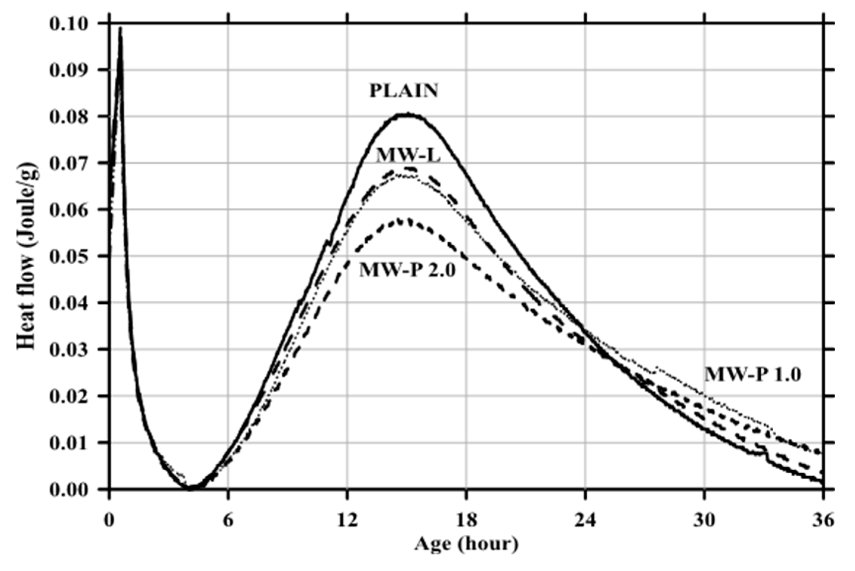
Figure 6 describes the heat flow as a function of age for four different composites. In general, as the MWCNTs were added, the cumulative heat of the composites tended to decrease slightly compared with the plain cement paste. The cumulative heat decreased with the increasing amount of powder MWCNTs because the heat generated during hydration was released by the MWCNTs. However, the reduced heat was approximately 4~12 Joule/g, denoting no significant difference, and there was no effect of the MWCNTs on the strength due to their chemical reactions in the composites.
3.3. Compressive Strength
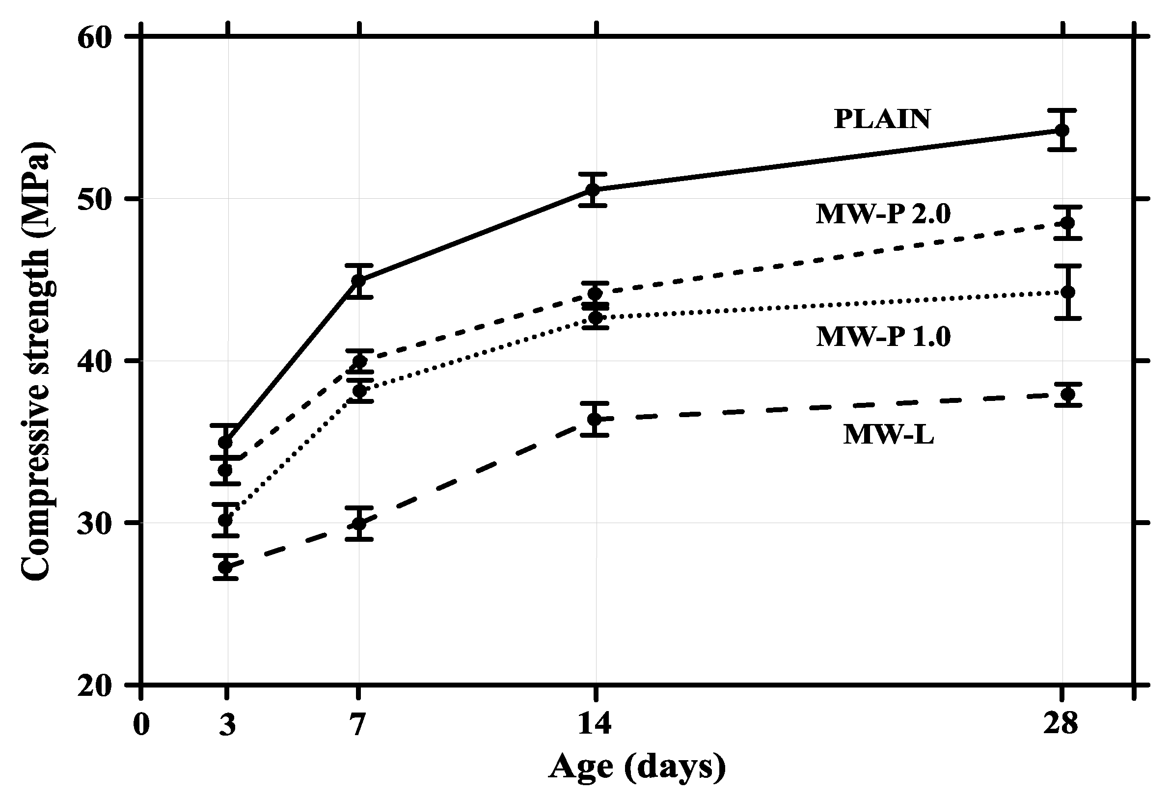
The compressive strengths of four different composites are shown in Figure 7. Similar to the findings of previous research conducted by Oh et al. [35,36], the decreasing trend of compressive strength was exhibited as the MWCNTs were added, and the strength further decreased as the addition ratio increased. The compressive strength decreased by 10 to 16 MPa, compared with the plain cement paste at 28 days. The chemical reaction of the MWCNTs did not occur in the cement composite as it did in the heat flow results because the decrease in compressive strength resulted from the intorsion and agglomeration of the MWCNTs, caused by the van der Waals forces in the cement composite. It was suggested that if the nano-sized MWCNTs do not achieve homogeneous dispersion, they cannot lead to densification due to the micro-filler effect in the cement composite. However, the MW-L case was relatively dispersive compared with MW-P1.0 or MW-P2.0, so the decrease in strength of the liquid type was not greater than the powder type.
3.4. Porosity
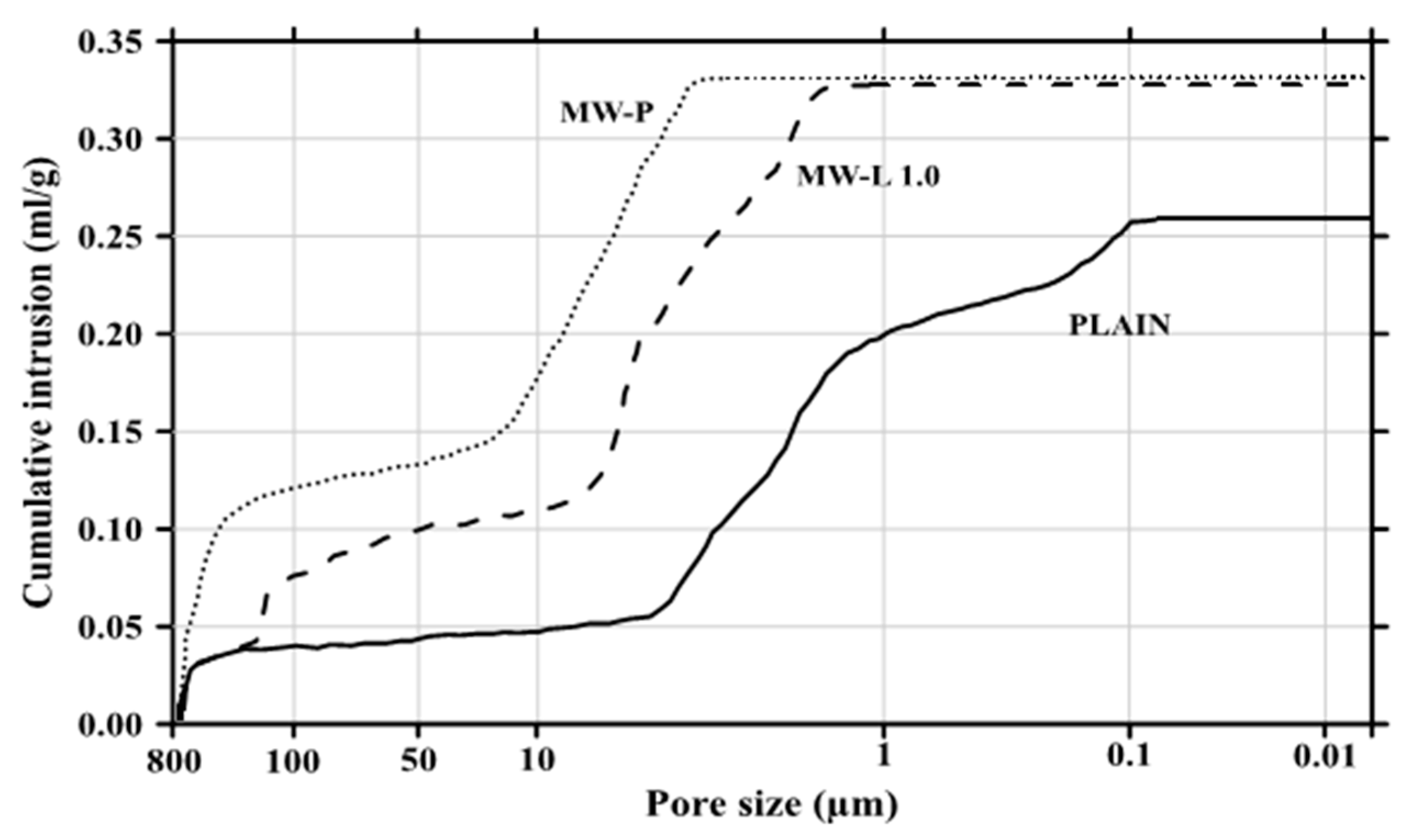
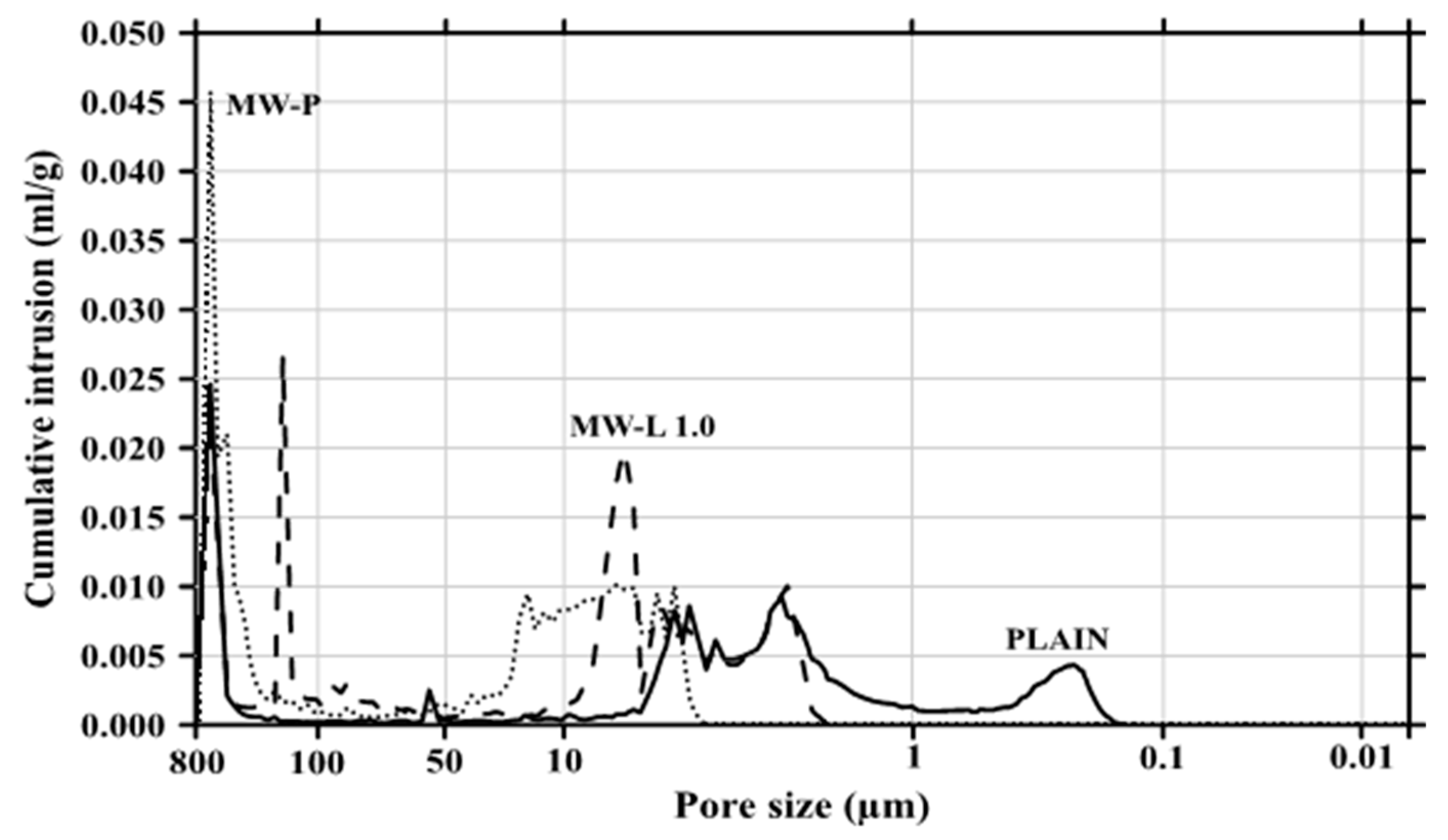
Figure 8 and Figure 9 show the cumulative pore volume and pore size distribution, respectively, measured by mercury intrusion porosimetry. In Figure 8, the pore volume in the cement composites increased with the addition of MWCNTs. In theory [35,36], MWCNTs in the size range of 5–100 nm reduced the pore volume due to the filling effect of the composites. However, if homogeneous dispersion was not achieved, the pore volume increased. In particular, the pore size distribution in Figure 9 revealed that the amount of relatively large micro-pores increased with the MWCNTs, while that of small micro-pores decreased as the MWCNTs were added. This implies that the intorsion and agglomeration of the MWCNTs occurred due to van der Waals forces, and thus the compressive strength of the cement composite incorporating the MWCNTs decreased as large micro-pores appeared.
3.5. Raman Spectroscopy
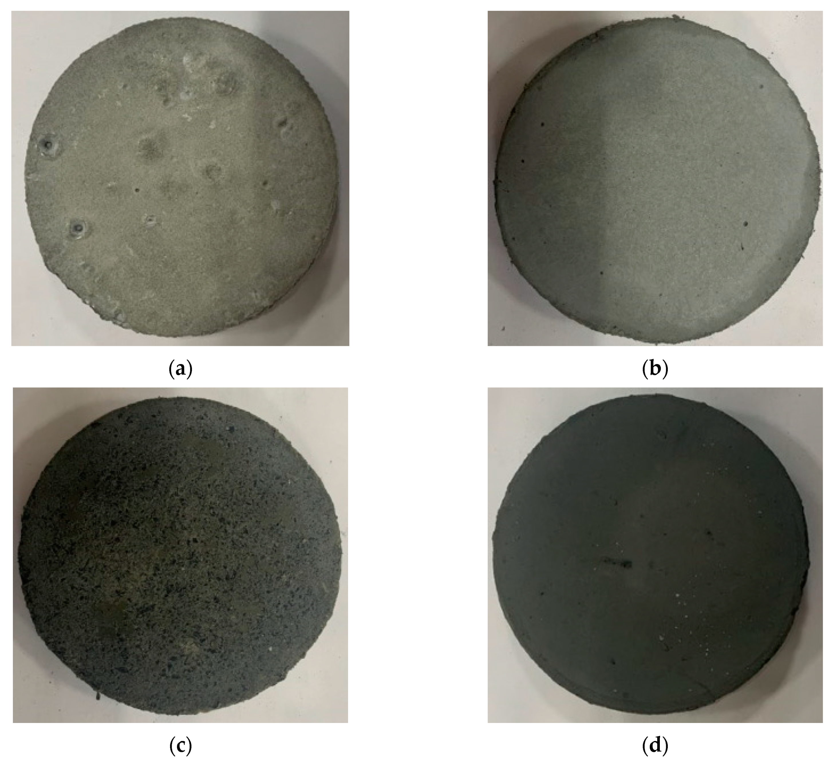
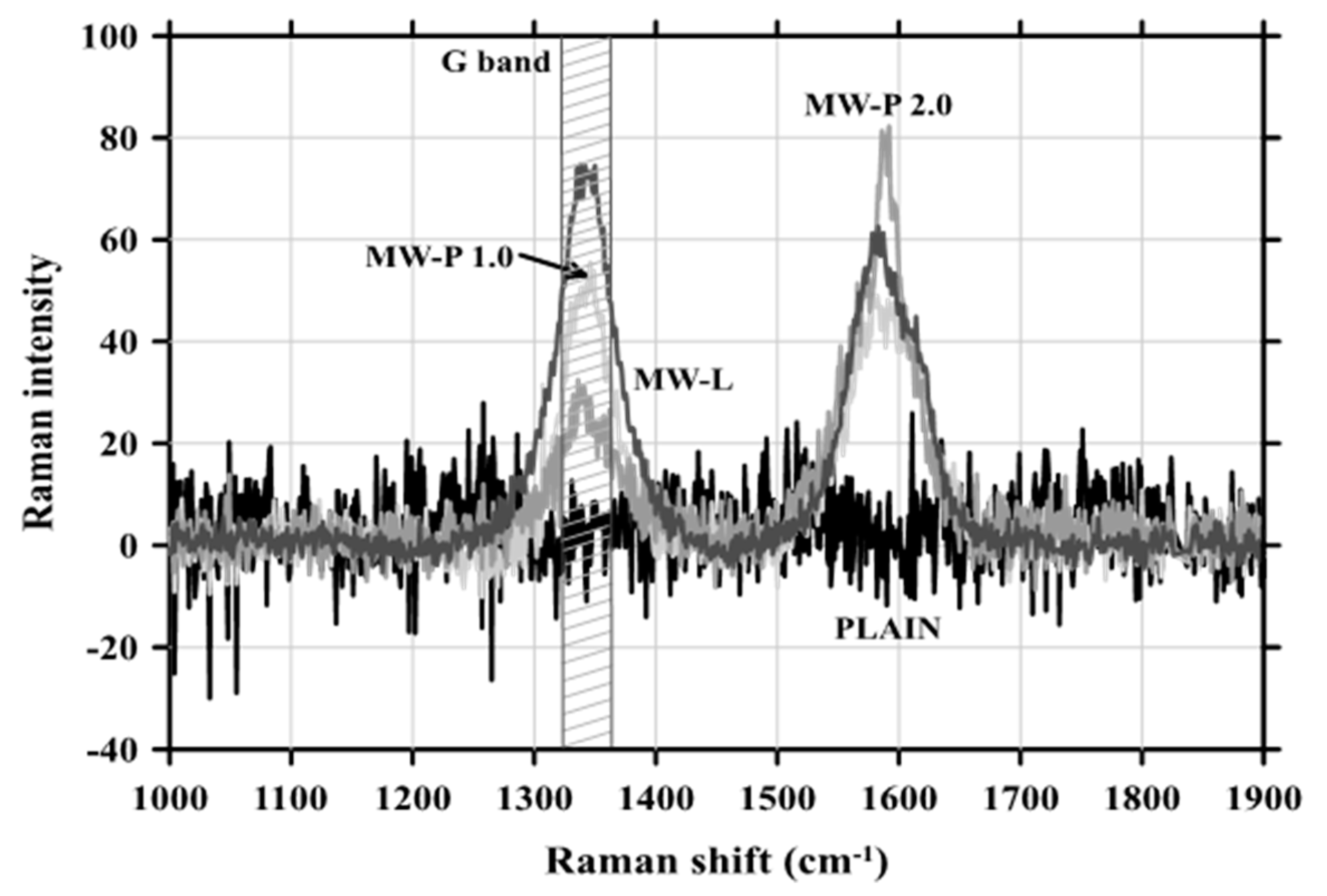
Figure 10 shows the Raman spectroscopy specimens, and the results of the spectrum analysis using the Raman spectrometer are provided in Figure 11. The MWCNT-added specimen exhibited a peak at 1350 cm−1, which was the same as in the graphite spectrum (called G band, with a range of 1330–1360 cm−1) [37]. The intensity of the spectrum was the highest (about 78) in the MW-L MWCNTs, indicating that relatively homogeneous dispersion was achieved in the cement composite, compared with the powder MWCNTs.
3.6. SEM Analysis
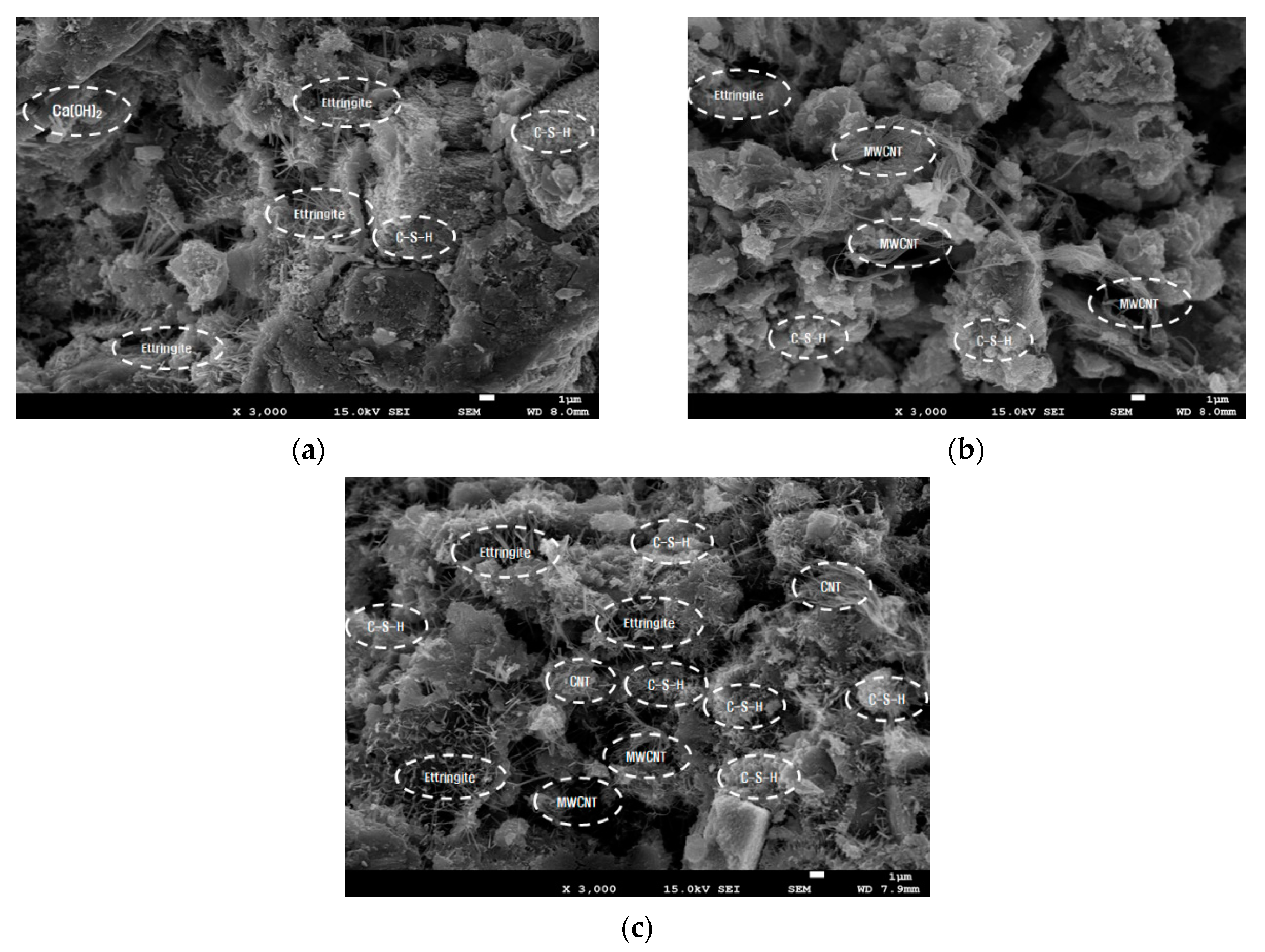
Figure 12 presents the SEM images of the MWCNT composites. In the powder type specimen, it was obviously observed that the intorsion and agglomeration of MWCNTs took place because of van der Waals forces. In MW-P 1.0, MWCNTs were not found in the SEM image due to agglomeration, while intorsion and agglomeration, like a ball of thread, was clearly identified in the SEM image of MW-P 2.0. However, in the MW-L type, there was the small amount of MWCNT agglomeration, which was relatively dispersed within the structure. This indicates that the liquid MWCNTs can ensure better dispersibility in cement composites than the powder type.
3.7. Electric Resistance
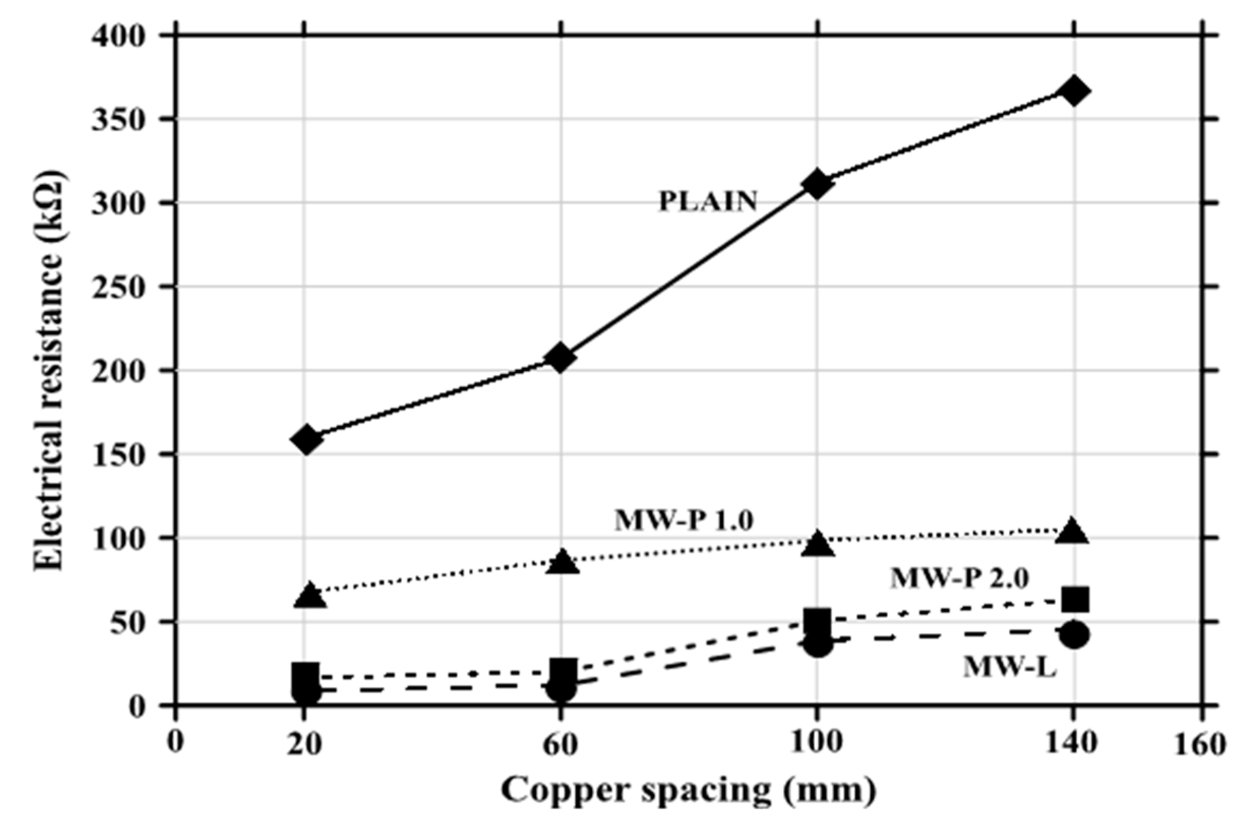
The electrical resistance values, according to the measurement distance, are demonstrated in Figure 13. It was found that (1) as the addition ratio of the MWCNTs increased, the electrical resistance value decreased, and (2) the shorter the measurement distance, the smaller the electrical resistance value. Even though MWCNT agglomeration occurred in the cement composites, it spread throughout the entire structure, reducing the electrical resistance value. Furthermore, the electrical resistance decreased even in the liquid state specimen, denoting relatively good dispersion. This finding implies that the MWCNT-added cement composite exhibits electrical conductivity, regardless of homogeneous dispersion.
4. Conclusions
From the investigation of the effects of MWCNT properties on dispersion in cementitious composites, the following findings and conclusions were obtained:
- The heat of hydration decreased with an increase in the addition ratio of the MWCNTs because retardation occurred, due to an excessive amount of the chemical admixture. In addition, as the amount of MWCNTs increased, the amount of the chemical admixture increased, because the powder volume increased in the specimen. On the other hand, the liquid MWCNT showed further improvement in workability compared with the powder MWCNT, thus reducing the amount of the chemical admixture, and the hydration delay was not as great as that in the powder MWCNT.
- The heat flow decreased slightly with the addition of MWCNTs, but the degree of the decrease was not significant. The MWCNTs exhibited no chemical reactions in the composites. Therefore, it was concluded that the decrease in the mechanical performance of the cementitious composite was not due to the chemical reaction, but due to the physical properties. In particular, it was due to the MWCNT agglomeration caused by van der Waals forces.
- The compressive strength tended to decrease as MWCNTs were added. In particular, the powder type showed a greater reduction than the liquid type, and it was found that the MWCNTs did not obtain the micro-filler effect in the mixtures, but rather acted as a strength reduction factor.
- The porosity analysis indicated that the porosity increased as MWCNTs were added, because the MWCNT agglomeration occurred due to failure to secure uniform dispersion in the cementitious composite. Thus, it existed in the form of large capillary pores, which resulted in an increase in the porosity, leading to a decrease in compressive strength. However, when the liquid MWCNT was added, the porosity further decreased compared with the powder type, which implies that the liquid type was advantageous in terms of dispersibility.
- Through Raman spectroscopy analysis, it was revealed that the MWCNTs showed G bands (1350 cm−1) in their Raman spectra of graphite. This confirmed the presence or absence of MWCNTs in the composite, and the strength of the peak was highest in the liquid type of MWCNTs, presenting more homogeneous dispersion than the powder MWCNT.
- In the SEM analysis, agglomeration was clearly observed in the powder MWCNT, and the form of a skein of thread existed. It failed to disperse as it separated from the hydrates in the composite, which resulted in a decrease in strength, due to the presence of pores. However, the liquid MWCNT was relatively well dispersed in the overall zones.
- The electrical resistance value decreased as the addition ratio of MWCNTs increased. The electrical conductivity also increased and was expected to help achieve self-sensing abilities.
In relation to the degree of dispersion, according to the types of MWCNTs, the liquid type was found to be superior to the powder type. It can be confirmed that improvement in the mechanical performance of cement composites incorporating MWCNTs is determined by the degree of dispersion, and it is appropriate to use liquid MWCNTs in all areas, including workability, hydration performance, and the compressive strength of the composite. However, when the liquid MWCNT was used, the composites turned black in color. This problem requires further examination. In addition, it is necessary to address the limitations of mass production technology for dispersion and the limits of the current technology capable of dispersing the powder MWCNT up to 7%.
Author Contributions
Conceptualization, G.-C.L. and Y.K.; methodology, G.-C.L.; validation, G.-C.L., Y.K., and S.H.; formal analysis, G.-C.L. and S.H.; investigation, G.-C.L. and S.H.; resources, G.-C.L.; data curation, G.-C.L. and Y.K.; writing—original draft preparation, G.-C.L., Y.K., and S.H.; writing—review and editing, S.H.; visualization, S.H.; supervision, G.-C.L. and S.H.; project administration, G.-C.L.; funding acquisition, G.-C.L. All authors have read and agreed to the published version of the manuscript.
Funding
This research was supported by a grant from the 2018 program for visiting professors overseas at the Korea National University of Transportation. The views expressed are those of authors and do not necessarily represent the sponsors.
Acknowledgments
This research was supported by a grant from the 2018 program for visiting professors overseas at the Korea National University of Transportation.
Conflicts of Interest
The authors declare no conflict of interest.
References
- Banthia, N.; Djeridane, S.; Pigeon, M. Electrical resistivity of carbon and steel micro-fiber reinforced cements. Cem. Concr. Res. 1992, 22, 804–814. [Google Scholar] [CrossRef]
- Chen, P.W.; Chung, D.D.L. Improving the electrical conductivity of composites comprised of short conducting fibers in a non-conducting matrix: The addition of a non-conducting particulate filler. J. Electron. Mater. 1995, 24, 47–51. [Google Scholar] [CrossRef]
- Wen, S.; Chung, D.D.L. Uniaxial compression in carbon fiber-reinforced cement, sensed by electrical resistivity measurement in longitudinal and transverse directions. Cem. Concr. Res. 2001, 31, 297–301. [Google Scholar] [CrossRef]
- Wang, C.S.; Wu, F.; Chang, F.K. Structural health monitoring from fiber-reinforced composites to steel-reinforced concrete. Smart Mater. Struct. 2001, 10, 548–552. [Google Scholar] [CrossRef]
- Wen, S.; Chung, D.D.L. Strain-sensing characteristics of carbon fiber-reinforced cement. Aci Mater. J. 2005, 102, 244–248. [Google Scholar]
- Han, B.; Yu, X.; Kwon, E. A self-sensing carbon nanotube/cement composite for traffic monitoring. Nanotechnology 2009, 20, 445501. [Google Scholar] [CrossRef] [PubMed]
- Silva-Muñoz, R.A.; Lopez-Anido, R.A. Structural health monitoring of marine composite structural joints using embedded fiber Bragg grating strain sensors. Compos. Struct. 2009, 89, 224–234. [Google Scholar] [CrossRef]
- Azhari, F.; Banthia, N. Cement-based sensors with carbon fibers and carbon nanotubes for piezo resistive sensing. Cem. Concr. Compos. 2012, 34, 866–873. [Google Scholar] [CrossRef]
- Galao, O.; Baeza, F.J.; Zornoza, E.; Garcés, P. Strain and damage sensing propertieson multifunctional cement composites with CNF admixture. Cem. Concr. Compos. 2014, 46, 90–98. [Google Scholar] [CrossRef] [Green Version]
- Kim, H.K.; Park, I.S.; Lee, H.K. Improved piezo resistive sensitivity and stability of CNT/cement mortar composites with low water–binder ratio. Compos. Struct. 2014, 116, 713–719. [Google Scholar] [CrossRef]
- Lee, S.J.; You, I.; Zi, G.; Yoo, D.Y. Experimental investigation of the piezo resistive properties of cement composites with hybrid carbon fibers and nanotubes. Sensor 2017, 17, 2516. [Google Scholar] [CrossRef] [PubMed] [Green Version]
- Yoo, D.Y.; You, I.; Lee, S.J. Electrical properties of cement-based composites with carbon nanotube, graphene, and graphite nanofiber. Sensor 2017, 17, 1064. [Google Scholar] [CrossRef]
- Zhou, C.; Li, F.; Hu, J.; Ren, M.; Wei, J.; Yu, Q. Enhanced mechanical properties of cement paste by hybrid graphene oxide/carbon nanotubes. Constr. Build. Mater. 2017, 1314, 336–345. [Google Scholar] [CrossRef]
- Yoo, D.Y.; You, I.; Youn, H.; Lee, S.J. Electrical and piezo resistive properties of cement composites with carbon nanomaterials. J. Compos. Mater. 2018, 52, 3325–3340. [Google Scholar] [CrossRef]
- Dong, W.; Li, W.; Shen, L.; Sheng, D. Piezo resistive behaviours of carbon black cement-based sensors with layer-distributed conductive rubber fibres. Mater. Des. 2019, 182, 108012. [Google Scholar] [CrossRef]
- Kim, G.M.; Nam, I.W.; Yang, B.; Yoon, H.N.; Lee, H.K.; Park, S. Carbon nanotube (CNT) incorporated cementitious composites for functional construction materials: The state of the art. Compos. Struct. 2019, 227, 111244. [Google Scholar] [CrossRef]
- Nayak, S.; Das, S. A microstructure-guided numerical approach to evaluate strain sensing and damage detection ability of random heterogeneous self-sensing structural materials. Comput. Mater. Sci. 2019, 156, 195–205. [Google Scholar] [CrossRef] [Green Version]
- Rovnaník, P.; Kusak, I.; Bayer, P.; Schmid, P.; Fiala, L. Comparison of electrical and self-sensing properties of Portland cement and alkali-activated slag mortars. Cem. Concr. Res. 2019, 118, 84–91. [Google Scholar] [CrossRef]
- Yu, J.; Grossiord, N.; Koning, C.E.; Loos, J. Controlling the dispersion of multi-wall carbon nanotubes in aqueous surfactant solution. Carbon 2007, 45, 618–623. [Google Scholar] [CrossRef]
- Vaisman, L.; Wagner, H.D.; Marom, G. The role of surfactants in dispersion of carbon nanotubes. Adv. Colloid Interface Sci. 2006, 128, 37–46. [Google Scholar] [CrossRef]
- Ma, P.-C.; Siddiqui, N.A.; Marom, G.; Kim, J.-K. Dispersion and functionalization of carbon nanotubes for polymer-based nanocomposites: A review. Compos. Part A: Appl. Sci. Manuf. 2010, 41, 1345–1367. [Google Scholar] [CrossRef]
- Makar, J.M.; Margeson, J.C.; Luh, J. Carbon nanotube/cement composites-early results and potential applications. In Proceedings of the 3rd International Conference on Construction Materials: Performance, Innovation, and Structural Implication, Vancouver, BC, Canada, 22–24 August 2005; pp. 1–10. [Google Scholar]
- Konsta-Gdoutos, M.S.; Metaxa, Z.S.; Shah, S.P. Multi-scale mechanical and fracture characteristics and early-age strain capacity of high performance carbon nanotube/cement nanocomposites. Cem. Concr. Compos. 2010, 32, 110–115. [Google Scholar] [CrossRef]
- Sanchez, F.; Ince, C. Microstructure and macroscopic properties of hybrid carbon nanofiber/silica fume cement composites. Compos. Sci. Technol. 2009, 69, 1310–1318. [Google Scholar] [CrossRef]
- Luo, Y.; Heng, Y.; Dai, X.; Chen, W.; Li, J. Preparation and photocatalytic ability of highly defective carbon nanotubes. J. Solid State Chem. 2009, 182, 2521–2525. [Google Scholar] [CrossRef]
- Kim, B.R.; Lee, H.K.; Kim, E.; Lee, S.H. Intrinsic electromagnetic radiation shielding/absorbing characteristics of polyaniline-coated transparent thin films. Synth. Met. 2010, 160, 1838–1842. [Google Scholar] [CrossRef]
- Collins, F.; Lambert, J.; Duan, W.H. The influences of admixtures on the dispersion, workability, and strength of carbon nanotube–OPC paste mixtures. Cem. Concr. Compos. 2012, 34, 201–207. [Google Scholar] [CrossRef]
- Ha, S.J.; Kang, S.T.; Lee, J.H. Strength of CNT Cement Composites with Different Types of Surfactants and Doses. J. Korea Inst. Struct. Maint. Insp. 2015, 19, 99–107. [Google Scholar] [CrossRef] [Green Version]
- Li, G.Y.; Wang, P.M.; Zhao, X. Mechanical behavior and microstructure of cement composites incorporating surface-treated multi-walled carbon nanotubes. Carbon 2005, 43, 1239–1245. [Google Scholar] [CrossRef]
- Cwirzen, A.; Habermehl-Cwirzen, K.; Penttala, V. Surface decoration of carbon nanotubes and mechanical properties of cement/carbon nanotube composites. Adv. Cem. Res. 2008, 20, 65–73. [Google Scholar] [CrossRef]
- Nochaiya, T.; Chaipanich, A. Behavior of multi-walled carbon nanotubes on the porosity and microstructure of cement-based materials. Appl. Surf. Sci. 2011, 257, 1941–1945. [Google Scholar] [CrossRef]
- KS L 5201. Portland cement. Korean Agency Technol. Stand. 2016, 3–15. [Google Scholar]
- KS F 2560. Chemical Admixtures for Concrete. Korean Agency Technol. Stand. 2019, 1–3. [Google Scholar]
- KS L ISO 679. Methods of testing cements-determination of strength. Korean Agency Technol. Stand. 2018, 12–16. [Google Scholar]
- Oh, S.; Oh, K.S.; Jung, S.H.; Chung, W.; Yoo, S.W. Effects of CNT Additions on Mechanical Properties and Microstructures of Cement. J. Korea Inst. Struct. Maint. Insp. 2017, 21, 162–168. [Google Scholar] [CrossRef]
- Oh, S.; Oh, K.S.; Cho, Y.K.; Hwa, S. Influences of CNT replacement on strengths and porosities of cement-silica fume mortars. In Proceedings of the the 2018 Structures Congress, Songdo Convensia, Incheon, Korea, 27–31 August 2018. [Google Scholar]
- Kim, A.; Lee, M.; Han, S.; Kang, S.J.; Song, K. Raman Spectroscopic Studies of Doped Graphene. Polymer 2015, 39, 956–960. [Google Scholar]
Figure 1.
Pictures of (a) powder type and (b) liquid type multi-wall carbon nanotubes.

Figure 2.
Experiment equipment. (a) Heat of hydration; (b) electrical resistance; (c) Raman spectrophotometer; and (d) mercury porosimeter.
Figure 2.
Experiment equipment. (a) Heat of hydration; (b) electrical resistance; (c) Raman spectrophotometer; and (d) mercury porosimeter.

Figure 3.
Schematic of cementitious composites for porosity. (a) Side view and front view, and (b) plan view.
Figure 3.
Schematic of cementitious composites for porosity. (a) Side view and front view, and (b) plan view.

Figure 4.
Schematic of cementitious composites for electrical resistance test. (a) Side view and front view, and (b) plan view.
Figure 4.
Schematic of cementitious composites for electrical resistance test. (a) Side view and front view, and (b) plan view.

Figure 5.
Heat of hydration.

Figure 6.
Rate of heat evolution.

Figure 7.
Compressive strength.

Figure 8.
Cumulative pore volume.

Figure 9.
Pore size distribution.

Figure 10.
Specimens for Raman spectroscopy. (a) Plain; (b) MW-P1.0; (c) MW-P2.0; and (d) MW-L.

Figure 11.
Raman spectrum.

Figure 12.
SEM images. (a) MW-P1.0; (b) MW-P2.0; and (c) MW-L.

Figure 13.
Electrical resistance values according to measurement distance.


Table 1.
Chemical compositions and densities of cement and silica fume.
| Chemical Composition (%) | Density (g/cm3) | |||||
|---|---|---|---|---|---|---|
| SiO2 | Al2O3 | Fe2O3 | CaO | MgO | ||
| Cement | 22.23 | 5.21 | 3.38 | 64.58 | 2.3 | 3.15 |
| Silica Fume | 99.61 | 0.03 | 0.05 | 0.03 | 0.02 | 2.12 |
Table 2.
Composition of liquid multi-wall carbon nanotubes (MWCNTs) (mass fraction).
| Water | MWCNT | Surfactant |
|---|---|---|
| 90% | 6% | 4% |
Table 3.
Physical properties of MWCNTs.
| Item | MWCNT |
|---|---|
| Diameter (nm) | 5~100 |
| Length (μm) | 10 |
| Tension (GPa) | <50 |
| Electrical Resistance (Ω‧m2) | 5.1 × 10⁻⁶ |
| Thermal Conductivity (W/m‧K) | max. 3000 |
| Specific Surface Area (m2/g) | 130~160 |
Table 4.
Mixture proportions (mass fraction).
| W/B (%) | Water (%) | Liquid MWCNT (%) | Powder MWCNT (%) | Binder (%) | Admixture (%) | |
|---|---|---|---|---|---|---|
| Cement | SF | |||||
| 20 | 20 | - | 0.0 | 90 | 10 | 2 |
| 20 | - | 1.0 | 7 | |||
| 20 | 2.0 | 12 | ||||
| - | 20 | - | 5 | |||
Publisher’s Note: MDPI stays neutral with regard to jurisdictional claims in published maps and institutional affiliations. |
© 2020 by the authors. Licensee MDPI, Basel, Switzerland. This article is an open access article distributed under the terms and conditions of the Creative Commons Attribution (CC BY) license (http://creativecommons.org/licenses/by/4.0/).
Share and Cite
MDPI and ACS Style
Lee, G.-C.; Kim, Y.; Hong, S. Influence of Powder and Liquid Multi-Wall Carbon Nanotubes on Hydration and Dispersion of the Cementitious Composites. Appl. Sci. 2020, 10, 7948. https://0-doi-org.brum.beds.ac.uk/10.3390/app10217948
AMA Style
Lee G-C, Kim Y, Hong S. Influence of Powder and Liquid Multi-Wall Carbon Nanotubes on Hydration and Dispersion of the Cementitious Composites. Applied Sciences. 2020; 10(21):7948. https://0-doi-org.brum.beds.ac.uk/10.3390/app10217948
Chicago/Turabian StyleLee, Gun-Cheol, Youngmin Kim, and Seongwon Hong. 2020. "Influence of Powder and Liquid Multi-Wall Carbon Nanotubes on Hydration and Dispersion of the Cementitious Composites" Applied Sciences 10, no. 21: 7948. https://0-doi-org.brum.beds.ac.uk/10.3390/app10217948
Note that from the first issue of 2016, this journal uses article numbers instead of page numbers. See further details here.