Tunable non-Hermiticity in Coupled Photonic Crystal Cavities with Asymmetric Optical Gain


1
Department of Physics, Chungbuk National University, Cheongju 28644, Korea
2
Department of Physics, Konkuk University, Seoul 05029, Korea
*
Author to whom correspondence should be addressed.
Appl. Sci. 2020, 10(22), 8074; https://0-doi-org.brum.beds.ac.uk/10.3390/app10228074
Submission received: 9 October 2020
/
Revised: 9 November 2020
/
Accepted: 12 November 2020
/
Published: 14 November 2020
(This article belongs to the Collection Optical Design and Engineering)
Abstract
:We report a rationally designed coupled photonic crystal (PhC) cavity system that comprises two identical linear defect nanocavities, and we numerically investigate the controllable non-Hermitian optical properties of the eigenmodes of the nanocavities. Three different coupling schemes, namely, the tuning of the sizes of shared airholes, vertical shifting of one of the nanocavities, and lateral shifting of one of the nanocavities, are proposed. We examined the ability of these schemes to control the coupling strength between component cavities, which is a key factor that determines the non-Hermiticity of the system. Moreover, we introduce controlled levels of spatially asymmetric optical gain to the coupled PhC cavity by employing the vertical shifting scheme and independently tuning the gain and loss of individual nanocavities. Consequently, we successfully achieve the correspondingly tuned non-Hermitian behaviors of complex eigenfrequencies, such as the controlled emergence of phase transitions at exceptional points and the asymmetric development of amplified and decayed eigenmodes.
1. Introduction
Rationally designed photonic crystal (PhC) nanostructures have accelerated the development of various optical devices, such as low-loss optical waveguides, wavelength-selective filters, high-speed modulators, and low-threshold ultra-small nano-lasers [1,2,3,4]. In such devices, the PhC nanostructures take advantage of the photonic bandgap, which prohibits the propagation of photons with certain frequencies, thereby serving as excellent light reflectors and mirrors. In particular, wavelength-scale PhC defect nano-cavities, which support resonant optical modes with high-quality factors, efficiently confine photons into an extremely small physical volume. Furthermore, they have enabled the development of chip-scale photon sources. Moreover, they have facilitated studies on intriguing quantum photonic phenomena, such as quantum phase transitions in cavity quantum electrodynamics [5,6,7,8,9]. In this regard, the application of the quantum mechanical concept of parity–time (PT) symmetry to a coupled optical cavity system has drawn increasing attention; this is because unprecedented lasing operations have been successfully demonstrated using such a system [10,11,12,13,14,15,16]. Particularly, the authors of [15] systematically controlled the spatially asymmetric optical gain in a coupled PhC defect nano-cavity system by introducing absorptive nanomaterials, e.g., graphene, and enabled the realization of non-Hermitian lasing actions in unbroken and broken PT-symmetric phases and the unique non-Hermitian phase transition at exceptional points (EPs). Furthermore, they identified and accurately analyzed lasing modes and the corresponding non-Hermitian behaviors using a PhC defect nano-cavity that exhibits only a few resonant optical modes with a wide free spectral range within a given optical gain frequency range. However, despite numerous merits, the potential of PhC nano-cavities for non-Hermiticity control has not been explored sufficiently, suggesting that rational design and cavity engineering can facilitate the development of new non-Hermitian photon sources.
In this study, we theoretically investigate the controllable non-Hermitian behaviors of the eigenmodes and eigenfrequencies in doubly coupled PhC cavity systems by controlling the intercavity coupling and the level of asymmetricity in the optical gain. We propose three different coupling control schemes by slightly modifying the coupled cavity structures and examine the tunability of the coupling constant. In addition, we introduce the spatially asymmetric optical gain and analyze the non-Hermitian behaviors of complex eigenfrequencies and modal field distributions. Our numerical analysis reveals that the interplay of the asymmetric gain and intercavity coupling plays a key role in determining the state of the non-Hermitian optical system.
2. Numerical Calculation for Coupled PhC Cavities
To explore non-Hermiticity in a coupled optical system, we performed three-dimensional (3D) numerical simulations using the finite element method (FEM; COMSOL Multiphysics 5.4, RF module, COMSOL Inc, Stockholm Sweden). The FEM solves the 3D vector Helmholtz equation, which is based on Maxwell’s equations, for a given optical structure, and it provides complex eigenfrequencies and field profiles of resonant optical modes in the structure. We employed the modified L3 defect PhC cavity, which was constructed by using three missing airholes and two reduced and shifted nearest-neighbor airholes in a triangular lattice PhC slab structure. The lattice constant of the PhC was 420 nm with a regular airhole diameter of 265 nm. At the cavity boundary, the reduced airholes with a diameter of 140 nm were outwardly shifted by 63 nm from their original lattice positions. The thickness of the slab was 250 nm. The complex index of refraction, Nslab(x) + iKslab(x), defined the slab PhC structure and the cavity. The initial refractive index (Nslab) and extinction coefficient (Kslab) of the slab were 3.3 and 0.01, respectively. To introduce optical gain in the cavity, we changed Kslab in the cavity region with a volume of 1.46 × 2.52 × 0.25 µm3 centered at the middle of the cavity: Kslab was varied from 0.01 to −0.01 in the cavity, which led to an optical gain of 0–1.106 THz. An intrinsic optical loss of 0.573 THz was fixed. Nslab and Kslab in the airholes were set to one and zero, respectively. In this study, we considered the coupling of the fundamental mode in each single cavity. The simulation domain was terminated by the scattering boundary condition to eliminate unwanted reflections from the domain boundaries.
3. Results and Discussion
3.1. Doubly Coupled PhC Cavity
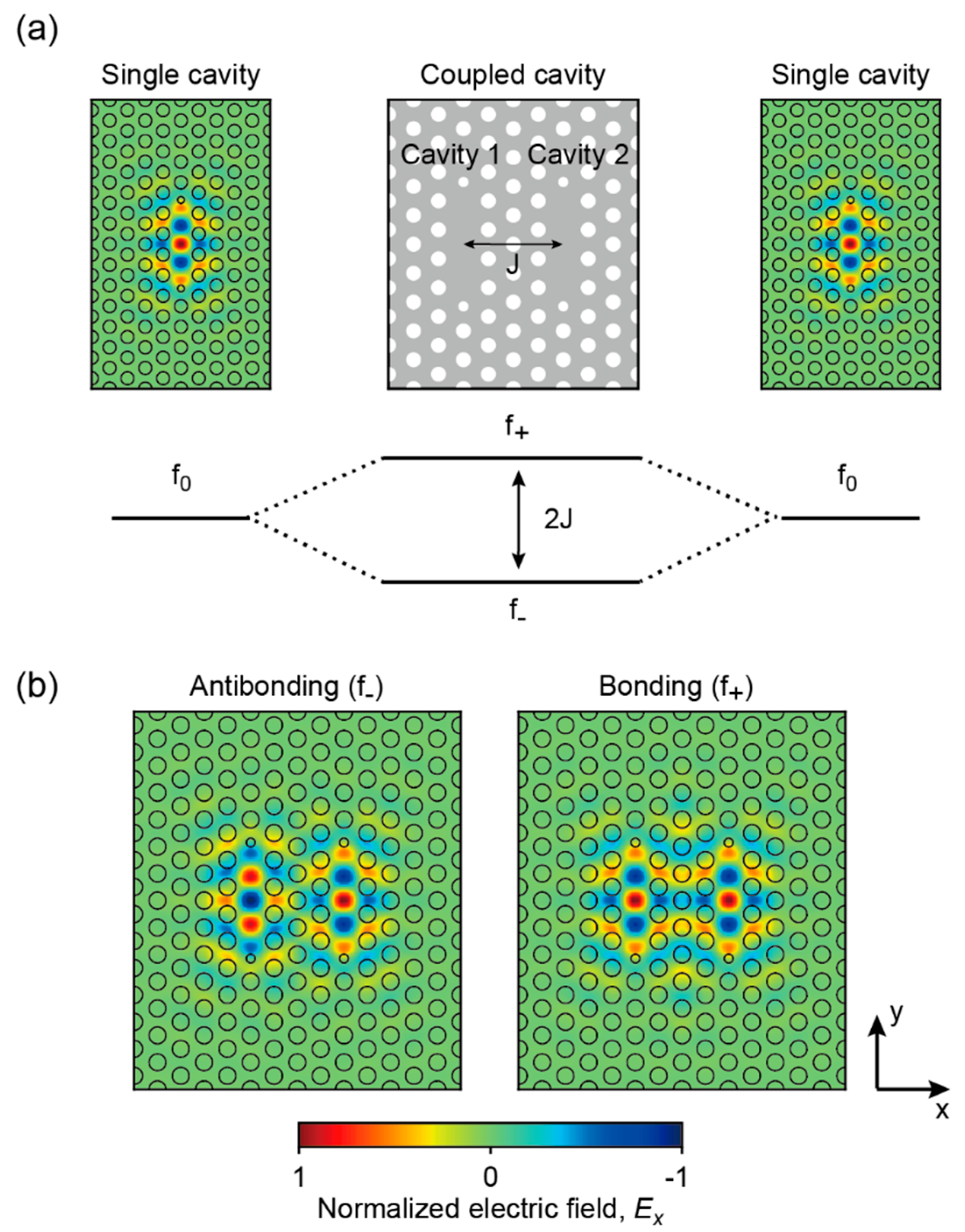
Figure 1 shows the coupled PhC cavity structure, referred to as the doubly coupled PhC cavity that we employed for non-Hermiticity control. The two identical vertical L3 line defect PhC cavities, referred to as component cavities, are horizontally coupled via three vertical lines of airholes. This coupled PhC cavity supports two independent eigenmodes that are slightly different from the one in the single component cavity in terms of eigenfrequency and field profile. These two eigenmodes originate from the coupling between the two fundamental modes (left and right panels of Figure 1a) of the individual component cavities. The resultant eigenmodes can be classified based on the spatial field distribution or symmetry with respect to the central line of the coupled cavity. The eigenmode with the symmetric (or in-phase) field distribution is known as the bonding mode (right, Figure 1b), whereas the eigenmode with the antisymmetric (or out-of-phase) field distribution is known as the antibonding mode (left, Figure 1b).
The eigen-frequencies of the bonding (f+) and antibonding modes (f–) in the coupled cavity are determined by the eigenfrequency of the single component cavity (f0) and the inter-cavity coupling constant (J). The set of coupled differential equations describing the interaction between the two component cavities is given by
where ϕ1 and ϕ2 are the wavefunctions of component cavities 1 and 2, respectively [11,15]. Based on the assumption of steady-state oscillations, ϕ(t) = exp(−2iπft), the eigenfrequencies of the doubly coupled PhC cavity are obtained as follows:
Figure 1a shows the eigen-frequency relation between the single component cavity and the doubly coupled cavity: the eigenfrequency f0 of the single component cavity is split into two eigenfrequencies, f+ and f–, of the doubly coupled cavity with a frequency difference of 2J, based on Equation (2). Equation (2) reveals that the rational design of two component cavities with controllable J can allow for the systematic tuning of eigenmodes and the corresponding eigenfrequencies in the coupled PhC cavity. Henceforth, we focus on controlling J while maintaining the structural parameters of the component cavities. As the L3 line defect PhC cavity supports a high-quality (high-Q) fundamental mode with strong light confinement near the cavity, alterations of the cavity structure can introduce undesirable complexities, which may lead to a considerable optical loss.
3.2. Coupling Control Schemes in the Doubly Coupled PhC Cavity
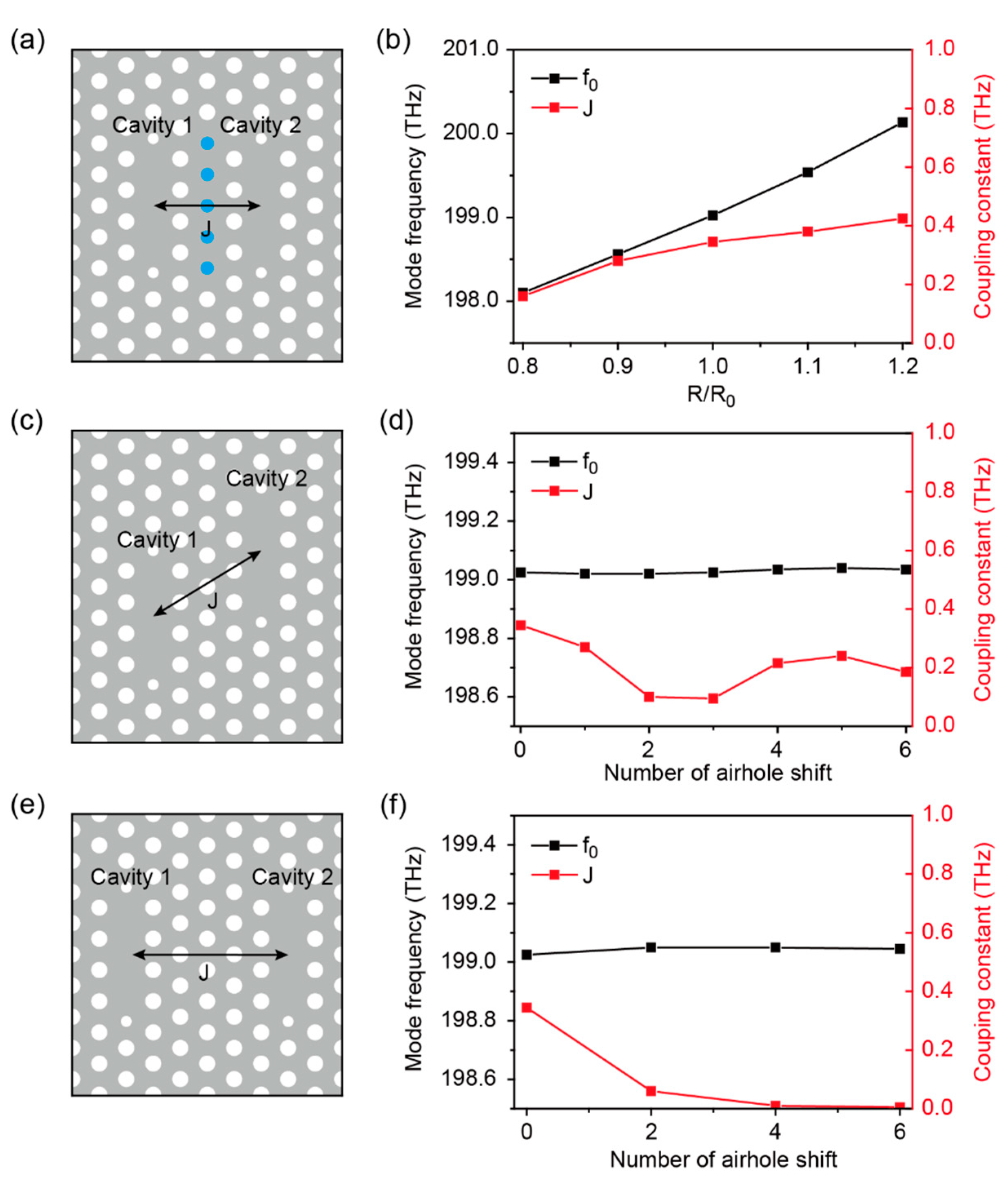
We propose three different coupling control schemes in the doubly coupled PhC cavity. First, we controlled the size of the shared airholes (blue circles, radius R) in the coupling region between the two component cavities while fixing the size of regular airholes (radius R0), as shown in Figure 2a. Figure 2b shows the calculated eigenfrequencies f0 (black) and coupling constants J (red) plotted as a function of the ratio of the shared airhole size to the regular airhole size (R/R0). As expected, the coupling constant varied in response to the change of R/R0: J slowly increased with R/R0. Moreover, the eigenfrequency sensitively varied in response to the change of R/R0 as well because the L3 line defect cavity is readily affected by the cavity size and the airholes around the cavity. Consequently, this control scheme can allow for the substantial tuning of eigenfrequencies of bonding and antibonding modes with small structural variations.
Second, we vertically shifted one of the component cavities (cavity 2) using a designated number of airholes with respect to the other component cavity (cavity 1), as shown in Figure 2c. Although the vertical shift only allows for discrete levels of control regarding J, unlike the shared airhole-based control, this scheme preserves the fundamental modes of the individual component cavities well. Figure 2d shows the calculated eigenfrequencies, f0 (black), and coupling constants, J (red), plotted as a function of the number of airhole shifts. Interestingly, while the eigenfrequency remained almost constant, the coupling constant exhibited more structured behaviors as the number of shifts increased. For example, at first, the maximum J at zero shift decreased as the number of shifts increased; subsequently, it became minimum at three airhole shifts and recovered at five airhole shifts. We attribute this characteristic behavior to the unique field distribution of the fundamental mode, which shows directional field leakage at 60 degrees to the cavity axis.
Third, we increased the level of control of J by laterally shifting cavity 2 using the designated number of airholes with respect to cavity 1, as shown in Figure 2e. This lateral shift entailed a pairwise correspondence between airholes owing to the triangular symmetry of the PhC structure, such that the centers of the component cavities could be aligned horizontally. As expected, the fundamental eigenfrequency f0 (black) showed a trend similar to the one observed in the vertical shift scheme, but the coupling constant J (red) exhibited a drastic decrease as the number of airhole shifts increased (Figure 2f). Taken together, the vertical and lateral shift schemes are more desirable than the shared airhole control scheme because they guarantee the independent control of J while keeping f0 unaffected. In addition, the vertical shift scheme allows for finer levels of control of J than the lateral one, which is beneficial for the detailed study of non-Hermiticity when an asymmetric gain is introduced. Therefore, we exclusively employ the vertical shift scheme for the systematic tuning of non-Hermiticity (explained in the following section).
3.3. Asymmetric Gain in the Doubly Coupled PhC Cavity
The introduction of universal optical gain to an optical cavity system does not have a significant effect on the eigenmodes and eigenfrequency because the entire cavity structure and the correspondingly excited modes equally experience the gain in space. However, applying a spatially asymmetric optical gain to a coupled cavity system can introduce unanticipated behaviors with regard to the eigenmodes and eigenfrequencies, thereby entailing the concept of PT symmetry in a non-Hermitian optical system [10,12,15]. The optical gain with controlled levels of asymmetricity can affect the state of the non-Hermitian optical system, that is, whether the system is in the unbroken or broken PT-symmetric phase. For example, at moderate levels of asymmetric optical gain, the system remains in the unbroken PT-symmetric phase, supporting two non-degenerate eigenmodes, that is, the bonding and antibonding modes. However, when the asymmetricity reaches a critical point, known as the exceptional point (EP), the phase transition between the two PT-symmetric phases occurs. Importantly, at the EP, these two eigenmodes are degenerated, yielding the same eigenfrequency [15,16,17]. Furthermore, for higher levels of asymmetricity than that of the EP, the system enters the broken PT-symmetric phase and supports single degenerate super-modes. We apply this concept of the non-Hermitian optical system to our doubly coupled PhC cavity and achieve systematic manipulation of the eigenmodes and eigenfrequencies.
In our non-Hermitian coupled cavity system, the eigenfrequencies are determined by the fundamental eigen-frequency (f0), the inter-cavity coupling constant (J), and the individual optical gain and loss in component cavities. Considering all of these, the previous set of coupled differential equations is modified as follows:
where γ1 and γ2 are optical gains in component cavities 1 and 2, respectively. We assumed that the two component cavities have the same optical loss, i.e., κ, and the eigenmodes are in a steady state. Based on Equation (3), the eigenfrequencies of the two eigenmodes are given by
where Δγ = (γ2 − γ1)/2 and γavg = (γ1 + γ2)/2 are the gain contrast and average gain, respectively. We systematically change the value of Δγ to control the level of the asymmetricity in the optical gain. The result of Equation (4) reveals important features: First, the eigenfrequencies in Equation (4) are determined by the interplay between the coupling constant J and the gain contrast Δγ. Subsequently, the frequency difference between f+ and f− can be tuned based on the gain contrast level. Second, the real part of the eigenfrequencies has two different values when J2 > Δγ2 (the unbroken PT-symmetric phase), but unexpectedly, it has a single value when J2 < Δγ2 (the broken PT-symmetric phase). Third, the imaginary part of the eigenfrequencies can have either a positive or negative value depending on the relative magnitude of (Δγ2 − J2)1/2 and γavg − κ when the system is in the broken PT-symmetric phase. These results indicate that one can tune the real and imaginary parts of complex eigenfrequencies, determine the system symmetry phase, and consequently manipulate the non-Hermiticity by simply introducing different levels of gain in component cavities 1 and 2.
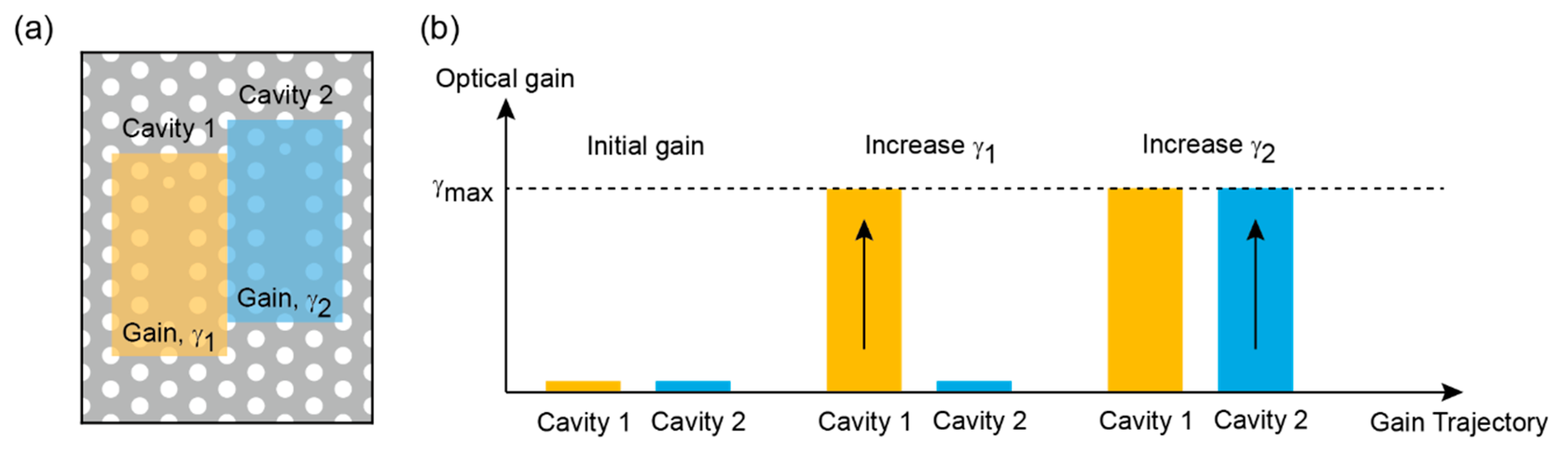
Figure 3 shows our approach for exploring the control of non-Hermiticity. As mentioned earlier, to independently control J while keeping f0 constant, we employed the doubly coupled PhC cavity in which one of the component cavities was vertically shifted (cavity 2). Then, we introduced different optical gains, γ1 (shaded yellow box) and γ2 (shaded blue box), to component cavities 1 and 2 by systematically changing the extinction coefficient Kslab (Figure 3a). At the initial stage, we started with two passive component cavities, then slowly increased γ1 to the maximum gain γmax while keeping cavity 2 passive; finally, γ2 was increased to the maximum gain γmax while keeping γ1 = γmax, as shown in Figure 3b.
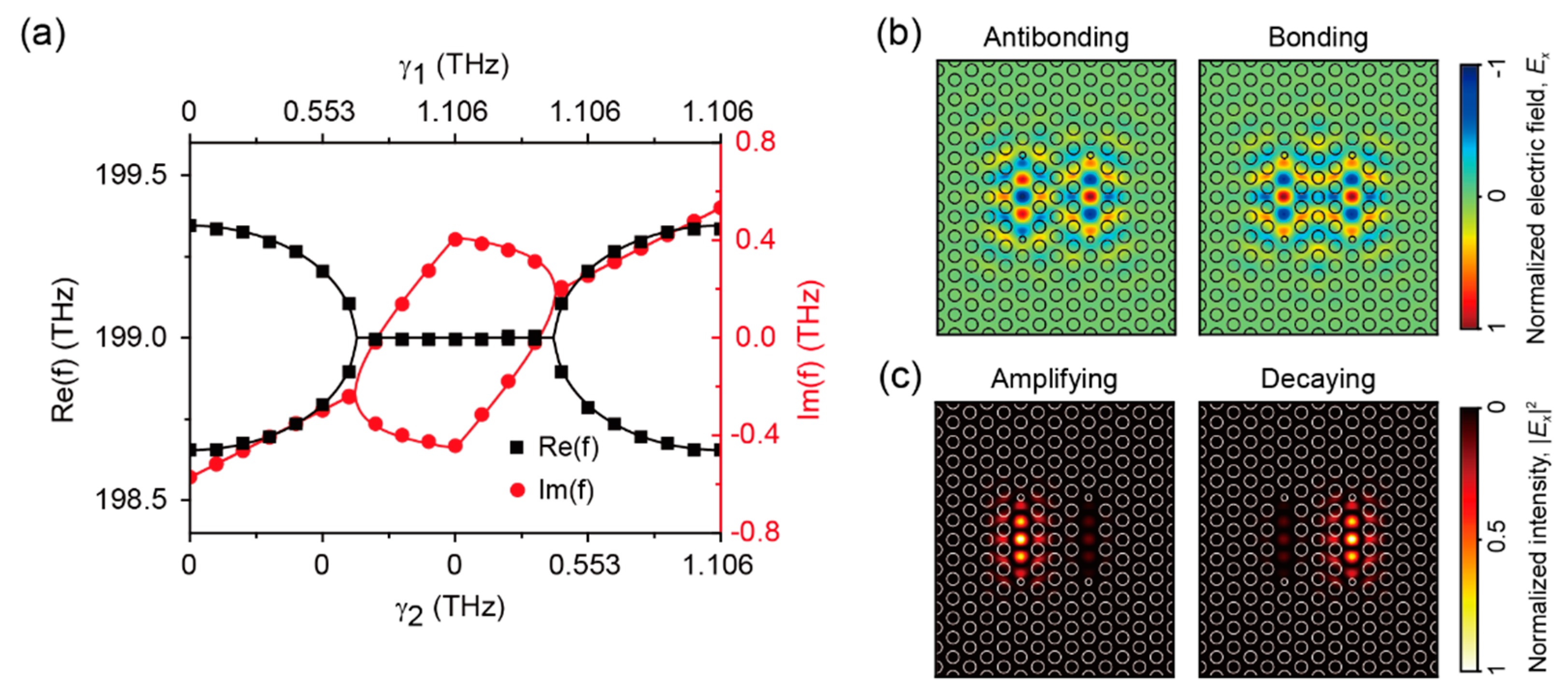
Figure 4 shows the results. First, we employed the doubly coupled PhC cavity without performing vertical airhole shifting and calculated the real (Re(f), black squares) and imaginary parts (Im(f), red circles) of the complex eigenfrequencies as a function of the gain trajectory presented in Figure 3b and Figure 4a. Analytical solutions (black and red lines) obtained from Equation (4) were co-plotted, and they agree well with the numerical simulations. The model parameters such as Δγ, γavg, κ, and J were obtained from the numerical simulations by fitting them with Equation (4). The results clearly reveal the unique non-Hermiticity nature, exhibiting the evolution of the state from the unbroken to the broken PT-symmetric phase and vice versa with phase transitions occurring at the EPs. For example, the real part of the eigenfrequencies, Re(f), shows two distinct eigenmodes (i.e., bonding (Re(f+)) and antibonding (Re(f−)) modes) at Δγ = 0, as expected from Equation (4). As |Δγ| increases, the eigenfrequency difference between Re(f+) and Re(f−) reduces, and the system is in the unbroken PT symmetry phase. At the EP with |Δγ| = 0.345 THz, which is equal to J, the two eigenmodes coalesce and become a single degenerate eigenmode. As |Δγ| further increases, the system enters the broken PT-symmetric phase, and the degenerate eigenmode holds until |Δγ| = 1.106 THz. In contrast, the imaginary part of the eigenfrequencies, Im(f), exhibits an opposite development. Im(f) of two eigenmodes are both equal to each other when |Δγ| < 0.345 THz, which indicates that the two eigenmodes experience an equal amount of optical gain. However, at |Δγ | values larger than that at the EP, Im(f) is bifurcated, independently contributing to the two degenerate eigenmodes. Consequently, the degenerate eigenmodes are classified into two kinds of eigenmodes that experience positive (amplifying mode) and negative (decaying mode) optical gain. The maximum bifurcation of Im(f) is obtained when |Δγ| = |Δγ|max (i.e., 1.106 THz). Figure 4b,c shows the field and intensity profiles of the eigenmodes in the unbroken and broken PT-symmetric phases. Figure 4b shows the field distributions of the out-of-phase antibonding and in-phase bonding modes at γ1 = γ2 = γmax. As |Δγ| increases, these field distributions slowly alter in response to the relative magnitude of γ1 and γ2. For example, at optical gains of γ1 = γmax and γ2 = 0, the fields are confined exclusively in cavity 1 for the amplifying mode and in cavity 2 for the decaying mode (Figure 4c). This unique non-Hermitian behavior can be exploited in experiments to help develop a new active tuning mechanism, without altering the cavity structure, that enables dramatic changes in terms of resonant frequency and field profile. In laser applications, for example, one can readily excite two eigenmodes (e.g., bonding and antibonding modes) with slightly asymmetric pumping and judiciously induce an unbalanced modal competition that favorably acts on one of the eigenmodes, resulting in the final laser mode [8,17,18]. In addition, one can exclusively excite a single amplifying laser mode by applying for the further increased levels of the asymmetry.
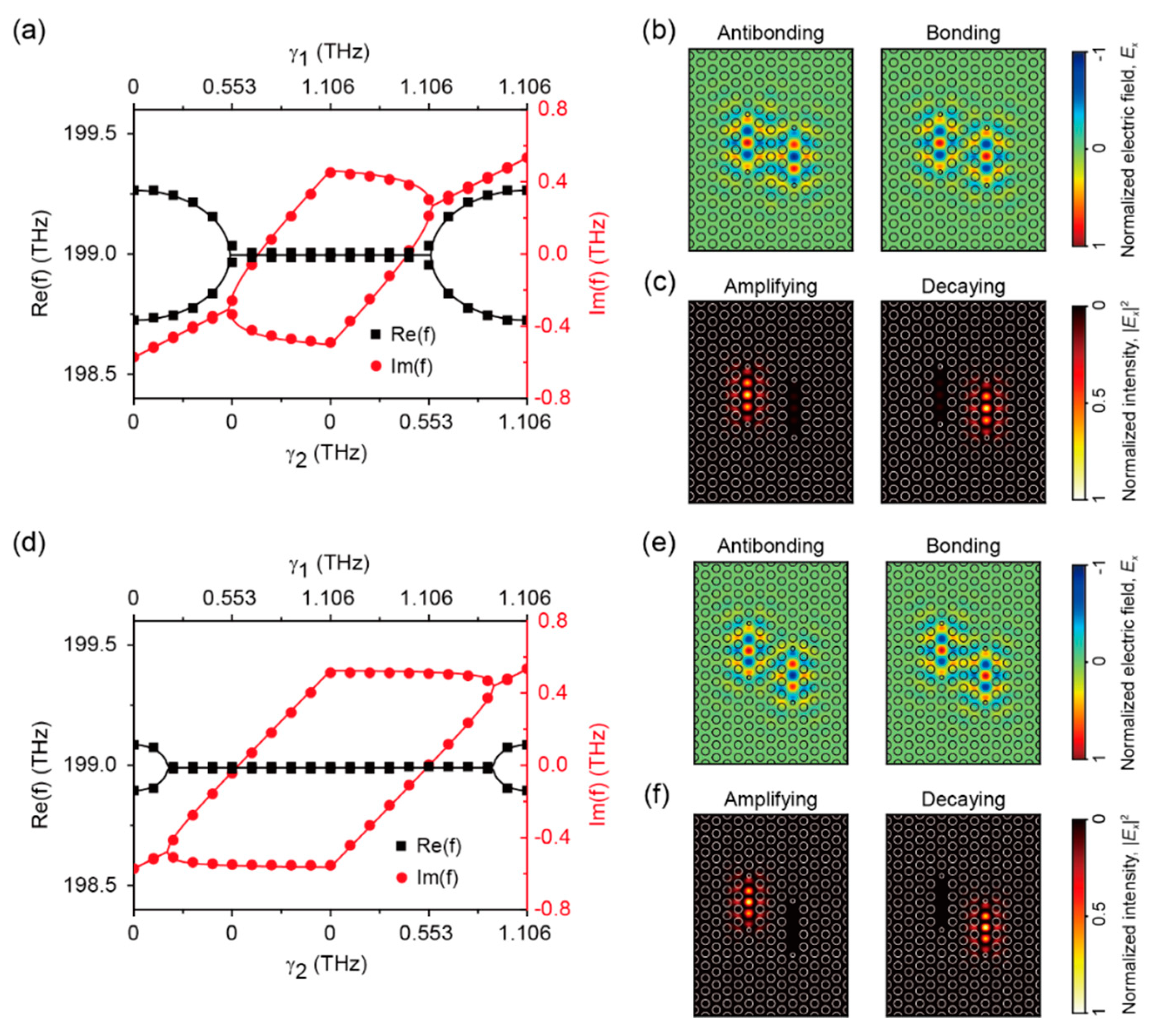
Next, we performed the vertical airhole shifting of cavity 2 to independently control J in Equation (4) and observed the corresponding changes in non-Hermiticity (Figure 5). The calculated complex eigenfrequencies of the coupled cavity with one and two vertical airhole shifts are shown in Figure 5a,d, respectively. As discussed earlier, the vertical shift results in the reduction of J, which suggests that the system is substantially affected by the gain contrast |Δγ|. For example, the eigenmode coalescence in Re(f) with bifurcation in Im(f) appears at EPs with lower values of |Δγ| (e.g., 0.271 THz in (a) and 0.100 THz in (d)). In addition, regarding the decrease in γ2 from γmax with fixed γ1 = γmax, one branch of the bifurcated Im(f), which contributes to the amplifying mode, varies slowly, whereas the other branch undergoes an abrupt change until |Δγ| equals |Δγ|max. On the contrary, regarding the increase in γ1 for two passive cavities (γ1 = γ2 = 0), the same branches exhibit an opposite behavior. These controlled non-Hermitian properties can be advantageously exploited in several applications. For example, the readily obtainable phase transition with low asymmetric gain enables sensitive and rapid switching operations between optical states. Moreover, the stable development of mode amplification guarantees steady and robust single-mode operation at varied pumping powers, which is hardly obtainable in nano and microcavity-based optical devices. Figure 5b,c,e,f show the field (Figure 5b,e) and intensity profiles (Figure 5c,f) of the non-degenerate (γ1 = γ2 = γmax) and degenerate eigen-modes (γ1 = γmax, γ2 = 0) in the coupled cavity with one and two vertical airhole shifts. Despite the applied structural modifications, which slightly break the structural symmetry, the mode profiles are similar to those shown in Figure 4b,c. This result directly confirms that our analysis of the non-Hermitian optical system based on Equation (4) is effectively valid for describing the asymmetrically coupled cavity system and for explaining the control of non-Hermitian properties. Taken together, the asymmetric optical gain introduced to the doubly coupled PhC cavity can enable controllable interplay between Δγ and J. This helps in simultaneously tuning the eigenfrequency and field profile in a fixed cavity structure, and it provides an unprecedented active tuning mechanism for coupled cavity-based optical devices.
4. Conclusions
In summary, we have investigated the cavity modes in a non-Hermitian doubly coupled PhC cavity system with the systematic manipulation of the intercavity coupling constant. In the doubly coupled PhC cavity, the coupling constant can be tuned by changing the cavity structure, such as by varying the sizes of the shared airholes or via the discrete vertical/lateral airhole shifting of one of the component cavities. We found that discrete airhole shifting, which yields a tunable coupling constant with a constant fundamental eigenfrequency, is more desirable for non-Hermicity control. In addition, we analyzed the evolution of eigenmodes and eigenfrequencies in the non-Hermitian doubly coupled PhC cavity system by varying the coupling constant via the vertical shifting of one of the component cavities and by systematically controlling the spatially asymmetric optical gain. It was revealed that the interplay between the gain contrast and the coupling constant is crucial for determining the EP. This unique non-Hermitian behavior with EP can provide a new method to control laser emission by the additional tuning knob and asymmetric optical gain, which helps in increasing the design flexibility of the cavity structures. We believe that the proposed method of manipulation of non-Hermicity in the coupled PhC cavity system can allow us to develop a novel actively tunable PhC cavity laser, using a fixed cavity structure, that exclusively excites a steady and robust single amplifying laser mode.
Author Contributions
Conceptualization, K.-H.K. and Y.-S.N.; methodology, M.S. and E.S.H.K.; validation, K.-H.K., E.S.H.K., and Y.-S.N.; writing—original draft preparation, K.-H.K.; writing—review and editing, Y.-S.N.; funding acquisition, K.-H.K., E.S.H.K., and Y.-S.N. All authors have read and agreed to the published version of the manuscript.
Funding
K.-H.K. acknowledges support from the National Research Foundation of Korea (NRF) grant funded by the Korean government (MSIT) (2019R1C1C1006681). E.S.H.K. acknowledges support from the National Research Foundation of Korea (NRF) grant funded by the Korean government (MSIT) (2020R1A2C1102558). Y.-S.N. acknowledges support from the National Research Foundation of Korea (NRF) grant funded by the Korean government (2018R1C1B3001130).
Conflicts of Interest
The authors declare no conflict of interest.
References
- Joannopoulos, J.D.; Johnson, S.G.; Winn, J.N.; Meade, R.D. Photonic Crystals: Molding the Flow of Light; Princeton University Press: Princeton, NJ, USA, 2011. [Google Scholar]
- O’Brien, J.L.; Furusawa, A.; Vučković, J. Photonic quantum technologies. Nat. Photonics 2009, 3, 687–695. [Google Scholar] [CrossRef] [Green Version]
- Park, H.-G.; Barrelet, C.J.; Wu, Y.; Tian, B.; Qian, F.; Lieber, C.M. A wavelength-selective photonic-crystal waveguide coupled to a nanowire light source. Nat. Photonics 2008, 2, 622–626. [Google Scholar] [CrossRef]
- Park, H.-G.; Kim, S.-H.; Kwon, S.-H.; Ju, Y.-G.; Yang, J.-K.; Baek, J.-H.; Kim, S.-B.; Lee, Y.-H. Electrically driven single-cell photonic crystal laser. Science 2004, 305, 1444–1447. [Google Scholar] [CrossRef] [PubMed]
- Englund, D.; Fattal, D.; Waks, E.; Solomon, G.; Zhang, B.; Nakaoka, T.; Arakawa, Y.; Yamamoto, Y.; Vučković, J. Controlling the spontaneous emission rate of single quantum dots in a two-dimensional photonic crystal. Phys. Rev. Lett. 2005, 95, 013904. [Google Scholar] [CrossRef] [PubMed] [Green Version]
- Englund, D.; Majumdar, A.; Bajcsy, M.; Faraon, A.; Petroff, P.; Vučković, J. Ultrafast photon-photon interaction in a strongly coupled quantum dot-cavity system. Phys. Rev. Lett. 2012, 108, 093604. [Google Scholar] [CrossRef] [PubMed] [Green Version]
- Gerace, D.; Türeci, H.E.; Imamoglu, A.; Giovannetti, V.; Fazio, R. The quantum-optical josephson interferometer. Nat. Phys. 2009, 5, 281–284. [Google Scholar] [CrossRef] [Green Version]
- Hamel, P.; Haddadi, S.; Raineri, F.; Monnier, P.; Beaudoin, G.; Sagnes, I.; Levenson, A.; Yacomotti, A.M. Spontaneous mirror-symmetry breaking in coupled photonic-crystal nanolasers. Nat. Photonics 2015, 9, 311–315. [Google Scholar] [CrossRef] [Green Version]
- Caselli, N.; Intonti, F.; La China, F.; Biccari, F.; Riboli, F.; Gerardino, A.; Li, L.; Linfield, E.H.; Pagliano, F.; Fiore, A.; et al. Generalized fano lineshapes reveal exceptional points in photonic molecules. Nat. Commun. 2018, 9, 396. [Google Scholar] [CrossRef] [PubMed]
- Brandstetter, M.; Liertzer, M.; Deutsch, C.; Klang, P.; Schöberl, J.; Türeci, H.E.; Strasser, G.; Unterrainer, K.; Rotter, S. Reversing the pump dependence of a laser at an exceptional point. Nat. Commun. 2014, 5, 4034. [Google Scholar] [CrossRef] [PubMed] [Green Version]
- El-Ganainy, R.; Khajavikhan, M.; Ge, L. Exceptional points and lasing self-termination in photonic molecules. Phys. Rev. A 2014, 90, 013802. [Google Scholar] [CrossRef] [Green Version]
- Hodaei, H.; Miri, M.-A.; Heinrich, M.; Christodoulides, D.N.; Khajavikhan, M. Parity-time–symmetric microring lasers. Science 2014, 346, 975–978. [Google Scholar] [CrossRef] [PubMed]
- Feng, L.; Wong, Z.J.; Ma, R.-M.; Wang, Y.; Zhang, X. Single-mode laser by parity-time symmetry breaking. Science 2014, 346, 972–975. [Google Scholar] [CrossRef] [PubMed]
- Peng, B.; Özdemir, Ş.K.; Rotter, S.; Yilmaz, H.; Liertzer, M.; Monifi, F.; Bender, C.M.; Nori, F.; Yang, L. Loss-induced suppression and revival of lasing. Science 2014, 346, 328–332. [Google Scholar] [CrossRef] [PubMed] [Green Version]
- Kim, K.-H.; Hwang, M.-S.; Kim, H.-R.; Choi, J.-H.; No, Y.-S.; Park, H.-G. Direct observation of exceptional points in coupled photonic-crystal lasers with asymmetric optical gains. Nat. Commun. 2016, 7, 13893. [Google Scholar] [CrossRef] [PubMed] [Green Version]
- Özdemir, Ş.K.; Rotter, S.; Nori, F.; Yang, L. Parity–time symmetry and exceptional points in photonics. Nat. Mater. 2019, 18, 783–798. [Google Scholar] [CrossRef]
- Wenzel, H.; Bandelow, U.; Wünsche, H.J.; Rehberg, J. Mechanisms of fast self pulsations in two-section DFB lasers. IEEE J. Quantum Electron. 1996, 32, 69–78. [Google Scholar] [CrossRef]
- Smith, P.W. Mode selection in lasers. Proc. IEEE 1972, 60, 422–440. [Google Scholar] [CrossRef]
Figure 1.
Doubly coupled photonic crystal (PhC) cavity. (a) Coupled PhC cavities that consist of two identical defect PhC cavities. The fundamental mode of each single cavity is shown to the left and right of the coupled cavities. The frequency diagram of the resonant modes in the single and coupled cavities is shown. f0 is the eigenfrequency of the fundamental mode of the single cavity, and J is the coupling constant in the coupled cavities. (b) Calculated field profiles of the two eigenmodes in the doubly coupled PhC cavity: out-of-phase anti-bonding (f−) and in-phase bonding mode (f+). The electric field of the cavity modes was polarized in the x-direction.

Figure 2.
Coupling control schemes in doubly coupled PhC cavity. (a,c,e) Three different coupling control methods: (a) changing the size of the shared airholes (blue dots) between two component cavities, (c) vertical shifting of cavity 2, and (e) lateral shifting of cavity 2. (b,d,f) The estimated fundamental mode frequency of a single cavity, f0, and the intercavity coupling constant J as a function of (b) the ratio of the shared airhole size to the regular airhole size (R/R0), (d) the number of vertical airhole shifts of cavity 2, and (f) the number of lateral airhole shifts of cavity 2.

Figure 3.
Asymmetric optical gain in doubly coupled PhC cavity. (a) Asymmetric optical gain in doubly coupled PhC cavity with gain γ1 in cavity 1 (yellowish shaded area) and gain γ2 in cavity 2 (bluish shaded area). (b) Asymmetric gain trajectory in doubly coupled PhC cavity. The initial gain was set to zero. Next, γ1 was increased to the maximum gain γmax (yellow bar) and then γ2 was increased to γmax while γ1 was kept equal to γmax (blue bar).

Figure 4.
Evolution of eigenfrequencies in doubly coupled PhC cavity. (a) The calculated eigenfrequencies of the coupled cavity modes in the doubly coupled PhC cavity without vertical airhole shifting. The optical gain in component cavities 1 and 2 followed the trajectory shown in Figure 3b. The real (black squares) and imaginary parts (red circles) of the eigenfrequencies obtained from the numerical full-wave simulation were co-plotted with the analytical solutions (black and red lines) obtained from Equation (4). (b) The cavity mode profiles of the antibonding and bonding modes at γ1 = γ2 = γmax. The field profiles clearly show the in-phase and out-of-phase characteristics in the coupled modes. (c) Calculated intensity profiles of the amplifying and decaying modes at γ1 = γmax and γ2 = 0. The intensity distributions clearly show the strong and spatially exclusive confinement of the fields of the amplifying and decaying modes.

Figure 5.
Eigenfrequencies of doubly coupled PhC cavity with vertical airhole shifting. (a,c) The calculated eigenfrequencies of the coupled cavity modes in a doubly coupled PhC cavity with (a) one and (c) two vertical airhole shifts. The optical gain in component cavities 1 and 2 followed the trajectory shown in Figure 3b. The real (black squares) and imaginary parts (red circles) of eigenfrequencies obtained from the numerical full-wave simulation were co-plotted with analytical solutions (black and red lines) obtained from Equation (4). (b,e) The cavity mode profiles of the antibonding and bonding modes at γ1 = γ2 = γmax in the doubly coupled PhC cavity with (b) one and (d) two vertical airhole shifts. The field distributions clearly show the in-phase and out-of-phase characteristics in the coupled modes. (c,f) The intensity profiles of the amplifying and decaying modes at γ1 = γmax and γ2 = 0 in the doubly coupled PhC cavity with (c) one and (f) two vertical airhole shifts.

Publisher’s Note: MDPI stays neutral with regard to jurisdictional claims in published maps and institutional affiliations. |
© 2020 by the authors. Licensee MDPI, Basel, Switzerland. This article is an open access article distributed under the terms and conditions of the Creative Commons Attribution (CC BY) license (http://creativecommons.org/licenses/by/4.0/).
Share and Cite
MDPI and ACS Style
Kim, K.-H.; Sujak, M.; Kang, E.S.H.; No, Y.-S. Tunable non-Hermiticity in Coupled Photonic Crystal Cavities with Asymmetric Optical Gain. Appl. Sci. 2020, 10, 8074. https://0-doi-org.brum.beds.ac.uk/10.3390/app10228074
AMA Style
Kim K-H, Sujak M, Kang ESH, No Y-S. Tunable non-Hermiticity in Coupled Photonic Crystal Cavities with Asymmetric Optical Gain. Applied Sciences. 2020; 10(22):8074. https://0-doi-org.brum.beds.ac.uk/10.3390/app10228074
Chicago/Turabian StyleKim, Kyoung-Ho, Muhammad Sujak, Evan S. H. Kang, and You-Shin No. 2020. "Tunable non-Hermiticity in Coupled Photonic Crystal Cavities with Asymmetric Optical Gain" Applied Sciences 10, no. 22: 8074. https://0-doi-org.brum.beds.ac.uk/10.3390/app10228074
Note that from the first issue of 2016, this journal uses article numbers instead of page numbers. See further details here.