Optimization Design of the Spaceborne Connecting Structure for a Lightweight Space Camera


1
Changchun Institute of Optics, Fine Mechanics and Physics, Chinese Academy of Sciences, Changchun 130033, China
2
University of Chinese Academy of Sciences, Beijing 100049, China
3
Chang Guang Satellite Technology Co., Ltd., Changchun 130031, China
*
Author to whom correspondence should be addressed.
Appl. Sci. 2020, 10(22), 8249; https://0-doi-org.brum.beds.ac.uk/10.3390/app10228249
Submission received: 10 September 2020
/
Revised: 9 October 2020
/
Accepted: 14 October 2020
/
Published: 20 November 2020
(This article belongs to the Collection Optical Design and Engineering)
Abstract
:For a lightweight space camera installed vertically with a satellite platform, due to the different conditions between ground and orbit, the relative deformation between the camera and the satellite platform results in a drift of the camera line of sight (LOS), which affects the imaging quality. This paper proposed an optimization method for the spaceborne connecting structure considering the camera LOS drift. By using a variable density topology optimization method, the configuration of the connecting structure was obtained. Based on the configuration, the sensitivity of its size parameters to the system’s performance was analyzed. Analysis data showed that the size parameters have an obvious influence on the camera LOS shift. In order to obtain the optimal combination of size parameters, a multi-objective parametric optimization model was established. Finally, engineering analysis of the optimized structure showed that the system performances meet the design requirements of the satellite, and the lightweight ratio of the connecting structure reaches 54%. This study provides a reference for the design of other similar structures for space cameras.
1. Introduction
With the rapid development of the aerospace industry, remote sensing technology has been widely used in various fields of the national economy. At the same time, people put forward higher requirements for performances of space cameras [1]. The requirements of high performances mean that the camera has a large aperture and long focal length, which inevitably leads to the increase of camera mass and launch cost. Therefore, it is necessary to optimize the optomechanical structures of the camera so that it achieves a high lightweight ratio and meets space performance requirements [2]. The lightweight ratio of structures is the ratio of mass removed by optimization design to initial mass. The higher its value, the higher the lightness of the structure and the lower the launch cost of the space cameras. The spaceborne connecting structure of the space cameras provides installation interfaces for the space camera and satellite platform, and it reduces the influence of external loads on the camera. So, the optimization design of the connecting structure is very important for the development of a high-performance space camera.
So far, there are two main types of connection between a space camera and satellite platform: vertical installation and horizontal installation. Vertical installation has the advantages of uniform force, good static mechanical performance, and it is not easy to be affected by external loads. It is generally used in space cameras with high lightweight ratio and low structural stiffness requirements, such as the Skysat-1 video satellite launched by Skybox [3], which is an American company, and Worldview series satellites developed by Digital Globe [4]. Horizontal installation has advantages of a low centroid of the whole satellite and a high satellite fundamental frequency. It is generally used in space cameras with high stiffness requirements, such as the Sofia Space Telescope designed by the German Aerospace Center [5]. In this paper, in order to ensure the suitable lightweight ratio of the camera and stability of mirrors, the vertical installation is adopted.
There have been a lot of research studies on the optomechanical design. Isaac Weingrod, from the Lockheed Martin Space Systems company, designed precise bipod flexible support structures for the optical elements of NASA’s IRIS spectrometer and realized the accurate installation of the optical elements. The bipod mounts successfully carried nine different optics through environmental testing and into orbit, which demonstrated the kinematic structures without fiction can be applied to most optic mount designs [6]. Riva et al. proposed an optomechanical structure optimization method based on coupling sensitivity matrix analysis with an optimized telescope with an aperture of 600 mm and obtained a suitable lightweight ratio. Their idea is to reduce the number of iterations in a multi-variable structural optimization, taking advantage of the embedded sensitivity routines that are available both in FEA software and in ray-tracing software. It can be used simply for performance prediction or for optimization strategies [7]. Mikio Kunita applied Genetic algorithm (GA) to the truss-type main support structure of a space camera and realized a lightweight design of the main support structure. Genetic algorithm is a powerful tool to optimize a multi-objective optimization problem. They developed an optimization program employing a GA in order to obtain the main support structure design, which satisfies an acceptable homologous deformation with lightweight [8]. Yi-Cheng Chen et al. wrote a program to process the deformation data of mirror surface nodes into a root mean square (RMS) value and optimized the mirror and its support structure with the RMS value as an objective. They used FEA to determine mirror surface deformation; then, the deformation surface nodal data were transferred into Zernike polynomials through MATLAB optomechanical transfer codes to calculate the resulting optical path difference (OPD) and optical aberrations. By using their self-developed Tcl script, an optimum design of mirrors was achieved [9]. These studies show the practicability of the kinematic structures without fiction in the optical machinery and the development of the multi-objective optimization design of optomechanical structures. However, these are designs based on the known structures. It is still necessary to explore the configuration design methods of optomechanical structures and further structural optimization design methods integrating optical metrics.
Topology optimization is one of the most effective methods in the structural conceptual design stage, which has attracted extensive attention in aerospace, automotive, and civil engineering. Some researchers have applied the topology optimization method to the design of optomechanical structures. Park et al. studied the topology optimization technology of a multispectral space camera, calculated the mass of its mirror and the sensitivity of the camera’s Strehl ratio by using the direct differentiation method, and obtained topology optimization results of mirrors under different mass constraints by an optimality criteria method [10]. Rui et al. established a topology optimization model with the mirror shape error caused by gravity and thermal effects as an objective function and the first-order natural frequency of mirror assembly as a constraint condition. The results showed that this optimization method significantly improves the optical performance of the mirror assembly [11]. These studies demonstrated the feasibility of topology optimization in the design of optomechanical structures.
In this paper, we present an optimization method considering the LOS drift for designing a connecting structure. Qualitative analysis for the camera LOS drift is conducted, and the LOS drift is decomposed into quantities that are easy to analyze. The initial configuration of the connecting structure is obtained by topology optimization considering the relative displacements between mirrors. The optimal size parameters are obtained with detailed parameters optimization. Finally, performance analysis and evaluation results verify the effectiveness of the optimization method.
2. Connecting Structure Design Principle
2.1. Decomposition of Camera LOS Drift
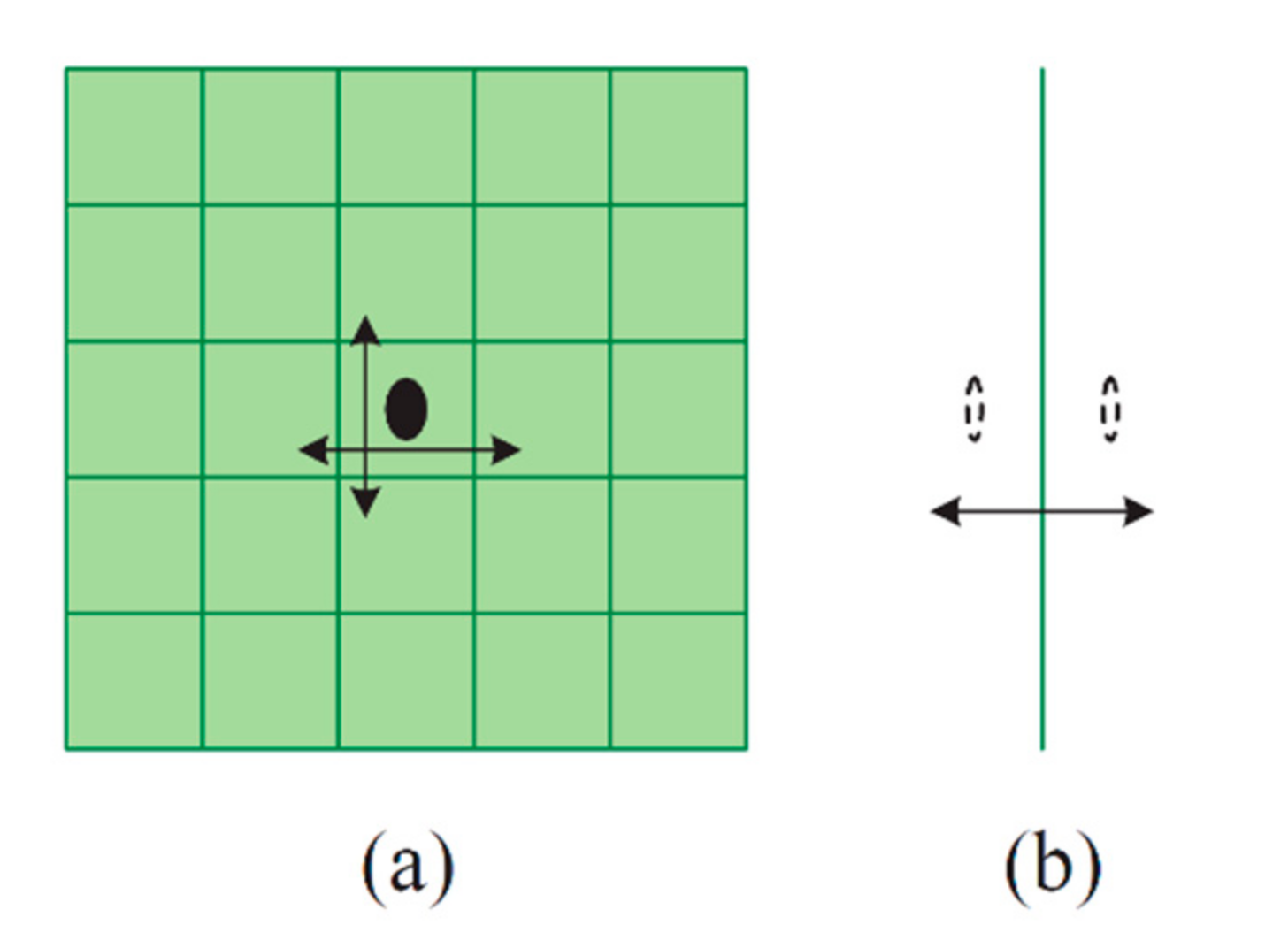
For an imaging system, under the influence of the external environment, the optical elements will move slightly, which makes the image of a static object move in the image plane. This phenomenon is called camera LOS drift, as shown in Figure 1. Due to the camera LOS drift, the image on the detector of the camera is not in the ideal position, and it may even move out of the image plane, which seriously affects the image quality. A typical design objective of an imaging system is to limit the drift within a small part of a pixel [12]. LOS drift can be obtained by using the ray tracing method; however, it takes much time and cannot be used in mechanical analysis. In mechanical analysis, the displacement of mirror finite element nodes can be analyzed by the finite element method. By processing the displacement data, the rigid body motions of mirrors were obtained, which reflects the amount of the camera LOS drift.
A few remarks were made in the following regarding the relative displacements between mirrors. When the secondary mirror and primary mirror move in the same direction, it has a compensation effect on the LOS drift. On the contrary, when the displacement in the same direction is opposite, the LOS drift will increase. In addition, in the process of camera alignment, the primary mirror is generally used as the benchmark to install and adjust the secondary mirror. Therefore, by constraining the relative displacements between mirrors, the LOS drift can be suppressed.
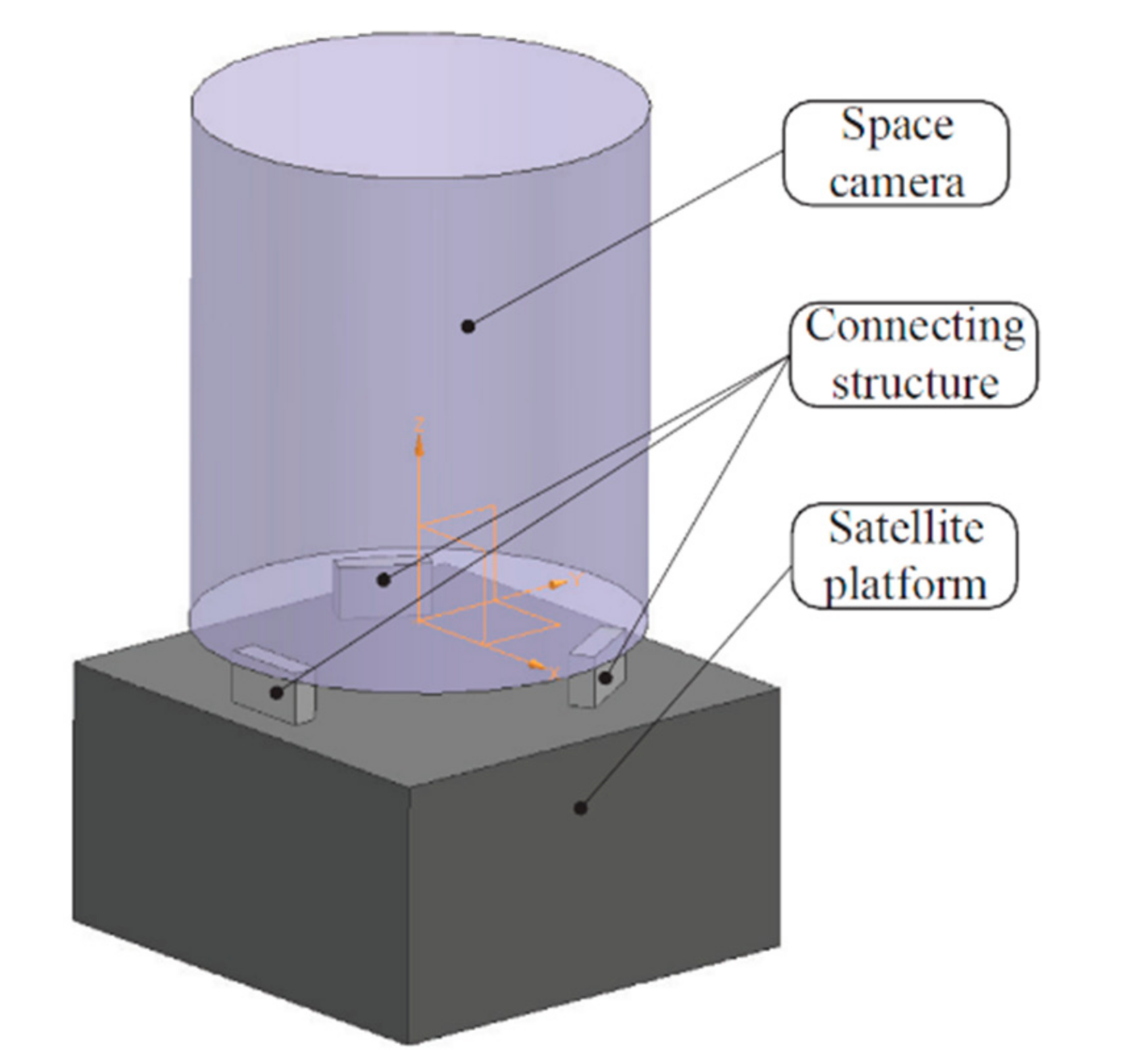
In this study, the aperture of the camera is 0.26 m, and the distance between the primary mirror and the second mirror is 0.40 m. Due to the influence of the external environment and thermal control accuracy of the space camera, the actual working temperature may have a maximum temperature difference of 4 °C (actually less than 4 °C). Under the influence of the temperature difference, the connecting structure deforms elastically, and the deformation between components will degrade the camera performance. In addition, the camera is also affected by 1 g gravity in the state of adjustment. After comprehensive consideration, the structure design requirements are that the relative linear displacements between the mirrors of the space camera should be no more than 10 μm, and the relative angular displacements should be no more than 10″ under external loads. Considering the dynamic performance, the first natural frequency of the optomechanical structure is required to be no less than 100 Hz [13]. The relationship between the spaceborne connecting structure and camera is shown in Figure 2.
2.2. Relative Displacement of Mirrors
Under the action of external loads, mirrors have a small displacement, which is also called rigid body displacement, including linear displacement and angular displacement. By establishing a camera finite element model, the mirror surface is divided into finite nodes. The rigid body motions of mirrors can be obtained by calculating the average rigid body displacement of surface nodes [14]. In this case, building a multi-point flexible constraint element is a very effective method to obtain the rigid body displacement of the primary mirror and secondary mirror.
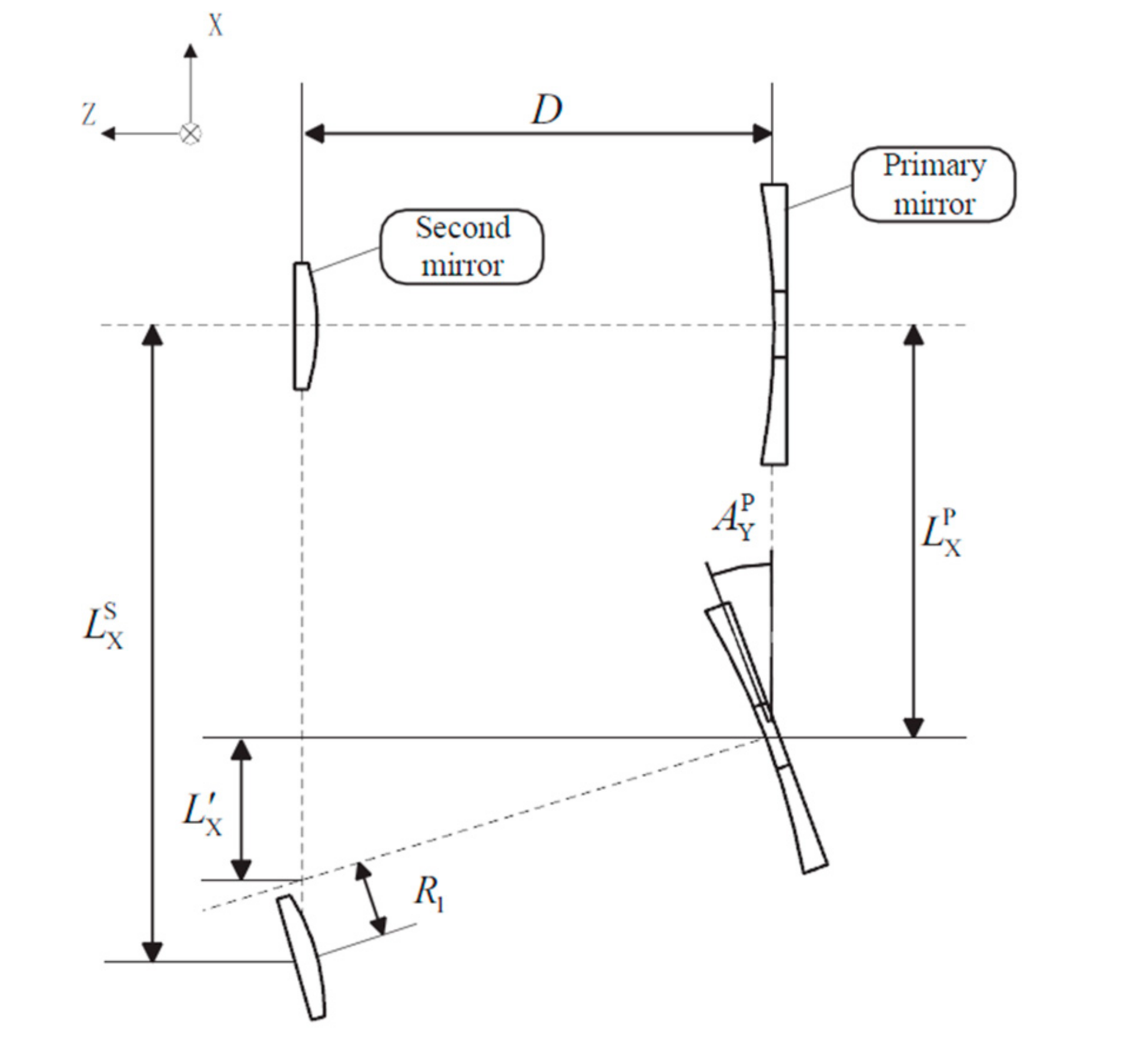
The displacements of the second mirror relative to the primary mirror include linear displacements of three degrees of freedom and angular displacements of three degrees of freedom. The calculation of the relative angular displacement is easy; it is the difference between the angular displacement of the second mirror and that of the primary mirror, but it changes the optical axis direction. The relative linear displacement is affected by the change of optical axis direction, and its calculation needs to add a quantity to the difference value. Taking the calculation of relative linear displacement along the X-axis direction as an example, the added quantity was analyzed, as shown in Figure 3.
From Figure 3, the relative displacement R1 can be obtained as shown in Equation (1).
in which represents the linear displacement of the second mirror along the X-axis; represents the linear displacement of the primary mirror along the X-axis; represents the angular displacement of the primary mirror along the Y-axis; and R1 represents the relative linear displacement along the X-axis.
Similarly, the relative linear displacement along the Y-axis can be obtained, as shown in Equation (2).
Since the Z-axis direction is the optical axis direction, the relative linear displacement along the Z-axis is not affected by the change of the optical axis direction, and it just consists of the difference between the displacement of the second mirror and that of the primary mirror. Then, the relative displacements can be summarized as shown in Equation (3).
2.3. Materials of the Componts
In terms of materials, to ensure that the connecting structure can isolate external loads and protect the camera, the materials need to have the characteristics of high specific stiffness and a small linear expansion coefficient. The higher specific stiffness means the stronger ability to withstand external loads and a higher lightweight ratio. The smaller linear expansion coefficient means a smaller deformation under thermal loads. Titanium alloys have been widely used in space cameras because of its high elastic modulus and small linear expansion coefficient [15]. Considering the manufacturing process and characteristics of the connecting structure, titanium alloy is adopted as its material. The materials used for the camera backplane, the satellite platform, and the connecting structure are summarized in Table 1.
3. Optimization Design of the Spaceborne Connecting Structure
3.1. Topology Optimization of Connecting Structures
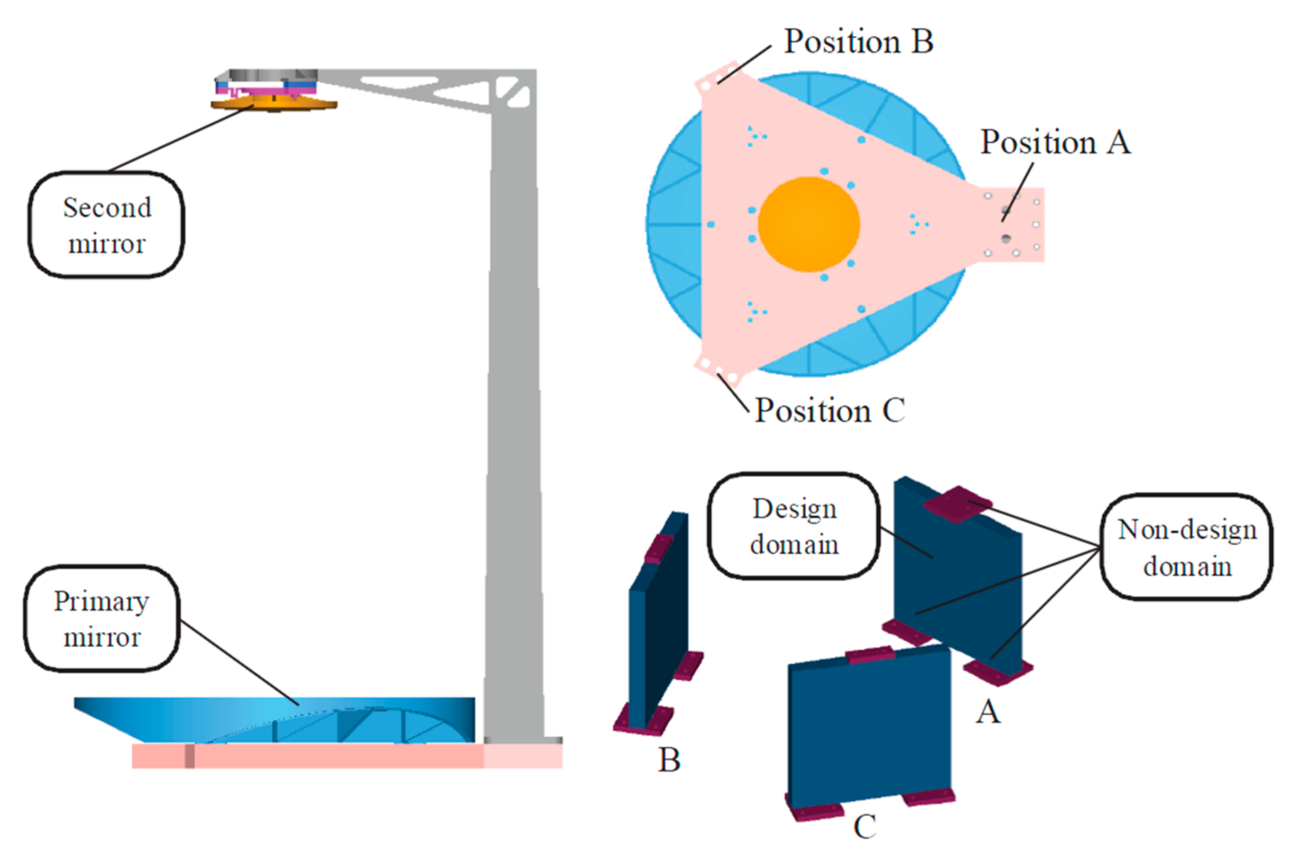
The finite element model of the camera was established by using Hypermesh software, as shown in Figure 4, with 145,225 elements and 16,642 nodes, including 81,894 hexahedral eight-node elements and 63,551 tetrahedral six-node elements. We fixed threaded holes at the bottom of the spaceborne connecting structures. In subcase 1, we applied the X-direction self-weight load of the camera. In subcase 2, we applied a 4 °C temperature rise load to all nodes. The top and bottom faces of the connecting structure were functional faces, which were connected to the camera and the satellite platform, respectively. Therefore, the top and bottom 5 mm thickness areas were set as a non-design domain, and the rest were set as a design domain.
The mass of the initial connecting structure is 2.4 kg. The support form of the optomechanical structure is a single pole support, and positions A, B, and C are the positions where the connecting structures are installed. The relative material densities of design domain elements are defined between zero and one. The elastic modulus of each element is introduced by using the Solid Isotropic Material with Penalty (SIMP) method [16]. Therefore, the topology optimization model is described as taking the relative material density of each element as a design variable, constraining the first-order nature frequency of the camera and the relative displacement of mirrors within design requirements, and the objective is to minimize the mass of the structure. A mathematical description of the topology optimization model is as shown in Equation (4).
in which and represent the relative displacement of the ith degree of freedom of mirrors under gravity load and temperature rise loads, respectively. When i is between 1 and 3, ; when i is between 4 and 6, .
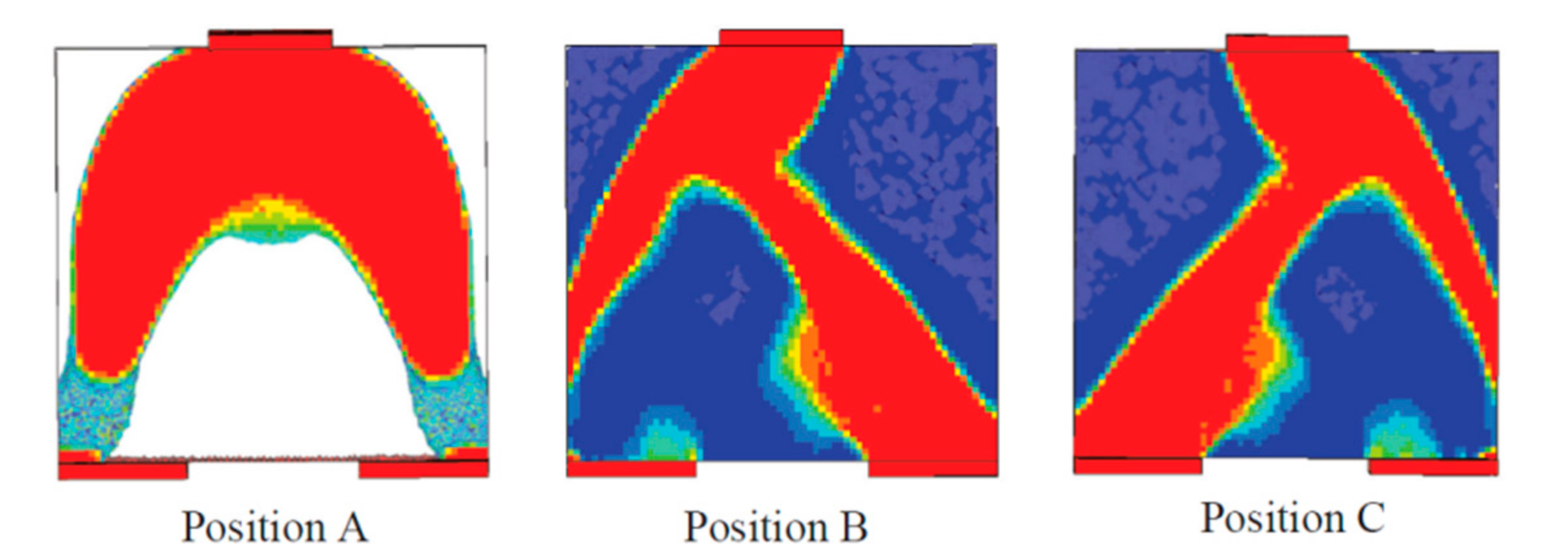
The topological optimization model was solved by using the Method of Moving Asymptotes (MMA) [17]. The optimal material distribution results are shown in Figure 5. The connecting structures presented typical bipod structures. The structure of position A is symmetrical, and some materials are removed from the bottom half of the bipod, which increases compliance greatly. The structures of position B and C are not symmetrical, and one end is thick, while the other end is thin. The connecting structures are in the form of mirror symmetry, which is consistent with the camera. Compared with the initial structure, a lot of materials are removed. The compliance of the structure is improved, and external loads transmitted into the camera from the bottom can be attenuated to a certain extent. In addition, the second mirror of the camera in this study is supported by a single pole, and the optomechanical structure is not circularly symmetrical, which results in the connecting structures in three positions not being the same. The results showed that the topology optimization design has carried out a reasonable material distribution to ensure the performance of the camera, rather than blindly and evenly distributing the material to three connecting structures.
3.2. Parametric Optimization Design
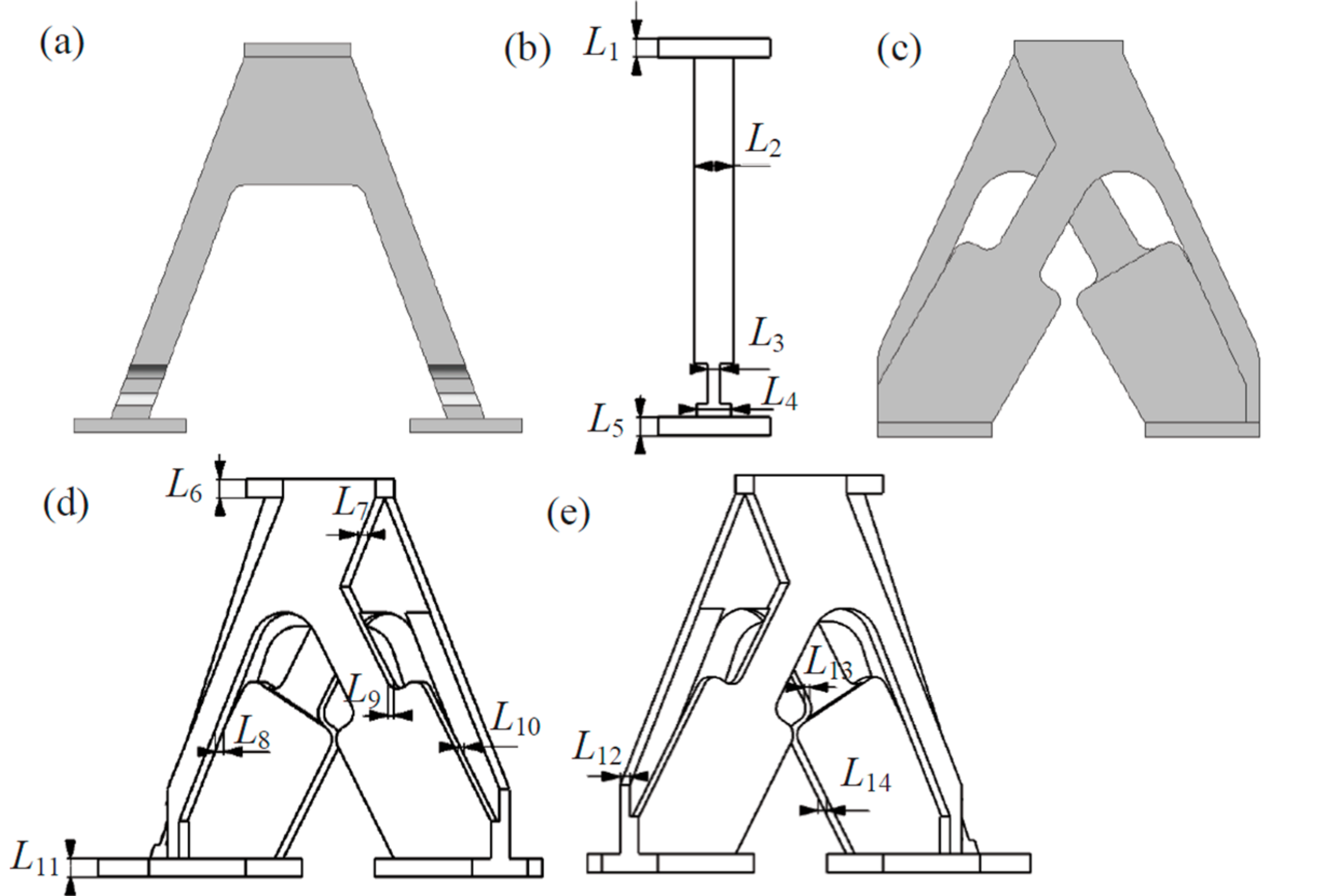
There are some unreasonable local features in the structure obtained by topology optimization due to numerical errors. So, it is necessary to combine with the actual manufacturing technology for processing. On the premise of ensuring the overall shape and sizes of the topology and in combination with the designer’s experience, the initial structure is trimmed to a regular shape that is easy to be manufactured. Some light-colored elements (the relative density is not 0 or 1) will inevitably exist in the topology optimization results, and these elements will be deleted by process treatment. Therefore, the performances of the structure after post-processing are not the same as the optimal result after topology. It is necessary to optimize its size parameters in detail. The geometric parametric model is shown in Figure 6. The structure of position A was parameterized, as shown in Figure 6b. L3 is the thinnest thickness of the structure, which provides great compliance for the structure. The structural parameters of position B and C were the same, as shown in Figure 6d,e. The outriggers of different thickness provide compliance for the structures, and on the premise of ensuring configurations, the thicknesses of each domain were parameterized as variables (L7–L10, L12–L14) that can be modified.
3.2.1. Sensitivity Analysis
In order to analyze the effect of size parameters on the camera performance, a sensitivity analysis was conducted by using a design of experiment method. Taking the geometric parameters L1–L14 as test factors, mechanical performances are obtained by finite element analysis, including mass, fundamental frequency, and mirror surface nodes displacement. The relative displacement between mirrors is calculated by using the equations proposed in Section 2.2.
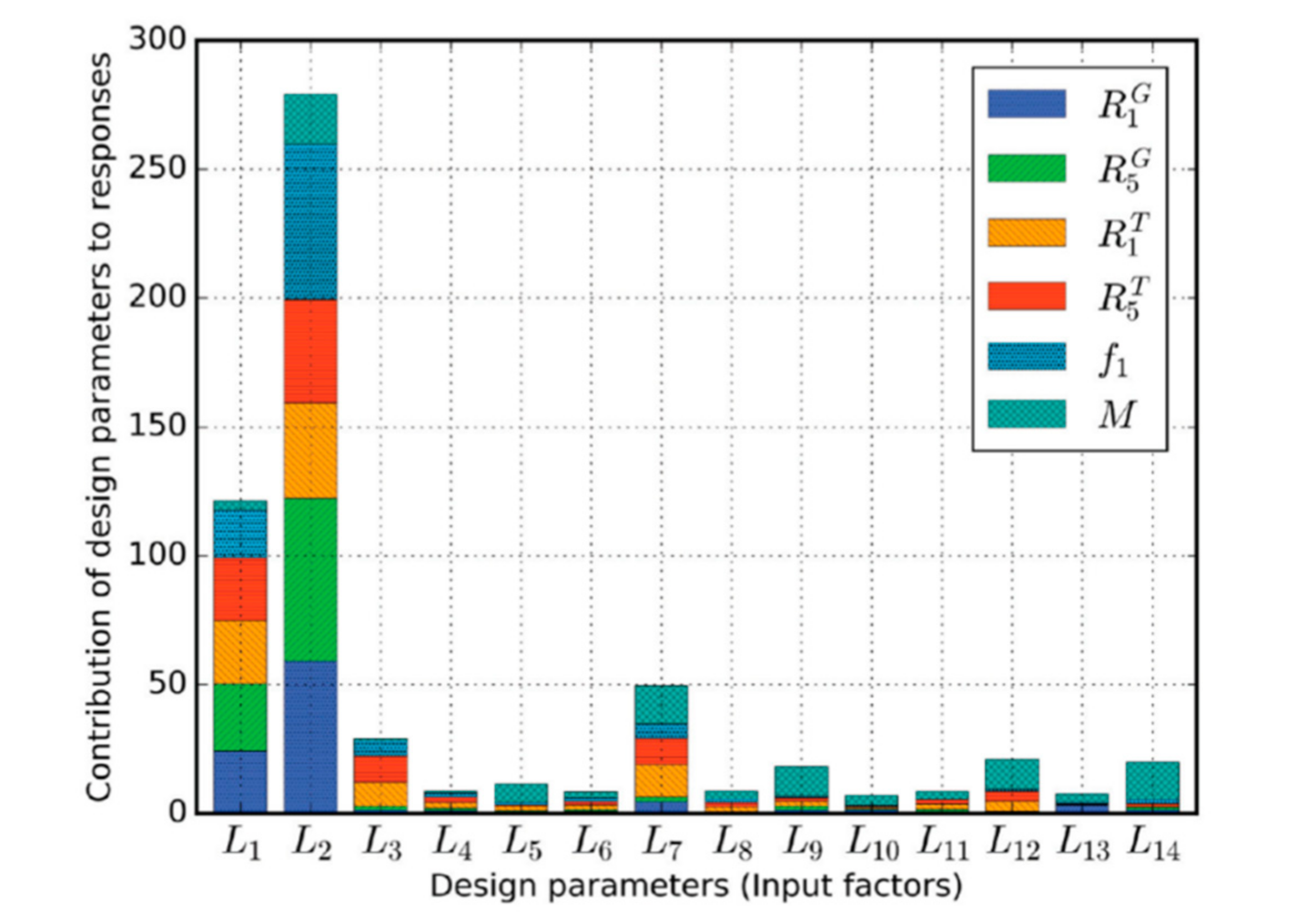
Commonly used sampling methods for design of experiment include the orthogonal arrays method, central composite method, Latin hypercube sampling method, etc. [18,19,20]. The Latin hypercube random sampling method was used to extract 100 size parameter combinations. Based on these data, a multi-variable one-order linear regression model was established. The coefficients of the multi-variables linear regression equation reflect the contribution of each test factor to the mechanical performance, which also represents the sensitivity of the size parameters to the performance response. Figure 7 shows the normalized percentage of the contributions, which can easily identify the key parameters.
3.2.2. Size Parameters Optimization
From the results of sensitivity analysis, L1, L2, L3, L7, L9, L12, and L14, are the key test factors, which have greater contributions to the performances of the camera. Therefore, we established the optimization model with these factors as design variables, the first-order nature frequency and the relative displacement between mirrors as design constraints, and the mass as an objective. The mathematical description of the optimization is as shown in Equation (5).
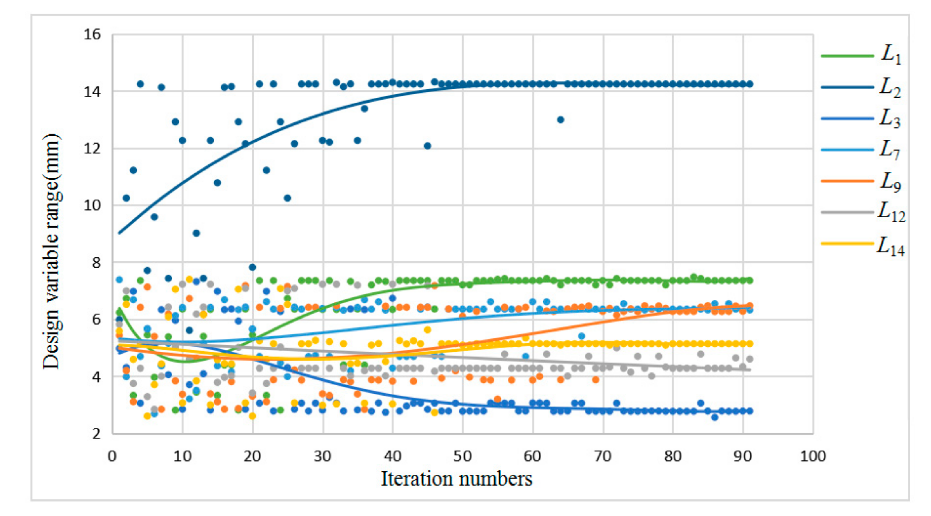
The non-dominated sorting genetic algorithm was used to solve the size parameter optimization model. Set its polarization size to 12, the number of generations to 20, the crossover probability to 0.9, the crossover distribution index to 10, the mutation distribution index to 20, and the initialization mode to random.
After 91 iterations, the model converges, as shown in Figure 8. The optimization results of the size parameters are summarized in Table 2. The maximum relative linear displacement is that in the X direction (R1), and the maximum relative angular displacement is that in the Y direction (R5). Those values before and after the optimization and other performances are summarized in Table 3. The results showed that the performances of the camera under the action of 1 g of gravity and 4 °C temperature rise loads all meet the design requirements, and the lightweight ratio of the structure reaches 54.2%.
4. Engineering Analysis and Performance Comparison
As a component of a space camera, the spaceborne connecting structure needs to have enough mechanical performances to withstand disturbance during ground transportation, rocket launching, and in-orbit operation. In order to verify the safety of the camera, it is necessary to conduct engineering analysis. First, we fixed the translation and rotation of screw hole element nodes at the bottom of the spaceborne connecting structure. Then, we analyzed the performances of the whole machine under static and dynamic loads, including the maximum displacement of the secondary mirror relative to the primary mirror, the wavefront error of the mirrors and the system, the mode information of the camera, and the acceleration response under random vibration load.
4.1. Static Analysis
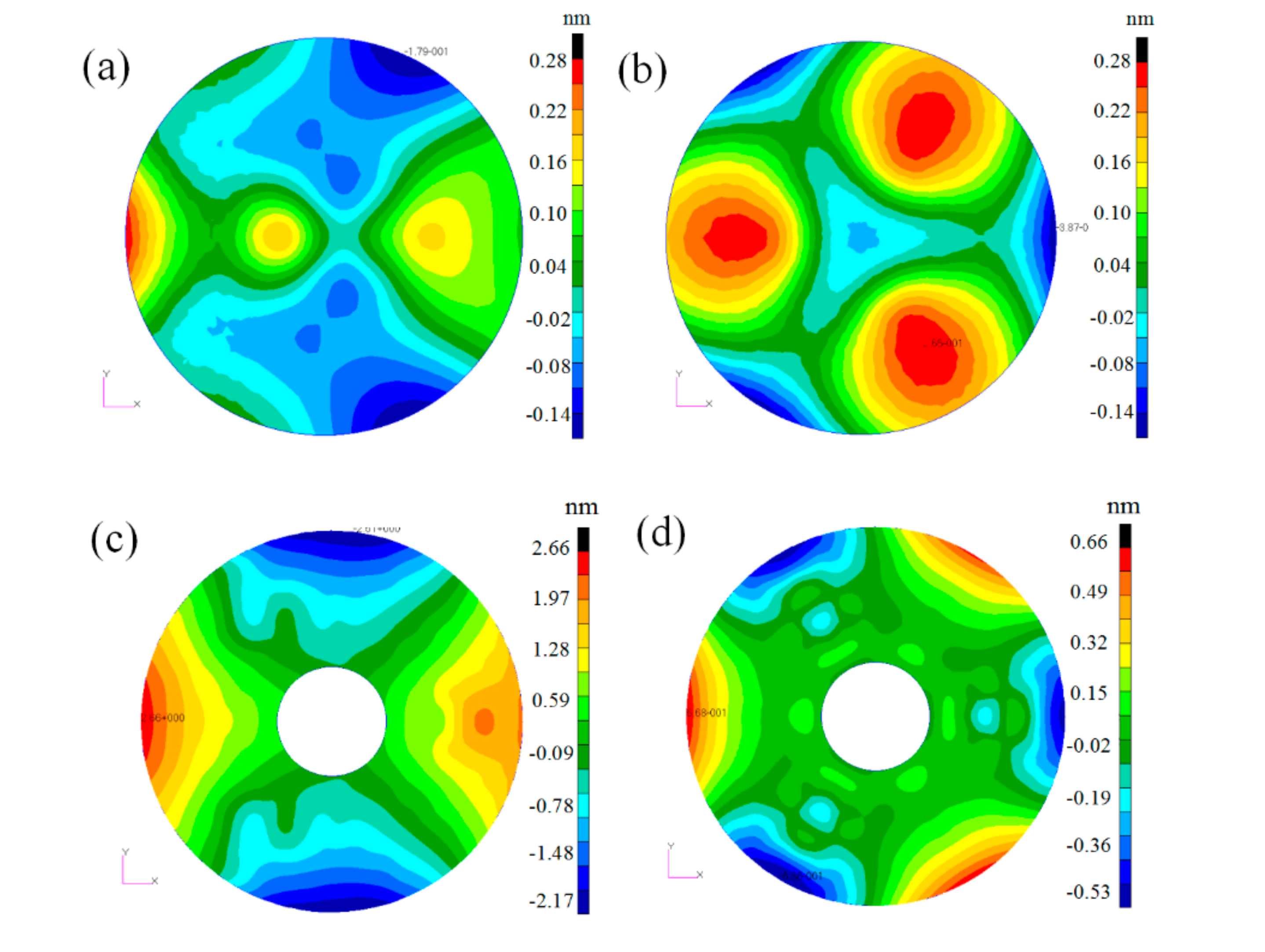
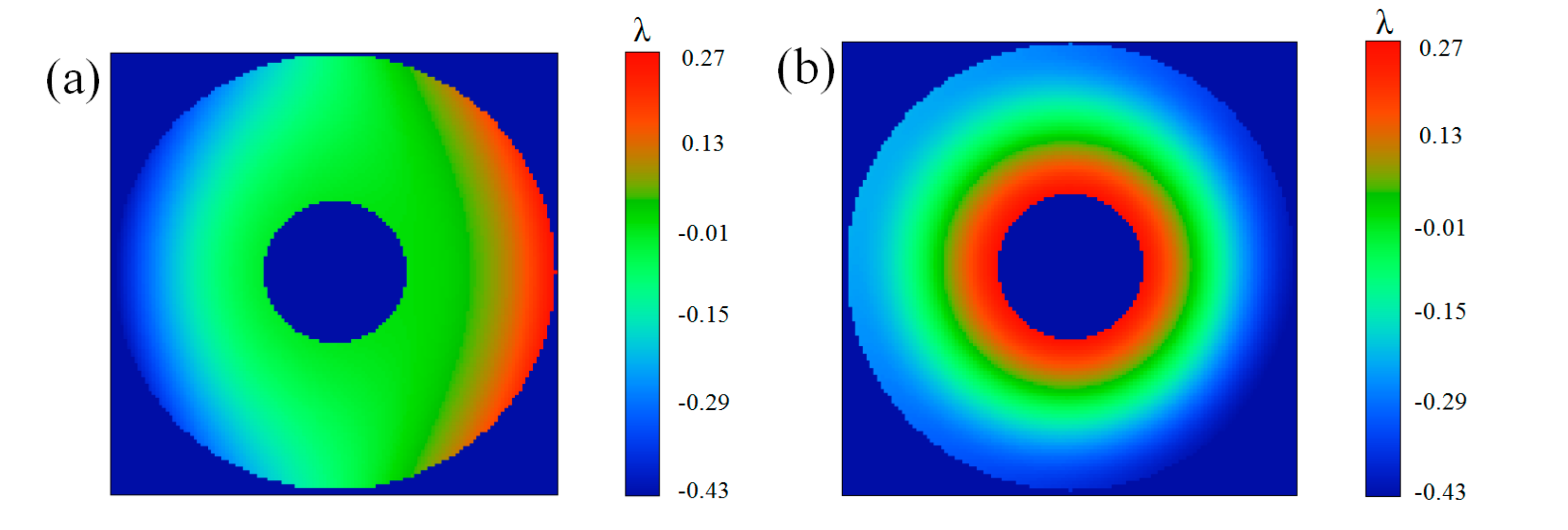
Static analysis is the performance analysis of the camera under the action of 1 g of gravity and 4 °C temperature rise loads. The maximum displacement of the secondary mirror relative to the primary mirror has been obtained in Section 3.2, as shown in Table 3. In addition, the displacement of the mirrors’ surface nodes can be fitted by the Zernike polynomial. After removing the rigid body displacement and the defocus terms of the mirrors, the RMS values of the mirrors’ surface deformation are calculated to evaluate the mirror quality under static loads. The surface deformation nephogram is shown in Figure 9. In order to evaluate the imaging quality of the camera, the rigid body displacements of the mirrors and surface deformation are input into the camera’s optical model, and the wavefront error of the system is obtained by using the ray-tracing method. The wavefront nephogram of the system is shown is Figure 10. The RMS values of the surface error and system wavefront error are summarized in Table 4.
From Figure 9, the surface accuracy of the mirrors is good. After removing the rigid body displacements and defocus, the RMS values of the mirror surface error are about 1 nm. From Figure 10, the wavefront error of the system is worst under 1 g of X-direction gravity, but it still meets the space application requirements, and the mirror performance and system performance are good under the temperature rise loads. The results showed that after installing the optimized connecting structure, the static performances of the system meets the design requirements.
4.2. Dynamic Analysis
In order to better verify the dynamic mechanical performance of the camera, random analysis of the camera was carried out. From Section 3.2 in Table 3, the fundamental frequency meets the design requirements, indicating that the dynamic stiffness of the camera is high enough to avoid resonance with a rocket carrier under the action of low-frequency sinusoidal excitation. The test conditions of random vibration are given by the technicians of rocket design, as shown in Table 5. The dynamic analysis showed that the node with the largest acceleration excitation response is located at the edge of the primary mirror, which is set as the sampling point. The acceleration responses of the sampling point in the X, Y, and Z directions are summarized in Table 6. The results show that the direction corresponding to the maximum response of the sampling point is the X direction (vertical to the optical axis), and the amplification factor is 4.71, which meets the mechanical performance requirements. It demonstrates that the dynamic performances of the system meet the engineering application.
4.3. Performance Comparison
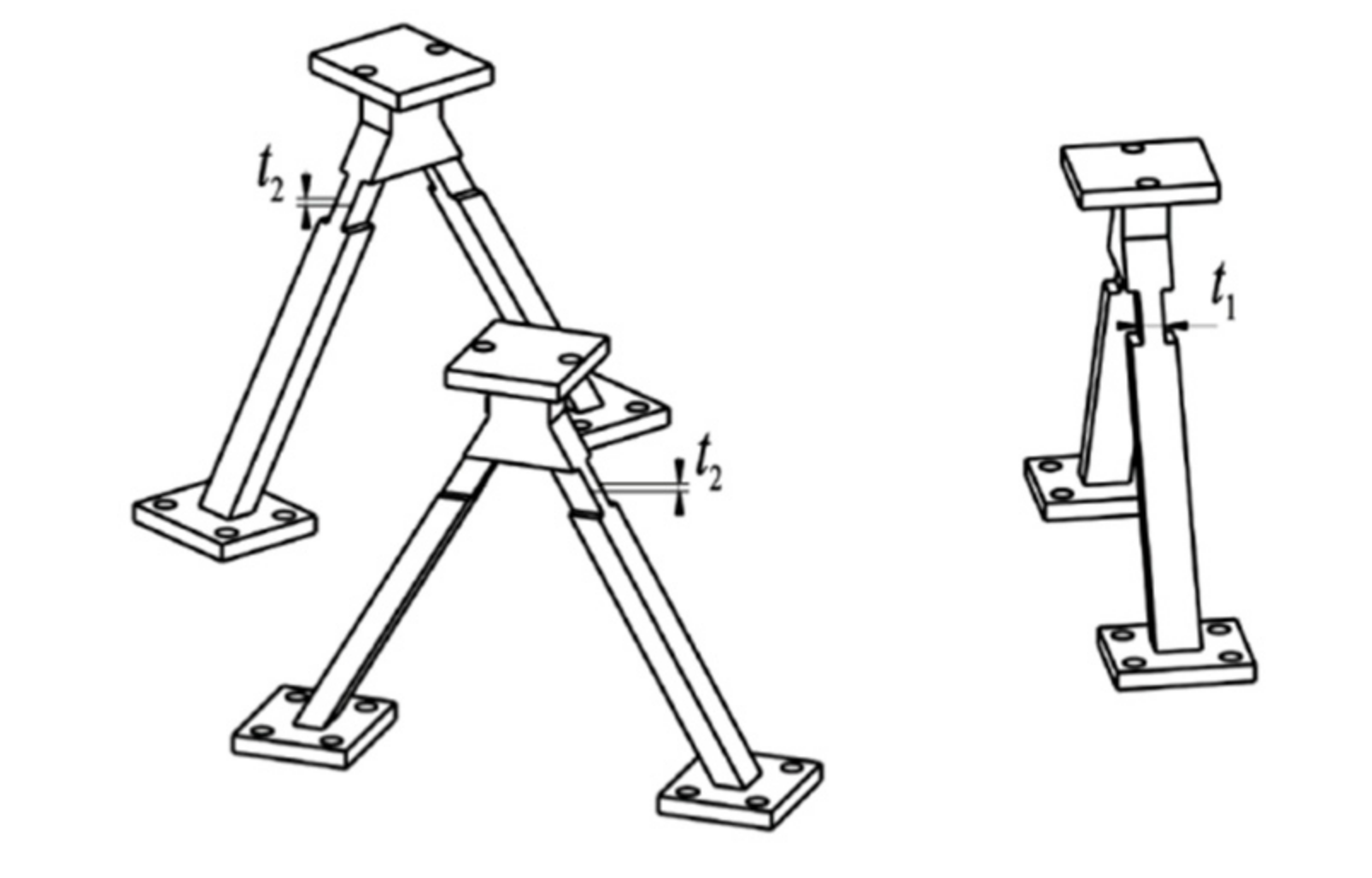
In order to further evaluate the effect of the optimization method, a traditional bipod support structure (as shown in Figure 11) is selected to contrast with the structures designed in this paper. The camera is mounted using the traditional structure in the same assembling method. Positions A, B, and C adopt the same configuration but with different flexible sizes, which are optimized by using size parametric optimization. t1 and t2 are set as the design variables. The objective and constraint functions are the same as those functions in Equation (5). After the convergence of optimization iteration, the optimized t1 and t2 are 12.5 mm and 9.8 mm, respectively. The optimization results of all responses are summarized in Table 7.
The optimization results of the traditional structure show that after installing the traditional support structure, the first natural frequency meets the performance requirements, but the relative displacements between mirrors exceed the design requirements. In contrast, R1 and R5 for the optimized spaceborne connecting structure optimized in this paper are 35% and 42% smaller compared with the traditional structure under the action of 1 g of gravity. They are 43% and 29% smaller under the action of a temperature rise of 4 °C. Furthermore, the optimized connecting structures in this paper have a higher lightweight ratio. These demonstrate the effectiveness of the design method presented in this paper.
5. Conclusions
This paper presents an optimization design method for designing spaceborne connecting structures. Drift of line of sight (LOS) is the movement of an image point on the image plane under external loads. In order to meet the design requirements of the camera’s LOS drift under 1 g of gravity and a temperature rise load, the LOS drift was qualitatively analyzed. The main factor that affects the LOS drift is the relative displacements between the secondary mirror and primary mirror. The specific expressions of the relative displacements between mirrors were derived. In order to obtain the optimal configuration of the spaceborne connecting structure, a topology optimization model was established with the mass as the objective and the fundamental frequency and relative displacements between mirrors as constraints. The topology optimization model was solved by using MMA. Based on the topology optimization results, the sensitivity analysis of size parameters was carried out. The analysis result showed that the size parameters have an obvious influence on the performance of the system. To obtain the optimal size parameters combination, a size parameter optimization model was established, and it was solved by using GA. In order to further evaluate the effect of the optimization, engineering analysis was carried out. The performance was compared with the traditional flexible structure after size parameter optimization. The results showed that the camera mounted by the designed connecting structure in this paper has better comprehensive performance. The relative linear displacements and angular displacements between mirrors are within 10 μm and 10″ respectively, which meet the design requirements, and the lightweight ratio of the connecting structures reached 54%, which verifies the effectiveness of the proposed optimization design method.
In this paper, the relative displacements between mirrors were analyzed in detail, which is the main factor affecting the camera’s LOS drift. By integrating the relative displacements into the optimization design model of the spaceborne connecting structures, effective optimization results were obtained. If the other structures in the optomechanical system have an obvious influence on the camera’s LOS drift, this method can also be used for their optimization design, which can significantly improve the LOS stability and lightweight ratio of the structure. However, if a structure in the optomechanical system has little effect on the LOS drift, it should consider other targeted design methods and conduct specific analysis. The camera’s system performances also include other optical metrics such as optical transfer function and energy distribution. In the future, if the optical transfer function under external loads can be integrated in the optomechanical structure optimization, the design will be more effective.
Author Contributions
Conceptualization, M.S. and L.Z.; methodology, M.S., L.Z. and X.J.; software, L.Z.; validation, M.S., L.Z. and X.J. writing—original draft preparation, M.S.; writing—review and editing, M.S.; supervision, M.S.; project administration, L.Z.; funding acquisition, L.Z. All authors have read and agreed to the published version of the manuscript.
Funding
This research was supported by the National Key Research and Development Program from Ministry of Science and Technology of the People’s Republic of China under Grant No. 2016YFB0500904.
Conflicts of Interest
The authors declare no conflict of interest.
References
- Stahl, P.H.; Postman, M.; Mosier, G.; Scott Smith, W.; Blaurock, C.; Ha, K.; Stark, C.C. AMTD: Update of engineering specifications derived from science requirement for future UVOIR space telescope. Proc. SPIE 2014, 9143. [Google Scholar] [CrossRef] [Green Version]
- Feinberg, L.; Cohen, L.; Dean, B.; Hayden, W.; Howard, J.; Keski-Kuha, R. Space telescope design considerations. Opt. Eng. 2012, 51, 011006. [Google Scholar] [CrossRef]
- Murthy, K.; Shearn, M.; Smiley, B.D.; Chau, A.H.; Levine, J.; Robinson, M.D. Skysat-1: Very high-resolution imagery from a small satellite. Proc. SPIE 2014, 9241, 9241E. [Google Scholar]
- Kruse, F.A.; Baugh, W.M.; Perry, S.L. Validation of digital globe world view-3 earth imaging satellite shortwave infrared bands for mineral mapping. J. Appl. Remote Sens. 2015, 9, 096044. [Google Scholar] [CrossRef]
- Keas, P.; Brewster, R.; Guerra, J.; Lampater, U.; Karcher, H.; Teufel, S.; Wagner, J. SOFIA telescope modal survey test and test-model correlation. Proc. SPIE 2010, 7738, 77380K. [Google Scholar]
- Weingrod, I.; Chou, C.Y.; Holmes, B.; Hom, C.; Wes Irwin, J.; Lindstorm, O.; Lopez, F. Design of bipod flexure mounts for the iris spectrometer. Proc. SPIE 2013, 8836, 88360Q. [Google Scholar]
- Riva, M.; Moschetti, M. Integrated optomechanical structural optimization through coupling of sensitivity matrixes. Proc. SPIE 2016, 10012, 10012D. [Google Scholar]
- Kurita, M.; Ohmori, H.; Kunda, M. Light-weight telescope structure optimized by genetic algorithm. Proc. SPIE 2010, 7733, 7733E. [Google Scholar]
- Chen, Y.-C.; Huang, B.-K.; You, Z.-T.; Chan, C.-Y.; Huang, T.-M. Optimization of lightweight structure and supporting bipod flexure for a space mirror. Appl. Opt. 2016, 55, 10382–10391. [Google Scholar] [CrossRef] [PubMed]
- Park, K.S.; Chang, S.Y.; Youn, S. Topology optimization of the primary mirror of a multi-spectral camera. Struct. Multidisc. Optim. 2003, 25, 46–53. [Google Scholar] [CrossRef]
- Hu, R.; Liu, S.; Li, Q. Topology-optimization-based design method of flexures for mounting the primary mirror of a large-aperture space telescope. Appl. Opt. 2017, 56, 4551–4560. [Google Scholar] [CrossRef] [PubMed]
- Malacara, D.; Malacara, Z. Handbook of Optical Design, 3rd ed.; CRC Press: Boca Raton, FL, USA, 2013; pp. 199–206. [Google Scholar]
- Chen, Z.; Zhang, R.; Chen, Z.; Yang, S.; Hu, Q. Experiment and modal analysis on the primary mirror structure of space solar telescope. Proc. SPIE 2006, 62654, 62654B. [Google Scholar]
- Doyle, K.; Genberg, V.; Michels, G. Integrated Optomechanical Analysis, 2nd ed.; SPIE Press Book: Bellingham, WA, USA, 2012; pp. 178–189. [Google Scholar]
- Peters, M.; Leyens, C. Aerospace and space materials. Mater. Sci. Eng. 2009, 3, 1–11. [Google Scholar]
- Rietz, A. Sufficiency of a finite exponent in SIMP (power law) methods. Struct. Multidisc. Optim. 2014, 21, 159–163. [Google Scholar] [CrossRef]
- Svanberg, K. The method of moving asymptotes—A new method for structural optimization. Int. J. Numer. Meth. Eng. 2010, 24, 359–373. [Google Scholar] [CrossRef]
- Owen, B.A. Orthogonal arrays for computer experiments, integration and visualization. Stat. Sin. 1992, 2, 439–452. [Google Scholar]
- Hang, Y.; Qu, M.; Ukkusuri, S. Optimizing the design of a solar cooling system using central composite design techniques. Energy Build. 2011, 43, 988–994. [Google Scholar] [CrossRef]
- Stein, M. Large sample properties of simulations using Latin hypercube sampling. Technometrics 1987, 29, 143–151. [Google Scholar] [CrossRef]
Figure 1.
Movement of an image on an image plane. (a) Movement in the direction perpendicular to the optical axis. (b) Movement in the direction parallel to the optical axis.
Figure 1.
Movement of an image on an image plane. (a) Movement in the direction perpendicular to the optical axis. (b) Movement in the direction parallel to the optical axis.

Figure 2.
Relationship between the connecting structure, the camera, and the installation position.

Figure 3.
Relative linear displacement of mirrors along the x-axis direction.

Figure 4.
Finite element model of the camera and the initial connecting structure.

Figure 5.
Results of the topology optimization. The relative density of red elements is 1, which represents the elements that should be retained. The relative density of the other color elements is less than 1, which represents the elements that can be removed.
Figure 5.
Results of the topology optimization. The relative density of red elements is 1, which represents the elements that should be retained. The relative density of the other color elements is less than 1, which represents the elements that can be removed.

Figure 6.
Conceptual configuration of connecting structures. (a,c) Geometry model. (b,d,e) Parametric model.
Figure 6.
Conceptual configuration of connecting structures. (a,c) Geometry model. (b,d,e) Parametric model.

Figure 7.
Contributions of parameters to each performance.

Figure 8.
Iteration history of design variables.

Figure 9.
Mirror surface nephogram after removing rigid body displacements and defocus. (a,c) Nephogram of the secondary mirror and primary mirror under 1 g of gravity, respectively. (b,d) Nephogram of the secondary mirror and primary mirror under 4 °C temperature rise load, respectively.
Figure 9.
Mirror surface nephogram after removing rigid body displacements and defocus. (a,c) Nephogram of the secondary mirror and primary mirror under 1 g of gravity, respectively. (b,d) Nephogram of the secondary mirror and primary mirror under 4 °C temperature rise load, respectively.

Figure 10.
System wavefront nephogram. (a) 1 g of gravity in the X direction. (b) 4 °C temperature rise load (λ = 550 nm).
Figure 10.
System wavefront nephogram. (a) 1 g of gravity in the X direction. (b) 4 °C temperature rise load (λ = 550 nm).

Figure 11.
Conventional flexure configurations.


Table 1.
Material properties of the components.
| Components | Materials | Elastic Modulus (109 Pa) | Poisson Ratio | Density (g/cm3) | Thermal Expansion Coefficient (10−6/K) |
|---|---|---|---|---|---|
| Camera backplane | SiC | 420 | 0.17 | 3.16 | 2.5 |
| Connecting structure | Ti alloy | 109 | 0.34 | 4.44 | 9.1 |
| Satellite platform | Carbon fiber composite | 90 | 0.30 | 180 | 0.1 |
Table 2.
Size parameters before and after parametric optimization.
| Design Variables | L1 | L2 | L3 | L7 | L9 | L12 | L14 |
|---|---|---|---|---|---|---|---|
| Initial values/(mm) | 5.0 | 10.0 | 5.0 | 5.0 | 5.0 | 5.0 | 5.0 |
| Optimized values/(mm) | 7.3 | 14.2 | 2.8 | 6.3 | 6.3 | 4.3 | 5.1 |
Table 3.
Camera performance before and after the optimization of a spaceborne connecting structure.
| Response | ||||||
|---|---|---|---|---|---|---|
| Initial values | 9.0 | 7.3 | 6.1 | 6.0 | 130 | 2.4 |
| Optimized values | 9.8 | 9.7 | 4.3 | 6.5 | 112 | 1.1 |
| Requirement | ≤10.0 | ≤10.0 | ≤10.0 | ≤10.0 | ≥100 | Min |
Table 4.
Root mean square (RMS) values of surface error of mirrors and system wavefront error (λ = 550 nm).
Table 4.
Root mean square (RMS) values of surface error of mirrors and system wavefront error (λ = 550 nm).
| Wavefront Error RMS | Primary Mirror (nm) | Secondary Mirror (nm) | System (λ) |
| X-Gravity | 1.11 | 0.08 | 0.13 |
| 4 °C temperature rise | 0.21 | 0.10 | 0.02 |
Table 5.
Random vibration test conditions.
| Random Vibration Input Conditions (X, Y, Z) | ||||||
|---|---|---|---|---|---|---|
| Frequency range/Hz | 20 | 40 | 500 | 700 | 1200 | 2000 |
| Power spectral density (g2/Hz) | 0.001 | 0.01 | 0.01 | 0.02 | 0.02 | 0.004 |
| Root mean square (g) | 4.67 | |||||
Table 6.
Results of random response analysis.
| Direction | X | Y | Z |
|---|---|---|---|
| The results of random vibration analysis/Hz | 22.02 | 20.73 | 20.18 |
| Amplification | 4.71 | 4.43 | 4.32 |
Table 7.
Performance comparisons of different flexure mountings.
| Response | ||||||
|---|---|---|---|---|---|---|
| The traditional structure | 15.1 | 16.7 | 7.3 | 9.1 | 121.6 | 1.2 |
| Optimized structure in this paper | 9.8 | 9.6 | 4.2 | 6.5 | 112.1 | 1.1 |
| Requirements | ≤10.0 | ≤10.0 | ≤10.0 | ≤10.0 | ≥100 | Min |
Publisher’s Note: MDPI stays neutral with regard to jurisdictional claims in published maps and institutional affiliations. |
© 2020 by the authors. Licensee MDPI, Basel, Switzerland. This article is an open access article distributed under the terms and conditions of the Creative Commons Attribution (CC BY) license (http://creativecommons.org/licenses/by/4.0/).
Share and Cite
MDPI and ACS Style
Shao, M.; Zhang, L.; Jia, X. Optimization Design of the Spaceborne Connecting Structure for a Lightweight Space Camera. Appl. Sci. 2020, 10, 8249. https://0-doi-org.brum.beds.ac.uk/10.3390/app10228249
AMA Style
Shao M, Zhang L, Jia X. Optimization Design of the Spaceborne Connecting Structure for a Lightweight Space Camera. Applied Sciences. 2020; 10(22):8249. https://0-doi-org.brum.beds.ac.uk/10.3390/app10228249
Chicago/Turabian StyleShao, Mengqi, Lei Zhang, and Xuezhi Jia. 2020. "Optimization Design of the Spaceborne Connecting Structure for a Lightweight Space Camera" Applied Sciences 10, no. 22: 8249. https://0-doi-org.brum.beds.ac.uk/10.3390/app10228249
Note that from the first issue of 2016, this journal uses article numbers instead of page numbers. See further details here.