Article

Electrical and Microwave Characterization of Thermal Annealed Sewage Sludge Derived Biochar Composites

1
DET, Politecnico di Torino, C.so Duca degli Abruzzi 24, 10129 Torino, Italy
2
DISAT, Politecnico di Torino, C.so Duca degli Abruzzi 24, 10129 Torino, Italy
3
BioForceTech Corporation, 1400 Radio road, Redwood City, CA 94065, USA
*
Author to whom correspondence should be addressed.
Submission received: 30 December 2019 / Revised: 3 February 2020 / Accepted: 12 February 2020 / Published: 16 February 2020
(This article belongs to the Special Issue Biochar: Productions, Properties and Applications)

Abstract

:
Ever-increasing proportions of sewage sludge are being generated due to increases in population and urbanization. As a result, the disposal of sewage sludge for use as manure and for other agricultural applications is not sufficient. The use of biochar derived from sewage sludge as a substitute to other carbon fillers was analyzed by performing electrical and morphological characterization. The electrical and microwave characterization of composites filled with sludge biochar was performed. Thermal annealing of biochar makes it conductive and suitable for a variety of electrical and microwave applications. Composite samples of a thickness of 4 mm with 20 wt.% of sludge biochar provided a shielding effectiveness value of almost 10 dB.

1. Introduction

Wastewater streams management is one of the most relevant issues of any large human settlement [1]. The final residue from every wastewater stream treatment is represented by several forms of sludge [2]. Over the last decade, the amount of sludge has increased continuously and significantly due to the rapid population growth of cities. The disposal of sewage sludge is a hard task due to its high composition variability and government regulations [3]. Traditionally, sewage sludge has been used in agriculture as fertilizers [4,5] and for landscape applications [6,7]. Nonetheless, direct use of sewage sludge involves several issues due to heavy metal accumulation [8]. This is caused by both residue accumulation during water use and treatments with coagulation and flocculation agents. The most widely used coagulation and flocculation agents are iron and aluminum sulphate [9,10], which are retained in the sludge. The removal of these metals is quite challenging [11,12], expensive and not economically profitable.
Nonetheless, several studies have used the treated sludge without removing metals for catalytic applications. Recently, thermally hydrolyzed sludge was used as an efficient catalyst for intra- and inter-molecular esterification processes [13,14]. Sludge catalytic activity could be magnified by pyrolytic processes that increase the inorganic content through a radical degradation of organic matter. Pyrolyzed sludge was used as a Fenton catalyst for water purification [15] and for the realization of energy storage systems (see, e.g., [16]). Furthermore, sludge derived biochar was used as an adsorbent for wastewater purification [17], promoting a virtuous circular reuse of wastewater streams.
In the field of composites (see, e.g., [18,19,20]), sludge derived biochar has been used for the production of concrete- [18] and poly(ethylene)-based composites [21] to enhance the polymer hosts’ mechanical and thermal properties. The electrical properties of biochar derived from vegetation were reported in [22,23,24]. Accordingly, in this study, we report the electrical and morphological characterization of sludge derived biochar. DC characterization of thermally annealed biochar and non-thermally annealed biochar was performed, and it was found that the thermally annealed biochar had better electrical performance. Consequently, composite samples of thermally annealed biochar were fabricated, and microwave characterization in a rectangular waveguide was performed. Values of the shielding effectiveness (SE) were extracted from the measured transmission loss.

2. Materials and Methods

2.1. Materials

Human excrement collected through the sewerage system is referred to as sewage sludge. It was converted into Class-B biosolids by anaerobic digestion and subsequently converted into Class-A biosolids by processing it through the BioDryer, a drying process developed by Bioforcetech Corporation. These biosolids were then turned into biochar through pyrolysis.

2.2. Methods

For the conversion of raw human excrement and other organic matter collected through the sewerage system into Class-A biosolids, a bio-drying process was used. In this process, the weight of biodegradable waste was reduced through heating in the initial stages of composting. The process was sustainable since biological heat generated by aerobic degradation was used in heating to dry the sludge. As a second step, pyrolysis was used to turn the biosolids into biochar. Pyrolysis involved the heating of organic matter in the absence of oxygen, at 650°C with a residence time of 20 min. This process was sustainable and eco-friendly since no extra carbon and other harmful gases were left in the environment.
The pyrolyzed biochar acquired from Bioforcetech Corporation was further thermally treated using a vertical furnace and a quartz reactor, at a heating rate of 15 °C/min and kept at 1000 °C for 30 min in an argon atmosphere. A Raman analysis was performed on the non-thermally treated and thermally treated biochar with a Renishaw spectrometer with excitation energy of 532 nm. A 50× objective was used for the characterization. The spectral resolution of the spectrometer was 2–3 cm−1 and laser power was kept well below 1 mW to avoid damage. Spectra were processed by removing fluorescence and normalized on IG peak of carbon.
The morphology of biochars were investigated using a Field Emission Scanning Electrical Microscopy (FESEM, Zeis SupraTM 40). Energy Dispersive X-Ray analysis (EDX, Oxford Inca Energy 450) was used to study the elements present in the biochars under study.
A measurement setup previously validated in [22,23,25] for DC powders’ characterization was used, which is similar to the setup adopted in [26,27,28,29,30,31,32,33,34]. As shown in Figure 1, the instrument is comprised of two solid copper cylinders, 30 mm in diameter and 5 cm in length, and encapsulated in a hollow Plexiglas cylinder with a nominal inner diameter of 30 mm in the case of powders’ electrical characterization. In this configuration, the inner diameter is slightly larger so that it is possible to force the copper rods inside the Plexiglas cavity and the upper rod can slide inside the hollow cylinder during measurement. This arrangement creates an internal chamber between the two cylinders where the carbon powder can be inserted. The values obtained with this setup provide an estimated conductivity with a margin of error ranging from 15% to 20%.
The electrical resistance of the powders was measured at increasing loads (up to 1000 bar) applied by a hydraulic press (Specac Atlas Manual Hydraulic Press 15T). Electrically insulating sheets were placed between the conductive cylinders and the load surfaces in order to ensure that the electrical signal passed through the sample. The resistance of the carbon fillers was measured using an Agilent 34401A multimeter. From the values of the resistance, R, the conductivity, σ, can be calculated by:
σ = L R A
where L is the length of the cylinder and A is the section.
The shielding effectiveness, which is a measure of the reduction of the electromagnetic field propagating in a medium, can be obtained in several ways: for example, from the measured permittivity of the medium [35] or from the measured scattering parameter in a waveguide [36].
There are two main contributions to the shielding effectiveness, namely, dissipation loss, LD, and mismatch loss, LM [37]:
S E = L D + L M
where LM and LD can be calculated from the scattering parameters as:
L M = 10   l o g 10 ( 1 | S 11 | 2 )
L D = 10 l o g 10   ( | S 21 | 2 1 | S 11 | 2 )
The composite samples were measured in a rectangular waveguide structure, as shown in Figure 2. Samples of specified dimensions needed to be fabricated to fit in the waveguide structure. For this purpose, appropriate molds made of silicone were first fabricated from a 3D-printed master mold. Silicone molds are reusable and flexible. This helps in easy extraction of composite samples once they are polymerized. For the fabrication of the composite samples for measurements in the waveguide, a pre-weighted quantity of biochar filler was mixed in epoxy resin using a mechanical mixer. A hardener was added to the mixture to help in polymerization. This mixture was then transferred to the silicone molds. Once polymerized, the samples were extracted from the molds for measurement.
After the samples were produced, they were fit into a metallic holder, which was connected between the ends of a rectangular waveguide. The rectangular waveguide was the WR 90, which operates in the X-band (8 GHz to 12 GHz) of the microwave frequency spectrum. The internal dimensions of the waveguide were 22.86 mm × 10.16 mm. The Vector Network Analyzer (VNA) used for measurements of the scattering parameters was Agilent E8361A. The measurement setup is shown in Figure 3. The ports of the VNA were connected to the waveguides by means of coaxial to waveguide adapters. A standard procedure for waveguide calibration was adopted before the measurements were collected, which consisted of reflection, transmission and isolation (often omitted). The measurements were performed using calibration standards (short, load and through).
Measurements of scattering parameters performed with an empty waveguide showed almost lossless transmission. Subsequent measurements of biochar composites with 10 wt.% and 20 wt.% biochar were performed with a pristine resin sample. From the measured transmission loss (S21), the shielding effectiveness values were evaluated as S E = 10   L o g ( S 21 ) .

3. Results

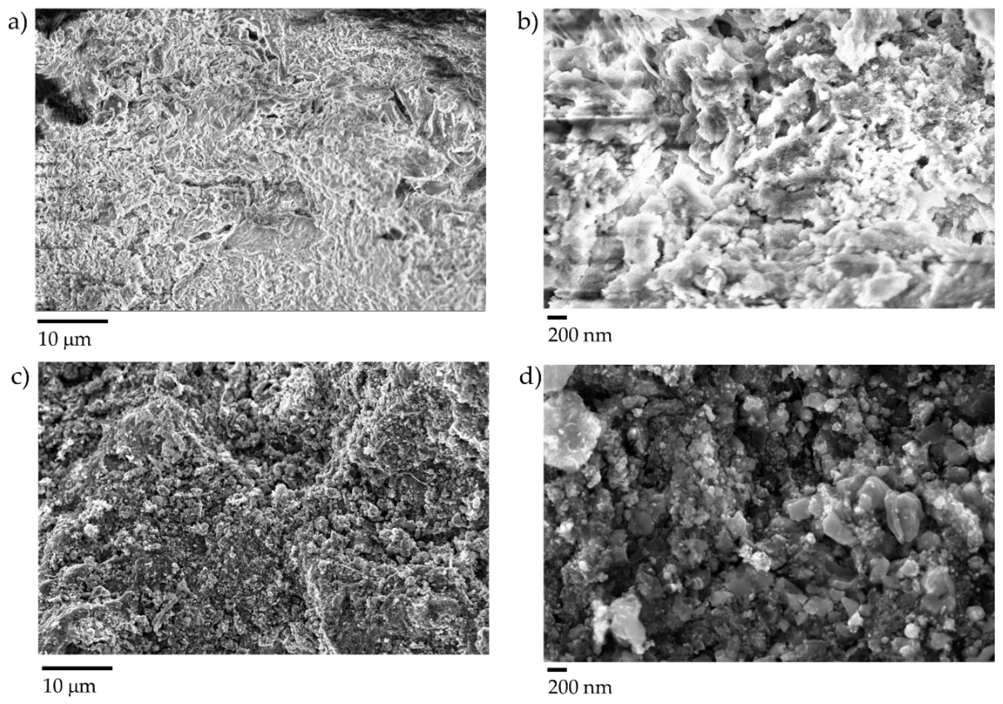
3.1. Morphological Characterization of Sludge Derived Biochar

Raman analysis (see Figure 4) on non-thermal annealed biochar shows a high degree of fluorescence. Raman spectra appear not quite uniform at different points of the sample. This could be due to a nonuniform carbonization process at low temperatures (650 °C for 20 min). The thermally annealed biochar (1000 °C for 30 min) shows sharp Raman spectra with narrow D and G peaks. Spectra collected at different points show similar shapes in the thermal annealed sample, which supports a uniform carbonization process. Sharp D and G peaks from high thermal temperature annealing are due to the crystallization process of the carbon structure.
Figure 5 shows the FESEM characterization of non-thermal annealed sludge biochar and thermal annealed sludge biochar.
Non-thermal annealed sludge biochar has a slightly rough surface on both a large and reduced scale. Using a high magnification, grains with an average dimension of around 1 μm can be observed. Thermal annealed sludge biochar has a very rough surface with similar grains. In this case, the grains are smaller and more defined with respect to the carbonaceous matrix. This could be explained by the results of the EDX analysis shown in Figure 6 and in Table 1. This analysis maps an area of around 60 × 60 µm (mapping images).
Thermal annealing considerably reduced the carbon content of the sludge derived biochar from 55.20 wt.% down to 39.70 wt.%. This was unusual because, generally, with the increase of pyrolytic temperatures, the carbon content increases [38]. In this particular case, we suppose that the high starting inorganic content promoted a drastically radical degradation of organic matter with a concentration of inorganic species [39]. This explains the detection of elements such as Ti, Fe, Zn and the increase of all the others with the exception of halides, which could form volatile compounds dragged away by the inert carrier gas flux [40].
FESEM analysis was performed on the composites with 10 wt.% and 20 wt.% of biochar in order to study the biochar dispersion. The results are shown in Figure 7. A higher content of biochar can be seen in the composite with 20 wt.% biochar as compared to the composite with 10 wt.%. In both cases, a good dispersion of the filler was observed in the different sample portions analyzed. Furthermore, a rise in inorganic content led to a more granular structure in the composites.

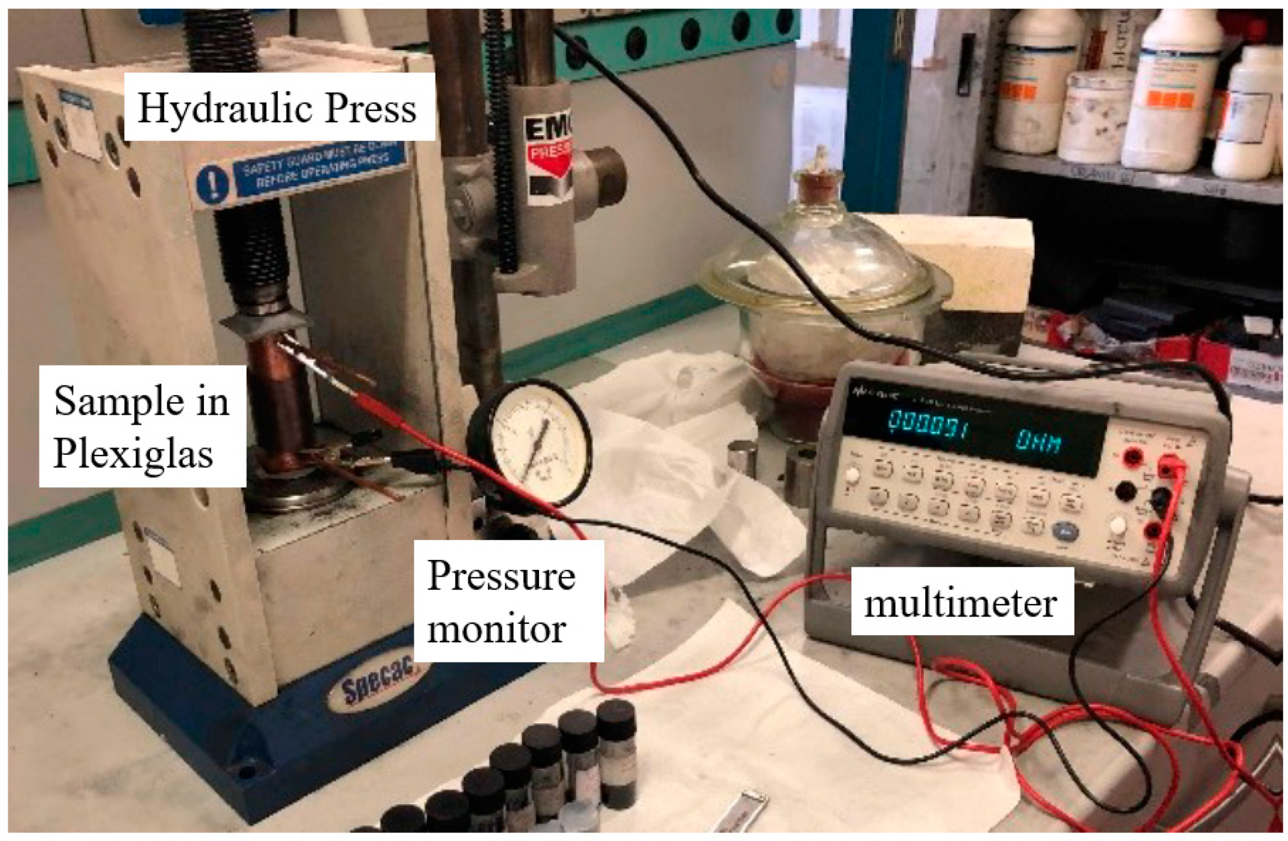
3.2. Conductivity Measurements

Thermal annealed sludge biochar was analyzed for electrical conductivity (DC mode) and compared with carbon black. The results are shown in Figure 8.
The value of conductivity obtained in the case of carbon black shows a gradual increase with increasing pressure. The values of conductivity for low pressure values in Figure 8 are comparable to the ones reported previously [34]. Pressure values similar to the values used in this study were adopted in [26]. The values of conductivity obtained in [26] were higher because of a higher temperature (>2000 °C) treatment on the carbon black.
Thermally annealed sludge biochar reaches an electrical conductivity value of around 300 S/m, and remains quite constant after a pressure of 200 bar. This was likely due to the higher graphitization degree reached at high temperatures [41,42]. Non-thermally annealed sludge biochar did not show any appreciable electrical conductivity, and was therefore not analyzed with this system.
Table 2 summarizes the electrical conductivity values obtained for biochar coming from various sources and treated at different temperatures. Irrespective of the origin of the biochar, the conductivity value increases with the treatment temperature.

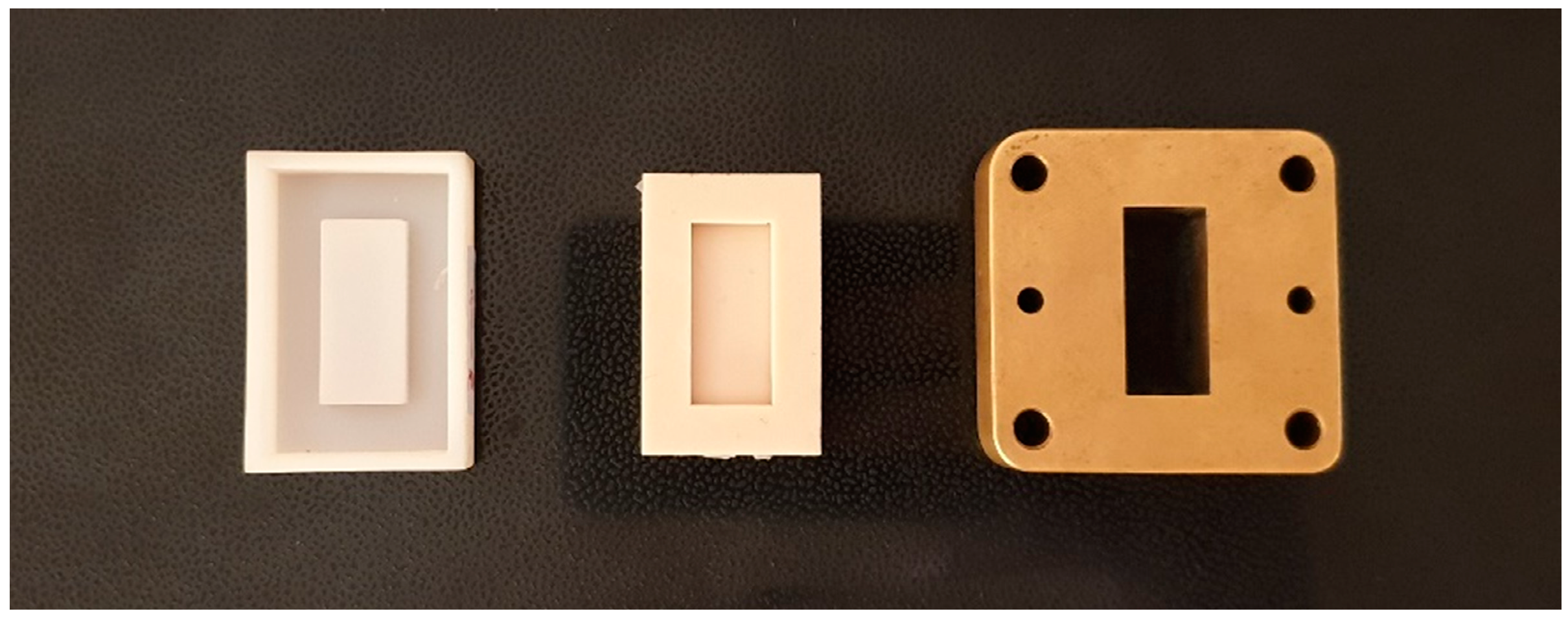
3.3. Shielding Effectiveness Evaluation

The transmission loss of the empty waveguide, the pristine resin and samples with 10 wt.% and 20 wt.% of sludge biochar are shown in Figure 9 (left panel). It can be seen that the addition of biochar reduces the value of transmission. The shielding effectiveness values for the biochar composites are shown in Figure 9 (right panel). For a composite sample with 10 wt.% biochar, the SE is almost 5 dB, which increases to 10 dB for a sample with 20 wt.% biochar. In order to achieve a further increase in SE, the biochar weight percentage can be increased. The thickness of the sample in this case is 4 mm; an increase of thickness can result in a further increase of the SE.
As reported in Section 2.2, the shielding effectiveness can be split between the reflective and dissipative losses. In Figure 10, the reflective loss, dissipative loss and the total shielding effectiveness for the composites with 10 wt.% and 20 wt.% are reported. It can be seen that the dissipative losses increase with the increase in the filler weight percentage.

4. Conclusions

In this article, we observed that biochar derived from sewage sludge can be a good contender as a filler in composites by performing electrical and morphological characterization. The conductivity of sewage sludge derived biochar was successfully increased by thermal annealing. Measurements of shielding effectiveness in the microwave frequency band required the use of a rectangular waveguide and samples of specific dimensions to fill the interior of the waveguide. Reusable silicone-based molds were made from a 3D-printed master mold. This facilitated the extraction of composites once they were polymerized. The addition of thermal annealed biochar, with superior conductive properties, showed an increase of the shielding effectiveness. The maximum value of shielding effectiveness was 10 dB with the addition of 20 wt.% of biochar. This value could be further increased by increasing the filler percentage or sample thickness.

Author Contributions

All authors have read and agree to the published version of the manuscript. P.S., and M.Y. made the composites, the waveguide measurements and discussion of the shielding effectiveness; M.B. and M.G. did the thermal annealing of the material and the DC conductivity analysis, M.L. provided the sludge biochar and provided useful insights on applications; all the authors contributed in writing the paper.

Funding

This research received no external funding.

Acknowledgments

Authors wish to acknowledge Salvatore Guastella for FESEM and EDX characterization and Massimo Rovere for Raman analysis.

Conflicts of Interest

The authors declare no conflict of interest.

References

  1. Lofrano, G.; Brown, J. Wastewater management through the ages: A history of mankind. Sci. Total Environ. 2010, 408, 5254–5264. [Google Scholar] [CrossRef] [PubMed]
  2. Cheremisinoff, P.N. Sludge: Management and Disposal; PTR Prentice Hall: Englewood Cliffs, NJ, USA, 1994. [Google Scholar]
  3. Spinosa, L. Evolution of sewage sludge regulations in Europe. Water Sci. Technol. 2001, 44, 1–8. [Google Scholar] [CrossRef] [PubMed]
  4. Sommers, L. Chemical composition of sewage sludges and analysis of their potential use as fertilizers 1. J. Environ. Qual. 1977, 6, 225–232. [Google Scholar] [CrossRef]
  5. Stabnikova, O.; Goh, W.-K.; Ding, H.-B.; Tay, J.-H.; Wang, J.-Y. The use of sewage sludge and horticultural waste to develop artificial soil for plant cultivation in Singapore. Bioresour. Technol. 2005, 96, 1073–1080. [Google Scholar] [CrossRef]
  6. Maksimova, S.; Kosaurova, D.; Pesheva, A. Recycling of wastewater treatment plants sludge in urban landscaping in West Siberia. Procedia Eng. 2015, 117, 232–238. [Google Scholar] [CrossRef] [Green Version]
  7. Wu, D.; Chu, S.; Lai, C.; Mo, Q.; Jacobs, D.F.; Chen, X.; Zeng, S. Application rate and plant species affect the ecological safety of sewage sludge as a landscape soil amendment. Urban. For. Urban. Green. 2017, 27, 138–147. [Google Scholar] [CrossRef]
  8. Singh, R.; Agrawal, M. Potential benefits and risks of land application of sewage sludge. Waste Manag. 2008, 28, 347–358. [Google Scholar] [CrossRef]
  9. Lindahl, G.M. Stable Solutions of Basic Aluminium Sulphate Containing Polynucleate Aluminium Hydroxide Sulphate Complexes. US Patent 4,536,384, 20 August 1985. [Google Scholar]
  10. Liang, J.; Zhang, S.; Huang, J.; Huang, S.; Zheng, L.; Sun, S.; Zhong, Z.; Zhang, X.; Yu, X. Comprehensive insights into the inorganic coagulants on sludge dewatering: Comparing aluminium and iron salts. J. Chem. Technol. Biotechnol. 2019, 94, 1534–1550. [Google Scholar] [CrossRef]
  11. Basri, M.H.; Don, N.M.; Kasmuri, N.; Hamzah, N.; Alias, S.; Azizan, F. Aluminium recovery from water treatment sludge under different dosage of sulphuric acid. In Proceedings of the Journal of Physics: Conference Series, Moscow, Russia, 13–15 November 2019; p. 012005. [Google Scholar]
  12. Korving, L.; Van Loosdrecht, M.; Wilfert, P. Effect of iron on phosphate recovery from sewage sludge. In Phosphorus Recovery and Recycling; Springer: Berlin, Germany, 2019; pp. 303–326. [Google Scholar]
  13. Bartoli, M.; Zhu, C.; Chae, M.; Bressler, D. Value-added products from urea glycerolysis using a heterogeneous biosolids-based catalyst. Catalysts 2018, 8, 373. [Google Scholar] [CrossRef] [Green Version]
  14. Bartoli, M.; Zhu, C.; Chae, M.; Bressler, D. Glycerol Acetylation Mediated by Thermally Hydrolysed Biosolids-Based Material. Catalysts 2020, 10, 14. [Google Scholar] [CrossRef] [Green Version]
  15. Tu, Y.; Tian, S.; Kong, L.; Xiong, Y. Co-catalytic effect of sewage sludge-derived char as the support of Fenton-like catalyst. Chem. Eng. J. 2012, 185, 44–51. [Google Scholar] [CrossRef]
  16. Wang, Y.; Zhang, Y.; Pei, L.; Ying, D.; Xu, X.; Zhao, L.; Jia, J.; Cao, X. Converting Ni-loaded biochars into supercapacitors: Implication on adsorption and dechlorination of pentachlorophenol from effluent by Ni–ZVI magnetic biochar composites synthesized from paper mill sludge. Chem. Eng. J. 2015, 271, 195–203. [Google Scholar]
  17. Devi, P.; Saroha, A.K. Simultaneous adsorption and dechlorination of pentachlorophenol from effluent by Ni–ZVI magnetic biochar composites synthesized from paper mill sludge. Chem. Eng. J. 2015, 271, 195–203. [Google Scholar] [CrossRef]
  18. Giorcelli, M.; Savi, P.; Yasir, M.; Miscuglio, M.; Yahya, M.H.; Tagliaferro, A. Investigation of epoxy resin/multiwalled carbon nanotube nanocomposites behavior at low frequency. J. Mater. Res. 2014, 30, 101–107. [Google Scholar] [CrossRef]
  19. Giorcelli, M.; Savi, P.; Miscuglio, M.; Yahya, M.H.; Tagliaferro, A. Analysis of MWCNT/epoxy composites at microwave frequency: Reproducibility investigation. Nanoscale Res. Lett. 2014, 9, 1–5. [Google Scholar] [CrossRef] [Green Version]
  20. Savi, P.; Yasir, M.; Giorcelli, M.; Tagliaferro, A. The effect of carbon nanotubes concentration on complex permittivity of nanocomposites. Prog. Electromagn. Res. M 2017, 55, 203–209. [Google Scholar] [CrossRef] [Green Version]
  21. Das, O.; Sarmah, A.K.; Bhattacharyya, D. Biocomposites from waste derived biochars: Mechanical, thermal, chemical, and morphological properties. Waste Manag. 2016, 49, 560–570. [Google Scholar] [CrossRef]
  22. Giorcelli, M.; Savi, P.; Khan, A.; Tagliaferro, A. Analysis of biochar with different pyrolysis temperatures used as filler in epoxy resin composites. Biomass Bioenergy 2019, 122, 466–471. [Google Scholar] [CrossRef]
  23. Giorcelli, M.; Bartoli, M. Development of coffee biochar filler for the production of electrical conductive reinforced plastic. Polymers 2019, 11, 1916. [Google Scholar] [CrossRef] [Green Version]
  24. Khan, A.; Savi, P.; Quaranta, S.; Rovere, M.; Giorcelli, M.; Tagliaferro, A.; Rosso, C.; Jia, C.Q. Low-Cost Carbon Fillers to Improve Mechanical Properties and Conductivity of Epoxy Composites. Polymers 2017, 9, 642. [Google Scholar] [CrossRef] [Green Version]
  25. Gabhi, R.S.; Kirk, D.W.; Jia, C.Q. Preliminary investigation of electrical conductivity of monolithic biochar. Carbon 2017, 116, 435–442. [Google Scholar] [CrossRef]
  26. Noda, T.; Kato, H.; Takasu, T.; Okura, A.; Inagaki, M. The electrical resistivity of carbon black under compression. Bull. Chem. Soc. Jpn. 1966, 39, 829–833. [Google Scholar] [CrossRef] [Green Version]
  27. Euler, K.J.; Kirchhof, R.; Metzendorf, H. The electric conductivity and related phenomena of compressed powder materials. Mater. Chem. 1979, 4, 611–629. [Google Scholar] [CrossRef]
  28. Espinola, A.; Mourente, M.; Salles, M.; Pinto, A. Electrical properties of carbons—resistance of powder materials. Carbon 1986, 24, 337–341. [Google Scholar] [CrossRef]
  29. Kendall, K. Solid surface energy measured electrically. J. Phys. D: Appl. Phys. 1990, 23, 1329–1331. [Google Scholar] [CrossRef]
  30. Celzard, A.; Marêche, J.F.; Payot, F.; Furdin, G. Electrical conductivity of carbonaceous powders. Carbon 2002, 40, 2801–2815. [Google Scholar] [CrossRef]
  31. Shui, X.; Chung, D.D.L. Submicron diameter nickel filaments and their polymermatrix composites. J. Mater. Sci. 2000, 35, 1773–1785. [Google Scholar] [CrossRef]
  32. Shui, X.; Chung, D.D.L. Electrical resistivity of submicron-diameter carbon-filament compacts. Carbon 2001, 39, 1717–1722. [Google Scholar] [CrossRef] [Green Version]
  33. Marinho, B.; Ghislandi, M.; Tkalya, E.; Koning, C.E.; de With, G. Electrical conductivity of compacts of graphene, multi-wall carbon nanotubes, carbonblack, and graphite powder. Powder Technol. 2012, 221, 351–358. [Google Scholar] [CrossRef]
  34. Sanchez-Gonzalez, J.; Macıas-Garcı, A.; Alexandre-Franco, M.F.; Gomez-Serrano, V. Electrical conductivity of carbon blacks under compression. Carbon 2005, 43, 741–747. [Google Scholar] [CrossRef]
  35. Giorcelli, M.; Savi, P.; Delogu, A.; Miscuglio, M.; Yahya, Y.H.; Tagliaferro, A. Microwave Absorption Properties in Epoxy Resin Multi Walled Carbon Nanotubes Composites. In Proceedings of the International Conference on Electromagnetics in Advanced Applications (ICEAA13), Torino, Italy, 9–13 September 2013. [Google Scholar]
  36. Savi, P.; Cirielli, D.; di Summa, D.; Ruscica, G.; Sora, I.N. Analysis of shielding effectiveness of cement composites filled with pyrolyzed biochar. In Proceedings of the 2019 IEEE 5th International forum on Research and Technology for Society and Industry (RTSI), Florence, Italy, 9–12 September 2019; pp. 1–4. [Google Scholar]
  37. Savi, P.; Yasir, M. Waveguide measurements of biochar derived from sewage sludge. IET Electron. Lett. 2020. (in print). [Google Scholar] [CrossRef]
  38. Weber, K.; Quicker, P. Properties of biochar. Fuel 2018, 217, 240–261. [Google Scholar] [CrossRef]
  39. Udayanga, W.C.; Veksha, A.; Giannis, A.; Lisak, G.; Lim, T.-T. Effects of sewage sludge organic and inorganic constituents on the properties of pyrolysis products. Energy Convers. Manag. 2019, 196, 1410–1419. [Google Scholar] [CrossRef]
  40. Keller, R.A. Gas—liquid chromatography of volatile metal halides. J. Chromatogr. A 1961, 5, 225–235. [Google Scholar] [CrossRef]
  41. Ngan, A.; Jia, C.Q.; Tong, S.-T. Production, Characterization and Alternative Applications of Biochar. In Production of Materials from Sustainable Biomass Resources; Springer: Berlin, Germany, 2019; pp. 117–151. [Google Scholar]
  42. Bartoli, M.; Nasir, M.A.; Jagdale, P.; Passaglia, E.; Spiniello, R.; Rosso, C.; Giorcelli, M.; Rovere, M.; Tagliaferro, A. Influence of pyrolytic thermal history on olive pruning biochar and related epoxy composites mechanical properties. J. Compos. Mater. 2019, 11. [Google Scholar] [CrossRef]
Figure 1. Measurement setup for the conductivity study of carbon fillers.
Applsci 10 01334 g001
Figure 2. Master mold, silicone mold and spacer with sample.
Applsci 10 01334 g002
Figure 3. Rectangular waveguide connected to a Vector Network Analyzer (VNA).
Applsci 10 01334 g003
Figure 4. Raman spectra of thermally treated and non-thermally treated biochar.
Applsci 10 01334 g004
Figure 5. FESEM captures of (a,b) non-thermal annealed and (c,d) thermal annealed sludge derived biochar at different magnifications.
Applsci 10 01334 g005
Figure 6. Energy Dispersive X-ray (EDX) analysis of (a) non-thermal annealed and (b) thermal annealed sludge derived biochar at different magnifications.
Applsci 10 01334 g006
Figure 7. FESEM on composites with 10 wt.% (left) and 20 wt.% (right).
Applsci 10 01334 g007
Figure 8. Conductivity measurement (DC) of thermal annealed sludge biochar and carbon black (*Vulcan® XC72R) as a function of applied pressure (0–1000 bar).
Applsci 10 01334 g008
Figure 9. Transmission loss versus frequency of composites with thermal annealed sludge biochar (left). Shielding effectiveness of biochar composites (right).
Applsci 10 01334 g009
Figure 10. Total shielding effectiveness and dissipation loss.
Applsci 10 01334 g010
Table 1. Elemental composition of carbonized sludge and annealed sludge.
ElementComposition [wt%]
Non-Thermal Annealed SludgeThermal Annealed Sludge
C55.2039.70
O39.7028.67
F2.07Not detected
Mg0.321.39
Al0.523.44
Si0.625.54
P0.644.17
S0.382.18
Cl0.570.29
KNot detected0.40
CaTraces6.57
TiNot detected0.60
FeNot detected5.75
ZnNot detected1.29
Table 2. Comparison between conductivity of different biochar produced in a wide temperature range compared with commercial carbon black.
Feedstock Used to Produce Biochar Pyrolysis Temperature [°C] DC Electrical Conductivity @ 1500 Bar (Order of Magnitude) [S/m] Reference
Miscanthus6500.3[22]
7002.2
7504
Coffee6000[23]
8000
1000300
Carbon blackCommercial product 1700[23]
Sewage sludge1000360This work

