A Method for the Installation Measurement and Alignment of a Mirror Unit in the Solar Dish Concentrator


1
College of Mechanical and Electrical Engineering, Hunan University of Science and Technology, Xiangtan 411201, China
2
Institute of Intelligent equipment Technology, Hunan Vocational College of Science and Technology, Changsha, Hunan 410004, China
*
Author to whom correspondence should be addressed.
Appl. Sci. 2020, 10(4), 1511; https://0-doi-org.brum.beds.ac.uk/10.3390/app10041511
Submission received: 13 January 2020
/
Revised: 19 February 2020
/
Accepted: 20 February 2020
/
Published: 23 February 2020
(This article belongs to the Collection Optical Design and Engineering)
Abstract
:The mirror unit installation error of the solar parabolic dish concentrator can adversely affect its optical performance causing optical intercept losses and hot spots on the absorber surface, which in turn affect safety. Thus, minimizing mirror installation error is considered very important. In this paper, a new method for the facet installation measurement and facet alignment of the mirror unit in the dish concentrator is presented. Firstly, a “clean” facet installation error measurement method using photogrammetry is presented. The photogrammetry measures the spatial coordinates of three feature points to reverse the mirror facet alignment error parameters. Next, two novel methods, a three-rotation alignment method and two-rotation alignment method for aligning the mirror facet are presented and corresponding mathematical models. The advantage of these alignment methods is that the adjustment value and order for each support bolt can be determined before the mirror facet is aligned, which could provide quantitative adjustment information to operator and avoid repeated adjustments. Finally, validity of the installation measurement and facet alignment method was verified by a numerical simulation and an experiment using a metal facet alignment. The presented methods do not rely on the geometry of the reflector mirror and could therefore have extensive uses in applications such solar tower and trough concentrator.
1. Introduction
Solar energy is a clean and environmental friendly renewable energy source, which is plentiful and can be widely distributed. Developing and utilizing solar energy is an important way to solve energy shortages and environmental pollution problems [1,2,3]. The dish-Stirling concentrated solar power system (DS-CSP system) focuses sunlight onto a metallic coil surface in a heat absorber via a parabolic dish concentrator and heats a working medium (usually hydrogen or helium gas) in a metal coil, which then drives a Stirling engine in order to generate electricity [2,3]. The DS-CSP system has the advantages of a high solar-to-electricity conversion efficiency (the record is 31.25%), flexible arrangement, and high modularity, and is thus considered a high-grade solar thermal utilization system with wide application prospects in the future [3,4,5].
In practice, large dish concentrators are usually assembled with many mirror units forming the parabolic reflecting mirrors and each mirror unit must be accurately fixed in a preset position within the truss structure [6,7,8,9,10]. The fixation or facet adjustment is realized by three support-adjustment structures located on the posterior side of the mirror unit (Figure 1c). If facet alignment error exists after the mirror unit is installed, the shape accuracy of the parabolic concentrator surface can be affected. This may lead to problems such as a non-uniform flux distribution on the metal coil surface, which can cause unsteady motion of the multi-cylinder engine [11,12]. This could also lead to the focal spot being moved outside the absorber, which can cause optical intercept losses as well as the formation of “hot spots” on the metal coil surface leading to erosion or damage of the metal tube. As such, these problems can directly affect the economics and safety performance of the DS-CSP system during operation. Correctly aligning the mirror units in the dish concentrator while minimizing installment error is therefore of great importance to overall performance [6]. The development of an effective mirror alignment method or alignment tool to guide mirror facet alignment during operation would be extremely valuable.
The current methods of the mirror facet alignment and mirror slope error measurement in the solar concentrator field mainly include laser-scanning, reflection imaging, and photogrammetry methods [13,14,15]. Laser scanning is derived from a ray tracking method based on the mirror reflection law. A set of reflection mirror detection devices based on Video Scanning Hartmann Optical Test (VSHOT) were previously developed to test the mirror slope error of a dish concentrator [16,17]. The VSHOT is a laser device used to measure the slope of the reflector directly at many positions on the concentrator mirror surface. Maccari and Montecchi [18] developed a set of optical profilometers based on a He–Ne laser device for measuring the slope error of a trough concentrator. While effective measurements have been made using the scanning process, the method is very time-consuming and difficult to implement in “real-time”, unable to real-time instruct the mirror facet alignment.
Using the reflection imaging method, Diver et al. [19] developed a mirror alignment tool with an artificial light source to guide the mirror facet alignment in a multi-dish concentrator (CPG-460). Alignment was accomplished by adjusting the facet aim such that the reflected image falls on a predetermined location. Steffen et al. [20] and Andraka et al. [21] suggested using a color 2f alignment method for measuring the mirror shape error of a dish concentrator by utilizing a video camera and a color target affixed to a lightweight tower at a distance nearly twice the focal length (2f) from the vertex of the dish concentrator. The camera and target were centered on the optical axis of the concentrator. Ulmer et al. [22] developed color-coded targets for measuring the slope error of a parabolic dish concentrator. The method used a flat target with colored stripes placed close to the focal plane of the concentrator and a digital camera located at an observation point on the optical axis at some arbitrary distance. Andraka et al. [11] proposed a method to implement certain alignments in manufacturing processes using the Fringe Analysis Slope technique, which was shown to reduce the time taken to align the mirror of each dish concentrator to approximately 2 h. Using the reflection imaging method, the target image could be displayed in “real-time” on the mirror surface of the concentrator so as to guide the mirror installation alignment however pre-calibration was required to set the spatial relationships between the devices, which reduce the flexibility and convenience of this method. Such as the color 2f alignment [20,21] and color-coded target methods [22] both required alignment of the center-line of the camera and target with the focal axis of the dish concentrator. Furthermore, it was found that the adjustment value and adjustment order of each support bolt could not be determined when the mirror facet was aligned hence leading to the requirement for repeat adjustments of the support bolts.
Shortis and Johnston [23,24] adopted a photogrammetry method to measure the shape error of the SG3 400 m2 solar dish concentrator. Similarly, Burgess et al. [25] used photogrammetry in the construction of a 500 m2 dish concentrator to control the assembly of a convex paraboloidal jig for ensuring the installation accuracy of each mirror unit. Blázquez et al. [26] measured the surface shape error of the dish concentrator with photogrammetry at different elevation angles. Finally, Xiao et al. [8] measured the spatial coordinates of ten randomly distributed positioning targets on each mirror unit in a dish concentrator. Again, the adjustment value and adjustment order of each support bolt could not be determined when the mirror facet was aligned. The photogrammetry method is flexible, simple and convenient and theoretically, could be used to measure the surface shape error of any geometrical concentrator in order to guide the mirror facet alignment for the dish concentrator and trough concentrator [27,28,29,30]. However, a large number of markers on the reflective mirror of the concentrator are needed, and could cause the reflective mirror become optically polluted, therefore, a “clean” mirror facet installation measurement method should be developed.
In the above literature, whilst measuring the surface error of the concentrator to guide the mirror installation or facet alignment, the adjustment value and order of each support bolt could not be determined before the alignment of the mirror facet. In this paper, we focus on the facet installation error measurement and facet alignment of the mirror unit (the surface quality of the mirror unit installed is considered to be satisfactory). A “clean” mirror facet installation measurement method is presented. The spatial coordinates of three feature points were measured by photogrammetry to reverse the facet alignment parameters of the mirror unit (i.e., the axis vector and vertex position vector of the mirror unit). The feature points were pasted on the reflective mirror and formed a triangular distribution (in Section 3). Next, based on the results of the mirror facet installation measurements, a three-rotation alignment method (adjusting three support bolts in turn) and two-rotation alignment method (adjusting two of the three support bolts) was investigated and a corresponding mathematical model was established (in Section 4 and Section 5). The advantage of the two presented mirror facet alignment method is that the adjustment value and adjustment order of each support bolt can be determined prior to the alignment of the mirror facet, which can therefore provide quantitative adjustment information to the operator. The methods were verified by a numerical simulation and an experimentally using a metal facet alignment. The errors and ways to improve the methods in relation to the accuracy of the mirror facet alignment are discussed (in Section 6). Finally, future work aimed at using the real-time monitoring and alignment system is briefly discussed (in Section 7).
2. Support-Adjust Structure of Mirror Unit
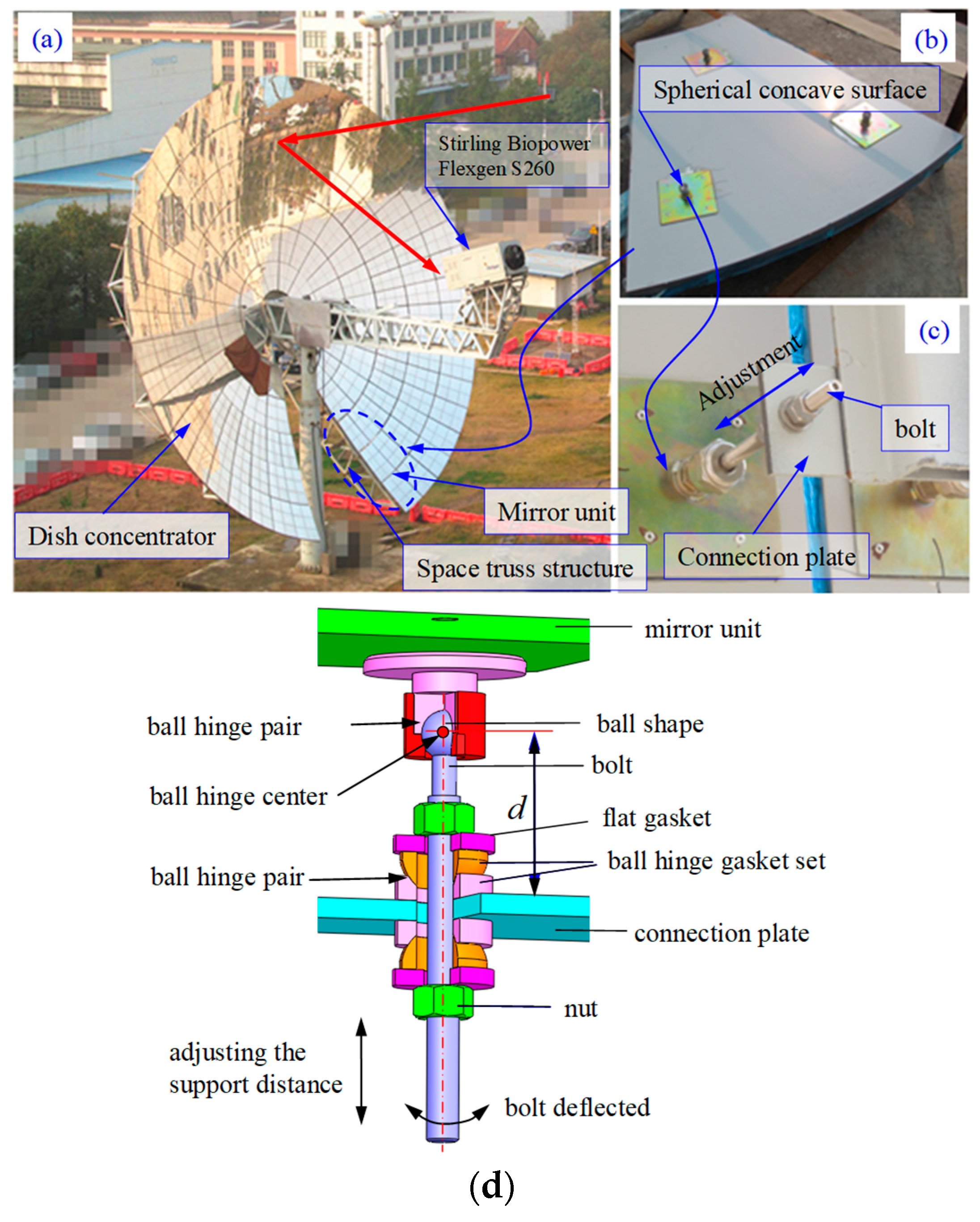
A 38 kW dish-Stirling solar power system (XEM-Dish System [4,5]) was designed and built by our team and Xiangtan Electric Manufacturing Group (in China) and is shown in Figure 1a. The dish concentrator (diameter 17.70 m and focal length 9.49 m) was made up of 164 mirror units in the XEM-Dish System. Each mirror unit was fixed onto the connection plate of the space truss structure using three or four bolts and the bolts were adjusted to align the mirror (Figure 1c). An image of the system and the assembly model of the support-adjust structures at the back of the mirror units are shown in Figure 1c,d, respectively. Each support-adjust structure consists of a bolt, ball-hinge gasket set (including a convex and concave spherical gasket, forming the ball hinge pair), and nut (Figure 1d). This is the conventional structure for supporting and adjusting the mirror unit in a dish concentrator and has been widely used [21]. As shown in Figure 1d, the upper end of each bolt had ball-shaped design paired with a spherical concave surface (Figure 1b) on the back of the mirror unit forming the ball-hinge pair. The center of the ball-hinge pair is referred to as the ball hinge center. The ball-hinge gasket set and nuts were installed on the upper and lower sides of the bolt and all the nuts were tightened to fix the bolt and ball hinge center. Once bolts 1, 2, and 3 were fixed, installation of the mirror unit was complete.
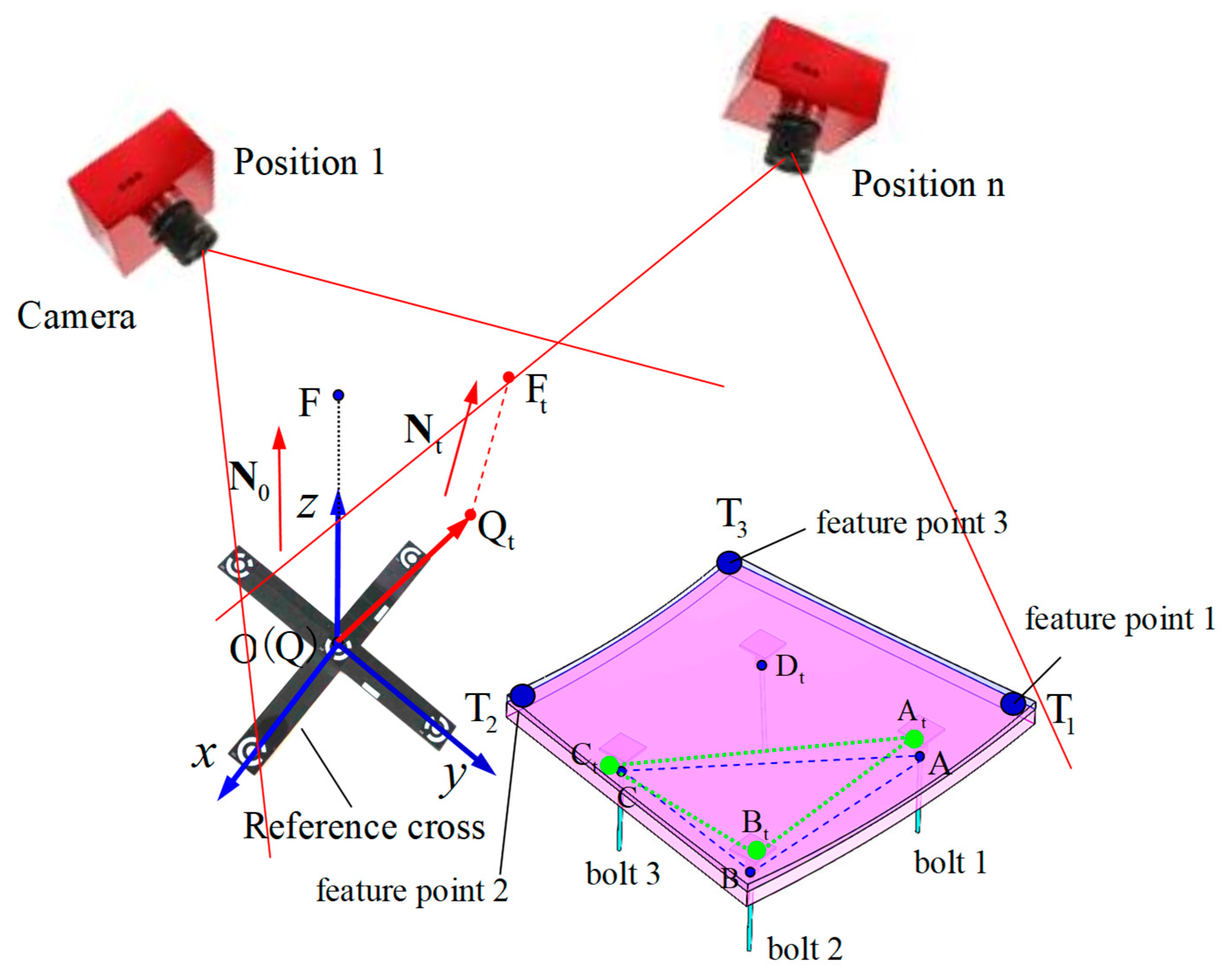
In the O-xyz coordinate system of the dish concentrator (Figure 2), the origin O is the vertex of the parabolic reflecting mirror and the z-axis points to the focal point F on the parabolic reflecting mirror. A (i.e., OA), B, and C are position vectors of the ball hinge center with coordinates (A, B, and C) on the back of the mirror unit corresponding to the ball hinge center of bolts 1, 2, and 3. The facet alignment parameter of the mirror unit was described by axis vector N0 and vertex position vector Q (vertex point Q). In ideal conditions, i.e., when the mirror unit has no installation error, and for a parabolic reflecting mirror surface, Q is coincident with the origin O, such that Q = [0, 0, 0] and N0 is coincident with the z-axis such that N0 = [0, 0, 1.0]. If the reflecting mirror surface is flat, Q is the centroid of the mirror’s plane and N0 is the normal vector, which will be used in Section 6.2. In general, facet alignment error that exists after initial installation of mirror unit is called facet 1 in this paper. In this condition, the axis vector of the mirror unit has changed from N0 to Nt, point Q has moved to point Qt (with position vector Qt), and the ball hinge center has moved to the point At~Ct, as shown in Figure 2.
The optical performance of a dish concentrator is adversely affected by installation error, which should thus be reduced or eliminated. As an example, the facet alignment process was carried out as follows. Bolt 1 was first adjusted by unscrewing the nuts on either sides of the bolt while bolt 2 and bolt 3 remained fixed and bolt 1 was then moved up or down a certain distance dA to make the mirror unit rotate around the axis BtCt changing the mirror facet alignment. Next, the nuts were tightened on both sides of bolt 1 and the steps were performed to adjust bolts 2 and 3 in turn to achieve facet alignment of the mirror unit. The mirror unit thus underwent three rotational motions with the axis of rotation consisting of two ball-hinge center points. In order to achieve efficient and accurate alignment, the facet alignment parameters was measured (vertex position vector Qt and axis vector Nt) and the adjustment values dA, dB, and dC of bolt 1, 2, and 3 were determined as well as the adjustment order, respectively. These aspects are the highlights of this study.
3. Measurement of the Mirror Facet Alignment
3.1. Measurement Method
In order to rapidly and cleanly measure the facet alignment of a mirror unit after installation, a method to reverse the mirror facet using the coordinates of three feature points was proposed. The steps for this method are as follows:
(1) Three circular marks are pasted on the reflective mirror of the mirror unit forming a triangular distribution with known positions. The center of each circular mark is used for the feature points denoted T1, T2, and T3 with position vectors T1 (T1 = OT1), T2, and T3, respectively (Figure 2). Under ideal condition, the coordinates of the feature points are known.
(2) After the initial installation of the mirror unit (i.e., facet 1), the points T1, T2, and T3have moved to positions T1t, T2t, and T3t, respectively. Using the photogrammetry method [29], the coordinates of point T1t, T2t, and T3t and their corresponding position vectors T1t, T2t, and T3t (Equation (1)) are determined.
(3) To calculate the facet parameters (Qt and Nt) and position vectors At, Bt, and Ct of the ball-hinge center, a one translational two rotational rigid body moving method (OneT-TwoR method) was developed (Figure 3). Where the measure coordinate system of photogrammetry overlaps with the design coordinate system O-xyz of the concentrator, the cruciform target or checkerboard target are used for calibration, which will be described in subsequent sections.
In Equation (1), where t1, t2, and t3 are the position error vectors of the feature points T1, T2, and T3 determined by photogrammetry respectively.
3.2. Mathematical Model of the Mirror Facet
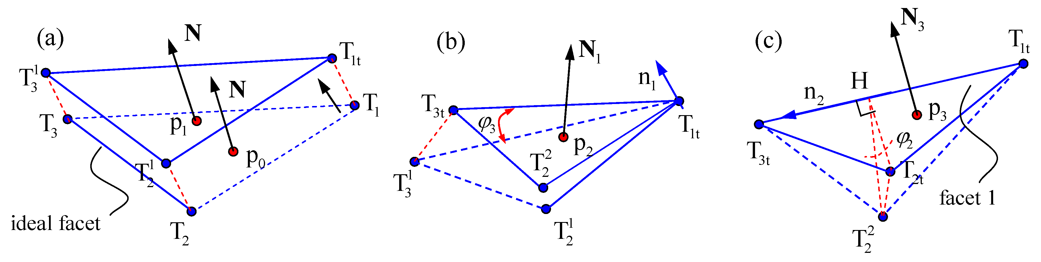
As previously stated, to calculate the facet parameters of the mirror unit, the OneT-TwoR method was developed (Figure 3). Briefly the method determines facet 1 based on the position of the mirror unit as it arrives at after one translational motion and two rotational motions. Therefore, the position vectors T1, T2, T3 and T1t, T2t, T3t before and after installation of the mirror unit respectively, which could be used to determine the motion parameters of the OneT-TwoR method. According to motion parameters of the OneT-TwoR method, we can then calculate Qt and Nt. The OneT-TwoR process of mirror unit and the deduction of mirror facet mathematical model could follow the Step 1, Step 2, and Step 3 in this section. In Figure 3a, the point p0 (position vector p0) and axis vector N are located in the ideal position to describe rigid body motion and derive the formulas.
To derive the formula, a function for determining vector rotating around the unit vector with degrees to get the vector can be defined by [31]:
where superscript T denotes the transpose.
Furthermore, by expanding and reducing the middle section of the Equation (2), the function can be given by:
Step 1: The translational motion of the mirror unit causes point T1 move to point T1t (Figure 3a) and at the same time, p0 moves to p1. The position vector p1 can then be given as:
Step 2: The mirror unit rotating about point T1t (unit vector of rotation axis is n1) causes point to rotate to point T3t. At this time, point p1 moves to p2 and N becomes N1. The rigid body motion satisfied the rules , where is magnitude of the vector A. According to the triangle cosine theorem, the rotation angle can be deduced as:
The unit vector is perpendicular to both vector and vector and can be calculated by:
According to the motion parameters (n1 and rotation angle ) of the mirror unit, p2 and N1 can be deduced as:
Step 3: The mirror unit rotating about the axis T1tT3t (unit vector of rotation axis ) causes point to rotate to position T2t (Figure 3c). At this time, point p2 moves to p3 and N1 becomes N3. The mirror unit thus has moved from the ideal facet to facet 1. In Figure 3c, the distance between axis T1tT3t and point is , which satisfies the . Again, according to the triangle cosine theorem, the rotation angle can be deduced as:
According to the motion parameters of mirror unit in step 3, the vectors p3 and N3 can be deduced as:
where , .
Putting Equation (4) and Equation (7) into Equation (9), the vector p3 can be rewritten as:
where N in Equation (9) and p0 in Equation (10) are both arbitrary. Putting the vertex position of vector Q and N0 to the Equation (9) and Equation (10) respectively, the vertex position vector Qt and axis vector Nt can be determined as:
Similarly, by replacing p0 in Equation (10) with vector A, B and C, the position vector At, Bt and Ct can be determined as:
Thus, a mathematical model relating the facet alignment of the mirror unit to the coordinates of the feature points has been established. Moreover, the relationship between the facet alignment and coordinates of the ball-hinge center has been determined through the Equations (11) and (12), which provides the foundation for quantitative alignment of the mirror facet.
4. Equivalent of the Facet 1
The movement process of a rigid body is reversible, i.e., a rigid body that can move from facet 1 to facet 2 can also take the reverse path from facet 2 to 1. In this paper, the facet alignment process of a mirror unit is taken as a three-rotation movement and the axis of rotation consists of two ball-hinge center points (Section 2). The OneT-TwoR rotational movement does not correspond to the alignment process of the mirror facet, as in Section 3.2, because n1 may not consist of two ball-hinge center points, as shown in step 2. Thus, a three rotation one translational rigid body movement (ThreeR-OneT) to get to facet 1 (Figure 4) was developed according to the facet alignment process of a mirror unit with three-rotational movement. This means facet 1 of the mirror unit arrives at this position from the ideal position through three rotational motions and one translational motion (Figure 4). As such, the facet alignment error can be reduced or eliminated by reversing the order of motion.
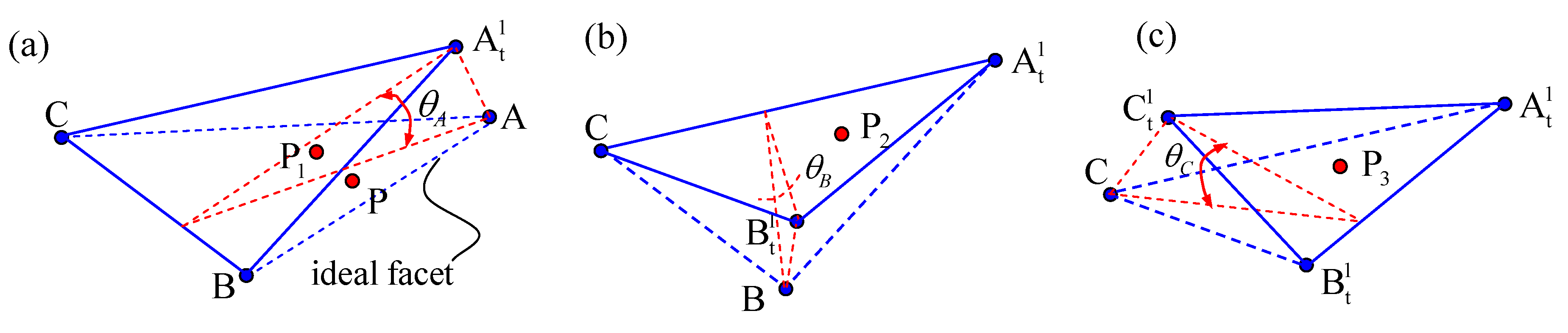
Theoretically, three rotational motions of mirror unit can occur in six different orders: ABC (rotate point A, B, and C in turn, see Figure 4), ACB, BAC, BCA, CAB, or CBA. In this section, taking the order ABC as an example the mathematical model of the mirror facet after the ThreeR-OneT motion was established. The process for the ThreeR-OneT motion of the mirror unit is as follows:
- (1)
- The mirror unit located at the ideal facet, then rotate the mirror unit angle around the axis of CB (Figure 4a).
- (2)
- The mirror unit is rotated at angle around axis (Figure 4b).
- (3)
- The mirror unit is rotated at angle around axis (Figure 4c).
- (4)
- The mirror unit is translated by the vector M1 = [x, y, z].
Moreover, additional mathematical models of rotational order can be established by following the above steps.
According to the mathematical model derived in Section 3.2, the position vector of point P (Figure 4a) after each movement phase can be derived as:
where , , and are the unit vectors of the rotational axis and can be defined as: , , , , .
Replacing vector P in Equation (13) with the vertex position vector Q of the mirror unit gives the position vector after ThreeR-OneT motion and is defined by:
where , is the total rotation matrix of order ABC, which can be calculated by:
According to the total rotation matrix , the axis vector of mirror unit after ThreeR-OneT motion is given by:
In order to make mirror unit move to facet 1 after the ThreeR-OneT motion, the key is to find the rotation angles , , and that make vector parallel to vector , and then to determine M1 by .
5. Mirror Facet Alignment Method
The mirror installation error consists of the axis vector error and vertex position error. In this paper, only the alignment of the axis vector error of the mirror unit was investigated. There are three reasons for this: (1) the axis vector error of the mirror unit (similar to the concentrator tracking error) affects the optical performance of the dish concentrator and is much larger than the vertex position error; (2) the vertex position error can only be completely eliminated by the translational motion of the mirror unit however the mirror facet adjustment process is a series of rotational motions (Section 2) such that it is difficult to completely eliminate the vertex position error; and (3) the truss structure in the dish concentrator will only have a certain level of accuracy determined by the manufacturing process, which controls the vertex position error.
5.1. Three-Rotation Alignment Method
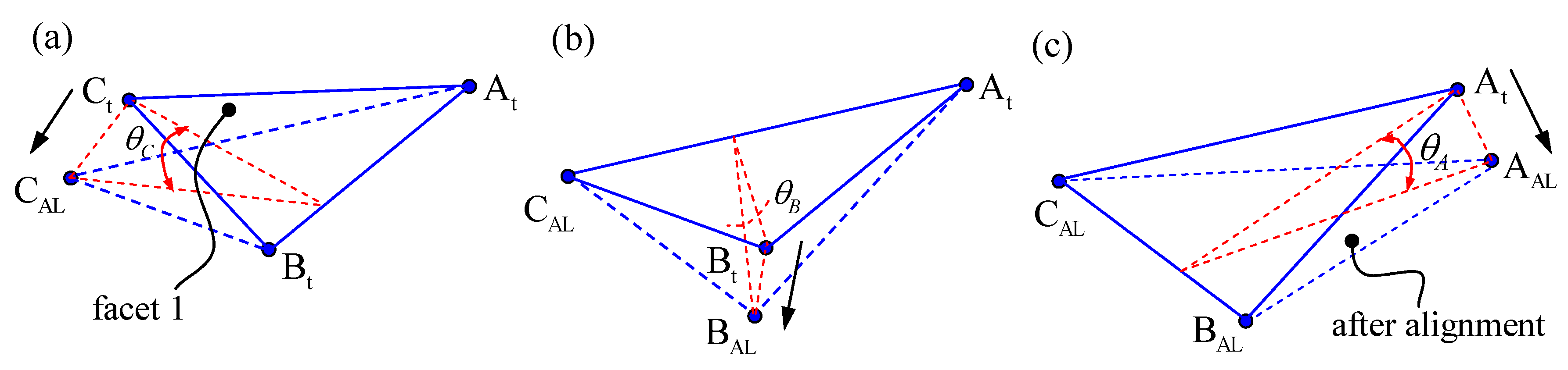
In this section, a method to determine the angles of rotation , , and is presented. When is parallel to the , the angles of rotation , , and can be calculated and facet alignment of the mirror unit can be achieved by rotation order CBA, such that the axis vector error is aligned. This is the three-rotation alignment method. The facet alignment process (Figure 5) includes the following steps:
- (1)
- The mirror unit starts at facet 1 after initial installation and by adjusting bolt 3 is rotated according to the mirror unit angle about axis and point Ct moves to point CAL.
- (2)
- Bolt 2 is adjusted in order to rotate the mirror unit at angle about axis and point Bt is moved to point BAL.
- (3)
- Bolt 1 is adjusted to rotate the mirror unit at angle about axis and point At moves to point AAL.
After three adjustments, the vector Nt becomes NAL, Qt becomes QAL and can be calculated by:
where ; ; ; ; ; .
The facet alignment error of the mirror unit can be described by error angle and distance L. The error angle is the angle between the actual axis vector and the ideal axis vector N0 and the error distance L is the distance between the actual and ideal vertex Q. After three rotations, and L can be calculated by:
According to matrix HABC, vector has strong nonlinearity, so that the parallel problem of vector and Nt is equivalent to the minimum optimization problem of their intersection angle. The optimization objective can be defined as:
which can be calculated by the Genetic Algorithm method.
More specifically, using the Genetic Algorithm Tool in Matlab (R2012a) [32], Equation (19) was optimized for determining the rotation angle , , and . To improve the optimization accuracy of the results, Equation (19) is optimized m times (m = 45 in this paper) to get m sets of angle , , and . Finally, a set of angles , , and is selected to make the error angle as small as possible for the particular facet alignment parameters of the mirror unit.
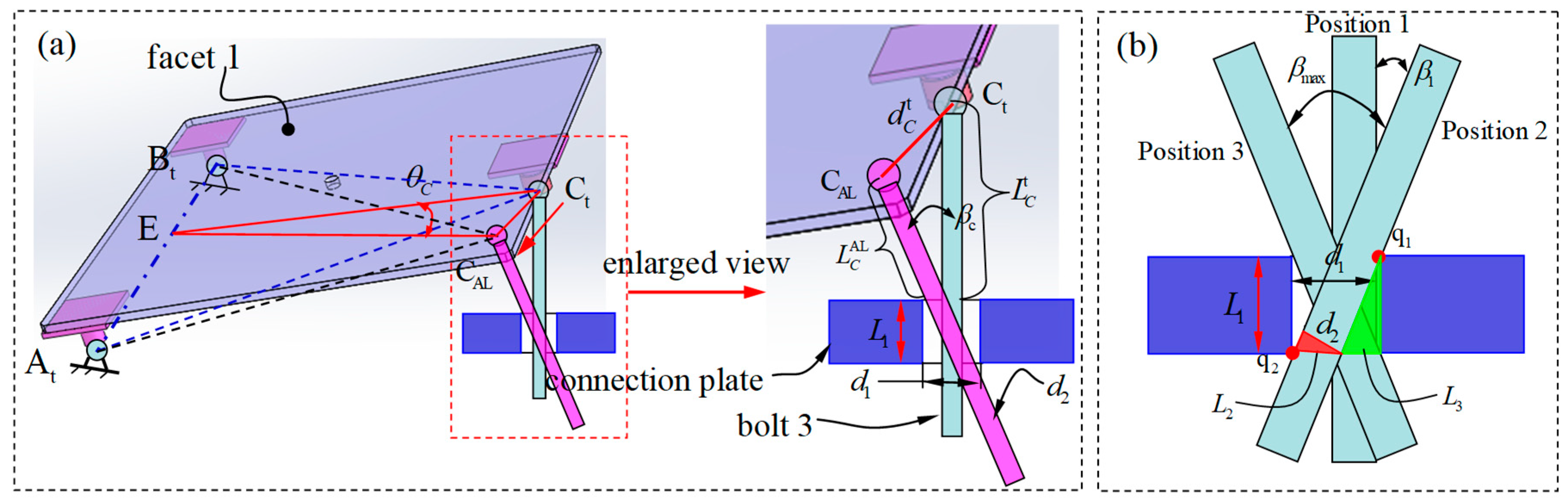
Under the actual operation, the facet alignment of the mirror unit is adjusted using bolts 3, 2, and 1, and it is necessary to turn the rotation angles , , and to the adjust values of bolt 3, 2, and 1, respectively. These adjustment values are determined in relation to the support-adjust structure. Taking the adjustment of bolt 3 as an example (Figure 6a), bolt 3 can be adjusted by rotating the mirror unit around axis with rotation angle is while bolts 1 and 2 remain unchanged. Bolt 3 will be deflected in the connection hole during the adjustment process as it is close to the triangle. The triangle geometry satisfies following relationship:
where, is the support length of bolt 3 before adjustment, is length of bolt 3 after adjustment, is distance moved by the ball-hinge center C, where , and is the intersection angle before and after adjusting bolt 3. , where is the maximum intersection angle before and after the adjustment of bolt 3 (Figure 6b) and can be calculated as Equation (22).
In Figure 6b, the relationship between the diameter d2of the bolt, thicknessL1 of connection plate, and diameter d1 of the connection hole can be described by:
where L2 is the hypotenuse length of the red triangle (left hand side), L3 is right-angle side length of the green triangle (right hand side). Hence, the angle can be derived as:
Normally, the diameter d2 of the bolt is smaller (2.0~4.0 mm) than the diameter d1 of the connection hole, so that will also be small. Due to and assuming , Equation (20) can be rewritten as . The adjustment value dC of bolt 3 is the difference between and therefore . Based on the same simplification, the adjustment values of dA, dB, and dC of bolt 1, 2, and 3, respectively, in the three-rotation alignment process can be given by:
where , , and are sign coefficients for determining the direction of adjustment of bolts 3, 2, and 1, respectively. If the sign coefficient is equal to 1, the bolt is adjusted downward whereas if the sign coefficient is equal to −1, the bolt is adjusted upward. Since , the bolt adjustment is downward (i.e., < ). Furthermore, according to the specific pitch of the bolt (threads/mm), the adjustment value of the bolt can be output as the rotational turns of the nut.
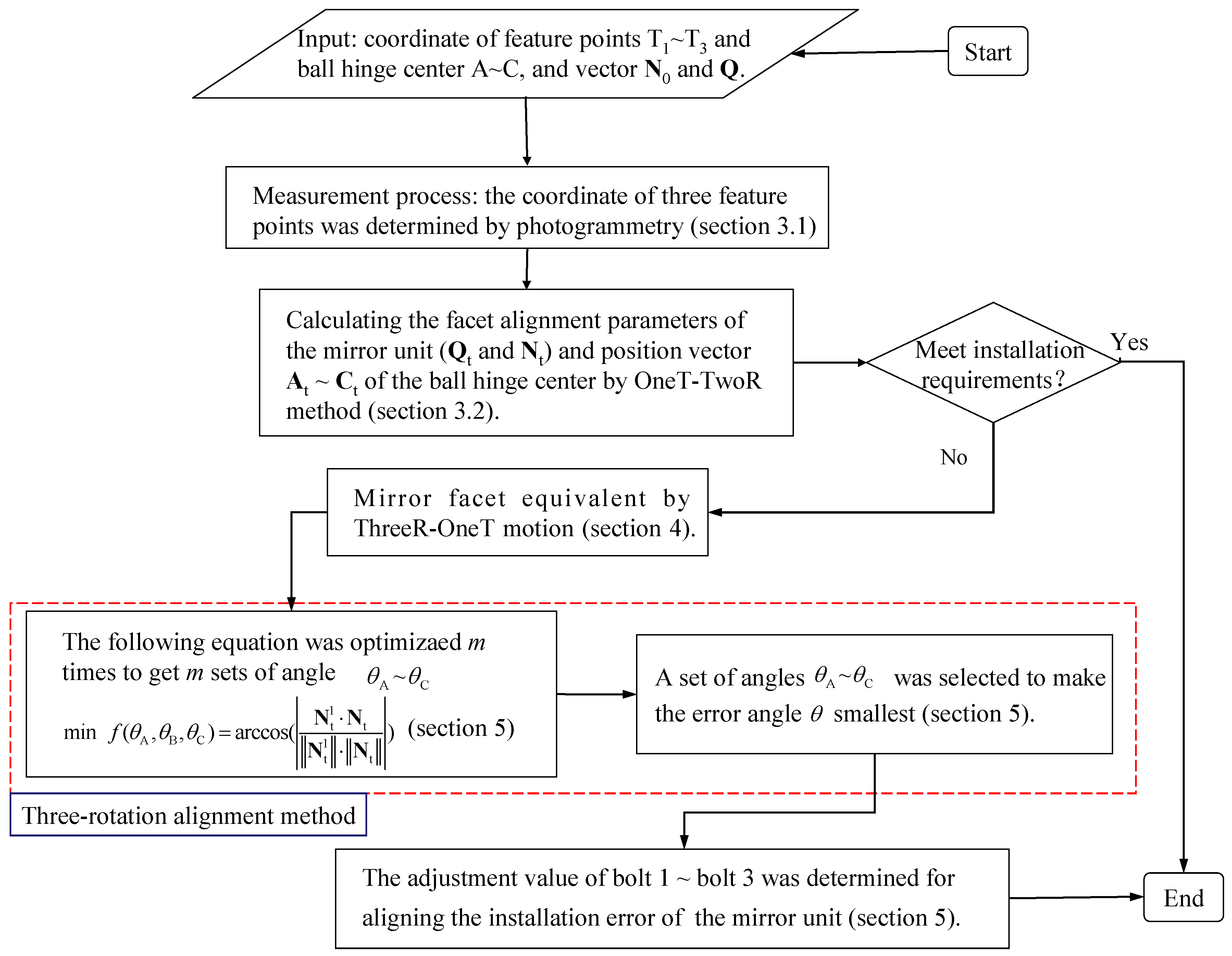
A flowchart of the three-rotation alignment method is shown in Figure 7. The inputs are the known parameters including the coordinates of feature points T1~T3, ball-hinge centers A~C, and ideal facet parameters of the mirror unit (N0 and Q). These parameters are taken from the technical drawing of the dish concentrator. In the measurements, the spatial coordinates of three feature points on the mirror unit can be determined by the photogrammetry method, which is the only measurement process in the three-rotation alignment method. Finally, the adjustment value of bolts 1, 2, and 3 can be determined by the mathematical model (Section 3.2) and three-rotation alignment model (Section 5.1). Theoretically, the requirement of only a single alignment of the mirror unit can eliminate the axis vector error and avoid repeated adjustments so that the process is simple and convenient. In addition, the spatial coordinates of three feature points can be measured in real-time by the two visual measurement methods [33,34] to realize real-time monitoring and guidance of the mirror facet alignment. This could be extremely helpful in improving the accuracy and efficiency of mirror installation.
5.2. Two-Rotation Alignment Method
The two-rotation alignment method only adjusts two bolts and the third is not adjusted (i.e., the adjustment value is 0 mm). This could improve the efficiency of mirror facet alignment. The mathematical model of the two-alignment method is presented in this section.
In many cases, the distance between any two ball-hinge centers in the mirror unit is much greater than the adjustment value of the bolts, so the rotation angles , , and are micro-amounts in ThreeR-OneT motion (Figure 4). For example, due to when mm and mm. When angle rad, the maximum relative error is less than 0.6% satisfied by ; therefore, it is assumed that , , and , as well as and . Based on these assumptions, abandoning the second order, and allowing the micro-amounts (such as the is second order microamount) to be negligible, the total rotation matrix (Equation (15)) can be simplified in order to derive the linearization of the total rotation matrix as:
where , , .
In the same way, the linearization of the total rotation matrix of different permutations (ACB, BAC, BCA, CAB, or CBA) could also be derived, and it was found that the linearization of each total rotation matrix are the same as such that . This shows that when the rotation angle ~ is small, the facet parameter of the mirror unit does not affect the rotation order in ThreeR-OneT motion. Therefore, the equivalent of facet 1 is always adopted as the ABC rotation order (Section 4). The mirror facet alignment adopts the CBA rotation order (Section 5) in this study.
Using matrix to replace , the axis vector can be deduced and is given by:
Then, according to the x-axis and y-axis component of the vector and vector are equal respectively for determining the relationship between the angles ~ as:
In Equation (26), there are three unknown variables (~) but only two equations, so the solution of Equation (26) is not unique. If only adjusting two bolts and the other bolt is not adjusted, Equation (26) will have only one solution. This is the mathematical basis of the two-rotation alignment method. The specific calculation process is that , , and are selected in turn and substituted into Equation (26) to calculate three set angles ~. Then, the set of angles ~ can be selected to make the error angle smallest (Equation (18)) for the facet alignment parameters of the mirror unit. Finally, the adjustment value dA~dC of the bolts 1~bolt 3 can be determined by the Equation (23). The two-rotation and three-rotation alignment methods (Section 5.1) have the same principle. The differences is only in solving the rotation angle ~ (the red dashed box in Figure 7) but the other steps are the same. It can be shown that the two-rotation alignment method is a special case of the three-rotation alignment method.
6. Experimental Verification of the Mirror Alignment Method
In this section, the theoretical validity of the three-rotation and two-rotation alignment methods was assessed by numerical experiment and the practice effectiveness of the mirror facet installation measurement and facet alignment methods was verified by a experimentally using a metal plane facet alignment. Finally, the errors and ways to improve the methods in relation to the accuracy of the mirror facet alignment are discussed.
6.1. Numerical Experiment
Theoretical validity of the three-rotation and two-rotation alignment method was assessed by numerical experiments. The detail and steps of this numerical experiment as follows:
(1) Ideal parameters of the mirror unit. The outermost ring mirror unit in the 38 kW XEM-Dish system (Figure 1) was selected as Part1 and then the support position of bolt 3 was changed as Part2 for the numerical simulation. Due to the numerical experiment did not involve measuring the coordinate of the feature points, so the ball-hinge centers A, B, and C were taken as feature point T1, T2, and T3, respectively. In ideal facet, the coordinates of the ball-hinge center and feature point, as well as the axis vector N0 and position vector Q of the vertex in Part 1 and 2 as shown in Table 1 (in coordinate system O-xyz).
(2) Installation error of the mirror unit. In the numerical experiments for Parts 1 and 2, the installation error of the mirror unit was introduced by ThreeR-OneT motion in order BCA and translation vector M1 = [15.0, 12.0, 5.0] (in Section 4). That is the Parts 1 and 2 through ThreeR-OneT motion from ideal facet to get error condition (i.e., facet 1). In the ThreeR-OneTwith order BCA, the error combination of rotation angles , and is given by:
where, is the maximum rotation angle; n is the equal divided number; i, j and k are all integers within the range of 1~nand the initial values of them are 1. In this paper, = 52.40 mrad and n = 4.
The combination process of the angles , , and is that if k from 1 to n cycle once, j = j + 1; if j from 1 to n cycle once, i = i + 1. The combination number was , . For example, if N = 21 presents i = 2, j = 2, and k = 1, i.e., = −8.73 mrad, = −8.73 mrad, and = −26.20 mrad.
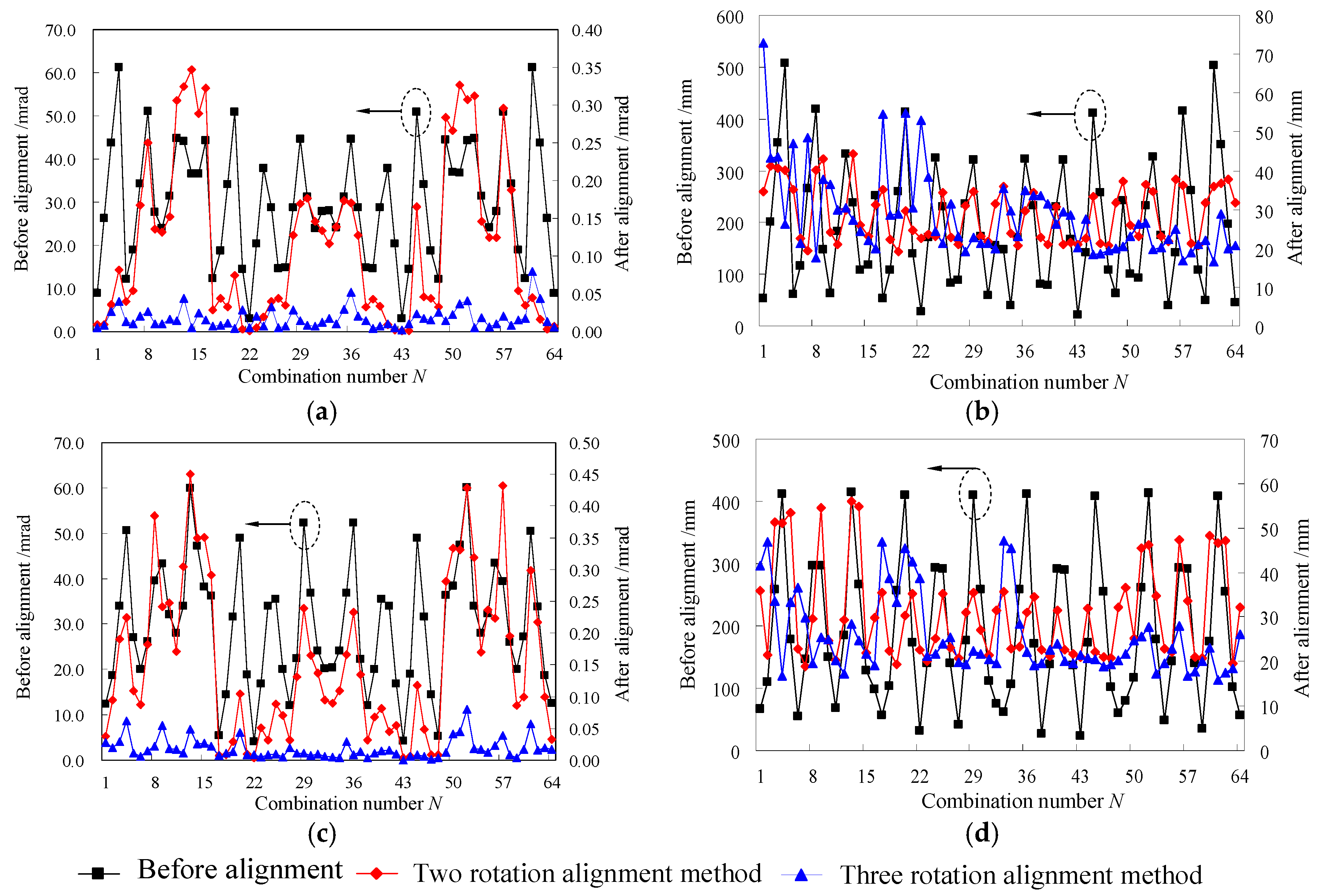
(3) Numerical simulation for mirror-facet alignment. The equivalent of facet 1 is adopted as the ABC rotation order (in Section 4) and the mirror-facet alignment adopts the CBA rotation order (in Section 5). The numerical results of the facet alignment in Parts 1 and 2 are shown in Figure 8.
The error angle θ of axis vector range is 0.001~0.080 mrad and 0.003~0.45 mrad (the error range was 2.950~61.190 mrad before alignment), by adopting the three-rotation and two-rotation alignment methods, respectively (Figure 8a,c). The results show that the alignment method has higher theoretical accuracy, which has verified their validity. The vertex position error of mirror unit can be greatly reduced by both methods but cannot be completely eliminated (Figure 8b,d). In Part 1, the error distance L was in the range 16.45~73.00 mm and 19.22~44.29 mm for the two-rotation and three-rotation methods, respectively (L ranged from 22.41 to 506.86 mm before alignment) (Figure 8b). To further reduce the vertex position error, the facet position of the mirror unit must be controlled before the initial installation. In this way, the vertex position error of the mirror unit can be effective controlled by real-time alignment using two visual measurement methods, which will be discussed in Section 7.
6.2. Experimental Alignment of the Plane Unit
6.2.1. Experimental Device and Process
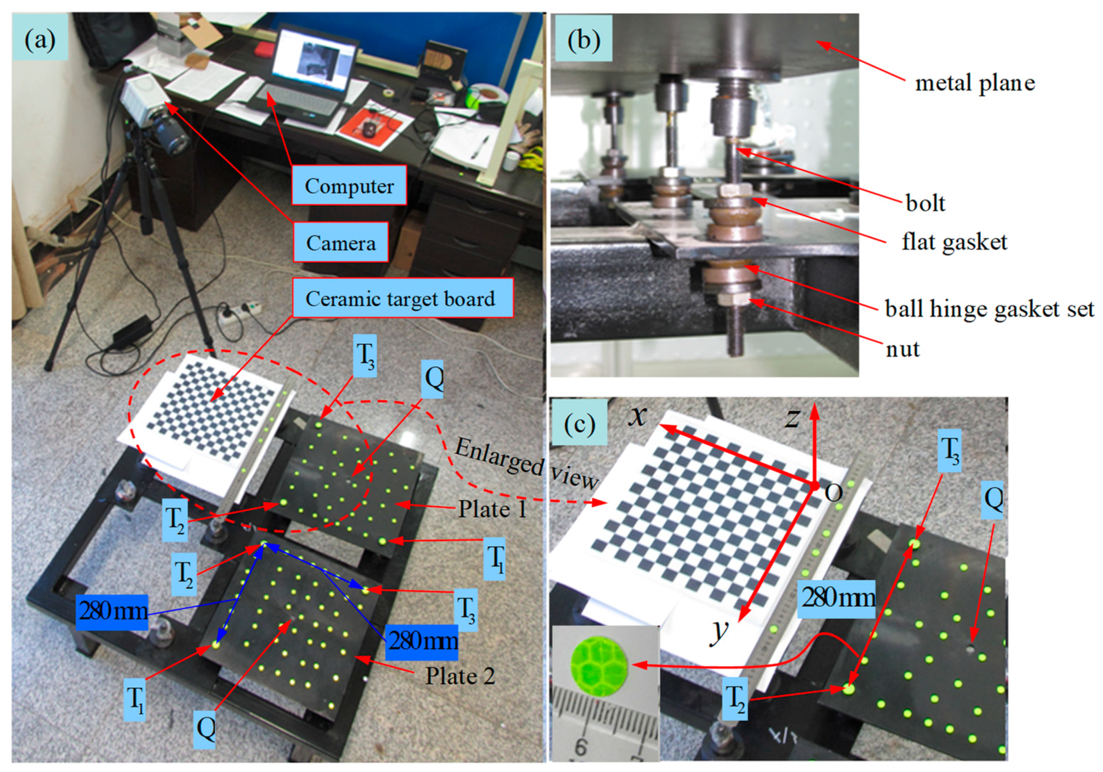
The experimental device for the facet alignment of the plane mirror was designed and developed to verify the effectiveness of the measurement and alignment methods presented in this paper (Figure 9). The experimental device was made up of a metal plane (Plate 1 and 2), camera (model: ORCA-Flash4.0 LT C11440-42U, sensor type: Scientific CMOS sensor FL-400, sensor size: 13.312 × 13.312 mm; image size: 2048 × 2048 pixels), a checkerboard target with a 20 × 20 mm square lattice and the accuracy of 0.002 mm for calibrating the internal and external camera parameters, and circular marks. The virtual plane mirror to be aligned in this experiment was created by milling the upper surface of the metal plane using a numerically-controlled machine. The support-adjust structure (Figure 9b) is the same as the structure in Figure 1. The diameter of the connection hole (d1) and bolt (d2) is 14.0 and 8.0 mm, respectively, and the thickness L1 of the connection plate is 5.0 mm. In the experiment, the metal plane was aligned using the three-rotation and two-rotation alignment method to move the metal plane parallel to the checkerboard target. In this process, the photogrammetric measurement coordinate system O-xyz was established on the checkerboard target (Figure 9).
To prepare the experiment, three circular markers made from a highly reflective material with a diameter of 16 mm were pasted on each metal plane, and the center point of each circular mark was regarded as a feature points T1, T2, and T3 as shown in Figure 9a. Then, a number of circular markers of diameter 10 mm were attached to the virtual mirror surface of the metal plane and used to determine the plane equation of the virtual mirror surface in this experiment. Briefly, the center point coordinate of each circular marker was measured by photogrammetry, then the plane equation of the virtual mirror in the metal plane was fitted by the least squares method using these points in order to verify the accuracy of the mirror facet measurement alignment methods. In ideal conditions, the coordinate of the ball-hinge center and feature point, as well as the axis vector and position vector of the vertex in plate 1 and 2 are known (in coordinate system O-xyz), as shown in Table 2.
Experimental process:
- (1)
- The checkerboard target and the two pieces of the metal plane were fixed in any alignment and the checkerboard target was kept fixed during the experiment.
- (2)
- The camera was used to take 32 photos from different views with the two metal planes and checkerboard target included in each photo.
- (3)
- Using the Camera alignment Toolbox in MatlabR2012a, the inside and outside parameters of the camera were calibrated [35].
- (4)
- The pixel coordinates of the center point of the circular marks in each photo were extracted, and then the global coordinates of each center point (in the O-xyz system) were calculated according to photogrammetry theory [33].
- (5)
- The facet parameters of the metal plane were calculated by one the translational two-rotation motion method (Section 3.2).
- (6)
- The three-rotation alignment method (Section 5.1) or two-rotation alignment method (Section 5.2) were used to calculate the adjusted values dA~dC of bolts 1~3, and metal plane was aligned according to the adjusted values.
- (7)
- Finally, the camera was used to take 16 photographs from different views to calculate the plane equation of the virtual mirror surface after alignment in order to verify the effects of the facet alignment. The results of the theoretical calculations along with the experimental measurements are presented in Table 3 and Table 4.
6.2.2. Results and Discussion
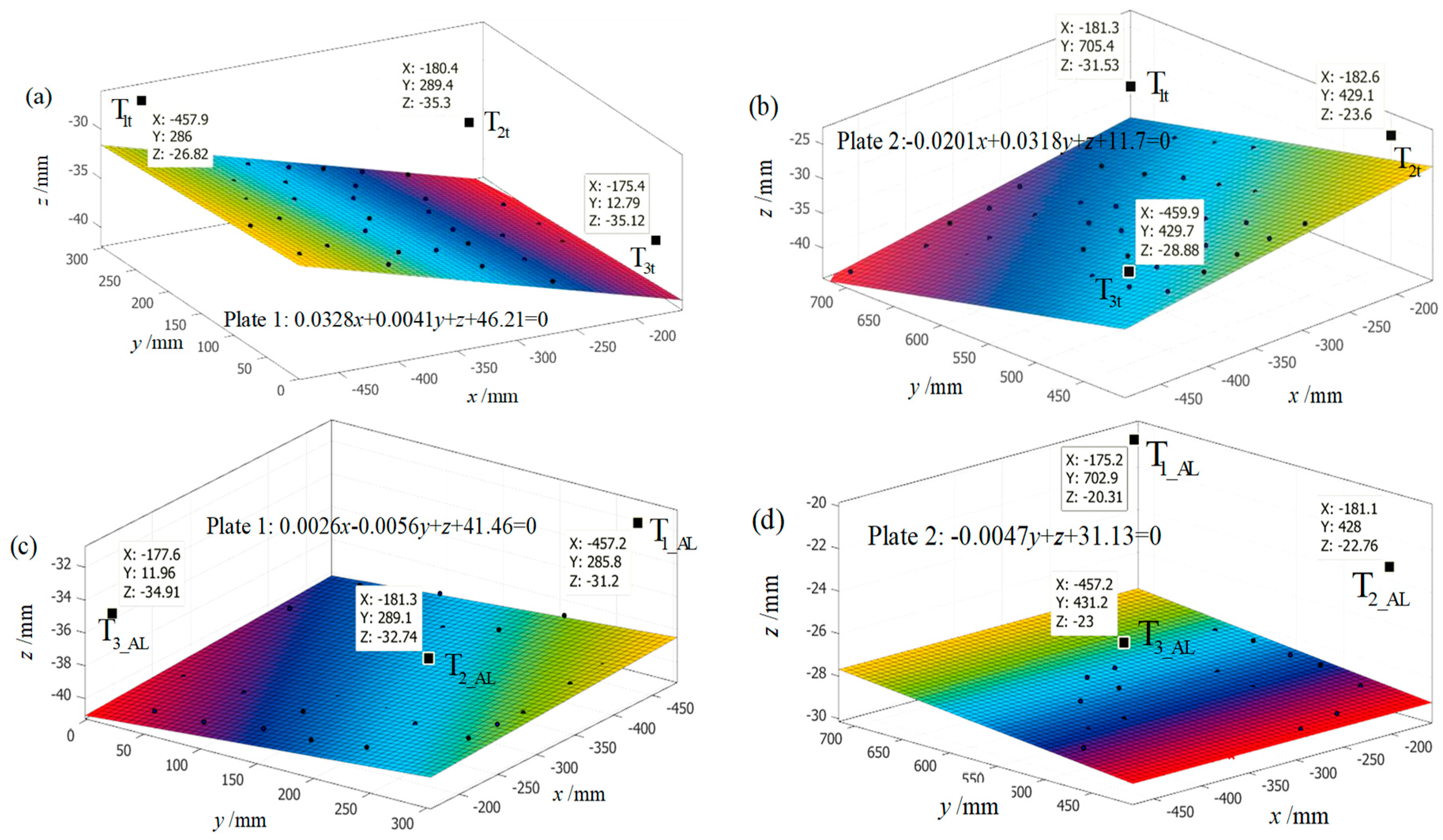
The experimental results by the three-rotation alignment method and two-rotation alignment method are as shown in Table 3 and Table 4. For the axis vector alignment of the metal plane, using the three-rotation and two-rotation alignment method can greatly improve facet alignment accuracy. Using the three-rotation alignment method, the error angle θ of the axis vector was decreased from 33.09 to 6.16 mrad and 37.59 to 4.69 mrad for plate 1 and 2, respectively (Table 3).Using the two-rotation alignment method, the error θ was decreased from 26.75 to 6.26 mrad and 46.11 to 2.05 mrad for Plate 1 and 2, respectively (Table 4). The fitted plane for plate 1 and 2 before and after adjustment is shown in Figure 10 and their fitted plane equation as shown in Equations (28)–(31) respectively, where Equations (28) and (29) is fitted plane equation of plate 1 and 2, respectively, before adjustment, and Equations (30) and (31) is fitted plane equation of plate 1 and 2, respectively, after adjustment. These normal vectors of the fitted planes are used for determining the axis vector of the metal plane as shown in Table 3.
For the facet alignment measurement of the metal plane, the intersection angle θerr between the normal vector of the fitting plane Nt1 and theoretically calculated Nt (using the mirror facet measurement method in Section 3) was 1.09 mrad in plate 1 (Table 3). Thus, the deviation between the normal vectors was very small. The results have shown that the mirror facet measurement method presented in this paper is valid. In the facet alignment experiment, the alignment accuracy of the metal plane mainly depended on the following factors: manufacture or installation error of the support-adjust structure (i.e., the position error of the ball-hinge center), positioning error of the feature points, spatial coordinate measurement errors of the feature points, and adjustment error of the bolt, therefore, the errors led to some deviation between the experimental results and theoretical values. To improve the accuracy of these methods in the application of mirror facet alignment method in a solar concentrator, control measures or reduction methods to minimize the above factors should be considered:
(1) The mirror units are usually made from precision molds, so the position accuracy of the ball-hinge center and the geometrical accuracy of the reflected mirror should be guaranteed.
(2) To reduce the positioning error of the feature points, a numerical control device could be used to accurately locate and attach the circular markers before the mirror manufacture, or three circular convex features could be included on the mirror unit surface in the initial design, such that the circular markers can be attached to the circular convex features after the mirror unit is made. Both methods could effectively control the positioning error of the feature points.
(3) The coordinate measurements of the feature points is the only field measurement in the entire mirror facet alignment process. Measurement errors directly affect calculation accuracy of the mirror facet and adjustment values of the bolt leading to reduced facet alignment accuracy of mirror unit. Fortunately, the current commercialized photogrammetry system is well developed and highly accurate, and these commercial photogrammetry systems could be used to improve the measurement accuracy of spatial coordinates.
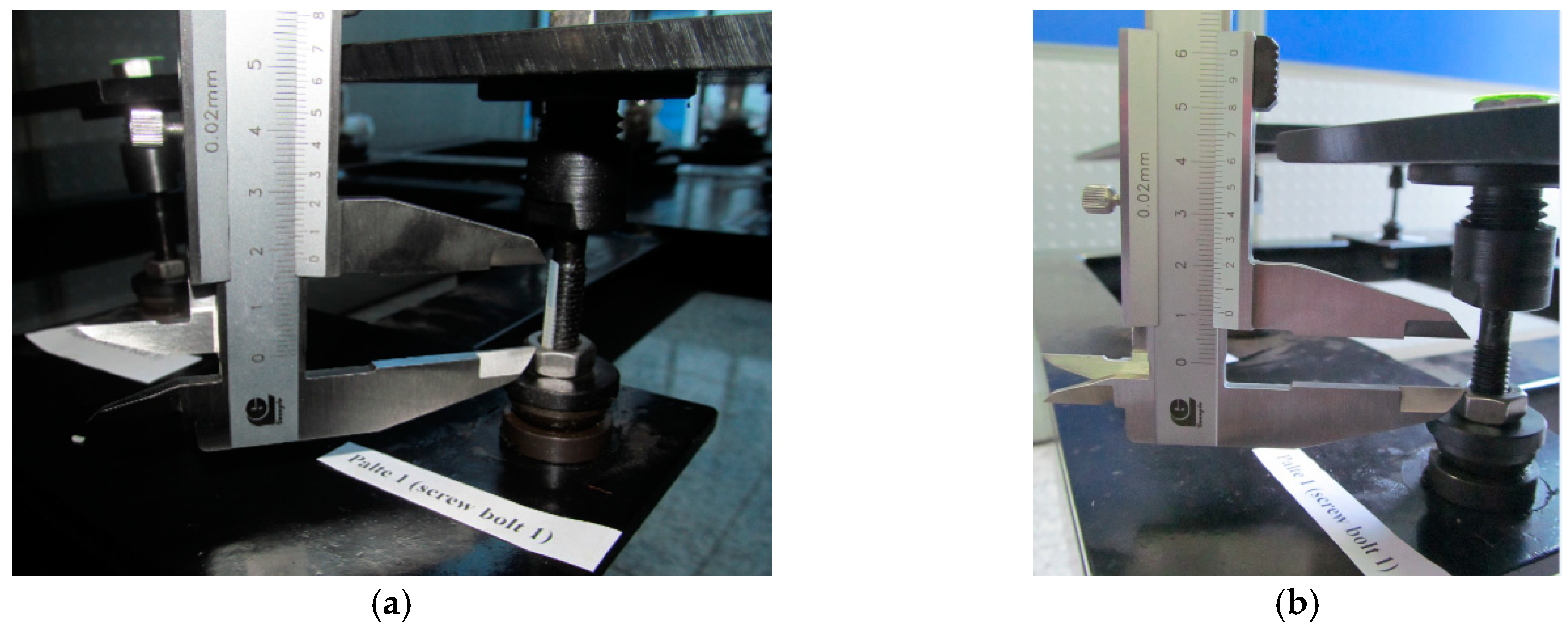
(4) The adjustment error of the bolt includes the theoretical calculation error and the adjustment control error. Theoretical calculation errors are caused by the assumptions made in Equations (20) and (23) and the adjustment control error of the bolt is the deviation between the actual movement value and the theoretically calculated adjustment value. In Figure 11, the adjustment control error of the bolt is shown to be approximately ±1.50 mm for the metal plane facet alignment experiment. Therefore, it is important to develop some type of device that can accurately control the adjustment of the bolt, or a new kind of support-adjust structure to conveniently and accurately control the bolt adjustment to be applied to the dish concentrator.
A typical mirror slope error (i.e., root-mean-square error, RMS) form the solar dish concentrator is evaluated and they are 2.66 and 2.50 mrad according to [22] and [26], respectively. Some methods of mirror alignment for solar concentrator are reviewed by Ren et al. [14], where the accuracy of mechanical alignment is as high as 1.5 mrad. According to [8], a typical mirror alignment error of the dish concentrator is 1.1 mrad. In this paper, the facet alignment accuracy was experimentally measured and found to be the range of 2.05~6.16 mrad and they are close to the mirror alignment accuracy given in the above literature. As such, the three-rotation and two-rotation alignment method proposed in this paper could effectively be used for mirror facet alignment in the dish concentrator system. Moreover, the alignment experiments in this work only adjusted the metal plate once. However there may be higher alignment accuracy if repeated adjustments were made. In addition, the advantage of the three-rotation and two-rotation alignment method presented is that the adjustment value and adjustment order for each support bolt could be determined prior to mechanical alignment of the mirror facet (aligning the axis vector error of mirror unit), which could provide quantitative adjustment information to the operator and avoid repeating the adjustment process, therefore reducing labor intensity. In addition, real-time adjustment information can be provided to operators while aligning the mirror facet by using two visual measurement methods [33,34], which would greatly improve the precision and efficiency of mirror installation in the dish concentrator (Section 7).
7. Future Work
For practical engineering applications, it is possible to measure the spatial coordinates of three feature points in “real time” using the two visual measurement methods [33,34]. The mirror facet alignment can as such be monitored and guide the mirror facet alignment to improve installation accuracy and efficiency of the mirror unit in a solar dish concentrator. This will involve:
(1) Real-time measurement of the spatial coordinates of three feature points on the mirror unit by using the two visual measurement methods, where the position parameters of two cameras are known in advance.
(2) The facet parameters of the mirror unit, adjustment values of the each support bolts, and error distance L after mirror alignment (theoretically calculated using Equation (18)) will be determined in real-time by the mirror facet calculation method (Section 3.2) and mirror facet alignment method (Section 5). These results will be displayed in real-time on the electronic screen.
(3) Alignment of the mirror facet by an operator will be performed according to the bolt adjustment values displayed on the screen. In this case, the real-time display of the facet parameters could reduce the position error of the vertex by allowing the operator to make adjustments to the initial facet alignment of the mirror unit. This will improve installation accuracy of the mirror unit and ensure good working efficiency.
8. Conclusions
In this paper, the facet installation measurement method and facet alignment method of the mirror unit of solar parabolic dish concentrator were presented and corresponding mathematical models were developed. The methods were verified by numerical simulation and an indoor experiment consisting of a metal plane facet alignment. The main conclusions of this study are as follows:
- The proposed mirror facet installation measurement method using photogrammetry only needs to measure the spatial coordinates of three feature points on the mirror surface (forming a triangle distribution) and can determine the facet alignment parameters of the mirror unit (axis vector and vertex position vector). The whole process is not only simple and convenient but does not cause optical pollution of the reflection mirror.
- The three-rotation alignment method (adjusting three support bolts in turn) and two-rotation alignment method (adjusting two of the three support bolts in turn) for aligning the mirror facet were presented. The advantage of these methods is that the adjustment value and adjustment order of each bolt can be determined prior to the alignment of the mirror facet, which could provide quantitative adjusting information to an operator. Theoretically, according to adjusting information just single aligning the mirror unit can eliminate the axis vector error of mirror unit, which can avoid the need for repeated adjustments, so could reduce labor costs.
- Using a numeral simulation for a case where the initial error range is 2.95~61.19 mrad before alignment, values for the error angle θ of axis vector range were found to be 0.001~0.08 mrad and 0.003~0.45 mrad by adopting the three-rotation and two-rotation alignment method, respectively. These results show that both methods are valid and have high theoretical accuracy.
- In the facet alignment experiments using a metal plane, the error angle θ decreased from 33.09 to 6.16 mrad and 37.59 to 4.69 mrad using three-rotation alignment methods and the error angles θ decreased from 26.75 to 6.26 mrad and 46.11 to 2.05 mrad using two-rotation alignment methods. The results have thus shown that the two methods can be used for mirror facet alignment in the solar concentrator.
- The position error of the vertex can be greatly reduced using facet alignment methods presented in this paper but cannot be completely eliminated. For engineering applications, the real-time display system of the facet installation measurement and facet alignment could be adopted to improve alignment accuracy (vertex position error could be effectively controlled) and efficiency of mirror units.
- In this paper, the presented methods for measuring facet alignment of the mirror unit are not subject to the geometry of the reflector mirror and therefore have extensive applicability. They could be applied to dish concentrator, solar tower, and trough concentrator and furthermore could provide a reference for the measurement and adjustment of rigid body facets in other engineering fields.
Author Contributions
Conceptualization, J.Y.; Methodology, J.Y., Y.P. and D.N.; Software, J.Y.; Validation, J.Y. and D.N.; Formal Analysis, J.Y.; Investigation, J.Y.; Data Curation, D.N.; Writing-Review & Editing, J.Y. All authors have read and agreed to the published version of the manuscript.
Funding
This work is supported by the National Natural Science Foundation of People’s Republic of China (No. 51641504), Hunan Province Natural Science Foundation of People’s Republic of China (No. 2019JJ50202, 2019JJ40085), and Scientific Research Project of Hunan Education Department (No. 19C0794, 18B565).
Acknowledgments
The authors specially acknowledge the editors and referees who made important comments to improve this article.
Conflicts of Interest
The authors declared no potential conflicts of interest with respect to the research, authorship, and/or publication of this article.
Nomenclature
| A, B, C | Position vectors of the ball hinge center (A, B and C) without installation error |
| N0 | Axis vector of the mirror facet without installation error |
| Q | Vertex position vector of the mirror facet without installation error |
| Nt | Axis vector of the mirror facet with installation error |
| Qt | Vertex position vector of the mirror facet with installation error |
| At, Bt, Ct | Position vector of the ball hinge center with installation error |
| T1,T2, T3 | Position vector of the feature points (T1, T2 and T3) without installation error |
| T1t,T2t, T3t | Position vector of the feature point with installation error |
| t1, t2, t3 | Position error vector of the feature point |
| n1, n2 | Vector of rotation axis of the mirror facet |
| , | Rotation angle of the mirror facet in OneT-TwoRmethod, mrad |
| , , | Rotation angle of the mirror facet in ThreeR-OneTmethod, mrad |
| M1 | Translational vector of the mirror facet, mm |
| NAL | Axis vector of the mirror facet after adjustments |
| QAL | Vertex position vector of the mirror facet after adjustments |
| AAL, BAL, CAL | Position vectors of the ball hinge center after adjustments |
| Error angle, mrad | |
| L | Error distance, mm |
| d1 | Diameter of the connection hole, mm |
| d2 | Diameter of the bolt, mm |
| L1 | Thickness of connection plate, mm |
| dA, dB, dC | Adjustment values of the bolt 1, 2 and 3 respectively, mm |
| DS-CSP | Dish-Stirling concentrated solar power system |
| OneT-TwoR | One translational and two rotational rigid body movement |
| ThreeR-OneT | Three rotation and one translational rigid body movement |
References
- Wang, H.; Huang, J.; Song, M.; Yan, J. Effects of receiver parameters on the optical performance of a fixed-focus Fresnel lens solar concentrator/cavity receiver system in solar cooker. Appl. Energy 2019, 237, 70–82. [Google Scholar] [CrossRef]
- Mancini, T.; Heller, P.; Butler, B.; Osborn, B.; Schiel, W.; Goldberg, V.; Buck, R.; Diver, R.; Andraka, C.; Moreno, J. Dish-Stirling systems: An overview of development and status. J. Sol. Energy Eng. 2003, 125, 135–151. [Google Scholar] [CrossRef]
- Coventry, J.; Andraka, C. Dish systems for CSP. Sol. Energy 2017, 152, 140–170. [Google Scholar] [CrossRef]
- Yan, J.; Peng, Y.-D.; Cheng, Z.R.; Liu, F.M.; Tang, X.H. Design and implementation of a 38 kW dish-Stirling concentrated solar power system. IOP Conf. Ser. Earth Environ. Sci. 2017, 93, 012052. [Google Scholar] [CrossRef] [Green Version]
- Yan, J.; Cheng, Z.R.; Peng, Y.D. Effects of geometrical parameters of a dish concentrator on the optical performance of a cavity receiver in a solar dish-Stirling system. Int. J. Energy Res. 2018, 42, 2152–2168. [Google Scholar] [CrossRef]
- Kussul, E.; Makeyev, O.; Baidyk, T.N.; Blesa, J.S.; Bruce, N.; Lara-Rosano, F. The Problem of Automation of Solar Concentrator Assembly and Adjustment. Int. J. Adv. Robot. Syst. 2011, 8, 150–157. [Google Scholar] [CrossRef] [Green Version]
- Lovegrove, K.; Burgess, G.; Pye, J. A new 500 m 2 paraboloidal dish solar concentrator. Sol. Energy 2011, 85, 620–626. [Google Scholar] [CrossRef] [Green Version]
- Xiao, G.; Yang, T.; Ni, D.; Cen, K.; Ni, M. A model-based approach for optical performance assessment and optimization of a solar dish. Renew. Energy 2017, 100, 103–113. [Google Scholar] [CrossRef]
- Yan, J.; Peng, Y.D.; Cheng, Z.R. Mirror rearrangement optimization for uniform flux distribution on the cavity receiver of solar parabolic dish concentrator system. Int. J. Energy Res. 2018, 42, 3588–3614. [Google Scholar] [CrossRef]
- Yan, J.; Peng, Y.D.; Cheng, Z.R. Optimization of a discrete dish concentrator for uniform flux distribution on the cavity receiver of solar concentrator system. Renew. Energy 2018, 129, 431–445. [Google Scholar] [CrossRef]
- Andraka, C.E.; Yellowhair, J.; Trapeznikov, K.; Carlson, J.; Myer, B.; Stone, B.; Hunt, K. AIMFAST: An alignment tool based on fringe reflection methods applied to dish concentrators. J. Sol. Energy Eng. 2011, 133, 031018. [Google Scholar] [CrossRef] [Green Version]
- Yan, J.; Cheng, Z.R.; Peng, Y.D. Effect of tracking error of double-axis tracking device on the optical performance of solar dish concentrator. Int. J. Photoenergy 2018, 2018, 1–13. [Google Scholar] [CrossRef] [Green Version]
- Xiao, J.; Wei, X.; Lu, Z.; Yu, W.; Wu, H. A review of available methods for surface shape measurement of solar concentrator in solar thermal power applications. Renew. Sustain. Energy Rev. 2012, 16, 2539–2544. [Google Scholar] [CrossRef]
- Ren, L.; Wei, X.; Lu, Z.; Yu, W.; Xu, W.; Shen, Z. A review of available methods for the alignment of mirror facets of solar concentrator in solar thermal power system. Renew. Sustain. Energy Rev. 2014, 32, 76–83. [Google Scholar] [CrossRef]
- Bulnes, C.A.A.; Peña-Cruz, M.I.; Mutuberría, A.; Diaz-Uribe, R.; Sánchez-González, M. A survey of methods for the evaluation of reflective solar concentrator optics. Renew. Sustain. Energy Rev. 2017, 69, 673–684. [Google Scholar] [CrossRef]
- Jones, S.A.; Neal, D.R.; Gruetzner, J.K.; Houser, R.M.; Edgar, R.M.; Wendelin, T.J. VSHOT: A Tool for Characterizing Large, Imprecise Reflectors; Sandia National Labs: Albuquerque, NM, USA, 1996.
- Jones, S.A. VSHOT Measurements of Distal II Dish Concentrators; Sandia National Labs: Albuquerque, NM, USA, 1999.
- Maccari, A.; Montecchi, M. An optical profilometer for the characterisation of parabolic trough solar concentrators. Sol. Energy 2007, 81, 185–194. [Google Scholar] [CrossRef]
- Diver, R.B. Mirror Alignment and Focus of Point-Focus Solar Concentrators (No. SAND--94-2638C; CONF-950336--7); Sandia National Labs: Albuquerque, NM, USA, 1994.
- Steffen, B.J.; Andraka, C.E.; Diver, R.B. Development and Characterization of a Color 2f Alignment Method for the Advanced Dish Development System. In Proceedings of the ASME 2003 International Solar Energy Conference, Kohala Coast, HI, USA, 15–18 March 2003; American Society of Mechanical Engineers: New York, NY, USA, 2003; pp. 657–663. [Google Scholar]
- Andraka, C.E.; Diver, R.B.; Rawlinson, K.S. Improved Alignment Technique for Dish Concentrators. In Proceedings of the ASME 2003 International Solar Energy Conference, Kohala Coast, HI, USA, 15–18 March 2003; American Society of Mechanical Engineers: New York, NY, USA, 2003; pp. 625–635. [Google Scholar]
- Ulmer, S.; Heller, P.; Reinalter, W. Slope measurements of parabolic dish concentrators using color-coded targets. J. Sol. Energy Eng. 2008, 130, 011015. [Google Scholar] [CrossRef]
- Shortis, M.R.; Johnston, G.H.G. Photogrammetry: An available surface characterization tool for solar concentrators, Part I: Measurements of surfaces. J. Sol. Energy Eng. 1996, 118, 146–150. [Google Scholar] [CrossRef]
- Shortis, M.R.; Johnston, G.H.G. Photogrammetry: An available surface characterization tool for solar concentrators, part II: Assessment of surfaces. J. Sol. Energy Eng. 1997, 119, 286–291. [Google Scholar] [CrossRef]
- Burgess, G.; Shortis, M.; Kearton, A.; Garzoli, J. Photogrammetry for Dish Concentrator Construction; James Cook University: Townsville, Australia, 2009; pp. 1–10. [Google Scholar]
- Blázquez, R.; Carballo, J.A.; Cadiz, P.; Frasquet, M.; Silva-Pérez, M.; Fontela, P.; Ballesteros, J. Optical test of the DS1 prototype concentrating surface. Energy Procedia 2015, 69, 41–49. [Google Scholar] [CrossRef] [Green Version]
- Forman, P.; Müller, S.; Ahrens, M.A.; Schnell, J.; Mark, P.; Höffer, R.; Hennecke, K.; Krüger, J. Light concrete shells for parabolic trough collectors–Conceptual design, prototype and proof of accuracy. Sol. Energy 2015, 111, 364–377. [Google Scholar] [CrossRef]
- Marz, T.; Prahl, C.; Ulmer, S.; Wilbert, S.; Weber, C. Validation of two optical measurement methods for the qualification of the shape accuracy of mirror panels for concentrating solar systems. J. Sol. Energy Eng. 2011, 133, 031022. [Google Scholar] [CrossRef]
- Skouri, S.; Ali, A.B.H.; Bouadila, S.; Ben Nasrallah, S. Optical qualification of a solar parabolic concentrator using photogrammetry technique. Energy 2015, 90, 403–416. [Google Scholar] [CrossRef]
- King, P.; Comley, P.; Sansom, C. Parabolic trough surface form mapping using photogrammetry and its validation with a large Coordinate Measuring Machine. Energy Procedia 2014, 49, 118–125. [Google Scholar] [CrossRef] [Green Version]
- Li, L.; Dubowsky, S. A new design approach for solar concentrating parabolic dish based on optimized flexible petals. Mech. Mach. Theory 2011, 46, 1536–1548. [Google Scholar] [CrossRef]
- Chipperfield, A.J.; Fleming, P.J. The MATLAB genetic algorithm toolbox. In Proceedings of the IEE Colloquium on Applied Control Techniques Using MATLAB, London, UK, 26 January 1995. [Google Scholar]
- Ma, S.D.; Zhang, Z.Y. Computer Vision; Science Press: Beijing, China, 1998; pp. 52–94. (In Chinese) [Google Scholar]
- Wen, X.; Song, K.; Niu, M.; Dong, Z.; Yan, Y. A three-dimensional inspection system for high temperature steel product surface sample height using stereo vision and blue encoded patterns. Opt. Int. J. Light Electron. Opt. 2017, 130, 131–148. [Google Scholar] [CrossRef]
- Bouguet, J.Y. Camera Calibration Toolbox for Matlab. Available online: http://www.vision.caltech.edu/bouguetj/calib_doc/ (accessed on 15 October 2019).
Figure 1.
(a) Photograph of the 38 kW dish-Stirling solar thermal power system (38 kW XEM-Dish System), (b) Image of the posterior side of the mirror unit, (c) image of the support-adjust structure on the back of the mirror unit, and (d) schematic of the assembly model of the support-adjust structure.

Figure 2.
Diagram of the facet parameters and measurements of the parabolic mirror unit.

Figure 3.
The mirror unit through OneT-TwoR rigid body motion as it moves from the ideal facet to facet 1 by (a) translational motion, (b) rotation around point T1t, and (c) rotation about axis T1t T3t.
Figure 3.
The mirror unit through OneT-TwoR rigid body motion as it moves from the ideal facet to facet 1 by (a) translational motion, (b) rotation around point T1t, and (c) rotation about axis T1t T3t.

Figure 4.
The three rotational motions of the mirror unit in order ABC consist of: (a) rotation about axis CB, (b) rotation about axis , and (c) rotation about axis .
Figure 4.
The three rotational motions of the mirror unit in order ABC consist of: (a) rotation about axis CB, (b) rotation about axis , and (c) rotation about axis .

Figure 5.
The three-rotation alignment process of the mirror unit consists of: (a) rotation about axis AtBt, (b) rotation about axis CALAt, and (c) rotation about axis BALCAL.
Figure 5.
The three-rotation alignment process of the mirror unit consists of: (a) rotation about axis AtBt, (b) rotation about axis CALAt, and (c) rotation about axis BALCAL.

Figure 6.
The movement of bolt 3 during facet alignment of the mirror unit: (a) Schematic drawing showing the geometric parameters of bolt 3 and their movements and (b) Diagram showing the maximum deflection angle βmax = 2β1.
Figure 6.
The movement of bolt 3 during facet alignment of the mirror unit: (a) Schematic drawing showing the geometric parameters of bolt 3 and their movements and (b) Diagram showing the maximum deflection angle βmax = 2β1.

Figure 7.
Flowchart of the three-rotation alignment method for aligning the axis vector of single mirror unit in the dish concentrator.
Figure 7.
Flowchart of the three-rotation alignment method for aligning the axis vector of single mirror unit in the dish concentrator.

Figure 8.
The numerical results of the facet alignment of the mirror unit using two-rotation and three-rotation alignment methods (from Parts 1 and 2): (a) error angle θ of the axis vector in Part 1, (b) error distance L of the vertex in Part 1, (c) error angle θ of the axis vector in Part 2, and (d) error distance L of the vertex in Part 2.

Figure 9.
Experimental device for the facet alignment of a metal plane. (a) Experimental system, (b) support bolt structure and (c) circular markers.
Figure 9.
Experimental device for the facet alignment of a metal plane. (a) Experimental system, (b) support bolt structure and (c) circular markers.

Figure 10.
The fitted equation of metal plane (Plate 1 and 2) before and after the adjustment using the three-rotation alignment method: (a,b) before adjustment, (c,d) after adjustment.
Figure 10.
The fitted equation of metal plane (Plate 1 and 2) before and after the adjustment using the three-rotation alignment method: (a,b) before adjustment, (c,d) after adjustment.

Figure 11.
The support distance of bolt 1 before and after alignment in Plate 1 using the three-rotation alignment method: (a) before alignment, distance is 18.40 mm and (b) after alignment, distance is 10.82 mm.
Figure 11.
The support distance of bolt 1 before and after alignment in Plate 1 using the three-rotation alignment method: (a) before alignment, distance is 18.40 mm and (b) after alignment, distance is 10.82 mm.


Table 1.
Coordinates of the ball-hinge centers, feature points and facet parameters of Part 1 and Part 2.
Table 1.
Coordinates of the ball-hinge centers, feature points and facet parameters of Part 1 and Part 2.
| Mirror Unit | Coordinate of Ball Hinge Centers | Coordinate of Feature Points | Facet Parameters |
|---|---|---|---|
| Part 1 | A = [8454.16, 1881.66, 1863.21] | T1 = [8454.16, 1881.66, 1863.21] | N0 = [0, 0, 1.0] |
| B = [8633.81, 104.03, 1839.79] | T2 = [8633.81, 104.03, 1839.79] | Q = [0, 0, 0] | |
| C = [7638.40, 906.52, 1456.55] | T3 = [7638.40, 906.52, 1456.55] | ||
| Part 2 | A = [8454.16, 1881.66, 1863.21] | T1 = [8454.16, 1881.66, 1863.21] | N0 = [0, 0, 1.0] |
| B = [8633.81, 104.03, 1839.79] | T2 = [8633.81, 104.03, 1839.79] | Q = [0, 0, 0] | |
| C = [7695.98, 104.03, 1435.85] | T3 = [7695.98, 104.03, 1435.85] |
Table 2.
Coordinates of the ball-hinge centers, feature points and facet parameters of Plate 1 and 2.
Table 2.
Coordinates of the ball-hinge centers, feature points and facet parameters of Plate 1 and 2.
| Metal Plane | Coordinate of Ball Hinge Centers | Coordinate of Feature Points | Facet Parameters |
|---|---|---|---|
| Plate 1 | A = [−460.0, 290.0, −65.0] | T1 = [−460.0, 290.0, −33.5] | N0 = [0, 0, 1.0] |
| B = [−180.0, 290.0, −65.0] | T2 = [−180.0, 290.0, −33.5] | Q = [−320.0, 150.0, −40.0] | |
| C = [ −180.0, 10.0, −65.0] | T3 = [−180.0, 10.0, −33.5] | ||
| Plate 2 | A = [−180.0, 710.0, −65.0] | T1 = [−180.0, 710.0, −33.5] | N0 = [0, 0, 1.0] |
| B = [−180.0, 710.0, −65.0] | T2 = [−180.0, 710.0, −33.5] | Q = [−320.0, 470.0, −40.0] | |
| C = [−180.0, 430.0, −65.0] | T3 = [−180.0, 430.0, −33.5] |
Table 3.
Experimental data from the facet alignment of the metal plane using the three-rotation alignment method.
Table 3.
Experimental data from the facet alignment of the metal plane using the three-rotation alignment method.
| Metal Plane | Before Alignment (Measurement Value) | OneT−TwoR Method (Section 3.2) (Theoretical Value) | Three−Rotation Alignment Method (Theoretical Value) | After Alignment (Measurement Value) |
|---|---|---|---|---|
| Plate 1 | Nt1 = [0.0328, 0.0041, 1.0] | Nt = [0.0333, 0.0031, 0.9994] | NAL1 = [0.0026, −0.0056, 1.0] | |
| θ = 33.09 mrad | θ = 33.47 mrad | θ = 0.43 mrad | θ = 6.16 mrad | |
| T1t = [−457.90, 286.00, −26.82] | Θerr = 1.09 mrad | dA = 7.89 mm | ||
| T2t = [−180.40, 289.40, −35.30] | dB = −1.45 mm | |||
| T3t = [−175.40, 12.79, −35.12] | dC = −0.62 mm | |||
| Plate 2 | Nt1 = [−0.0201, 0.0318, 1.0] | Nt = [−0.0145, 0.0325, 0.9994] | NAL1 = [0, −0.0047, 1.0] | |
| θ = 37.59mrad | θ=35.62 mrad | θ = 0.13 mrad | θ = 4.69 mrad | |
| T1t = [−183.30, 705.40, −31.53] | θerr=5.67 mrad | dA = −8.70 mm | ||
| T2t = [−182.60, 429.10, −23.60] | dB = 0.40 mm | |||
| T3t = [−458.90, 429.70, −28.88] | dC = −3.76 mm |
Note: The angle θ is the intersection angle between the measurement result (Nt1 or NAL1) or theoretical calculation result (Nt) and ideal axis vector N0 (N0 = [0, 0, 1.0]); the angle θerr is the intersection angle between the measurement result (Nt1) and theoretical calculation result (Nt).
Table 4.
Experimental results of the facet alignment of the metal plane using the two-rotation alignment method.
Table 4.
Experimental results of the facet alignment of the metal plane using the two-rotation alignment method.
| Metal Plane | Before Alignment (Measurement Value) | OneT−TwoR Method (Section 3.2) (Theoretical Value) | Two−Rotation Alignment Method (Theoretical Value) | After Alignment (Measurement Value) |
|---|---|---|---|---|
| Plate 1 | Nt1 = [−0.0142, 0.0227, 1.0] | Nt = [−0.0143, 0.0285, 0.9995] | NAL1 = [−0.0009, −0.0062, 1.0] | |
| θ = 26.75 mrad | θ = 31.79 mrad | θ = 0.45 mrad | θ = 6.26 mrad | |
| T1t = [−460.60, 287.10, −38.21] | Θerr = 5.82 mrad | dA = −11.99 mm | ||
| T2t = [−182.00, 289.80, −32.99] | dB = −7.99 mm | |||
| T3t = [177.70, 12.20, −26.35] | dC = 0 mm | |||
| Plate 2 | Nt1 = [−0.0432, 0.0162, 1.0] | Nt = [−0.0465, 0.0175, 0.9988] | NAL1 = [0.0019, 0.0008, 1.0] | |
| θ = 46.11 mrad | θ = 49.68 mrad | θ = 0.32 mrad | θ = 2.05 mrad | |
| T1t = [−176.60, 704.20, −26.65] | θerr = 3.52 mrad | dA = 8.12 mm | ||
| T2t = [−182.70, 428.40, −23.09] | dB = 13.01 mm | |||
| T3t = [−460.00, 433.60, −34.71] | dC = 0 mm |
© 2020 by the authors. Licensee MDPI, Basel, Switzerland. This article is an open access article distributed under the terms and conditions of the Creative Commons Attribution (CC BY) license (http://creativecommons.org/licenses/by/4.0/).
Share and Cite
MDPI and ACS Style
Yan, J.; Peng, Y.; Nie, D. A Method for the Installation Measurement and Alignment of a Mirror Unit in the Solar Dish Concentrator. Appl. Sci. 2020, 10, 1511. https://0-doi-org.brum.beds.ac.uk/10.3390/app10041511
AMA Style
Yan J, Peng Y, Nie D. A Method for the Installation Measurement and Alignment of a Mirror Unit in the Solar Dish Concentrator. Applied Sciences. 2020; 10(4):1511. https://0-doi-org.brum.beds.ac.uk/10.3390/app10041511
Chicago/Turabian StyleYan, Jian, Youduo Peng, and Duzhong Nie. 2020. "A Method for the Installation Measurement and Alignment of a Mirror Unit in the Solar Dish Concentrator" Applied Sciences 10, no. 4: 1511. https://0-doi-org.brum.beds.ac.uk/10.3390/app10041511
Note that from the first issue of 2016, this journal uses article numbers instead of page numbers. See further details here.