Article

Control System Applied to the Microinjection of Artificial Tears for Severe Dry Eye Treatment

by
Narcisse Meni-Babakidi
,
Gonzalo Viramontes-Gamboa
*,
Laura Alicia Ibarra-Bracamontes
and
Israel Luna-Reyes
Graduate Program in Physical Engineering, Universidad Michoacana de San Nicolás de Hidalgo, 403 Santiago Tapia, Morelia 58000, Mexico
*
Author to whom correspondence should be addressed.
Submission received: 6 February 2020 / Revised: 28 February 2020 / Accepted: 6 March 2020 / Published: 10 March 2020
(This article belongs to the Special Issue Biomicrofluidic Systems for Diagnostics and Clinical Applications)

Abstract

:
This paper presents a portable automated teardrop microinjection system as a practical solution for patients suffering from severe dry eye. The electronic device for the controlled and continuous injection of artificial tears is designed, assembled, and tested for performance and stability. It is controlled via Wi-Fi from an Android programmable device. Its design is based on the physicochemical properties of artificial tears, and with both production costs and portability in mind. The system was modeled according to the V methodology of the association for professional German engineers VDI 2206 standard. The microinjector handles a wide range of internal variables such as tears flow rate (0.13 to 60 μL/min), tears viscosity (up to 600 Pa·s), temperature (up to 60 °C), injected volume of tears, and time between consecutive injections. For evaluation purposes, a comprehensive set of experimental tests were carried out to the system, comparing the actually delivered amount of tears, flow rate, and prescribed time vs. programmed values, the error was ∼0.2% for commercially available artificial tears.

Graphical Abstract

1. Introduction

Dry eye syndrome occurs when the lachrymal system loses its capacity to lubricate the ocular surface. Several symptoms are then observed, which range from continuous ocular globe burning to (in some cases) severe decreasing of visual capabilities [1,2]. It has been estimated that between 5% and 30% of the population suffers from dry eye [3], the Asian population being the most susceptible. Along the years there have been many efforts to generate reliable statistics on the prevalence of dry eye syndrome, unfortunately with significant differences between them. It is possible to find reports for Europe [4], United Sates of America [5,6], Africa [7], China [8], India [9], Ecuador [10], Canada [11], Japan [12], and Germany [13], among other countries. Unfortunately most countries remains poorly studied. In 2017 an international epidemiology subcommittee of the Tear Film and Ocular Surface Society summarized all available information and statistics related to dry eye [14], some general trends are common to the different studies, the prevalence of dry eye increases with age, above 50 years old women are more prone than men (∼70% vs. ∼30%), being a part of the Asian population, with around 32% of incidence in adult age is more susceptible than Caucasian (1% to 20%). Some countries in Africa have an incidence above 40%. Hispanics have an incidence 1.8 times higher than Caucasians. Dry eye disease currently has no cure [15]; a generalized palliative remedy worldwide is the manual drop application of artificial tears [16] to keep the ocular surface wet. Indeed, the manual drip method is very simple and effective in most cases, however some drawbacks may occur, as in some patients it is not possible to place drops of artificial tears with the same frequency [17], which dismisses the efficiency of the treatment and becomes a tedious practice. German et al. [18] obtained evidence that droppers are not a very reliable method for applying artificial tears. Different tips of droppers have different dimensions and, therefore, deliver different volumes of medication. This variation can cause treatment inefficiency or side effects. Because there is no standard implemented for the amount of drops volume that should be dispensed by the tip of a dropper, the droppers are not completely reliable for the treatment of ocular dryness disease. Additionally, some approaches dispense an inaccurate amount of drops in the prescribed time [19]. Self-administration is also difficult for elderly people, children, and patients suffering from mobility medical disorders, like Parkinson’s disease or arthritis. As a consequence, the irregularity in patient compliance with medical instructions may compromise the effectiveness of the treatment.
In healthy individuals, the human tear system lubricates the eye at flow rates from 2 to 5 μL/min [20,21,22], with tear film breaking down at times normally lasting from 10 to 15 s [23,24]. In individuals suffering of severe dry eye syndrome, the tear film tends to evaporate in less than a second [23,25], causing a permanent burning sensation, and consequently a critical decrease in vision and life quality. There are devices allowing patients to self-administer artificial tears easily and semi-automatically, they include implants inserted under the skin [26] and devices placed in the conjunctival sac of the eye [27]. Nevertheless, such devices are invasive, prone to contaminates, and may become impractical. In this study, an alternative noninvasive microinjection system of artificial tears is presented, with significant advantages for the disabled, the arthritic, people with Parkinson’s disease, the elderly, people immobilized temporarily or permanently by different medical situations or diseases, extreme cases of people with amputated hands or fingers, etc., and even for individuals having no problems using the manual drop, but find the device useful to improve their quality of life. It combines a set of mechanical, electronic, and software components that allow the user the automated administration of tears according to his personal needs. The user controls every variable, like the volume of tears to be injected and the injection frequency, from his Android-based cell phone. Essentially, the piston of a toothed syringe containing artificial tears is coupled to a stepper motor through gears, which pushes the syringe content through a biocompatible silicone cylindrical capillary to the patient’s eyelids commissure. The engine is controlled through a programmable microprocessor that has a Wi-Fi module for wireless control. The proposed system guarantees the injection of artificial tears without altering its medical characteristics, it is useful to treat eye diseases that require continuous and controlled tears injection. The main application is then focused on patients suffering severe dry eye syndrome and/or people with motor disabilities.
The remainder of the paper is organized as follows: Section 2 presents the mathematical foundations of fluids mechanics relevant to microinjection in cylindrical capillaries. Section 3 describes the technical characteristics of the used electronic components, materials, and methods. Section 4 presents the design and assembly of the device as well as the user-friendly interactive Android-based interface. Section 5 explains how the device should be set up by the users. Section 6 discusses the results of the performance and functionality tests. Finally Section 7 provides some final conclusions.

2. Foundations

The physicochemical variables of the tear film that have been reported to change in dry eye patients are: (a) zero-shear viscosity values of 4.4, 7.1, and 8.3 mPa·s for normal tears, and 27.1 and 31.1 mPa·s for dry-eye tears [28]; (b) pH, 7.51 ± 0.18 for normal eye vs. 7.62 ± 0.19 for dry eye [29]; (c) surface tension, for normal eyes 43.6 ± 2.7 mN/m and for dry eyes 49.6 ± 2.2 mN/m [30]; (d) osmolarity, 296.5 ± 9.8 Osm / m 3 for normal eye, increasing gradually to 318 Osm / m 3 for severe dry eye [31]. From these variables, the effect of the viscosity of artificial tears and its relevance to dry eye has been the most studied [32], and it is the only one relevant to the design of the device.
The presented microinjector pushes the viscous artificial tears from an internal reservoir up to patients eyes through a cylindrical capillary of constant length L and diameter d. The viscosity of different commercially available formulas of artificial tears was reported [32], it varies within a width range of values, from 1 up to 600 Pa·s, which are generally higher than 1.5 × 10 3 Pa·s, the viscosity for natural tears measured originally by Tiffany et al. [28]. This wide variation in viscosity imposes a problem of power estimation that the electromechanical device must provide to be able to manage the tear flows required by the patient. The minimum working power delivered by the microinjector can be theoretically estimated solving the Navier–Stokes equations. Fortunately the problem of viscous fluids dynamics in cylindrical capillaries has an exact analytical solution and may be found elsewhere [33,34]. Given the relevance of delivered power in the design of electromechanical devices the calculus is presented below, the selected engine needs to at least deliver this power to overcome the viscous forces.

2.1. Hagen–Poiseuille Flow

Artificial tears density, viscosity, and Reynolds numbers are the properties relevant for the design of the microinjector. The density of artificial tears is practically the same as water since they are aqueous solutions with different soluble molecules at very low concentrations (e.g., 0.02%). For practical purposes and theoretical estimations, it is taken as 1.0 gr / cm 3 .
Artificial tears viscosity, unlike density, is highly dependent on chemical composition and varies considerably between different commercial formulas. Bhojwani et al. [32] reported measured values from 1 up to ∼600 Pa·s of dynamic viscosity for common high viscosity and low viscosity artificial tears at temperatures from 25 to 37 °C. Lievens et al. [35] and Bhojwani et al. [32] presented studies to determine the effect of tears viscosity on well-being in dry eye patients, and reported a slight improvement with the increase of viscosity, while some others reported no improvements at all.
The present microinjector emulates the flow produced by the human tear system, normally ranging from 2 to 7 mL/day of organic lubricant [36]. Taking into account the range of experimental viscosities reported by Bhojwani [32], the flows handled by the microinjector, the density of artificial tears, and the internal diameter of convenient commercially available capillaries (∼275 to ∼800 μm), the Reynolds numbers involved are very small, ∼ 5.0 × 10 7 to ∼ 3.0 × 10 4 , so the flow of artificial tears from our microinjection system is laminar.
In the microinjector, the shape of all tubes and capillaries involved are cylindrical and the flow is pressure driven only. Under these conditions, the flow of artificial tears is described by the well known Hagen–Poiseuille flow. The solution in cylindrical coordinates r , θ , z of the Navier–Stokes equations for this flow may be found elsewhere [33,37]. The radial and angular components of the velocity are independent of both θ and z and null, then v r r = 0 , v θ r = 0 and v z = v z r . Velocity gradients in θ and z are also zero. Under these conditions, the final result for v z ( r ) and the pressure driven flow, Q, are:
v z = 1 4 μ p z R 2 r 2
and
Q = π R 2 8 μ p z
where μ is the dynamic viscosity, p is pressure, R is the capillary radius, and p / z is the pressure gradient. This is the well known result empirically found by Poiseuille [38] and Hagen [39].
For practical purposes, it will be the dry eye patient whom, according to his needs, establishes the flow Q of artificial tears that he needs to feel better in the microinjector, as noticed, the human lubricating system works with Q = 1 to 5 μ L / min . Then Equation (2) is useful to calculate the exact minimum pressure gradient needed to keep the user-required flow, which will be applied by the engine of the device.

2.2. Theoretical Determination of Power

The power spent (consumed or delivered) for a viscous liquid is the energy dissipated by the friction (e.g., heat) per unit of time. For catheters and capillaries the power P is computed by
P = Ω H Q 2 ,
where Ω H is the hydrodynamic resistance, a parameter that only depends on the shape of the pipe and the viscosity of the fluid and measures the difficulty for a fluid to circulate through a pipe. For a cylindrical capillary it is given by Pisano [34]
Ω H = 8 μ L π R 4 ,
where L is the capillary length. Substitution of typical flow rates to be used by patients ( 0.13 to 60 μ L / min ), capillary radius ( 125 to 400 μ m ), and length (60 cm) as well as artificial tears viscosities (1 to 600 Pa·s) in Equation (3) gives viscous power in the order of 16 nW to 3.7 W. In order to determine the minimum power of the device’s engine, it will be necessary to add to this theoretical minimum the power required to overcome the rest of mechanical frictional forces, like the one between the piston and the syringe’s wall. In Section 6 the frictional power due to forces other than viscosity is measured experimentally.

3. Materials and Methods

3.1. Electronic Components and Accessories

The following electronics, electrical components (Figure 1), and accessories were used for the construction of the microinjector of artificial tears: the microcontroller ESP8266EX with ESP-12 Wi-Fi Module, IC Hex-Inverter 74HC04D, Voltage Regulators KIA1117-3.3 and AMS1117-5.0, IC L293DD, Aiyima 15 Stepping MicroGear Motor, switch button, biocompatible silicone capillary, syringe, user selected or prescribed glasses, device case, and a 9 V rechargeable battery. The technical specifications of each components are presented below.
The Microcontroller ESP8266EX with ESP-12 Wi-Fi Module manufactured by Espressif Systems (Figure 1a) configures its parameters through a WEB page, which runs in a HOST in the microcontroller, which also has Wi-Fi capability and host- or client-type configuration. Besides, it includes an antenna, switches, power amplifiers, low-noise amplifier receivers, and power management modules (technical specifications are in Table S1 of Supplementary Material).
The L293DD integrated circuit from Texas Instruments (Figure 1e) is designed to drive a wide array of inductive loads such as relays, solenoids, DC and bipolar stepping motors, as well as other high-current and high-voltage loads. All inputs are TTL compatible and tolerant up to 7 V. Each output is a complete totem-pole drive circuit, with a Darlington transistor sink and a pseudo-Darlington source. Drivers are enabled in pairs, with drivers 1 and 2 enabled by 1,2EN and drivers 3 and 4 enabled by 3,4EN. When an enable input is high, the associated drivers are enabled, and their outputs are active and in phase with their inputs. When the enable input is low, those drivers are disabled, and their outputs are off and in the high-impedance state. With the proper data inputs, each pair of drivers forms a full-H (or bridge) reversible drive suitable for solenoid or motor applications. The main features of the L293DD controller are summarized as follows. An input voltage of 7 V, enable voltage of 7 V, peak output current of 1.2 A, total power dissipation of 4 W at T = 90 °C, and a storage and junction temperature from −40 to 150 °C.
The microinjector has components powered at two different voltages 3.3 and 5.0 V (Figure 1c,d). Therefore, voltage regulators are used to condition the battery voltage at the power level of the microcontroller and the engine, the technical specifications of these regulators are listed in Table S2 of Supplementary Material.
The Integrated circuits Hex Inverter 74HC04D (Figure 1b) utilizes advanced silicon-gate CMOS technology to achieve operating speeds similar to LS-TTL gates with a low power consumption of standard CMOS integrated circuits. The MM74HC04 is a triple-buffered inverter. It has high noise immunity and the ability to drive 10 LS-TTL loads. All inputs are protected from damage due to static discharge by internal diode clamps to VCC and ground. This circuit has the following technical specifications: Typical propagation delay: 8 ns; fan out of 10 LS-TTL loads; quiescent power consumption: 10 μW maximum at room temperature, and low input current: 1 μA maximum. This circuit helps us reduce the number of pins needed to control the motor (to generate the rotation sequence) to only 3 pins, otherwise, 5 pins would be required, and the microcontroller would not have as many available pins.
The Aiyima 15 Stepping Micro-Gear engine shown in Figure 1f was selected due to its small size and because it has sufficient force to push the plunger of the syringe through its zipper. It is characterized by a ratio of 18°/step, that is, with 20 steps the gear would turn completely and a gearbox with a ratio of 150:1 is attached, so the motor rotates 0.12°/step (18°/150 = 0.12°) then to turn the gear, you would have to take 3000 steps, a phase resistance (winding) 40 Ω, 5–12 V DC, shaft diameter of 2 mm, 22 mm long, 16 mm width, 10 teeth circular gear of 5.58 mm in diameter 3.3 mm thick, modules 0.5, and weights 17 g.
The switch button shown in Figure 1g allows the system to be powered and restarted. Its characteristics are: tactile feedback, MAX 50 mA 24 V DC, an insulation resistance of 100 MΩ at 100 V, operating force of 2.55 ± 0.69 N, maximum contact resistance of 100 mΩ, and an operating and storage temperature range of −20 to +70 °C.
The tears reservoir is a cylindrical syringe of 17.0 mm of internal diameter with a 2.0 mL capacity made of biocompatible polypropylene. Its rubber piston was connected to a specially designed toothed plunger shaft for its coupling to the engine gear. A cylindrical medical grade silicone capillary 0.6 m long was connected to the open tip of the syringe, the internal diameter of the capillary may be selected according to patients preferences, advised diameters range from 275 to 800 μm. The other end of the capillary goes directly to the patients eyelids commissure. For its support it is advisable to attach the capillary to the arms of glasses prescribed or chosen by the user. For its portability and protection the microinjector may be placed inside a flexible neoprene pocket attached to the arm.
A 9.0 V, 400 mAh rechargeable lithium polymer battery was selected for power supply and it can be recharged at least 3000 times. A PCE-FB 20 precision dynamometer, with an accuracy of 5.0 mN and a range of 20.0 N was used to measure experimentally relevant involved forces. C language was used, in combination with libraries written in C and C++ to program the microcontrollers, EAGLE for the design of electronic circuit, and development of printed circuit boards (PCBs), and the design program was carried out in Autodesk FUSION 360, for the mechanical design of both the plunger and the box, in addition to the CURA program for printing.

3.2. Mechatronic V VDI 2206 Methodology

The system was designed using a methodology based on the standard VDI 2206, which describes the generic procedure for the design of mechatronic systems [40]. First, the operating parameters of the system are established, then the physical and logical characteristics of how the system should work in the final stage are defined. The system design is resolved in detail through modular prototyping and theoretical calculations, which guarantee a functional solution. Once the system design calculations (mechanical, electronics, and computational) have been resolved, they are integrated into a set to analyze the modular interconnections and comply with the initial requirements. The phases described above are simulated using their respective mathematical models. Finally, the prototype previously designed is tested and evaluated.

4. Tears Microinjector Design and Assembly

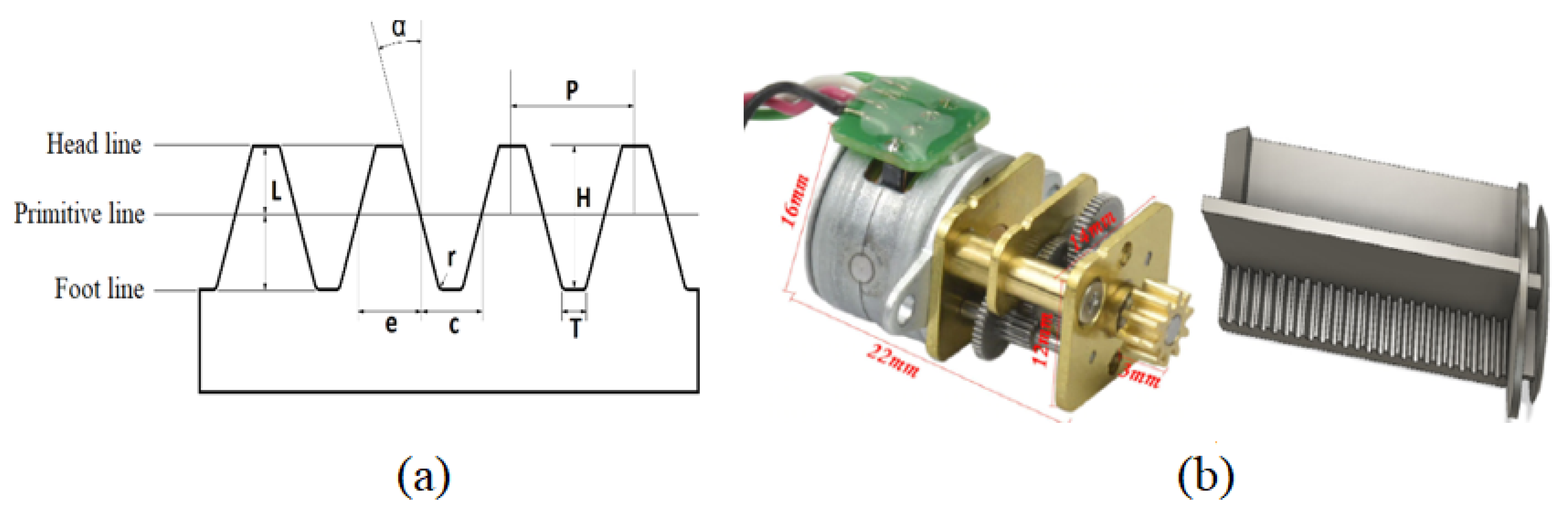
4.1. Engine–Plunger Coupling and Mechanical Design

The selected engine must have enough power to push the viscous tears from the reservoir through the capillary up to the eyes. To accomplish this task, the rubber piston is attached to a computer design toothed plunger shaft with the shape and dimensions indicated in Figure 2a that engages the engine gear, see Figure 2b. The shaft was printed in polylactic acid (PLA) using a 3D printer model Ender-3, it is 5.0 cm long, 17 mm in diameter, and has 25 teeth. When the plunger moves forward, it delivers tears, and the backward movement is used to refill the reservoir. The transmission of the force through the plunger is controlled electronically to supply the exact tear dose in the time and cycles specified by the user. As calculated above, the power needed to overcome viscous forces of highly viscous artificial tears flowing in medical capillaries is ∼3.7 W, (which is shown in Section 6) that the power to overcome the rest of frictional forces is negligible compared with this value, so the ∼14.4 W selected Aiyima 15 stepping engine assures enough power to keep tears injection for extended periods.

4.2. Electronic Design and Assembly

The motor and the microcontroller need 5 V and 3.3 V respectively; the regulators condition the battery voltage at these levels. A driver (L293DD controller) is used to convert the modulated signals from the microcontroller to each phase of the motor. The ESP8266EX microcontroller is used to complete the Wi-Fi connectivity. Due to a reduced number of available pins on the microcontroller, the inverter 74LS14 was used to generate the motor steps sequence using only three pins in the microcontroller. The designed equipment also requires a button to turn the device on and off, as well as two corresponding LEDs to indicate each state. Once all the components are connected in the scheme, track routing was carried out using the EAGLE autorouting tool, and for optimization, the components must be organized so that the routed tracks are the shortest. Figure 3 shows the electronic circuit design, which is modeled by the EAGLE program to obtain the PCB. After printing, the electronic components are welded.
Figure 4 shows the obtained PCB, where only two layers were required (i.e., “Top” and “Bottom”). Some other constraints were included in the routing: the tracks width and length, the distance between components, and drills. The construction and assembly phase begins by welding the components in the following order: welding of tracks, set in place of all the resistors, capacitors, push-buttons, and jumpers, starting with the components of lower height, assembly of integrated circuits, and stepper motor. (cf. Figure 5) shows the finished PCB with components. In the final design, all components were welded on the upper face of the PCB.
The PCB with all the electronic components, the engine, the syringe, and the battery are all assembled within the housing case, shown in a 3D perspective in Figure 6. It was designed with FUSION 360 and CURA, and 3D printed in PLA, it has different compartments with the exact dimensions to firmly place each components. The final weight of the microinjector is 120 g and measures 2.5 × 4.5 × 8.5 cm, an ergonomic size for comfortable manual handling, portability, and storage. The total cost of the elements for its construction is ∼ US $ 150 (See Table S3 for components’ cost in the Supplementary Material).

4.3. Control of the Microinjection System

The microcontroller ESP8266EX is programmed using Arduino’s platform, and crucial parameters like the time between consecutive engine steps, t s t e p , I/O ports, name, password, and IP of the web server, controlling algorithm, etc., are loaded to its memory. t s t e p should be established taking into account not to force the engine beyond its mechanical or physical capabilities, t s t e p = 3.0 × 10 3 s was chosen for the present design.
Algorithm A1 in Appendix A presents the parameters and sequence of logical operation steps of the interface by which the user will enter the parameters’ values to interact with the device. The number of steps is directly related to the requested volume of tears to be injected. The time interval, t i n t e r (in s), indicates the waiting time between consecutive injections. These parameters are initially loaded to operate the microinjector, it remains in standby mode until it receives some external user action. It also can receive instructions to refill or empty the tear reservoir. The setting parameters options is accessible at any time, even though the system is already running. By pressing the start button, the system calculates the total time to inject tears. In this sequence, the system continuously checks whether the number of performed steps is inferior to the maximum, if so it continues injecting, otherwise the system stops, returning to the start state. Additionally, by pressing the finish button, the system finishes executing any pending process and returns to the start state.
The microinjection of tears controlled by the Algorithm A1 follows the continuous pulsed flow pattern shown in Figure 7. The volume of tears to be injected each time is given by the user through the number of steps parameter, n, ( n = 357 steps ≈ One drop ≈ 50 μL), so the microprocessor pushes the plunger during an injection time, t , given by
t = n × t s t e p .
The injection time t is only a fraction of a second, since t s t e p = 3 × 10 3 s. After this, the device remains quiet until the time interval between consecutive injections t i n t e r is reached, at this time the microprocessor injects again. This process repeats periodically until the reservoir is empty or the user changes the variables. The user may change, at any time, n and t i n t e r , to control the amount and frequency of injections of tears according to his/her needs.

5. User Configuration

Figure 8 presents examples of how dry eye patients, either children or adults, may use the tears microinjector. It may be placed inside a waterproof portable case attached to the arm (like the ones for cell phones or ipads) with Velcro tape, the shirt pocket, or any other comfortable option chosen by the user. It is convenient (but not mandatory) to attach the silicon capillary coming from the micro injector to the arm of comfortable or already prescribed glasses. One end of the capillary is connected to the syringe reservoir in the microinjector and the other end must be attached to the patient’s eye commissure, held in place with medical tape. An Android-based cell phone is required to configure the parameters of the device and to control all processes. To start the microinjection of tears, the user must follow the next procedure:
  • Turn on the device by pressing on the start button.
  • To connect his/her Android-based cell phone via Wi-Fi with the ESP8266EX microcontroller web server. The name and password of the network must be previously assigned when programming the microcontroller. Easy to remember names are suggested, like “Dry Eye” for the network’s name.
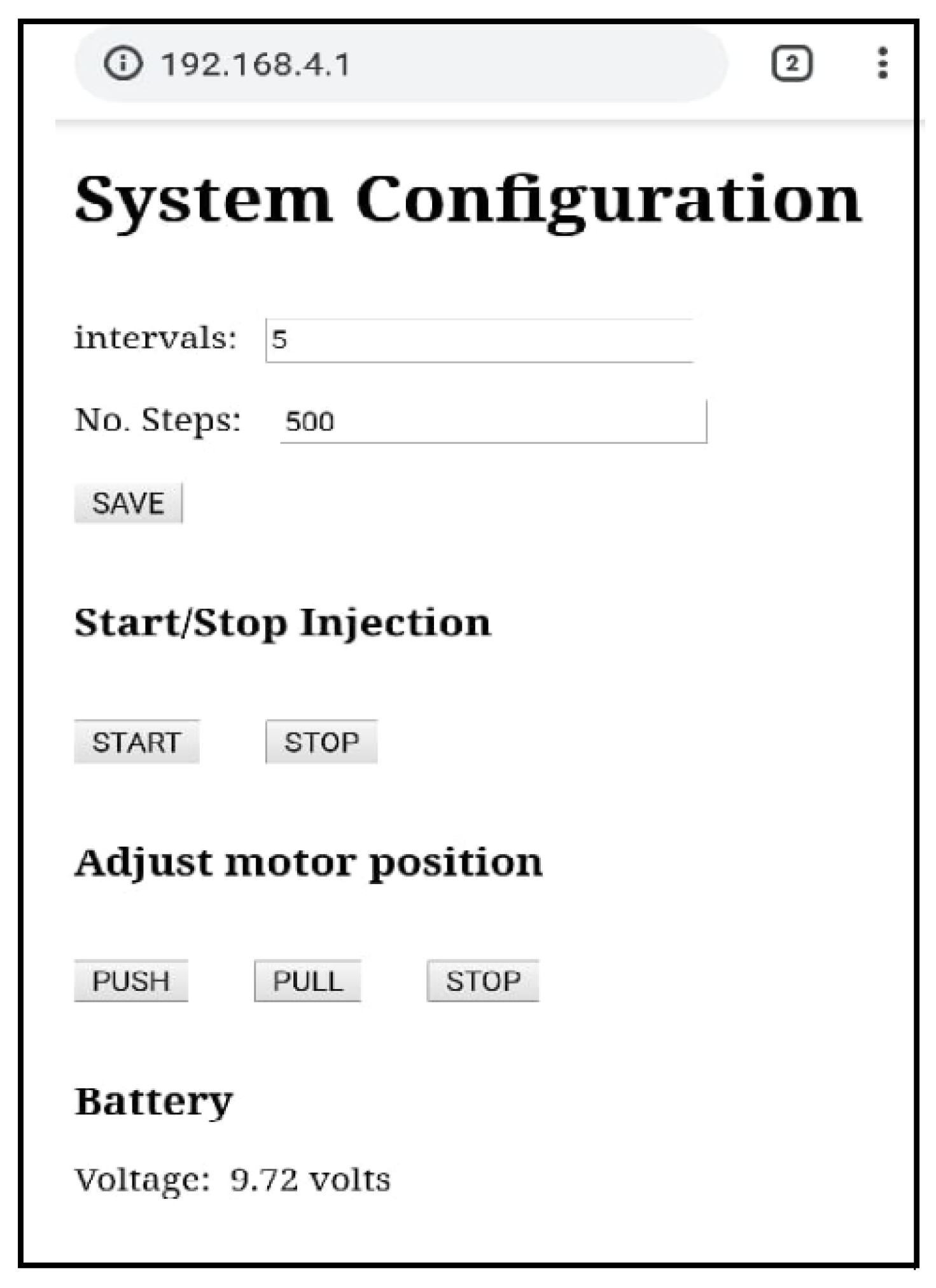
  • Once connected, a web browser opens at the IP address of the server, and the user-friendly interface shown in Figure 9 is displayed. This interface is controlled by the Algorithm A1, it has enter and touch buttons to perform every possible action offered by the microinjector and to introduce input values.
    • Intervals: waiting time between consecutive injections, t i n t e r (number in s).
    • No. Steps: number of steps to be rotated by the engine, n.
    • SAVE: Saves input parameters.
    • START: Starts injection.
    • STOP: Stops/pause injection.
  • Refill/Empty tears reservoir
    • PUSH: Moves the plunger forward at maximum engine power. This option may be used to empty the reservoir.
    • PULL: Moves the plunger backwards at maximum engine power. This option is used to refill the reservoir.
    • STOP: stops movement of the plunger.
  • Battery indicator
    • Voltage: Indicates the current voltage of the battery, this value is updated every 10 s automatically.
Following this intuitive interface, the user controls every variable and request the tears flow he needs at that precise moment. At maximum power the 2.0 mL tears reservoir refills/empty in ∼30 s.

6. Results of Functionality and Performance Tests

A set of experimental test were done prior and after the assembly of the microinjector. The engine power must overcome the theoretically calculated viscous forces plus the power to overcome other friction forces, mainly the one between the rubber piston and the syringe wall. Frictional forces were measured experimentally using the dynamometer PCE-FB 20. Figure 10 shows typical results of the experimental forces observed, and Figure 10a shows the behavior of the friction force between the rubber piston and the wall for an air filled reservoir at 25 °C with an established flow of 13 μL/s in a 1.0 mL syringe (piston displacement of 1.0 cm in 60 s). Due to the friction between the rubber and the plastic wall, the force is not constant, it jumps between 0.0 N up to a slightly variable maximum, | < F M a x > | 1.02 N, in a kind of quasi-periodic behavior, with a general average force of | F a v g | = 0.548 N. The average power applied by the dynamometer is given by
P P i s t o n / W a l l = F a v g · v a v g = 0.09 mW ,
where v a v g is the average piston velocity. Figure 10b shows the behavior of the force when the same syringe is filled with a commercially available formula of artificial tears with a quite low viscosity of 0.05 Pa·s (Lagricel Ofteno). Essentially, the dynamometer force behaves alike, but having higher magnitudes, for this case the average of the maximum peaks is | < F M a x > | 2.98 N and the general average | F a v g | = 1.644 N, which corresponds to a total power P = P P i s t o n / W a l l + P v i s c o c i t y = 0.27 mW. These relatively small values are four orders of magnitude lower that the theoretically calculated power to push highly viscous tears through the capillary (∼3.7 W), so the latter is the one that should be used as the minimum to be delivered by the selected engine. Combining together this experimental procedure to calculate the power needed to overcome friction forces (other than viscosity) with theoretical calculations of viscosity dissipated power assures that the selected engine has enough power to handle artificial tears with the higher reported viscosity, while being small enough to keep the size of the microinjector maneuverable. The selected engine Aiyima 15 delivers ∼14 W, a value reasonably higher than the minimum required, but not much higher to avoid wasting resources.
A set of other verification and validation tests were done to establish the percentage error between the volume of fluid and delivery time programmed by an hypothetical user versus the values actually delivered by the microinjector. These performance tests were done at room conditions using air, distilled water, and commercial artificial tears of viscosity 0.05 Pa·s as testing fluids. Programmed volumes range from 120 to 1000 μL and injection times from 2 to 16.33 h. For these tests, a silicon cylindrical capillary of inner/outer diameter of 600/750 μm and 60 cm long was used. The results are indicated in Table 1, the first and second columns indicate, respectively, the programmed volumes of fluid to be delivered and the time to do so. The first result is in the third column “Obtained volume”, within experimental error (1 μL), the microinjector delivered, for the three fluids, the programmed volume without any problem. Regarding the time, the fourth and fifth columns globally titled as “Air”, indicate, respectively, the time taken to the microinjector to deliver the programmed volume and the percentage error. Once again, within experimental error (1.0 s), there is no perceptible delay. For the case of distilled water, the sixth column indicates that a measurable delay is now present. The top row indicates, for example, that 1.0 mL was programmed to be delivered in 16 h with 20 min, however the microinjector took 1 min 3 s longer, the time error being around 0.11%. As the viscosity increases the time delay is longer, as the last two columns for artificial tears show. For this case it took 1 min 30 s longer than the time programmed to inject 1.0 mL. These kinds of experiments were repeated with all artificial tears available in Mexican drug stores, for the most viscous, μ = 80 Pa·s, the time error was 2.2%. For practical purposes, this time error represents no major problem, since the user may easily get the flow he/she needs by proportionally decreasing the value of t i n t e r . In general terms, the microinjector will deliver without any problem any requested flow within normal ranges of lubrication.
There are at least two parameters that the user must specify to obtain a desired dose of tears according to his/her needs, the most natural may be to specify a volume of tears and the time to be injected, let us say for example 1.0 mL in 5 h, while another way may be to specify 1 drop (∼50 μL) every 15 s. Ultimately, the user is specifying the average flow of tears he/she needs to feel better. From that flow, the number of steps the engine must rotate and the time to do so must be determined. The volume of tears injected by each engine step depends on the mechanical design of the toothed plunger, gears coupling, and syringe diameter, in any design it should be corroborated experimentally. For the present case, the injection of 1.0 mL takes the microinjector 7500 steps (0.133 μL/step). Taking as a common approach the practical medical equivalence of 20 drops equivalent to 1.0 mL, then it is necessary to rotate the engine ∼375 steps to have 1 drop of tears. For example, if the user needs half a drop every 15 s, he/she needs to enter into the Android interactive display n = 188 and t i n t e r = 15 s. The engine will take 0.56 s to inject the fluid. This operation will be repeated periodically every 15 s until the user stops the device. In case the user needs a larger volume of fluid he/she can double or triple the dose whenever he/she needs by increasing or decreasing the number of steps. Equivalently, the user may choose to increase or decrease the time interval between injections, it can be done anytime. The minimum possible volume of tears to inject is the equivalent to 1 engine step (=0.133 μL), the maximum is the total volume of the syringe (2.0 mL).
For the mechanical design of the present microinjector, the relationship between the flow Q, t i n t e r , and n is given by
Q = 0.1333 t n μ L s = 2.2 × 10 3 t n μ L min .
Even though the relationship given by Equation (6) can easily be established once the total number of steps needed to empty the total syringe volume is known, it is through experimental tests that this parameter should be firmly established. Figure 11 shows the results of two of these performance tests, both done at t i n t e r = 15.0 s and n = 15 and 30 respectively, using 1.0 mL of Lagricel Ofteno as testing tears. Once the microinjector started running, the injected volume and the elapsed time were recorded and plotted. The figure shows a well defined linear behavior, where square and circle dots represent experimental data, while the solid line represents a linear fit. Since a linear behavior was expected, the deviation between the experimental data and the linear fit may be taken as a quantitative parameter to measure the stability of the microinjector, where the lower the deviation, the higher the stability. For both cases, the graphs show a significantly high stability of the microinjector along all hours of operation. If we divide the total time taken for each experiment to supply the whole 1.0 mL, t T o t a l , by t i n t e r (15 s) and multiply by n then we get the total number of steps needed to supply the 1.0 mL of tears, n T o t a l = 7500 ± 8 steps.
Therefore, this method of continuous pulsated injection of artificial tears is proposed for people who have dry eye disease and have an Android device capable of connecting to the Wi-Fi network to automatically and continuously inject medical lubricant drops into the eyes. This method does not require special effort from the patients and guarantees its effectiveness in the treatment, the selection of the right flow avoids flooding the eyes and wetting eyelids. The patient may choose from the plethora of available artificial tears formula. As the drop hits the eyeball, instinctive blinking will help spread the artificial tear over the eye. As there is no direct contact between the device and the eyes, the problems of ocular irritation and contamination of the medication are avoided. The reservoir maintains the fluid at room temperature and is separated from the driving mechanism. The design is non-invasive and comfortable compared to the traumatic external pumps using a tube installed subcutaneously to reach the lateral conjunctival sac.
As previously mentioned, the majority of patients with dry eyes belong to the elderly population, thus, a portable, automatic, and practical microinjection device like the one presented here may palliate the patient’s physical constraints. The artificial tear microinjection system presented here can have many other considerable advantages in patients with motor problems, the disabled, the elderly, and children. It reduces medical costs and increases patient comfort.
A monitored medical study with 30 patients with dry eye syndrome is currently under way. The patients will use the artificial tears microinjection system for three continuous months, regulating the flow according to their needs and another three months attending to the problem by manual drip. The results in which patients establish the difference in their well-being by comparing both methods will be published shortly. Murubeet al. [26] conducted clinical studies on six severe dry eye patients to whom they apply continuously artificial tears to the eye surface using a catheter implanted subcutaneously and conclude that the ocular surface of all patients improved compared with the manual topical application of drops. Rubenet al. [41] also conducted pioneer studies of continuous application of artificial tears, concluding that this method alleviates symptoms in severe dry eye conditions not alleviated by other methods. These previous reports demonstrate the advantages of the continuous injection and viability of clinical applications of the present microinjector.

7. Conclusions

An electronic, automated microinjector for the controlled dosage of artificial tears was designed, manufactured, and tested. The selection of the electronic components took into account the range of viscosities of artificial tears and the natural range of the eyes’ lubricants’ flow. The user controls in real time and via Wi-Fi all the functions of the injector using a user-friendly interface programmed for Android devices, mainly the volume of tears to be dosed, and the time interval between injections. The method is suitable and promising to deliver artificial tears mainly for patients with severe dry eye syndrome, patients suffering mobility problems, the elderly, children, hospitalized patients, and whoever needs a continuous and efficient long-term treatment. For patients who typically request assistance, the costs of hospital care can be reduced. It can also be used by any dry eye patient who wishes to improve the dosage regularity and accuracy of artificial tears in an automated and simple way. The method is not invasive and does not require any mechanical action by the patient.

Supplementary Materials

The following are available at https://0-www-mdpi-com.brum.beds.ac.uk/2076-3417/10/5/1883/s1, Table S1: Specifications of the microcontroller ESP8266EX with ESP-12 Wi-Fi module, Table S2: Specifications of voltage regulators produced by Advanced Monolithic Systems, Table S3: Total cost of the microinjector.

Author Contributions

Conceptualization, N.M.-B. and G.V.-G.; data curation, I.L.-R.; formal analysis N.M.-B., L.A.I.-B., I.L.-R., and G.V.-G.; funding acquisition, G.V.-G.; investigation, N.M.-B., L.A.I.-B., and G.V.-G.; methodology, I.L.-R., G.V.-G., N.M.-B., and L.A.I.-B.; resources, G.V.-G. and I.L.-R.; software N.M.-B. and I.L.-R.; validation, N.M.-B. and G.V.-G.; visualization, N.M.-B. and G.V.-G.; writing—original draft preparation, N.M.-B. and G.V.-G.; writing—review and editing G.V.-G.; project administration, G.V.-G.; supervision, G.V.-G. All authors have read and agreed to the published version of the manuscript.

Funding

This research was funded by the Mexican National Council for Science and Technology (CONACYT) through the Basic Science Project 2014 # 223500 and a Ph.D scholarship of NMB # 572895 and by the Coordination for Scientific Research of the Universidad Michoacana de San Nicolás de Hidalgo, Basic Science Projects 2018, 2019 and 2020.

Acknowledgments

The authors would like to thank the Microelectronics Laboratory of the National Institute of Astrophysics, Optics, and Electronics, INAOE in Puebla, Mexico for receiving NMB for a research stay.

Conflicts of Interest

The authors declare no conflict of interest.

Appendix A

Algorithm A1 Microinjector sequence control.
1: Start
2: Read_EEPROM(No_Steps, Time_interval
3: Initialize_Variables (No_Steps, Time_interval)
4: Start_Server()
5: Set_Ports_I/O()
6: Continuous_Cycle()
7: if Web_Client_Request then
8:  if Save_Button then
9:   Read_Web_Page (No_Steps, Time_interval)
10:   Save_in_EEPROM (No_Steps, Time_interval )
11:   Initialize_Variables (No_Steps, Time_interval )
12:  if Pull_Button then
13:   Rotate_Motor_Right ()
14:  if push_Button then
15:   Rotate_Motor_Left ()
16:  if Stop_Button then
17:   stop_Motor()
18:  if Start_Button then
19:   Flag_Active_Start
20:  if Finish_Button then
21:   Flag_Inactive_Start
22:  if Active_Time > 10 Seconds then
23:   Update_Battery_voltage()
24: if Flag_Active_Start then
25:  if Interval >= Elapsed_time then
26:   Move_Motor (Number_Steps)
27:   Save_Data_in_EEPROM (Number_Steps)
28:  if Number_Steps >= Steps_MAX then
29:   Flag_Inactive_Start
30: if Flag_Inactive_Start then
31:  Stop_Motor;
32:  Save_Steps_in_EEPROM;
33: Finish

References

  1. Barabino, S.; Labetoulle, M.; Rolando, M.; Messmer, E.M. Understanding symptoms and quality of life in patients with dry eye syndrome. Ocul. Surf. 2016, 14, 365–376. [Google Scholar] [CrossRef] [PubMed]
  2. Zheng, Y.; Wu, X.; Lin, X.; Lin, H. The prevalence of depression and depressive symptoms among eye disease patients: A systematic review and meta-analysis. Sci. Rep. 2017, 7, 46453. [Google Scholar] [CrossRef] [PubMed] [Green Version]
  3. Onwubiko, S.N.; Eze, B.I.; Udeh, N.N.; Arinze, O.C.; Onwasigwe, E.N.; Umeh, R.E. Dry eye disease: Prevalence, distribution and determinants in a hospital-based population. Contact Lens Anterior Eye 2014, 37, 157–161. [Google Scholar] [CrossRef] [PubMed]
  4. Clegg, J.P.; Guest, J.F.; Lehman, A.; Smith, A.F. The annual cost of dry eye syndrome in France, Germany, Italy, Spain, Sweden and the United Kingdom among patients managed by ophthalmologists. Ophthalmic Epidemiol. 2006, 13, 263–274. [Google Scholar] [CrossRef] [PubMed]
  5. Schaumberg, D.A.; Sullivan, D.A.; Buring, J.E.; Dana, M.R. Prevalence of dry eye syndrome among US women. Am. J. Ophthalmol. 2003, 136, 318–326. [Google Scholar] [CrossRef]
  6. Schaumberg, D.A.; Dana, R.; Buring, J.E.; Sullivan, D.A. Prevalence of dry eye disease among US men: Estimates from the Physicians’ Health Studies. Arch. Ophthalmol. 2009, 127, 763–768. [Google Scholar] [CrossRef] [Green Version]
  7. Osae, A.; Gehlsen, U.; Horstmann, J.; Siebelmann, S.; Stern, M.; Kumah, D.; Steven, P. Epidemiology of dry eye disease in Africa: The sparse information, gaps and opportunities. Ocul. Surf. 2017, 15, 159–168. [Google Scholar] [CrossRef]
  8. Song, P.; Xia, W.; Wang, M.; Chang, X.; Wang, J.; Jin, S.; Wang, J.; Wei, W.; Rudan, I. Variations of dry eye disease prevalence by age, sex and geographic characteristics in China: A systematic review and meta-analysis. J. Glob. Health 2018, 8, 020503. [Google Scholar] [CrossRef]
  9. Donthineni, P.R.; Kammari, P.; Shanbhag, S.S.; Singh, V.; Das, A.V.; Basu, S. Incidence, demographics, types and risk factors of dry eye disease in India: Electronic medical records driven big data analytics report I. Ocul. Surf. 2019, 17, 250–256. [Google Scholar] [CrossRef]
  10. Andrade, F.N.V.; Flores, T.E.M.; Barzola, C.V.R.; Mestanza, P.M.G. Sindrome de ojo seco asociado al computador, manifestaciones clínicas y factores de riesgo. Sinerg. Educ. 2020, E, 1–9. [Google Scholar]
  11. Doughty, M.J.; Fonn, D.; Richter, D.; Simpson, T.; Caffery, B.; Gordon, K. A patient questionnaire approach to estimating the prevalence of dry eye symptoms in patients presenting to optometric practices across Canada. Optom. Vis. Sci. Off. Publ. Am. Acad. Optom. 1997, 74, 624–631. [Google Scholar] [CrossRef] [PubMed]
  12. Shimmura, S.; Shimazaki, J.; Tsubota, K. Results of a population-based questionnaire on the symptoms and lifestyles associated with dry eye. Cornea 1999, 18, 408–411. [Google Scholar] [CrossRef] [PubMed]
  13. Yazdani, C.; McLaughlin, T.; Smeeding, J.E.; Walt, J. Prevalence of treated dry eye disease in a managed care population. Clin. Ther. 2001, 23, 1672–1682. [Google Scholar] [CrossRef]
  14. Stapleton, F.; Alves, M.; Bunya, V.Y.; Jalbert, I.; Lekhanont, K.; Malet, F.; Na, K.S.; Schaumberg, D.; Uchino, M.; Vehof, J.; et al. Tfos dews ii epidemiology report. Ocul. Surf. 2017, 15, 334–365. [Google Scholar] [CrossRef] [PubMed]
  15. O’Neil, E.C.; Henderson, M.; Massaro-Giordano, M.; Bunya, V.Y. Advances in dry eye disease treatment. Curr. Opin. Ophthalmol. 2019, 30, 166–178. [Google Scholar] [CrossRef]
  16. Fezza, J.P. Cross-linked hyaluronic acid gel occlusive device for the treatment of dry eye syndrome. Clin. Ophthalmol. 2018, 12, 2277. [Google Scholar] [CrossRef] [Green Version]
  17. Barta, Z.; Czompa, L.; Rentka, A.; Zold, E.; Remenyik, J.; Biro, A.; Gesztelyi, R.; Zsuga, J.; Szodoray, P.; Kemeny-Beke, A. Evaluation of Objective Signs and Subjective Symptoms of Dry Eye Disease in Patients with Inflammatory Bowel Disease. BioMed Res. Int. 2019, 2019, 8310583. [Google Scholar] [CrossRef] [Green Version]
  18. German, E.J.; Hurst, M.A.; Wood, D. Reliability of drop size from multi-dose eye drop bottles: Is it cause for concern? Eye 1999, 13, 93. [Google Scholar] [CrossRef] [Green Version]
  19. Surya, V.; Srutartha, B.; Shreya Kulkarni, K.D. Ocular Drug Delivery System Using Open-Source Syringe Pump. Asian J. Pharm. Clin. Res. 2018, 11, 152–157. [Google Scholar]
  20. Mishima, S.; Gasset, A.; Klyce, S.; Baum, J. Determination of tear volume and tear flow. Investig. Ophthalmol. Vis. Sci. 1966, 5, 264–276. [Google Scholar]
  21. Cerretani, C.F.; Radke, C. Tear dynamics in healthy and dry eyes. Curr. Eye Res. 2014, 39, 580–595. [Google Scholar] [CrossRef] [PubMed]
  22. Li, S.; Kim, Y.H.; Li, W.; Lin, M.C.; Radke, C.J. Human lacrimal production rates from modified Schirmer-tear test. Optom. Vis. Sci. 2018, 95, 343–348. [Google Scholar] [CrossRef] [PubMed] [Green Version]
  23. Ousler, G.W., III; Hagberg, K.W.; Schindelar, M.; Welch, D.; Abelson, M.B. The ocular protection index. Cornea 2008, 27, 509–513. [Google Scholar] [CrossRef] [PubMed]
  24. Jones, L.T. Anatomy of the tear system. Int. Ophthalmol. Clin. 1973, 13, 3–22. [Google Scholar] [CrossRef] [PubMed]
  25. Chan, T.C.; Chow, S.S.; Wan, K.H.; Yuen, H.K. Update on the association between dry eye disease and meibomian gland dysfunction. Hong Kong Med. J. 2019, 25, 38–47. [Google Scholar] [CrossRef] [Green Version]
  26. Murube, J.; Murube, E.; ChenZhuo, L.; Rivas, L. Subcutaneous abdominal artificial tears pump-reservoir for severe dry eye. Orbit 2003, 22, 29–40. [Google Scholar] [CrossRef]
  27. Pillay, V.; Choonara, Y.E.; du Toit, L.C. Intraocular drug delivery technologies: Advancing treatment of posterior segment disorders of the eye. In Nano-Biomaterials for Ophthalmic Drug Delivery; Springer: Berlin, Germany, 2016; pp. 407–460. [Google Scholar]
  28. Tiffany, J.M. The viscosity of human tears. Int. Ophthalmol. 1991, 15, 371–376. [Google Scholar] [CrossRef]
  29. Andres, S.; Garcia, M.; Espina, M.; Valero, J.; Valls, O. Tear pH, air pollution, and contact lenses. Am. J. Optom. Physiol. Opt. 1988, 65, 627–631. [Google Scholar] [CrossRef]
  30. Tiffany, J.M. Composition and biophysical properties of the tear film: Knowledge and uncertainty. In Lacrimal Gland, Tear Film, and Dry Eye Syndromes; Springer: Berlin, Germany, 1994; pp. 231–238. [Google Scholar]
  31. Versura, P.; Profazio, V.; Campos, E. Performance of tear osmolarity compared to previous diagnostic tests for dry eye diseases. Curr. Eye Res. 2010, 35, 553–564. [Google Scholar] [CrossRef]
  32. Bhojwani, R.; Cellesi, F.; Maino, A.; Jalil, A.; Haider, D.; Noble, B. Treatment of dry eye: An analysis of the British Sjögren’s Syndrome Association comparing substitute tear viscosity and subjective efficacy. Contact Lens Anterior Eye 2011, 34, 269–273. [Google Scholar] [CrossRef]
  33. Kirby, B.J. Micro-And Nanoscale Fluid Mechanics: Transport in Microfluidic Devices; Cambridge University Press: Cambridge, UK, 2010. [Google Scholar]
  34. Pisano, A. From Tubes and Catheters to the Basis of Hemodynamics: The Hagen–Poiseuille Equation. In Physics for Anesthesiologists; Springer: Berlin, Germany, 2017; pp. 55–61. [Google Scholar]
  35. Lievens, C.; Berdy, G.; Douglass, D.; Montaquila, S.; Lin, H.; Simmons, P.; Carlisle-Wilcox, C.; Vehige, J.; Haque, S. Evaluation of an enhanced viscosity artificial tear for moderate to severe dry eye disease: A multicenter, double-masked, randomized 30-day study. Contact Lens Anterior Eye 2019, 42, 443–449. [Google Scholar] [CrossRef] [PubMed] [Green Version]
  36. Milner, M.S.; Beckman, K.A.; Luchs, J.I.; Allen, Q.B.; Awdeh, R.M.; Berdahl, J.; Boland, T.S.; Buznego, C.; Gira, J.P.; Goldberg, D.F.; et al. Dysfunctional tear syndrome: Dry eye disease and associated tear film disorders–new strategies for diagnosis and treatment. Curr. Opin. Ophthalmol. 2017, 28, 3. [Google Scholar] [CrossRef] [PubMed] [Green Version]
  37. Sianoudis, I.; Drakaki, E. An approach to Poiseuille’s law in an undergraduate laboratory experiment. Eur. J. Phys. 2008, 29, 489. [Google Scholar] [CrossRef]
  38. Poiseuille, J. Recherches expérimentales sur le mouvement des liquides dans les tubes de très petits diamètres [Experimental research on the movement of liquids in capillary of very small diameters]. Comptes Rendus Hebdomadaires Des SÉances de L’Académie des Sciences 1840, 11, 1041–1048. [Google Scholar]
  39. Hagen, G. Ueber die Bewegung des Wassers in engen cylindrischen Röhren. Ann. Phys. 1839, 122, 423–442. [Google Scholar] [CrossRef] [Green Version]
  40. Entwicklungsmethodik für Mechatronische Systeme. Design Methodology for Mechatronic Systems: VDI 2206, VDI-Richtlinien; Beuth Verlag GmbH: Berlin, Germany, 2004; Volume 2206. [Google Scholar]
  41. Ruben, M.O.; Trodd, C.H. Constant perfusion for dry eyes and sockets. Br. J. Ophthalmol. 1978, 62, 268–270. [Google Scholar] [CrossRef] [Green Version]
Figure 1. Electrical and electronics components. (a) Microcontroller ESP8266EX with ESP-12 Wi-Fi Module; (b) Integrated circuits Hex Inverter 74HC04D; (c) Voltage Regulator KIA1117-3.3; (d) Voltage Regulator AMS1117-5.0; (e) Integrated circuit L293DD; (f) Aiyima 15 Stepping Micro Gear Motor; (g) switch button.
Applsci 10 01883 g001
Figure 2. (a) Scheme of the toothed plunger shaft, P = 1.57 mm; H = 1.08 mm; e = 0.78 mm; c = 0.78 mm; L = 0.5 mm; α = 20 °; r = 0.15 mm; T = 0.42 mm. (b) Engine showing its toothed circular gear and 3D printed toothed shaft.
Applsci 10 01883 g002
Figure 3. Electronic circuit design using EAGLE: (a) microcontroller, position sensor, programming connector, and reset buttons; (b) control of pins number; (c) power stages and motor connector; (d) power source with regulators (5 V and 3.3 V).
Applsci 10 01883 g003
Figure 4. Printed circuit board of the microinjector. Left: Board top. Right: Board bottom.
Applsci 10 01883 g004
Figure 5. Finished printed circuit board (PCB) with components.
Applsci 10 01883 g005
Figure 6. Microinjector with its components placed in their respective compartments.
Applsci 10 01883 g006
Figure 7. Continuous pulsed flow of the microinjector. t i n t e r indicates the time interval (in s) between consecutive injections, t is the active injection time where the microprocessor pushes the plunger.
Applsci 10 01883 g007
Figure 8. Elderly (a) and children (c) controlling and using the tears microinjector (b).
Applsci 10 01883 g008
Figure 9. Android-based user-friendly interface to control the microinjector.
Applsci 10 01883 g009
Figure 10. Experimental pushing force of the syringe using a BD Plastipak Brand syringe. (a) Force measured with air. (b) Force measured with a commercial ophthalmic solution of 0.054 Pa·s of viscosity.
Applsci 10 01883 g010
Figure 11. Injection time behavior of the microinjection system versus volume.
Applsci 10 01883 g011
Table 1. Microinjection system performance tests with air, distilled water, and Lagricel Ofteno.
Programmed Volume (μL)Programmed Time (h-m-s)Obtained Volume (μL)AirDistilled WaterLagricel Ofteno (Ophthalmic Solution 0.4%)
Real Time (h-m-s)Time Error (%)Real Time (h-m-s)Time Error (%)Real Time (h-m-s)Time Error (%)
100016-20-00100016-20-000.00016-21-030.10016-21-300.153
96016-00-0096016-00-000.00016-00-430.07016-01-310.157
78013-00-0078013-00-000.00013-00-370.07013-01-160.162
60010-00-0060010-00-000.00010-00-290.08010-01-070.186
36006-00-0036006-00-010.00406-00-320.14006-00-510.236
12002-00-0012002-00-040.05502-00-070.09002-00-180.249

