Ultrawideband Low-Profile and Miniaturized Spoof Plasmonic Vivaldi Antenna for Base Station


1
Key Laboratory of Specialty Fiber Optics and Optical Access Networks, Shanghai University, Shanghai 200444, China
2
Shanghai Institute of Microsystem and Information Technology, Chinese Academy of Sciences, Shanghai 200050, China
*
Author to whom correspondence should be addressed.
Appl. Sci. 2020, 10(7), 2429; https://0-doi-org.brum.beds.ac.uk/10.3390/app10072429
Submission received: 23 February 2020
/
Revised: 30 March 2020
/
Accepted: 31 March 2020
/
Published: 2 April 2020
(This article belongs to the Special Issue Passive Planar Microwave Devices )
Abstract
:Stable radiation pattern, high gain, and miniaturization are necessary for the ultra-wideband antennas in the 2G/3G/4G/5G base station applications. Here, an ultrawideband and miniaturized spoof plasmonic antipodal Vivaldi antenna (AVA) is proposed, which is composed of the AVA and the loaded periodic grooves. The designed operating frequency band is from 1.8 GHz to 6 GHz, and the average gain is 7.24 dBi. Furthermore, the measured results show that the radiation patterns of the plasmonic AVA are stable. The measured results are in good agreement with the simulation results.
1. Introduction
The fifth-generation (5G) mobile communication systems have found various applications, such as autonomous driving [1], telemedicine [2], and virtual reality [3]. Considering radio wave propagation and available bandwidth, the bands between 3 and 5 GHz have been allocated for 5G services in many regions, such as 3.4–3.8 GHz in Europe, 3.7–4.2 GHz in the USA, and 3.3–3.6 and 4.8–4.99 GHz in China [4]. Hence, in the 2G/3G/4G/5G base station applications, the wide bandwidth covers the 2G, 3G, and 4G bands (1.7–2.7 GHz) and the new sub-6 GHz 5G frequency bands. It is urgent to investigate and design ultra-wideband antennas to cover the aforementioned bands and maintain good impedance matching within the entire frequency bands of interest, with a stable half-power bandwidth (HPBW) and a smaller structure.
Crossed dipole antennas are widely used in wireless communication systems due to their advantages of wide bandwidth, stable radiation patterns, and ease of fabrication [5]. Various crossed dipoles were utilized to achieve a wide impedance bandwidth, such as magnetoelectric dipole antennas [6], bow-tie dipole [7], fan-shaped dipole [8], octagonal loop dipole [9], and double-loop dipole [10]. For most of them, the wide impedance bandwidth only covers 2G/3G/4G bands. Furthermore, the antenna profile is not low due to the necessary broadband feeding part.
The microstrip antennas have advantages of low profile, light weight, and ease of conformability. However, their impedance bandwidth and isolation are not good enough. Some attractive techniques have been proposed to broaden the impedance bandwidth by using parasitic patches [11], loading H-slot [12] and U-slot [13], using a multiresonant structure [14], and using a fractal structure [15]. Although the shorted-dipoles printed antenna fed by integrated baluns [16] and the dual-band folded dipole antenna [17] cover 2G/3G/4G/5G frequency band, the gain and radiation pattern of these antennas are unstable over the operating frequency band.
Another typical ultra-wideband antenna is based on tapered slot technique. As one of the most typical types, Vivaldi antenna was firstly introduced in [18] and has found many applications [19,20]. However, its size is still large. Surface plasmons (SPs) are collective electron–photon oscillations confined to the metal surface, which are characterized by subwavelength confinement and field enhancement in optical spectrum [21]. Spoof SPs could be obtained by constructing periodic metal surfaces to get the characteristics of SPs in the microwave frequencies [22,23]. They have been explored in many antenna applications such as holo-graphic antenna [24,25], metasurface planar lenses [26,27], and metasurface superstrate [28,29]. It has been shown that by loading plasmonic metamaterials, the antenna can be efficiently miniaturized [30].
Here, by loading plasmonic metamaterials, a modified antipodal Vivaldi antenna (AVA) is designed and measured, which is composed of the AVA and the loaded periodic slots. The designed operating frequency is from 1.8 GHz to 6 GHz, which covers 2G/3G/4G/5G frequency band. The simulated results and measured results agree well. It shows that the radiation pattern of the plasmonic AVA is stable and the average gain is 7.24 dBi over the operating frequency band.
2. Methods and Principles
The typical monopole antenna and the plasmonic monopole antenna are illustrated in Figure 1a. Usually, the plasmonic monopole antenna is composed of the corrugated monopole antenna with grooves along the metal wire. Here, we use meander wires to simulate the effects of the grooves for simplicity. The dispersion relations of both antennas are calculated and plotted in Figure 1b. When the groove depth b is 0 mm, it is the typical monopole antenna. From Figure 1b, it can be seen that when the groove depth is increased (from 0 mm to 3.6 mm), the corresponding asymptotic frequencies are decreased and the dispersion curves are lowered. It can be concluded that when the wave vector β is fixed, the operating frequency is lower for the plasmonic monopole antenna with deeper grooves. Hence, the electrical size of the plasmonic monopole antenna would be smaller, compared with that of the traditional monopole antenna.
The efficiencies of the typical and plasmonic monopole antennas are calculated and illustrated in Figure 2. Figure 2b shows the efficiencies of the plasmonic monopole antenna with different groove depths from 1 mm to 4 mm. From Figure 2b, it can be seen that the operating frequencies red-shifts (corresponding to longer wavelengths) when the groove depth is increased for the fixed height of the monopole antenna (25 mm). Especially, the efficiency curves corresponding to three typical groove depths are plotted in Figure 2c. It can be clearly observed that the central operating frequency red-shifts when the groove depth b is 0 mm (typical monopole antenna), 1.4 mm, and 3.6 mm, respectively. Meanwhile, we can observe that there is an optimized efficiency when tuning the groove depth. Hence, it indicates that the plasmonic theory provides a scheme for miniaturization and optimization of the antenna.
3. Design of Plasmonic Antipodal Vivaldi Antenna
The typical AVA is illustrated in Figure 3a, which is denoted by Structure A, where the metal layers are on both sides of the 0.8-mm-thickness F4B substrate () with a dimension of 94 mm × 70 mm. A microstrip feeding line is adopted for broadband impendence matching. The port width of the microstrip feeding line is fixed to 1.35 mm. The exponential profile curves employed in this design can be calculated by the following equations:
The tentative plasmonic AVA is shown in Figure 3b, which is named as Structure B. The final plasmonic AVA is shown in Figure 3c, which is denoted by Structure C, where periodic elliptic grooves are cut from the feeding section to the terminal of the antenna for both structures. Furthermore, the rectangular gradual grooves with a width of 1 mm around the feeding section are further etched to realize the miniaturization of the AVA for Structure C. The detailed structures of the gradual grooves are shown in the insets of Figure 3b,c.
The numerical simulations were performed by using CST Microwave Studio. The simulated return losses changing with the grooves are shown in Figure 4. First, from Figure 4a, it can be observed that the impedance matching at lower frequencies is better for Structure C, compared with Structure B, and the operating frequency red-shifts. Thus, loading the rectangular gradual grooves can make the AVA further miniaturized. Then, the typical parameters of structures B and C are the maximum groove depth l1 and the groove gap d2. It can be seen that the operating frequency red-shifts when the maximum groove depth l1 is bigger, while the groove gap d2 mainly affects the input impedance at higher frequency. The optimized maximum groove depth l1 and the groove gap d2 are set to be 26 mm and 1.25 mm, respectively, to make sure that the lowest operating frequency is 1.8 GHz when the S11 is not larger than −10 dB.
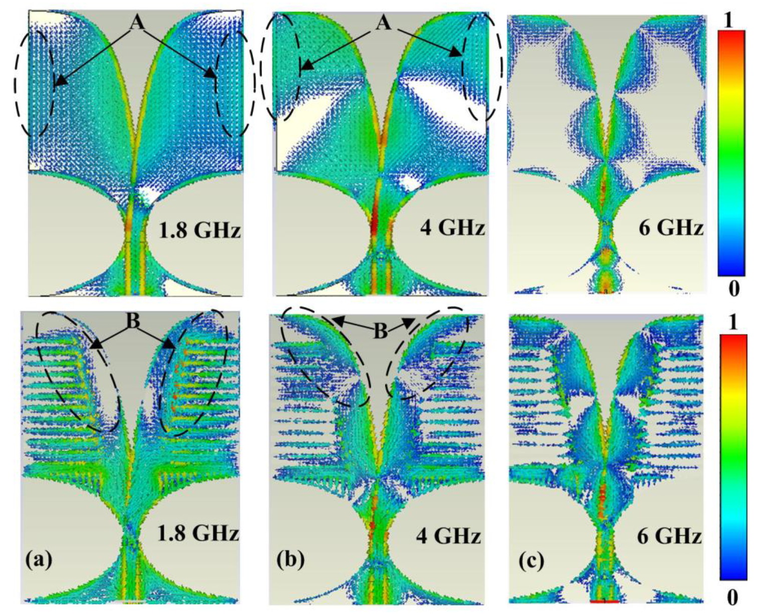
It is expected that the etched grooves would change the surface currents and then the effective impedance. In order to understand the operating principle of the AVA and plasmonic AVA, surface current distributions at 1.8 GHz, 4 GHz, and 6 GHz are illustrated in Figure 5. First, it can be seen that the surface currents distribution at the region A of the AVA is larger than that of the plasmonic AVA at 1.8 GHz. After loading the periodic slots, electromagnetic waves are concentrated at the end of the coupling section and the inner end of the tapered slots (region B), as shown in Figure 5a. Hence, radiated electromagnetic energy can be concentrated in the axial direction of the tapered slot (y-direction). The same thing is true for the cases of the plasmonic AVA at 4 GHz and 6 GHz, as shown in Figure 5b,c.
4. Results
In order to validate the proposed antenna, the plasmonic AVA has been fabricated and tested. A 50-Ω SMA connector was used to feed the antenna. The fabricated plasmonic AVA is shown in Figure 6a,b. The antennas were measured by using vector network analyzer (Keysight 8722ES), and the anechoic chamber operates from 600 MHz to 40 GHz.
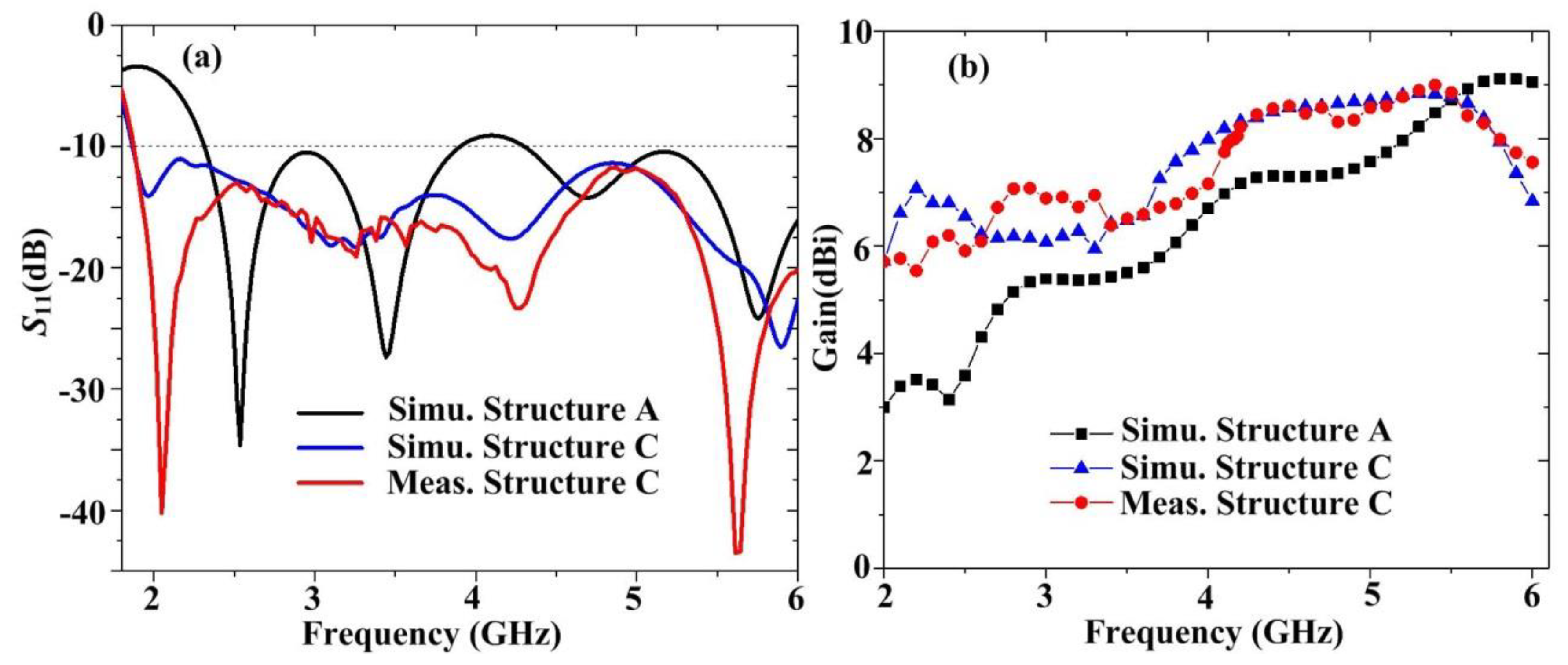
The simulated and measured reflection coefficients are illustrated in Figure 7a. It can be observed that the lowest operating frequency (S11 ≤ −10 dB) of Structure A (typical AVA) is 2.4 GHz, while it is 1.8 GHz for Structure C (plasmonic AVA). The corresponding electrical sizes are 0.75λ0 and 0.56λ0, respectively, where λ0 is the wavelength in the air corresponding to the lowest operating frequency. Hence, it can be seen that the electrical size of the plasmonic AVA has been reduced by 25.3 percent, compared with that of the typical AVA. The measured S11 of the plasmonic AVA is also plotted in Figure 7a. It can be observed that the measured results agree well with the simulation results. The simulated and measured gains of the AVA and the plasmonic AVA are shown in Figure 7b. Compared to the gains of the AVA, it can be seen that the gain of the plasmonic AVA has been increased at the frequencies lower than 5.5 GHz and decreased at frequencies higher than 5.5 GHz. The measurement results agree well with the simulated results for the plasmonic AVA. The gain is larger than 5.5 dBi over the operating frequency from 1.8 GHz to 6 GHz. The measured peak gain is 9.12 dBi at 5.4 GHz. The measured average gain is 7.24 dBi over the operating frequency band, which covers 2G/3G/4G/5G bands.
The simulated and measured radiation patterns of the plasmonic AVA at 1.8 GHz, 4 GHz, and 6 GHz are illustrated in Figure 8. The upper and lower panels are the E-plane and H-plane radiation patterns, respectively. The half-power beam width (HPBW) in E-plane of the AVA and plasmonic AVA is shown in the Table 1. It can be seen that the radiation patterns of the plasmonic AVA are stable, compared with the results of the typical AVA.
5. Discussion
The quantitive comparison of similar antennas has been given in Table 2. For the 2G/3G/4G/5G base station applications, the wide bandwidth is necessary to cover the 2G, 3G, and 4G bands and the new sub-6 GHz 5G frequency bands. Hence, only sub-6 GHz frequency band of the proposed antenna is shown here. Besides, the gain, HPBW, and the electrical size should be considered simultaneously for the base station antenna. From Table 2, we can see that the lowest operating frequency of the proposed plasmonic AVA is the lowest (1.8 GHz). The electrical size is 0.56λ0, which is a little larger than that of Refs. [31,32,33], where λ0 is the wavelength in the air corresponding to the lowest operating frequency. The minimum gain (5.5 dBi) is the highest, since high gain is necessary for the base station antenna.
6. Conclusions
Here, a broadband and miniaturized plasmonic antipodal Vivaldi antenna is designed and measured, where plasmonic metamaterials are loaded on the antipodal Vivaldi antenna to improve the antenna performance. Compared of the typical AVA, the electrical size of the plasmonic AVA is reduced. The operating frequency is from 1.8 GHz to 6 GHz, which covers the 2G/3G/4G/5G communication band. The simulated and measured results of the plasmonic agree well. The measured results show that the radiation pattern of the plasmonic AVA is stable and the average gain of the antenna is 7.24 dBi.
Author Contributions
Conceptualization, Y.J.Z.; data curation, L.H.D.; formal analysis, L.H.D.; methodology, L.H.D.; resources, C.T.; writing—original draft preparation, L.H.D.; writing—review and editing, Y.J.Z.; supervision, Y.J.Z.; project administration, Y.J.Z.; funding acquisition, C.T. and Y.J.Z. All authors have read and agreed to the published version of the manuscript.
Funding
This research was funded by the National Natural Science Foundation of China, grant number 61971469, and by Science and Technology Commission Shanghai Municipality (STCSM), grant numbers 18ZR1413500 and SKLSFO2017-05.
Conflicts of Interest
The authors declare no conflict of interest.
References
- Li, C.; Luo, Q.; Mao, G.; Sheng, M.; Li, J. Vehicle-mounted base station for connected and autonomous vehicles: Opportunities and challenges. IEEE Wirel. Commun. 2019, 3, 31–37. [Google Scholar] [CrossRef]
- Imran, M.A.; Sambo, Y.A.; Abbasi, Q.H. 5G communication systems and connected healthcare. In Enabling 5G Communication Systems to Support Vertical Industries; John Wiley & Sons: Hoboken, NJ, USA, 2019; pp. 149–177. [Google Scholar]
- Yan, J.; Wu, D.; Wang, H.; Wang, R. Multipoint. Cooperative transmission for virtual reality in 5G new radio. IEEE Multimed. 2019, 26, 51–58. [Google Scholar] [CrossRef]
- Wu, Q.; Liang, P.; Chen, X. A broadband ±45° dual-polarized multiple-input multiple-output antenna for 5G base stations with extra decoupling elements. J. Commun. Inf. Netw. 2018, 3, 31–37. [Google Scholar] [CrossRef]
- Zheng, D.; Chu, Q. A wideband dual-polarized antenna with two independently controllable resonant modes and its array for base-station applications. IEEE Antennas Wirel. Propag. Lett. 2017, 16, 2014–2017. [Google Scholar] [CrossRef]
- Wu, B.Q.; Luk, K.M. A broadband dual-polarized magneto-electric dipole antenna with simple feeds. IEEE Antennas Wirel. Propag. Lett. 2009, 8, 60–63. [Google Scholar]
- Gou, Y.; Yang, S.; Li, J.; Nie, Z. A compact dual-polarized printed dipole antenna with high isolation for wideband base station applications. IEEE Trans. Antennas Propag. 2014, 62, 4392–4395. [Google Scholar] [CrossRef]
- Huang, H.; Liu, Y.; Gong, S. A broadband dual-polarized base station antenna with sturdy construction. IEEE Antennas Wirel. Propag. Lett. 2017, 16, 665–668. [Google Scholar] [CrossRef]
- Chu, Q.X.; Wen, D.L.; Luo, Y. A broadband ±45° dual-polarized antenna with Y-shaped feeding lines. IEEE Trans. Antennas Propag. 2015, 63, 483–490. [Google Scholar] [CrossRef]
- Zheng, D.Z.; Chu, Q.X. A multimode wideband ±45° dual-polarized antenna with embedded loops. IEEE Antennas Wirel. Propag. Lett. 2017, 16, 633–636. [Google Scholar] [CrossRef]
- Gao, S.; Li, L.W.; Leong, M.S.; Yeo, T.S. A broad-band dual-polarized microstrip patch antenna with aperture coupling. IEEE Trans. Antennas Propag. 2003, 51, 898–900. [Google Scholar] [CrossRef]
- Sim, C.; Chang, C.; Row, J. Dual-feed dual-polarized patch antenna with low cross polarization and high isolation. IEEE Trans. Antennas Propag. 2009, 57, 3321–3324. [Google Scholar] [CrossRef]
- Khan, M.; Chatterjee, D. Characteristic mode analysis of a class of empirical design techniques for probe-fed, U-slot microstrip patch antennas. IEEE Trans. Antennas. Propag. 2016, 64, 2758–2770. [Google Scholar] [CrossRef]
- Zhang, Y.; Li, D.; Liu, K.; Fan, Y. Ultra-wideband dual-polarized antenna with three resonant modes for 2G/3G/4G/5G communication systems. IEEE Access 2019, 7, 43214–43221. [Google Scholar] [CrossRef]
- Yu, Z.; Yu, J.; Ran, X.; Zhu, C. A novel Koch and Sierpinski combined fractal antenna for 2G/3G/4G/5G/WLAN/navigation applications. Microw. Opt. Technol. Lett. 2017, 59, 2147–2155. [Google Scholar] [CrossRef]
- Wen, L.H.; Gao, S.; Mao, C.X.; Luo, Q.; Hu, W.; Yin, Y.; Yang, X. A wideband dual-polarized antenna using shorted dipoles. IEEE Access 2018, 6, 39725–39733. [Google Scholar] [CrossRef]
- Van Rooyen, M.; Odendaal, J.W.; Joubert, J. High-gain directional antenna for WLAN and WiMAX applications. IEEE Antennas Wirel. Propag. Lett. 2017, 16, 286–289. [Google Scholar] [CrossRef] [Green Version]
- Gibson, P.J. The vivaldi aerial. In Proceedings of the 9th European Microwave Conference, Brighton, UK, 17–20 September 1979; pp. 101–105. [Google Scholar]
- Simons, R.N.; Dib, N.I.; Lee, R.Q.; Katehi, L.P.B. Integrated uniplanar transition for linearly tapered slot antenna. IEEE Trans. Antennas Propag. 1995, 43, 998–1002. [Google Scholar] [CrossRef]
- Chen, Y.J.; Hong, W.; Wu, K. Design of a monopulse antenna using a dual V-type linearly tapered slot antenn. IEEE Trans. Antennas Propag. 2008, 56, 2903–2909. [Google Scholar] [CrossRef]
- Ozbay, Z. Plasmonics: Merging photonics and electronics at nanoscale dimensions. Science 2006, 311, 189–193. [Google Scholar] [CrossRef]
- Hibbins, A.P. Experimental verification of designer surface plasmons. Science 2005, 308, 670–672. [Google Scholar] [CrossRef] [Green Version]
- Pendry, J.B.; Martin-Moreno, L.; Garcia-Vidal, F.J. Mimicking surface plasmons with structured surfaces. Science 2004, 305, 847–848. [Google Scholar] [CrossRef]
- Fong, B.H.; Colburn, J.S.; Ottusch, J.J.; Visher, J.L.; Sievenpiper, D.F. Scalar and tensor holographic artificial impedance surfaces. IEEE Trans. Antennas Propag. 2010, 58, 3212–3221. [Google Scholar] [CrossRef]
- Wang, X.; Li, Z.; Fei, X.; Wang, J. A holographic antenna based on spoof surface plasmon polaritons. IEEE Antennas Wirel. Propag. Lett. 2018, 17, 1528–1532. [Google Scholar] [CrossRef]
- Dadgarpour, A.; Zarghoon, B.; Virdee, B.S.; Denidni, T.A. Improvement of gain and elevation tilt angle using metamaterial loading for millimeter-wave applications. IEEE Antennas Wirel. Propag. Lett. 2016, 15, 418–420. [Google Scholar] [CrossRef] [Green Version]
- Shi, Y.; Li, K.; Wang, J.; Li, L.; Liang, C.H. An etched planar meta-surface half Maxwell fish-eye lens antenna. IEEE Trans. Antennas Propag. 2015, 63, 3742–3747. [Google Scholar] [CrossRef]
- Hongnara, T.; Chaimool, S.; Akkaraekthalin, P.; Zhao, Y. Design of compact beam-steering antennas using a meta-surface formed by uniform square rings. IEEE Access 2018, 6, 9420–9429. [Google Scholar] [CrossRef]
- Singh, A.K.; Abegaonkar, M.P.; Koul, S.K. High-gain and high-aperture-efficiency cavity resonator antenna using metamaterial superstrate. IEEE Antennas Wirel. Propag. Lett. 2017, 16, 2388–2391. [Google Scholar] [CrossRef]
- Qin, F.; Zhang, Q.; Xiao, J. Sub-wavelength unidirectional antenna realized by stacked spoof localized surface plasmon resonators. Sci. Rep. 2016, 6, 29773. [Google Scholar] [CrossRef] [Green Version]
- Huang, M.; Wang, L.; Qiao, W. Design of 2 to 18 GHz balanced antipodal Vivaldi antennas using substrate-integrated lenses. Electromagnetics 2018, 38, 478–487. [Google Scholar] [CrossRef]
- Zhu, H.; Li, X.; Yao, L.; Xiao, J. A novel dielectric loaded Vivaldi antenna with improved radiation characteristics for UWB application. Appl. Comput. Electromagn. Soc. J. 2018, 33, 394–398. [Google Scholar]
- Peng, F.; Yong, C.J.; Wei, H. A miniaturized antipodal Vivaldi antenna with improved radiation characteristics. IEEE Antennas Wirel. Propag. Lett. 2011, 10, 127–130. [Google Scholar] [CrossRef]
- Marek, D.; Harihara, S.G.; Prabhu, S.S. Design and validation of an antipodal Vivaldi antenna with additional slots. Int. J. Antennas Propag. 2019, 2019, 7472186. [Google Scholar]
- Eichenberger, J.; Yetisir, E.; Ghalichechian, N. High-Gain antipodal Vivaldi Antenna with pseudoelement and notched tapered slot operating at (2.5 to 57) GHz. IEEE Trans. Antennas Propag. 2019, 67, 4357–4366. [Google Scholar] [CrossRef]
- Fayu, W.; Jun, C.; Binhong, L. A novel ultra-wideband antipodal Vivaldi antenna with trapezoidal dielectric substrate. Microw. Opt. Technol. Lett. 2018, 60, 449–455. [Google Scholar]
- Yang, Z.; Jingjian, H.; Weiwei, W. An antipodal Vivaldi antenna with band-notched characteristics for ultra-wideband applications. AEU Int. J. Electron. Commun. 2017, 76, 152–157. [Google Scholar] [CrossRef]
Figure 1.
(a) The typical and plasmonic monopole antenna. The dimensions of the antennas: h = 25 mm, a = 0.65 mm, b = 1.4 mm, and r = 0.5 mm. (b) The dispersion relations of both antennas.
Figure 1.
(a) The typical and plasmonic monopole antenna. The dimensions of the antennas: h = 25 mm, a = 0.65 mm, b = 1.4 mm, and r = 0.5 mm. (b) The dispersion relations of both antennas.

Figure 2.
(a) The efficiencies of the typical monopole antenna with different lengths (h); (b) the efficiencies of the plasmonic monopole antenna with different groove depths (h = 25 mm); and (c) the efficiencies of the plasmonic monopole antenna when the groove depth b is 0 mm, 1.4 mm, and 3.6 mm.
Figure 2.
(a) The efficiencies of the typical monopole antenna with different lengths (h); (b) the efficiencies of the plasmonic monopole antenna with different groove depths (h = 25 mm); and (c) the efficiencies of the plasmonic monopole antenna when the groove depth b is 0 mm, 1.4 mm, and 3.6 mm.

Figure 3.
(a) The typical antipodal Vivaldi antenna (AVA). (b) The tentative plasmonic AVA. (c) The final plasmonic AVA. The dimensions of the antenna: R = 0.16, h = 94 mm, w = 70 mm, l1 = 26 mm, d1 = 2.5 mm, d2 = 1.25 mm, l2 = 8.02 mm, and d3 = 2 mm.
Figure 3.
(a) The typical antipodal Vivaldi antenna (AVA). (b) The tentative plasmonic AVA. (c) The final plasmonic AVA. The dimensions of the antenna: R = 0.16, h = 94 mm, w = 70 mm, l1 = 26 mm, d1 = 2.5 mm, d2 = 1.25 mm, l2 = 8.02 mm, and d3 = 2 mm.

Figure 4.
(a) Simulated reflection coefficients of Structure B and Structure C, (b) S11 for different maximum groove depths l1 of Structure C, and (c) S11 for different groove gaps d2 of Structure C.
Figure 4.
(a) Simulated reflection coefficients of Structure B and Structure C, (b) S11 for different maximum groove depths l1 of Structure C, and (c) S11 for different groove gaps d2 of Structure C.

Figure 5.
Surface current distributions of Structure C (a) at 1.8 GHz, (b) 4 GHz, and (c) at 6 GHz.

Figure 6.
(a) The top view and (b) the bottom view of the fabricated plasmonic AVA.

Figure 7.
(a) The simulated and measured reflection coefficients of structures A and C (the typical AVA and the plasmonic AVA); (b) the simulated and measured gains of structures A and C.
Figure 7.
(a) The simulated and measured reflection coefficients of structures A and C (the typical AVA and the plasmonic AVA); (b) the simulated and measured gains of structures A and C.

Figure 8.
Simulated and Measured radiation patterns of the plasmonic AVA at (a) 1.8 GHz, (b) 4 GHz, and (c) 6 GHz.
Figure 8.
Simulated and Measured radiation patterns of the plasmonic AVA at (a) 1.8 GHz, (b) 4 GHz, and (c) 6 GHz.


Table 1.
Simulated half-power bandwidth (HPBW) of the AVA and plasmonic AVA.
| Frequency | Typical AVA | Plasmonic AVA |
|---|---|---|
| 1.8 GHz | 113.5 | 52.3 |
| 2.0 GHz | 66.6 | 54.7 |
| 3.0 GHz | 61 | 52.9 |
| 4.0 GHz | 52.2 | 52.6 |
| 5.0 GHz | 48.1 | 47.1 |
| 6.0 GHz | 41 | 66.9 |
Table 2.
Comparison of the similar antennas.
| Reference (Year) | Physical Size (mm2) | fmin (GHz) | Gain (dBi) | Electrical Size |
|---|---|---|---|---|
| [31] (2018) | 71 × 50 | 2.0 | 4–7.5 | 0.47λ0 × 0.3λ0 |
| [32] (2018) | 50 × 40 | 2.8 | 5.5–9 | 0.46λ0 × 0.37λ0 |
| [33] (2011) | 60 × 48 | 2.4 | 3.8–10 | 0.48λ0 × 0.38λ0 |
| [34] (2019) | 90 × 80 | 3.76 | 5–7 | 1.13λ0 × 1.0λ0 |
| [35] (2019) | 186 × 77 | 2.5 | 4–16 | 1.55λ0 × 0.64λ0 |
| [36] (2018) | 60.7 × 57.5 | 3.3 | 3.8–12.6 | 0.67λ0 × 0.63λ0 |
| [37] (2017) | 104 × 100 | 2.0 | 2.2–8 | 0.69λ0 × 0.67λ0 |
| Structure A | 94 × 70 | 2.4 | 3–9 | 0.75λ0 × 0.56λ0 |
| Structure B | 94 × 70 | 2.1 | 4.5–8 | 0.66λ0 × 0.49λ0 |
| Structure C | 94 × 70 | 1.8 | 5.5–9 | 0.56λ0 × 0.42λ0 |
© 2020 by the authors. Licensee MDPI, Basel, Switzerland. This article is an open access article distributed under the terms and conditions of the Creative Commons Attribution (CC BY) license (http://creativecommons.org/licenses/by/4.0/).
Share and Cite
MDPI and ACS Style
Dai, L.H.; Tan, C.; Zhou, Y.J. Ultrawideband Low-Profile and Miniaturized Spoof Plasmonic Vivaldi Antenna for Base Station. Appl. Sci. 2020, 10, 2429. https://0-doi-org.brum.beds.ac.uk/10.3390/app10072429
AMA Style
Dai LH, Tan C, Zhou YJ. Ultrawideband Low-Profile and Miniaturized Spoof Plasmonic Vivaldi Antenna for Base Station. Applied Sciences. 2020; 10(7):2429. https://0-doi-org.brum.beds.ac.uk/10.3390/app10072429
Chicago/Turabian StyleDai, Li Hui, Chong Tan, and Yong Jin Zhou. 2020. "Ultrawideband Low-Profile and Miniaturized Spoof Plasmonic Vivaldi Antenna for Base Station" Applied Sciences 10, no. 7: 2429. https://0-doi-org.brum.beds.ac.uk/10.3390/app10072429
Note that from the first issue of 2016, this journal uses article numbers instead of page numbers. See further details here.