
Application of a Two-Stage Steam Jet Injector Unit for Latent Heat Recovery of a Marine Steam Turbine Propulsion Plant


Faculty of Marine Engineering, Maritime University of Szczecin, 70-500 Szczecin, Poland
*
Author to whom correspondence should be addressed.
Appl. Sci. 2021, 11(12), 5511; https://0-doi-org.brum.beds.ac.uk/10.3390/app11125511
Submission received: 18 May 2021
/
Revised: 2 June 2021
/
Accepted: 7 June 2021
/
Published: 14 June 2021
(This article belongs to the Special Issue Mathematical Modelling and Performance Optimization of Gas Turbines and Combined Cycle Power Plants)
Abstract
:The paper presents the results of the numerical research of the steam jet injector applications for the regenerative feed water heating systems of marine steam turbine propulsion plants. The analysis shows that the use of a single injector for a single heat exchanger results in a relative increase in the thermal efficiency of the plant by 0.6–0.9%. The analysis also indicates the legitimacy of the usage of multistage feed water heating systems, which would enable the operating parameters optimization of the injectors. The obtained steam pressure up to the value of 1.8 barA allows for the heating of the feed water up to 110 °C. For higher degrees of feed water heating in the heat exchangers, it is necessary to supply heating steam of higher pressure. Therefore, the usage of two-stage steam jet injector units was considered advisable for the analyses.
1. Introduction
The analysis of modern LNG (Liquefied Natural Gas) carriers, which was carried out as a part of previous research [1,2,3,4], showed the low thermal efficiency of conventional steam turbine plants. Too-low plant efficiency has an adverse impact on the evaluation criterion in terms of both the economic and ecological aspects. Despite many advantages of steam turbines, such as the reliability of the OPEX (OPerational EXpenditure) costs, the simplicity of energy conversion as well as low emission of toxic gases and harmful compounds (NOX, SOX, HC), they are being slowly forced out of the market by much more efficient plants, mainly with two-stroke Diesel engines [3,4,5,6,7,8,9]. The criterion assessment was carried out for previously widely used steam plants with their developed versions (such as ART—Advance Reheat Turbine; UST—Ultra Steam Turbine) and confronted with alternative propulsion plants developed in the beginning of the 21st century [6,7,10]. The results of this evaluation are shown in Table 1 [3].
Searching for the possibility of increasing the efficiency of a steam turbine plant, the identification of waste heat energy sources and a quality assessment of two main waste heat fluxes (exhaust gas streams from the main boilers and losses in the condenser-latent heat fluxes) were carried out [2]. The analysis pointed out that the two biggest sources of waste energy are the latent heat of the main and auxiliary turbines exhaust steam (about 52%) rejected from the cycle in condenser and exhaust gases (about 12.5%). For the assessment of the energy sources, the following functions were used [2,11]:
- Enthalpywhere is the heat capacity of the medium at constant pressure, temperature, internal energy, pressure, and volume.
- Physical exergywhere is the specific enthalpy, s is the specific entropy, and the index 0 corresponds to the state of the ambient.
- Temperature coefficient of energy quality
- Exergy coefficient of energy quality
The results of the evaluation of the quality of waste energy streams are presented in Table 2.
The calculated factors of the energy quality (i.e., exergy ψ = f(b, i) and temperature ψ = f(T)) sources of exhaust gas highlight their sufficient energy level to be usefully utilized. This source has both a high difference of temperature and considerable energy flux (12.5% of the heat delivered to the plant). The possibility of the useful utilization of the heat carried by exhaust gases is restricted due to the acid dew point, which determines the allowed subcooling temperature.
The two factors of physical exergy (bsteam) and exergy coefficient of energy quality, which were calculated for the main turbine (MT) and the turbo alternator (TA) exhaust steam, indicate the high potential of this energy source. Nevertheless, the utilization of this heat in conventional plate and shell heat exchangers is not possible as a result of the low energy state as a consequence of the low temperature difference and considerable dispersion of that heat. In the conclusion of [2], it was pointed out that the obtained and presented results are technical hints indicating the rational utilization of the identified waste heat from the process of mixing fluxes.
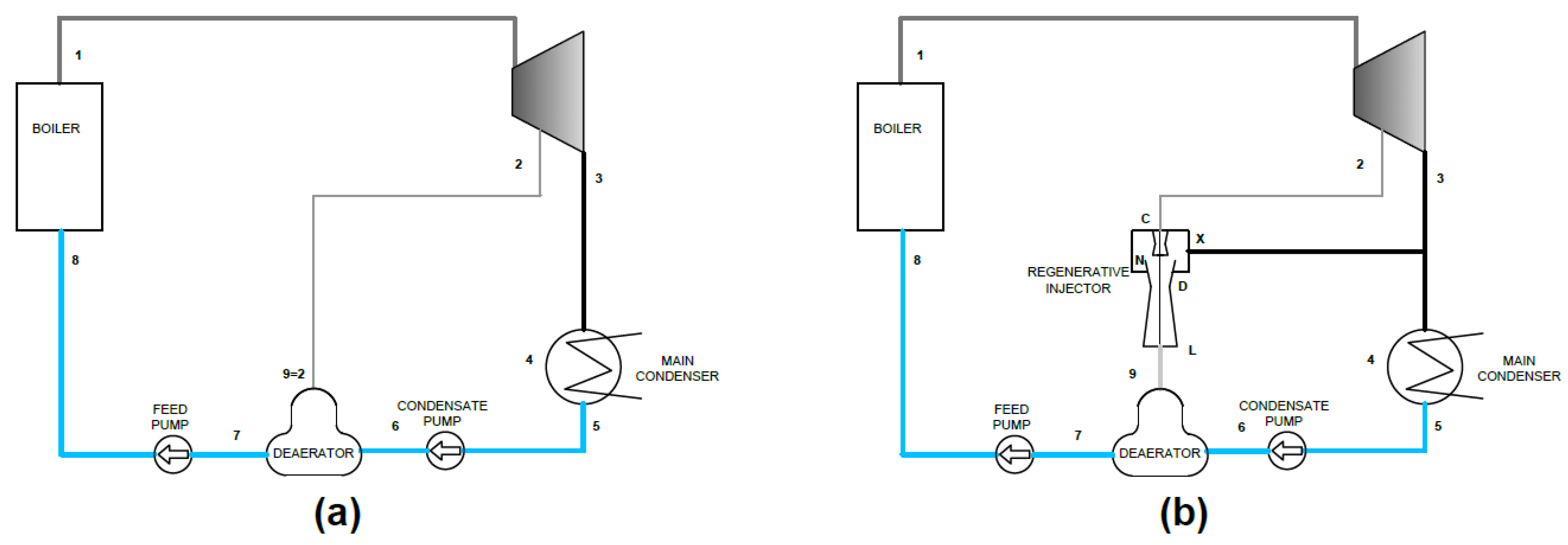
In conclusion of previous research, a mathematical model of the regenerative steam jet injector was presented [1,2,4] as a solution for the useful utilization of exhaust steam for turbines. The proposed suggestion assumed the use of steam jet injectors for mixing fluxes of low-pressure exhaust steam with bleed steam from the main turbine used as a drive medium for the injectors. In previous research, only one stage units were considered (Figure 1b).
The results of the calculation indicate that it is possible to increase the thermal efficiency of a simple system (regeneration degree 0.6–0.9) by applying a steam jet injector for the same parameters of the cycle [1,4]. As a result of the decreased steam bleed demand, and, at the same time, the increase of the available enthalpy drop in the turbine, the thermal efficiency of the thermodynamic cycle increases. However, to obtain the desired outlet steam pressure from the regenerative injector, the drive steam of a relatively high energy level is required. The application of the higher steam bleed pressure results in the decrease of the available enthalpy drop in the turbine. Based on the results of further research, the usage of a single stage steam jet injector is limited to the feed water temperature of 110 °C. For higher temperatures of feed water, a higher heating steam pressure (on the outlet from the injector) is required. To obtain the desired pressure two-stage regenerative steam, jet injectors can be used.
2. A Mathematical Model of a Two-Stage Steam Jet Injector Unit in the Main Boiler Regenerative Feed Water System
The results of the research presented in the first chapter indicate the validity of the use of regenerative steam jet injectors in the regenerative feed water systems. It has also been shown that the use of higher temperatures, due to the steam saturation pressure, requires the use of steam bleeds to drive the injectors from higher energy levels. In this case, the available enthalpy drop in the turbine is significantly reduced, which is not compensated by the utilization of the latent heat of the exhaust steam. Thus, ultimately, the degree of regeneration of the system is lower than with a direct feed from a suitably selected steam bleed.
Therefore, the analysis covered the possibility of using two-stage injectors units in order to obtain adequate heating steam pressures at the inlet to the heat exchangers.
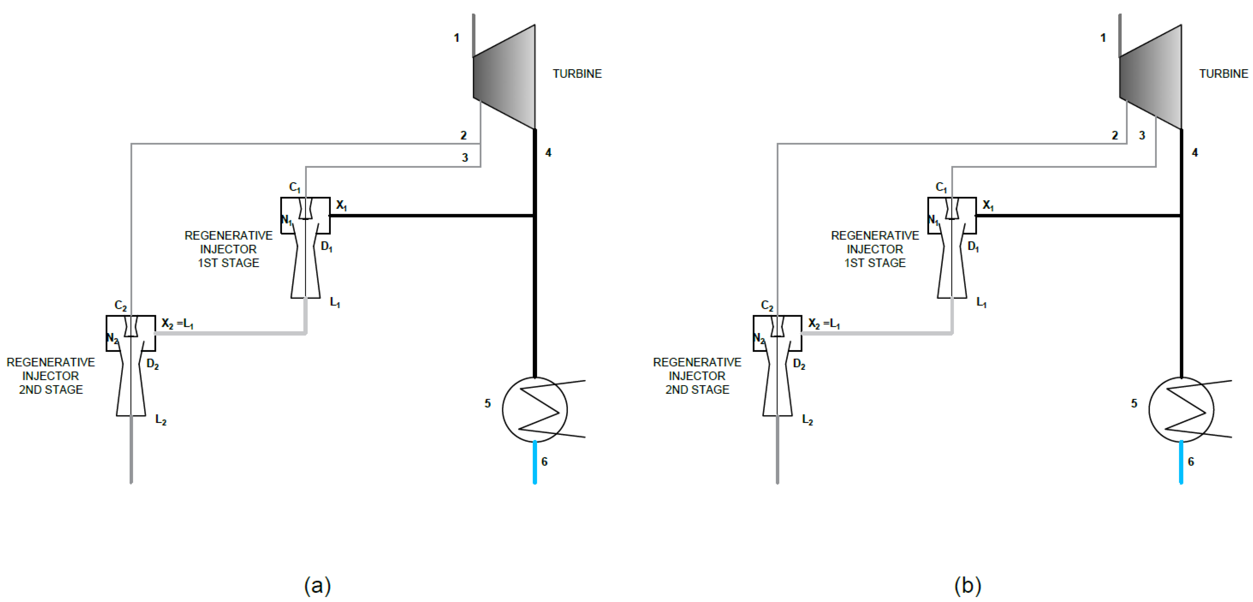
In order to conduct comparative tests of systems using two-stage compression of the exhaust steam from the turbine, the parameters of the injector systems for two variants were determined. In the first one, shown in Figure 2a, both injectors are driven from the same steam bleed. In the second variant (the thermal flow diagram is shown in Figure 2b), each injector is driven by steam from a different energy level. Due to the available pressure drop in the nozzle of the unit, it is expedient to use the steam from a lower energy level for the first stage injector.
2.1. An Algorithm of a Regenerative Two-Stage Steam Jet Injector Calculation
For the purposes of the analysis, the two-stage injector unit was treated as two separate injector devices, shown in Figure 2. The thermal flow calculations of the mathematical model were performed with the following assumptions [12,13]:
- the working medium is superheated steam, assumed to be a semi-perfect gas,
- the gas drawn from the condenser is wet steam,
- compression and expansion processes are polytrophic transformations,
- the steam ejection process takes place at a constant pressure equal to the pressure in the suction line (the error caused by the non-uniform pressure field in the mixing chamber was taken into account by the mixing chamber velocity loss coefficient φ2),
- in the heat balance of the ejection process, the kinetic energy of ejected steam was omitted, and
- the real velocity distribution along the radius was taken into account by the unevenness coefficient.
2.2. Determination of the Operating Parameters of a Two-Stage Injector Unit
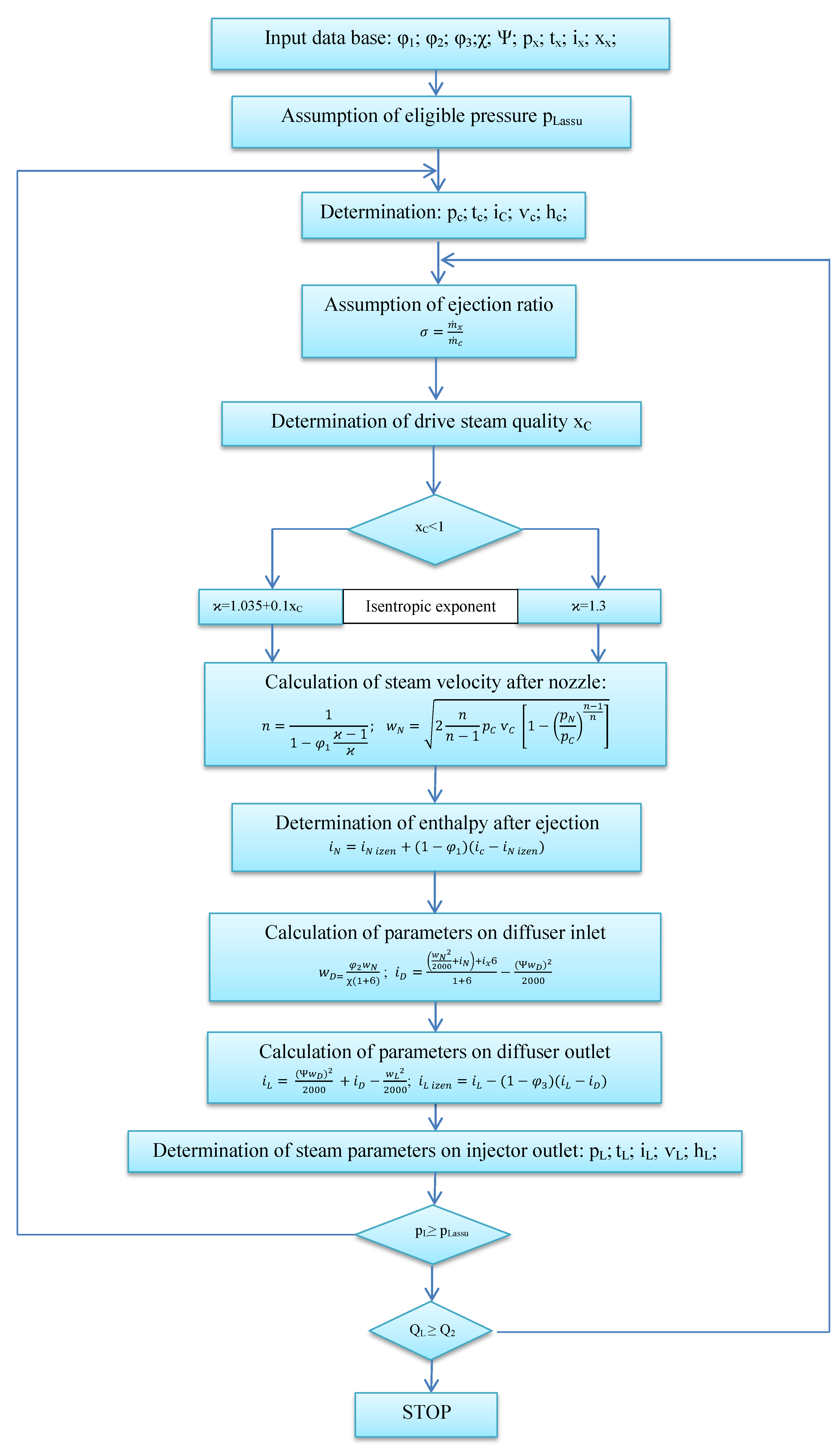
The operating parameters of a two-stage injector unit were determined in accordance with the algorithm shown in Figure 3.
For the multivariate calculations, the measured operation parameters of the 6.6 barA steam bleed as well as the parameters of the 3.0 and 10 barA bleeds determined based on the expansion curve were taken.
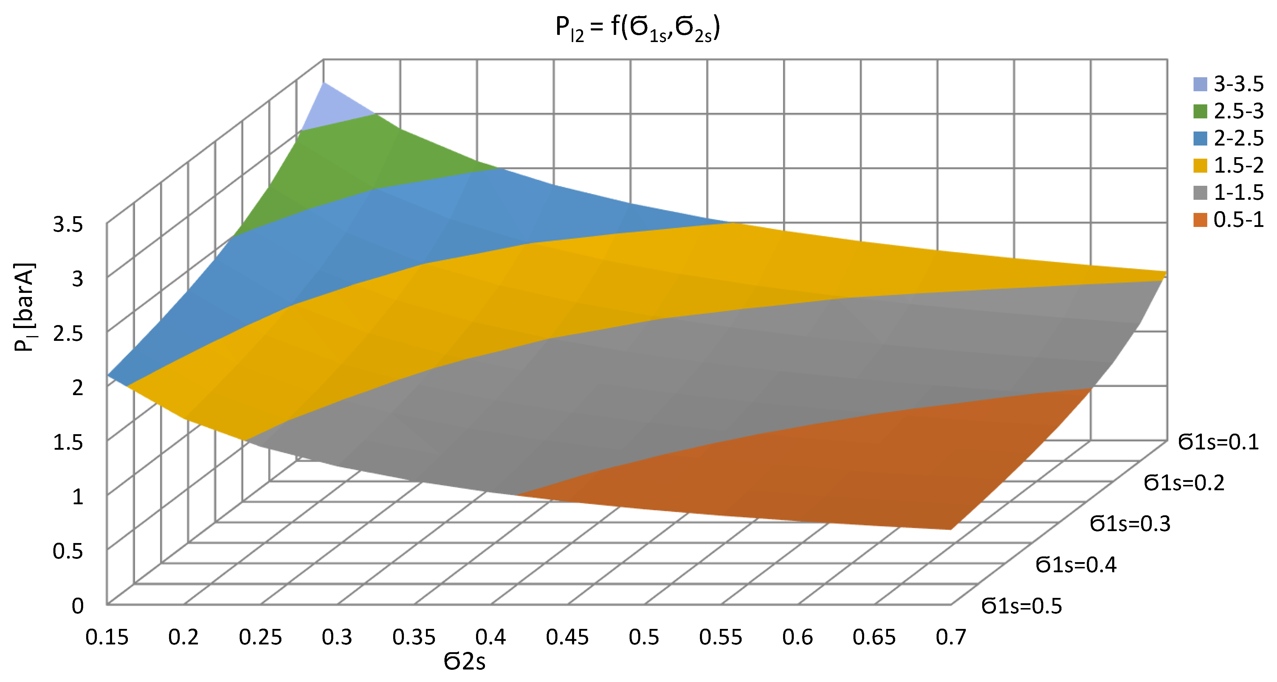
The results of calculations of the two-stage injector unit driven by the steam bleeds of 3.0 and 6.6 barA are shown in Figure 4. In this system, using an ejection ratio for the first stage , and for the second stage, it is possible to obtain a steam pressure of 2.41 barA and a temperature of 223.1 °C on the outlet from the injector.
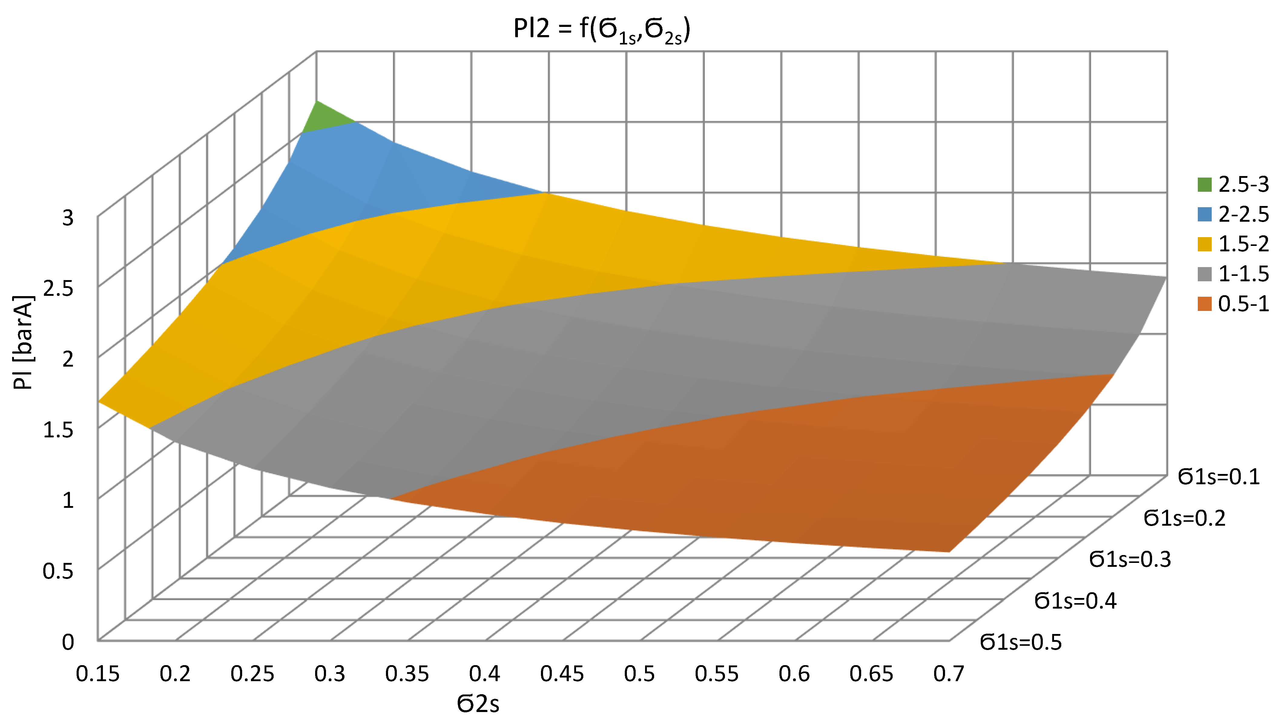
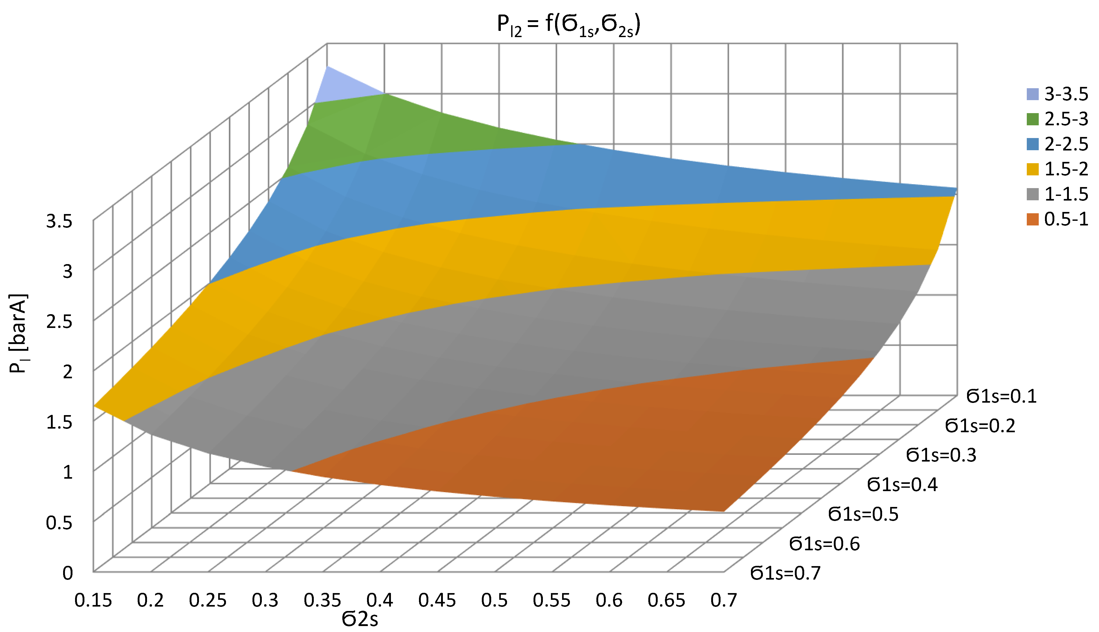
Using the bleed steam with a pressure of 3.0 barA for the first stage and 10 barA for the second stage, with the ejection ratios and , respectively, it is possible to obtain a steam with a pressure of 2.97 barA and a temperature of 259.5 °C. Figure 5 shows the relation between the steam pressure on the outlet from two-stage injector unit and the injection ratio of individual injectors.
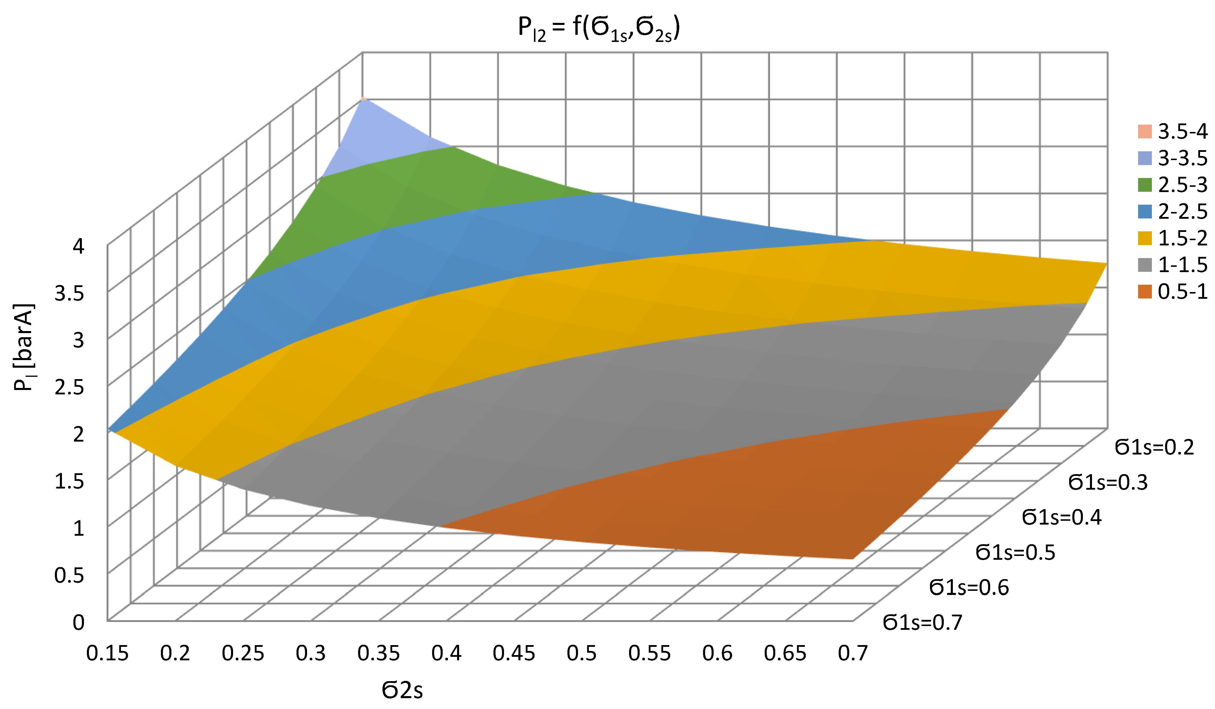
In Figure 6 and Figure 7, the relations of the possible-to-obtain steam pressures on the outlet from a two-stage injector unit is presented for both injectors driven by 6.6 barA and 6.6 and 10 barA, respectively. For the first variant, using the ejection ratio from the range of 0.143–0.667, it is possible to obtain steam with a pressure of 2.89 barA and a temperature of 231.6 °C. When driven by bleed steam pressure of 6.6 and 10 barA, the outlet steam pressure of 3.57 barA and a temperature of 268 °C can be obtained.
The determined parameters of the outlet steam of the injectors were used as input data for the heat balance calculation of systems with the use of overpressure heat exchangers.
3. An Analysis of Application of Steam Injectors in a Boiler Regenerative Feed Water System
Based on the operating parameters of the injector unit as input data, a multivariate analysis of the effects of using two-stage injector units was carried out. The main criterion for assessing the use of regenerative systems is their degree of regeneration, defined as the relative increase of efficiency,
where is the enthalpy efficiency of the reference cycle and is the efficiency of the modified cycle. In order to determine the degree of regeneration, the sets of heat balance Equations (8), (10), (15), and (18) were solved using the Cramer method.
3.1. Reference System
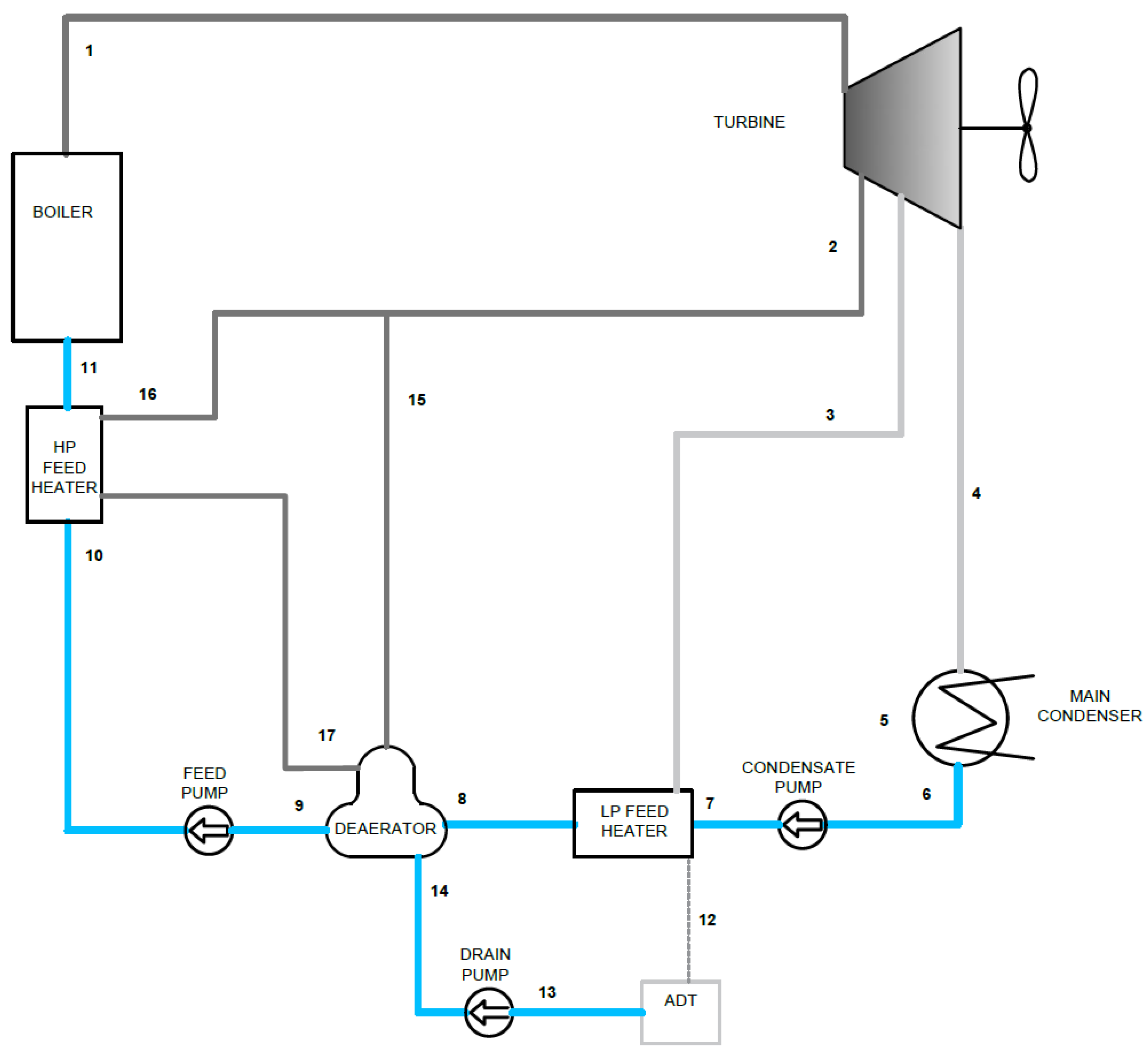
Figure 8 shows a thermal flow diagram of the reference system, modelled using the operating parameters of the turbine drive system of an LNG tanker from 2003. The regenerative feed water heating system consists of three heat exchangers (LP (Low Pressure) Feed water, deaerator, and HP (High Pressure) feed water heater) fed from two steam bleeds of the main propulsion turbine. The parameters of the working medium condition in the control planes are presented in Table 3.
The mathematical model of the reference system is described using the system of balance Equations (8).
where is the mas flow of the medium and index n corresponds to the number of the individual control plane.
The enthalpy efficiency of the system is represented by:
3.2. Application of Steam Jet Injectors in Complex Regenerative Feed Water Systems
To compare the results of the application of the two-stage injectors in the feed water system, the versions of the system constituting reference system modifications were modelled as listed below:
- A system of single-stage injectors with three heat exchangers, including two heat exchangers fed by regenerative injectors.
- A system with the use of two-stage steam injectors and three heat exchangers.
- A complex system using both single-stage and two-stage steam injectors and five heat exchangers.
3.2.1. Application of Single-Stage Injectors
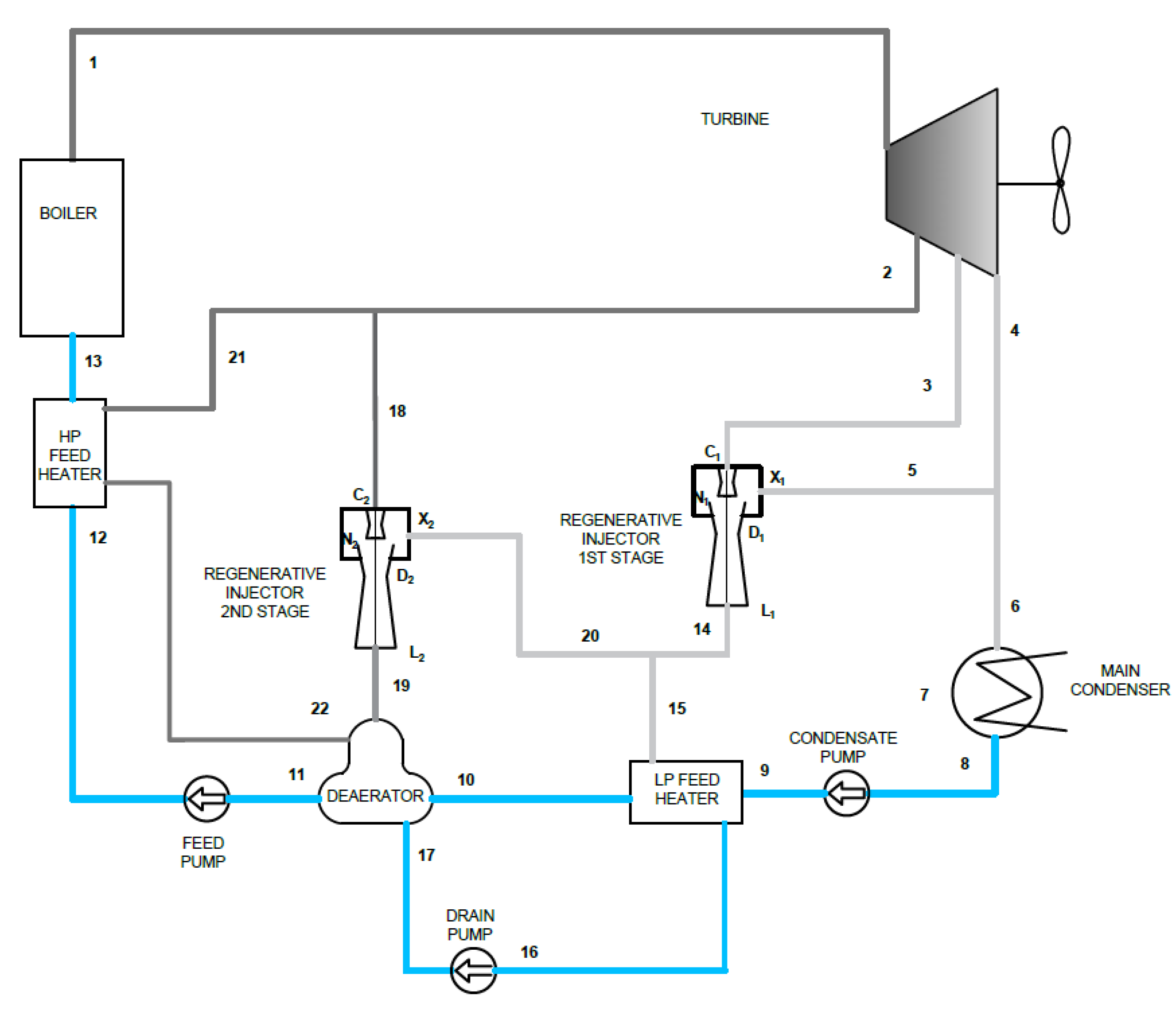
Figure 9 shows a thermal-flow diagram of the modified system in which two single stage steam injectors were used. The first injector supplies a vacuum heat exchanger in which the boiler feed water is heated to the temperature of 80 °C. The second injector feeds the deaerator in which, due to the achievable injector outlet steam pressure, the temperature of water heating is 100 °C. Further heating of the water, as in the reference system, takes place in an overpressure heat exchanger supplied directly from the 6.6 barA steam bleed up to a temperature of 140 °C. Table 4 presents the thermodynamic parameters of the medium in individual control planes of the cycle (1,2,3,…n), and control planes of injectors (Ci,Xi,Li, where i stands for injector number).
The mathematical model of the system is described by the system of the following balance Equations (10).
The mass flow of the driven and drawn steam of the injectors can be determined based on the transformed definition of the ejection ratio (Figure 3):
Therefore, the calculated efficiency of the system is:
and as a result of the modification applied, the degree of system regeneration corresponds to
The application of the modification resulted in the part of the waste heat that was previously lost in the condenser being usefully applied to heat the boiler feed water. The mass flows of the required bleed steam feeding heat exchangers also decreased, thus increasing the available enthalpy drop in the turbine.
3.2.2. Application of Two-Stage Regenerative Injectors
In a single-stage steam injector system, a significant portion of the heat used to heat the feed water is supplied in the overpressure heat exchanger. The maximum steam pressure on the outlet of the injector fed from the 6.6 barA bleed is 1.061 barA, allowing the water to be heated in the mixed heat exchanger up to 100 °C.
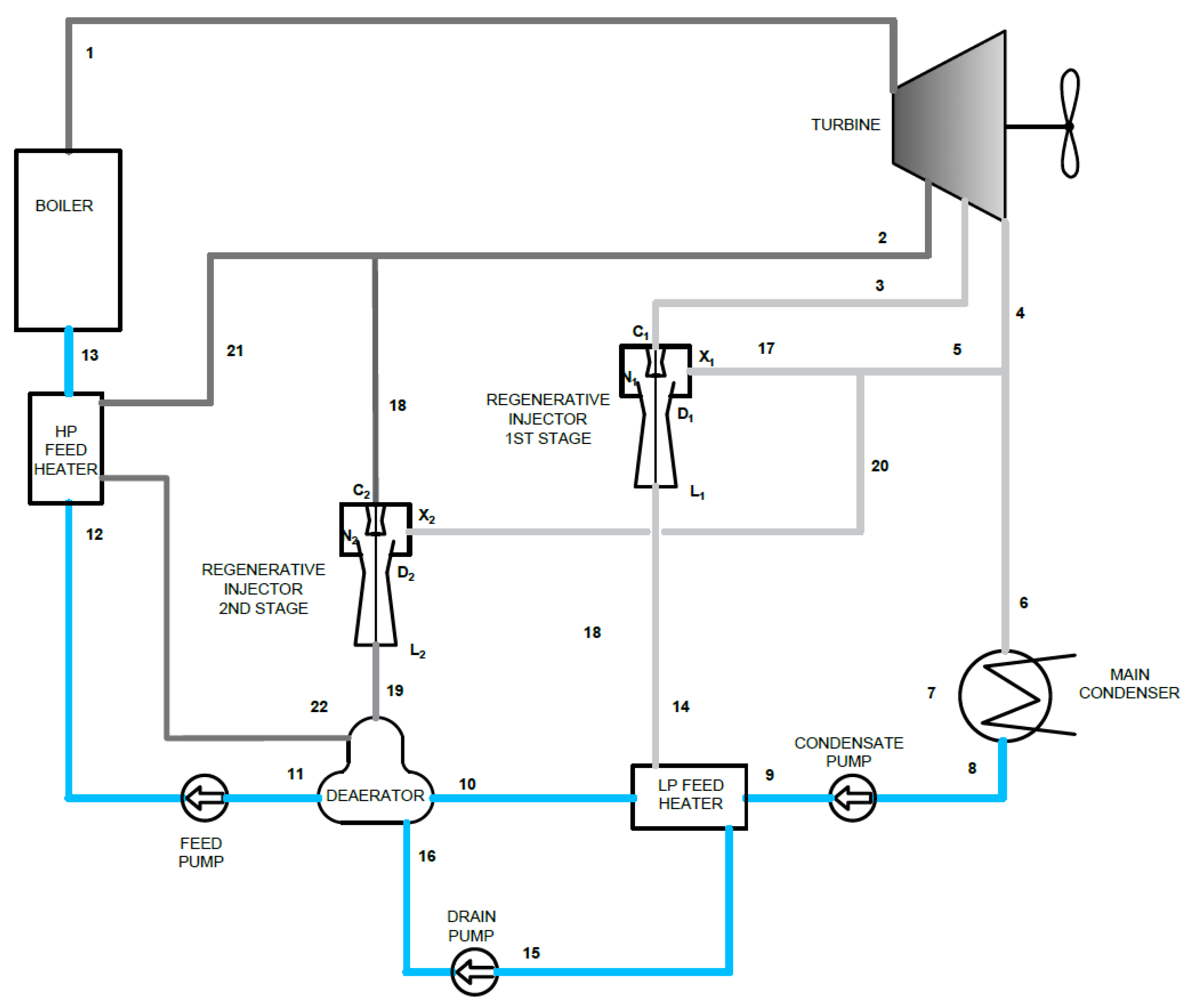
To obtain the temperatures of the feed water, it is necessary to use a two-stage injector unit. Figure 10 shows a thermal flow diagram of a system with a two-stage injector unit. The steam flux from the first stage injector feeds a vacuum heat exchanger in which the boiler water is heated up to a temperature of 80 °C and, at the same time, is partially drawn by the second stage injector.
The parameters of the steam states in the individual control planes are presented in Table 5, along with the values of mass flows determined on the basis of the system of balance Equations (15) and (11)–(12).
Calculated from the following relationship, the efficiency of the system is:
Due to the modification, the regeneration degree of the system is:
As a result of the application of a two-stage steam jet injector unit, it is possible to obtain a higher steam pressure on the outlet of the injector feeding the deaerator, and thus to heat the water in it to a temperature of 120 °C. The use of a two-stage unit, despite a significant increase in the water heating temperature in the exchangers fed by regenerative injectors, slightly changes the amount of the recovered latent heat of the exhaust steam from the turbine. Thus, the level of regeneration of the system increases slightly from 0.503% to 0.518%.
3.2.3. Application of Combined Single- and Two-Stage Injectors Units in a Complex Regenerative System
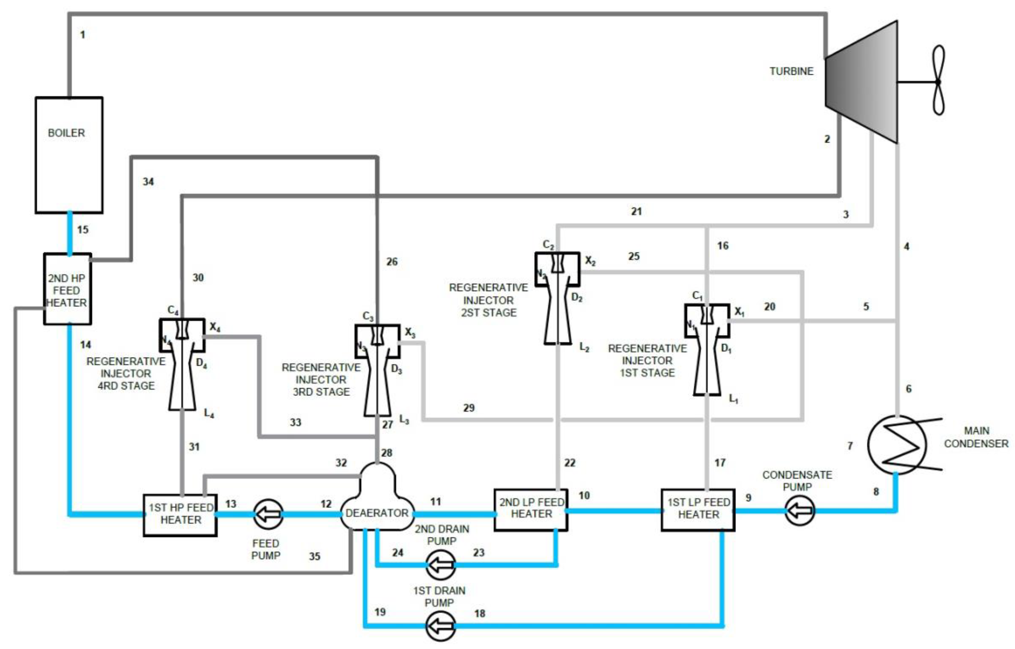
Looking for further possibilities of waste heat utilization and the improvement of cycle efficiency, systems with the use of additional heat exchangers were considered. The use of injectors allows, through the selection of the ejection ratio, to optimize the operation of the exchangers, selecting the pressure of steam supplying the exchanger as close as possible to the saturation pressure, for the assumed temperatures. Figure 11 shows a variant of a complex system consisting of five heat exchangers. The system uses two single-stage injectors and one two-stage injection unit. The state parameters in individual control planes are presented in Table 6.
The mathematical model of a complex system is described by the system of Equations (18) and (11)–(12).
The calculated efficiency of the system is:
with the regeneration degree of the system equal to:
The use of additional heat exchangers and a two-stage injector unit allows for heating of the boiler feed water to the temperature of 125 °C, thus reducing the required mass flow of the bleed steam for the last heat exchanger. However, due to the low ejection ratio on injectors of the fourth and fifth stages, the recovery of waste energy in the form of a mass flow of the drawn turbine exhaust steam is negligible and does not significantly increase the efficiency.
4. Discussion
The use of more heaters than in the reference system would lead to a more rational use of heat by increasing the available enthalpy drop in the turbine and increasing the degree of use of the heat of condensation to heat the feed water. The degree of regeneration of the complex system was 0.882% while maintaining the same temperature of the boiler feed water and the use of steam bleeds with the same parameter values as in the reference system. The required bleed steam streams decrease, while the heat deficiency resulting from the reduced bleed steam streams is balanced by the latent heat of the turbine exhaust steam. However, such modification leads to a complexity of the boiler water heating system.
The use of two-stage injector units enables their use for higher levels of heating of the feed water. However, the efficiency gains in this variant are much smaller than in the case of single-stage systems for lower temperatures. Therefore, it would be advisable to consider the justifiability of using systems with two-stage injectors from an economic point of view.
Moreover, in the course of the multivariate calculations, the possibility of using an additional exchanger was considered, which would desuperheat the significantly superheated steam from the second stage injector. However, due to the relatively low mass flow of that steam, the efficiency gains are relatively low.
The highest regeneration degree increases due to the modifications were obtained for exchangers operating in the range of the boiler feed water temperature of up to 80 °C, where higher ejection ratios and the bleed steam from lower energy levels can be used. The use of injectors for higher temperatures results in unsatisfactory increases in the degree of system regeneration of . However, the use of injectors in auxiliary systems can be considered where technological processes require steam of low technical parameters, such as gland steam, heating steam for vacuum fresh water generators, boiler combustion air heaters, or water heaters in district heating systems.
Author Contributions
Conceptualization, S.G and A.A.; methodology, S.G.; formal analysis, S.G.; investigation, S.G.; resources, S.G.; writing—original draft preparation, S.G.; writing—review and editing, A.A.; visualization, S.G.; supervision, A.A. All authors have read and agreed to the published version of the manuscript.
Funding
This research received no external funding.
Institutional Review Board Statement
Not applicable.
Informed Consent Statement
Not applicable.
Conflicts of Interest
The authors declare no conflict of interest.
References
- Adamkiewicz, A.; Grzesiak, S. Determination of The Operating Parameters of Steam Jet Injectors for A Main Boiler’s Regenerative Feed Water System. Zesz. Nauk. Akad. Mor. w Szczec. 2019, 60, 171–176. [Google Scholar]
- Adamkiewicz, A.; Grzesiak, S. Identification of Waste Heat Energy Sources of a Conventional Steam Propulsion Plant of LNG Carrier. Arch. Thermodyn. 2019, 40, 195–210. [Google Scholar]
- Grzesiak, S. Alternative Propulsion Plants for Modern LNG Carriers. New Trends Prod. Eng. 2018, 1, 399–408. [Google Scholar] [CrossRef] [Green Version]
- Grzesiak, S.; Adamkiewicz, A. Application of Steam Jet Injector for Latent Heat Recovery of Marine steam Turbine Propulsion Plant. New Trends Prod. Eng. 2018, 1, 235–246. [Google Scholar] [CrossRef] [Green Version]
- Ammar, N.R. Environmental and cost-effectiveness comparison of dual fuel propulsion options for emissions reduction onboard LNG carriers. Shipbuilding 2019, 70, 61–77. [Google Scholar] [CrossRef]
- Baressi Šegota, S.; Lorencin, I.; Anđelić, N.; Mrzljak, V.; Car, Z. Improvement of Marine Steam Turbine Conventional Exergy Analysis by Neural Network Application. J. Mar. Sci. Eng. 2020, 8, 884. [Google Scholar] [CrossRef]
- Ekanem Attah, E.; Bucknall, R. An analysis of the energy efficiency of LNG ships powering options using the EEDI. Ocean. Eng. 2015, 110, 62–74. [Google Scholar] [CrossRef]
- Fernández, I.; Gómez, M.; Gómez, J.; Insua, A. Review of propulsion systems on LNG carriers. Renew. Sustain. Energy Rev. 2017, 67, 1395–1411. [Google Scholar] [CrossRef]
- IGU World LNG Report. Available online: http://www.igu.org (accessed on 1 August 2018).
- Patel, M.; Nath, N. Improve steam turbine efficiency. Hydrocarb. Process. 2000, 79, 85–90. [Google Scholar]
- Szargut, J. Exergy Method—Technical and Ecological Applications; WIT Press: Southampton, UK, 2005. [Google Scholar]
- Gryboś, R. Regeneracja ciepła w siłowni z turbiną bezupustową. Zesz. Nauk. Politech. Śląskiej 1956, 1, 59–80. [Google Scholar]
- Hegazy, A. Possible Waste Heat Recovery in the Condenser of a Regenerative Steam Cycle. J. Therm. Sci. Technol. 2007, 2, 1–12. [Google Scholar] [CrossRef] [Green Version]
Figure 1.
Thermal flow diagram of the proposed model: (a) Clausius–Rankine cycle with a regenerative heater (deaerator) feed from steam bleed; (b) Clausius–Rankine cycle with a regenerative heater (deaerator) feed by regenerative injector. Reproduced with permission from the MAPE Conference Organizing Team, published by New Trends in Production Engineering 2018.

Figure 2.
A thermal flow diagram of a two-stage steam jet injector driven by (a) the same bleed; (b) two different bleeds.
Figure 2.
A thermal flow diagram of a two-stage steam jet injector driven by (a) the same bleed; (b) two different bleeds.

Figure 3.
Algorithm of the regenerative injector calculation. Reproduced with permission from the MAPE Conference Organizing Team, published by New Trends in Production Engineering 2018.
Figure 3.
Algorithm of the regenerative injector calculation. Reproduced with permission from the MAPE Conference Organizing Team, published by New Trends in Production Engineering 2018.

Figure 4.
Relation of the steam pressure on the outlet from the two-stage injector unit driven by steam bleads 3.0 and 6.6 barA in the function of the ejection ratio .
Figure 4.
Relation of the steam pressure on the outlet from the two-stage injector unit driven by steam bleads 3.0 and 6.6 barA in the function of the ejection ratio .

Figure 5.
Relation of the steam pressure on the outlet from the two-stage injector unit driven by steam bleads 3.0 and 10 barA in the function of ejection ratio .
Figure 5.
Relation of the steam pressure on the outlet from the two-stage injector unit driven by steam bleads 3.0 and 10 barA in the function of ejection ratio .

Figure 6.
Relation of the steam pressure on the outlet from the two-stage injector unit driven by steam bleads 6.6 barA for both injectors in the function of the ejection ratio .
Figure 6.
Relation of the steam pressure on the outlet from the two-stage injector unit driven by steam bleads 6.6 barA for both injectors in the function of the ejection ratio .

Figure 7.
Relation of the steam pressure on the outlet from the two-stage injector unit driven by steam bleads 6.6 and 10 barA in the function of the ejection ratio .
Figure 7.
Relation of the steam pressure on the outlet from the two-stage injector unit driven by steam bleads 6.6 and 10 barA in the function of the ejection ratio .

Figure 8.
A thermal flow diagram of a reference cycle.

Figure 9.
Thermal flow diagram of the regenerative cycle with single-stage regenerative injectors.

Figure 10.
Thermal flow diagram of the regenerative cycle with two-stage injectors.

Figure 11.
A thermal flow diagram of a complex regenerative cycle.


Table 1.
Criterion assessment of modern LNG carrier power plants. Reproduced with permission from the MAPE Conference Organizing Team, published by New Trends in Production Engineering 2018.
Table 1.
Criterion assessment of modern LNG carrier power plants. Reproduced with permission from the MAPE Conference Organizing Team, published by New Trends in Production Engineering 2018.
| Plant Type | Environmental Compliance | Thermal Efficiency | Fuel System | Reliability | OPEX |
|---|---|---|---|---|---|
| Steam Plant |
| = 0.30 = 0.41 | 3 fuel modes: Gas only Dual fuel (any ratio) FO only | High Low redundancy | Low maintenance costs High Fuel costs |
| Dual/Triple Fuel Diesel Electric |
| = 0.42 | 2 modes: Fuel only Gas mode (min load 10% + 1% pilot fuel) | <Steam plant High redundancy | High Engine maintenance costs |
| Diesel with Reliquification |
| = 0.47 | No gas burning (min load 10% +3–5% pilot fuel) | <Steam plant propulsion redundancy | High Engine maintenance costs |
| Dual Fuel Slow Speed Diesel |
| = 0.51 | FO only (MDO/HFO) Gas shear mode | <Steam plant propulsion redundancy | High Engine and compressors maintenance costs |
| Combine Gas and Steam Turbine |
| = 0.41 | FO only (MDO) Gas burning (3–5% pilot fuel) | Not proven for LNG carriers | <DFDE >Steam plant |
Table 2.
Results of the quality assessment of the main waste heat energy sources. Reproduced with permission from the MAPE Conference Organizing Team, published by New Trends in Production Engineering 2018.
Table 2.
Results of the quality assessment of the main waste heat energy sources. Reproduced with permission from the MAPE Conference Organizing Team, published by New Trends in Production Engineering 2018.
| Flow | Energy Flux | Press. Abs. | Temp | Enthalpy | Steam Quality | Exergy | ψ Temp | ψ f(b,i) | |
|---|---|---|---|---|---|---|---|---|---|
| [kg/h] | [kJ/h] | [barA] | [°C] | [kJ/kg] | [-] | [kJ/kg] | [-] | [-] | |
| MT Condenser Losses | 81,388.6 | 175,473,867.3 | 0.066 | 38 | 2294 | 0.888 | 1926.4 | 0.132 | 0.8936 |
| TA Condenser Losses | 5715.8 | 13,226,381.8 | 0.075 | 40 | 2452 | 0.95 | 2069.7 | 0.175 | 0.8945 |
| Exhaust Losses | 157,827.5 | 44,935,857.3 | 1.05 | 155 | 285 | xxx | 139.2 | 0.806 | 0.5461 |
Table 3.
Thermodynamic parameters of the working fluid in control planes of the reference cycle.
| Control Plane | P abs | t | i | |
|---|---|---|---|---|
| [barA] | [°C] | [kJ/kg] | [kg/s] | |
| 1 | 59.5 | 520 | 3470 | 1.0000 |
| 2 | 6.6 | 245 | 2943 | 0.0972 |
| 3 | 3 | 170 | 2803 | 0.0686 |
| 4 | 0.066 | 38 | 2300 | 0.8342 |
| 5 | 0.05 | 32 | 2290 | 0.8342 |
| 6 | 0.05 | 32 | 138 | 0.8342 |
| 7 | 10 | 32 | 138 | 0.8342 |
| 8 | 10 | 80 | 335.8 | 0.8342 |
| 9 | 1.99 | 120 | 503.8 | 1.0000 |
| 10 | 70 | 120 | 503.8 | 1.0000 |
| 11 | 70 | 140 | 593.5 | 1.0000 |
| 12 | 1 | 85 | 398.1 | 0.0686 |
| 13 | 10 | 85 | 398.1 | 0.0686 |
| 14 | 10 | 85 | 398.1 | 0.0686 |
| 15 | 6.6 | 245 | 2943 | 0.0587 |
| 16 | 6.6 | 245 | 2943 | 0.0385 |
| 17 | 4.16 | 145 | 610.6 | 0.0385 |
Table 4.
Thermodynamic parameters of the working fluid in the control planes of the regenerative cycle with single-stage injectors.
Table 4.
Thermodynamic parameters of the working fluid in the control planes of the regenerative cycle with single-stage injectors.
| Control Plane | P abs | t | i | |
|---|---|---|---|---|
| [barA] | [°C] | [kJ/kg] | [kg/s] | |
| 1 | 59.5 | 520 | 3470 | 1.0000 |
| 2 | 6.6 | 245 | 2943 | 0.0958 |
| 3 = C1 | 3 | 170 | 2803 | 0.0596 |
| 4 | 0.066 | 38 | 2300 | 0.8446 |
| 5 | 0.066 | 38 | 2300 | 0.0129 |
| 6 | 0.05 | 32 | 2290 | 0.8316 |
| 7 | 0.05 | 32 | 2290 | 0.8316 |
| 8 | 0.05 | 32 | 138 | 0.8316 |
| 9 | 10 | 32 | 138 | 0.8316 |
| 10 | 10 | 80 | 335.8 | 0.8316 |
| 11 | 1.061 | 100 | 419.2 | 1.0000 |
| 12 | 70 | 100 | 419.2 | 1.0000 |
| 13 | 70 | 140 | 593.5 | 1.0000 |
| 14 = L1 | 0.611 | 124.4 | 2729.3 | 0.0695 |
| 15 | 0.611 | 85 | 363.5 | 0.0695 |
| 16 | 10 | 85 | 363.5 | 0.0695 |
| 17 = X1 | 0.066 | 38 | 2300 | 0.0099 |
| 18 = C2 | 6.6 | 245 | 2943 | 0.0211 |
| 19 = L2 | 1.061 | 192,7 | 2860.8 | 0.0241 |
| 20 = X2 | 0.066 | 38 | 2300 | 0.0030 |
| 21 | 6.6 | 245 | 2943 | 0.0747 |
| 22 | 4.16 | 145 | 610.6 | 0.0747 |
| Assumed Ejection Ratio | Ϭ 1 | 0.167 | ||
| Ϭ 2 | 0.143 |
Table 5.
Thermodynamic parameters of the working fluid in the control planes of the regenerative cycle with two-stage injectors.
Table 5.
Thermodynamic parameters of the working fluid in the control planes of the regenerative cycle with two-stage injectors.
| Control Plane | P abs | t | i | |
|---|---|---|---|---|
| [barA] | [°C] | [kJ/kg] | [kg/s] | |
| 1 | 59.5 | 520 | 3470 | 1.0000 |
| 2 | 6.6 | 245 | 2943 | 0.0889 |
| 3 = C1 | 3 | 170 | 2803 | 0.0682 |
| 4 | 0.066 | 38 | 2300 | 0.8429 |
| 5 | 0.066 | 38 | 2300 | 0.0114 |
| 6 | 0.066 | 38 | 2300 | 0.8315 |
| 7 | 0.05 | 32 | 2290 | 0.8315 |
| 8 | 0.05 | 32 | 138 | 0.8315 |
| 9 | 10 | 32 | 138 | 0.8315 |
| 10 | 10 | 80 | 335.8 | 0.8315 |
| 11 | 1.99 | 120 | 503.8 | 1.0000 |
| 12 | 70 | 120 | 503.8 | 1.0000 |
| 13 | 70 | 140 | 593.5 | 1.0000 |
| 14 = L1 | 0.611 | 124.4 | 2729.3 | 0.0796 |
| 15 | 0.611 | 124.4 | 2729.3 | 0.0695 |
| 16 | 0.611 | 86.4 | 361.9 | 0.0695 |
| 17 = X1 | 10 | 86.4 | 361.9 | 0.0695 |
| 18 = C2 | 0.611 | 124.4 | 2729.3 | 0.0101 |
| 19 = L2 | 6.6 | 245 | 2943 | 0.0505 |
| 20 = X2 | 2.032 | 217.4 | 2905.6 | 0.0606 |
| 21 | 6.6 | 245 | 2943 | 0.0385 |
| 22 | 4.16 | 145 | 610.6 | 0.0385 |
| Assumed Ejection Ratio | Ϭ 1 | 0.167 | ||
| Ϭ 2 | 0.2 |
Table 6.
Thermodynamic parameters of the working fluid in the control planes of a complex regenerative cycle.
Table 6.
Thermodynamic parameters of the working fluid in the control planes of a complex regenerative cycle.
| Control Plane | P abs | t | i | |
|---|---|---|---|---|
| [barA] | [°C] | [kJ/kg] | [kg/s] | |
| 1 | 59.5 | 520 | 3470 | 1.0000 |
| 2 | 6.6 | 245 | 2943 | 0.0945 |
| 3 | 3 | 170 | 2803 | 0.0532 |
| 4 | 0.066 | 38 | 2300 | 0.8523 |
| 5 | 0.066 | 38 | 2300 | 0.0226 |
| 6 | 0.066 | 38 | 2300 | 0.8297 |
| 7 | 0.05 | 32 | 2290 | 0.8297 |
| 8 | 0.05 | 32 | 138 | 0.8297 |
| 9 | 10 | 32 | 138 | 0.8297 |
| 10 | 10 | 61.7 | 259.1 | 0.8297 |
| 11 | 10 | 81.4 | 341.6 | 0.8297 |
| 12 | 1.06 | 101.3 | 424.5 | 1.0000 |
| 13 | 70 | 101.3 | 424.5 | 1.0000 |
| 14 | 70 | 125.7 | 532.7 | 1.0000 |
| 15 | 70 | 140 | 593.5 | 1.0000 |
| 16 = C1 | 3 | 170 | 2803 | 0.0285 |
| 17 = L1 | 0.271 | 73.4 | 2633.5 | 0.0427 |
| 18 | 0.271 | 66.7 | 279.6 | 0.0427 |
| 19 | 10 | 66.7 | 279.6 | 0.0427 |
| 20 = x1 | 0.066 | 38 | 2300 | 0.0142 |
| 21 = c2 | 3 | 170 | 2803 | 0.0248 |
| 22 = L2 | 0.611 | 124.4 | 2729.3 | 0.0289 |
| 23 | 0.611 | 86.4 | 361.9 | 0.0289 |
| 24 | 10 | 86.4 | 361.9 | 0.0289 |
| 25 = x2 | 0.066 | 38 | 2300 | 0.0041 |
| 26 = c3 | 6.6 | 245 | 2943 | 0.0295 |
| 27 = l3 | 1.061 | 192.7 | 2860.8 | 0.0337 |
| 28 | 1.061 | 192.7 | 2860.8 | 0.0272 |
| 29 | 0.066 | 38 | 2300 | 0.0042 |
| 30 = c4 | 6.6 | 245 | 2943 | 0.0390 |
| 31 = L1 | 2.762 | 230.7 | 2929.5 | 0.0455 |
| 32 | 2.762 | 130.7 | 549.5 | 0.0455 |
| 33 = x4 | 1.061 | 192.7 | 2860.8 | 0.0065 |
| 34 | 6.6 | 245 | 2943 | 0.0261 |
| 35 | 4.16 | 145 | 610.6 | 0.0261 |
| Assumed Ejection Ratio | Ϭ 1 | 0.500 | ||
| Ϭ 2 | 0.167 | |||
| Ϭ 3 | 0.143 | |||
| Ϭ 4 | 0.167 |
Publisher’s Note: MDPI stays neutral with regard to jurisdictional claims in published maps and institutional affiliations. |
© 2021 by the authors. Licensee MDPI, Basel, Switzerland. This article is an open access article distributed under the terms and conditions of the Creative Commons Attribution (CC BY) license (https://creativecommons.org/licenses/by/4.0/).
Share and Cite
MDPI and ACS Style
Grzesiak, S.; Adamkiewicz, A. Application of a Two-Stage Steam Jet Injector Unit for Latent Heat Recovery of a Marine Steam Turbine Propulsion Plant. Appl. Sci. 2021, 11, 5511. https://0-doi-org.brum.beds.ac.uk/10.3390/app11125511
AMA Style
Grzesiak S, Adamkiewicz A. Application of a Two-Stage Steam Jet Injector Unit for Latent Heat Recovery of a Marine Steam Turbine Propulsion Plant. Applied Sciences. 2021; 11(12):5511. https://0-doi-org.brum.beds.ac.uk/10.3390/app11125511
Chicago/Turabian StyleGrzesiak, Szymon, and Andrzej Adamkiewicz. 2021. "Application of a Two-Stage Steam Jet Injector Unit for Latent Heat Recovery of a Marine Steam Turbine Propulsion Plant" Applied Sciences 11, no. 12: 5511. https://0-doi-org.brum.beds.ac.uk/10.3390/app11125511
Note that from the first issue of 2016, this journal uses article numbers instead of page numbers. See further details here.