
New Optical Design Method of Floating Type Collimator for Microscopic Camera Inspection


1
Department of IT Convergence, Kumoh National Institute of Technology, Daehakro-61, Gumi 39177, Korea
2
Department of Optical Engineering, Kumoh National Institute of Technology, Gumi 39253, Korea
3
Department of Medical IT Convergence Engineering, Kumoh National Institute of Technology, Gumi 39253, Korea
*
Authors to whom correspondence should be addressed.
Appl. Sci. 2021, 11(13), 6203; https://0-doi-org.brum.beds.ac.uk/10.3390/app11136203
Submission received: 3 May 2021
/
Revised: 25 June 2021
/
Accepted: 28 June 2021
/
Published: 4 July 2021
(This article belongs to the Special Issue Geometrical Optics: Theoretical Achievements and Applications)
Abstract
:Featured Application
Microscopic Camera Inspection.
Abstract
Recently released mobile phone cameras are capable of photographing objects at a fairly close distance. In addition, the field angle from the camera has increased. To measure the resolution of a mobile phone camera, the target must be photographed. To measure the resolution according to the object distance change from a mobile phone camera with a wide field angle, the target size must be large, whereas the target position must be moved. However, the target size cannot be changed. A virtual object for the target was created using a collimator. Moving a part of the lens group constituting the collimator also changes the virtual object distance. If the amount of change in the virtual object distance is large, the resolution of the collimator may also change. Therefore, a collimator that maintains the resolution even when the distance of the virtual object changes is designed as a floating type in which two lens groups move. Therefore, we propose a new floating collimator optical system that can inspect the resolution of mobile phone cameras from infinity to a close range to compensate for aberrations caused by object distance changes.
1. Introduction
Phone cameras have become an essential component of mobile phones. In the past, a phone camera had only a single optical system installed, whereas several optical systems have been used in the latest mobile phone products. Such a phone camera is composed of an optical system with a wide field angle, normal field angle, and narrow field angle [1]. Therefore, the single focus lens used in such an optical system has the same function as a zoom lens in a digital camera. In addition, auto-focus in the phone camera is essential for accurately focusing the spots according to the object distance changes. Therefore, in the production process of a phone camera, it is necessary to check the resolution variation according to the object distance change.
The resolution of a phone camera can be tested using various methods. The first method involves measuring the modulation transfer function (MTF) of an optical system [2,3,4]. The second method involves photographing the target after assembling the optical system and image sensor [5]. Because the real target should be placed in front of the camera optics to be inspected, a wide space is required to photograph the target. To do so, the target is downsized, and a collimator is placed in front of the target [6]. Subsequently, a virtual image of the target must be created at a specific distance using the collimator. Figure 1 shows the optical layout for inspecting the camera optics using this collimator. A collimator is used to drastically reduce the space required for the inspection of the camera optics. The word “floating” is a very popular word in camera optics [7]. Optical systems that move two or more groups of lenses to correct the image distance are called “floating optics”. The optical system proposed in this paper changes the position of the virtual image by moving two or more lens groups.
The collimator, which can change the virtual image distance from a real target, is widely used in an optical inspection, such as optical resolution test of optical lens systems or surface inspection of optical instruments [8,9]. In the performance test of an optical system, the collimator is placed between the target, or test chart in some cases to inspect the lens system, collimating the incident test light to plane light source and changing the focal points [10,11,12,13]. In most cases, the target includes a light source to improve the test. The test light emitted from the sources passes through the transparent target or is reflected from the target and enters the collimator [14]. The test light changes through the collimator to a type that allows the optical lens system to be inspected. A couple of subsidiary lenses may be added to change the image distance of the test lens aligned with the collimator [10,11,13]. Although the collimator employed in the lens inspection device can be composed of a single lens, it is composed of multiple lenses to correct the spherical and chromatic aberrations [12,15].
The collimator is essentially used as a device for making a plane light source to inspect the surface of optical instruments [16,17,18,19]. The light from the test chart passes through the collimator to become a collimated beam, and is introduced into a lens system that has a specific focal distance and is incident on the surface of the optical instrument under inspection. The collimator provides collimated light to the focusing lens, which adjusts the test light to a specific focal distance [16,18,20]. The light reflected from the surface of the optical instrument passes through the intermediate lens system, resulting in an image on the test chart. This is the base image used to determine the defects on the optical instrument surface. The collimator consists of multiple lenses, some of which are moving to vary the inspection area [17,21].
Furthermore, the collimator is employed as a focal distance changing device to focus on various layers in an optical pickup device that reads the data from multi-layered optical disks [22,23]. The collimator makes the light emitting from the light source parallel, and the consecutive lens system creates a focus on the optical disk, whose height changes as a part of the lens system moves. By placing the collimator in series with a multifocal lens system whose focal distance is varied by electrical means and moving the collimator left and right in accordance with the multifocal lens system, the height of the focus can be changed faster than in previous optical pickup devices [22]. In summary, the collimator has been applied to various inspection devices, creating a virtual target image at a calculated distance or changing the focusing point of the optical systems.
Based on our best technical knowledge, the floating-type collimator technique has not been used for camera phone inspection instruments for adjustable the object variance.
Because such a conventional collimator can create a virtual image only at a specific location, the resolution inspection distance of the camera optics is fixed [8]. However, as described above, the shooting distance of recently released phone cameras has changed. Therefore, we need a collimator that can change the distance between the virtual image and the target. To do so, a part of the lenses constituting the collimator must move such that the virtual image distance can be changed even in the collimator.
However, considering that recent phone cameras can take photographs at a fairly close distance, the distance of the virtual image by the collimator should be the distance that can be photographed with the phone camera. Therefore, it is necessary to design the optics such that the virtual image distance by the collimator changes significantly. To do so, the amount of movement of the lens group must be increased. However, the field curvature of the collimator increases as the movement amount of the lens group increases [24,25]. In particular, because the angle of view of phone cameras has recently increased, correcting the field curvature is extremely important to the resolution performance of a phone camera. It is therefore necessary to have a structure to move a number of lens groups in a collimator for inspecting a phone camera with an extremely large angle of view and a large change in the shooting distances. An optical system that focuses on moving a large number of lens groups is called a floating system. When the object distance that the camera can take is extremely short and only one lens group is moved, the aberrations of the optical system become quite large. To resolve this issue, several lens groups must be moved to correct aberrations within the shortest close range. Therefore, a floating-type optical system must be configured [26].
In this paper, we discuss an optical design method for a floating collimator. In Section 2, the floating system used to obtain the paraxial optical design of the collimator is analyzed. In Section 3, the distortion analysis, modulation transfer function, and locus analysis, which need to be obtained for a collimator optical system, are described. Finally, Section 4 provides some concluding remarks regarding this research.
2. Materials and Methods
The floating optical system refers to an optical system in which two or more lens groups move to adjust focus. The floating-type optical system is extremely useful for correcting a field curvature [27]. Floating focus control is generally employed in the macro lenses of interchangeable lenses [28]. In the floating system applied to an interchangeable lens, the image plane must be fixed. However, in the collimator mentioned in this paper, it should be used in combination with the optical system for the phone camera. In the optical system for the phone camera, the entire optical system is moved to adjust the focus. Therefore, the optical system is fixed, and the image plane moves to adjust the focus when the optical system for the phone camera forms the virtual object created by the collimator [29,30,31].
In the case of the first lens group closest to the target, it is inappropriate to use the optical system for focusing because the diameter of the lens is extremely large [32,33,34]. Because the optical system for the phone camera is continuously replaced for an inspection of the resolution, it is advantageous that the last lens group also be fixed. Thus, the moving lens group becomes the second and third lens groups, and is located between the fixed lens groups. Therefore, the developed collimator should consist of four lens groups.
In Figure 2, the refracting power of each lens group is denoted as k, and the spacing of each lens group is indicated as z. In addition, m is the magnification, and the subscript i is the lens group number. The refracting power and spacing of this optical system satisfy the Gaussian bracket, as shown in Equation (1) [35,36]. Gaussian bracket is a kind of arithmetic rule [37,38]. Paraxial ray-tracing can be expressed with a simple formula by expressing the refraction angle and height on each surface of the optical system with Gaussian brackets [24]. The first equation in Equation (1) refers to the height of the axial light beam from the image plane, and the second formula refers to the angular ratio of the axial rays from the object plane to the image plane. In addition, kT is the refracting power of the test lens, coupled to the collimator, and Δz is the amount of movement of the image plane from the virtual image. If the distance from the virtual image to the test lens is l and the focal length of the test lens is fT, Equation (2) is satisfied [39,40].
The collimator used in this study should create a virtual image at infinity and at a near distance. Therefore, the distance between the lenses has two values: infinity and near. Therefore, Equation (3) is satisfied:
In Equation (3), z1,inf, z2,inf, and z3,inf are the cases in which the virtual image becomes infinite. Likewise, z1,near, z2,near, and z3,near are the cases in which a virtual image is created at a close distance. As the reason why z0 and z4 do not have subscripts, the first and fourth lens groups are fixed. In Equation (3), given the distance of each lens group and the total magnification of the optical system, the numbers of equations and unknowns are the same. Here, the unknown is the refractive power of each lens group. The spacing between each lens group must be properly input such that the solution of Equation (3) is physically meaningful. In this study, it was entered as shown in Table 1. According to Equation (2), if the distance from the virtual image to the test lens is infinite, Δz becomes zero. In the nearby location, Δz = 0.0816 mm indicates l = 200 mm. Table 2 shows the results of obtaining the solution of Equation (3) under these conditions. If the first and fourth lens groups are fixed, Equation (4) is satisfied, and T is the total distance from the first surface to the last surface of the optical system. The MATLAB was used to obtain the solution using Equations (3) and (4). The MATLAB code used to find the solution is shown in Appendix A.
Table 2 shows the solution obtained by combining Equations (3) and (4). In Table 2, a physically meaningful solution is shown in the third column. Assuming that each lens group consists of only one lens, the result of inputting the third solution in Table 2 into the optical design software is shown in Figure 2.
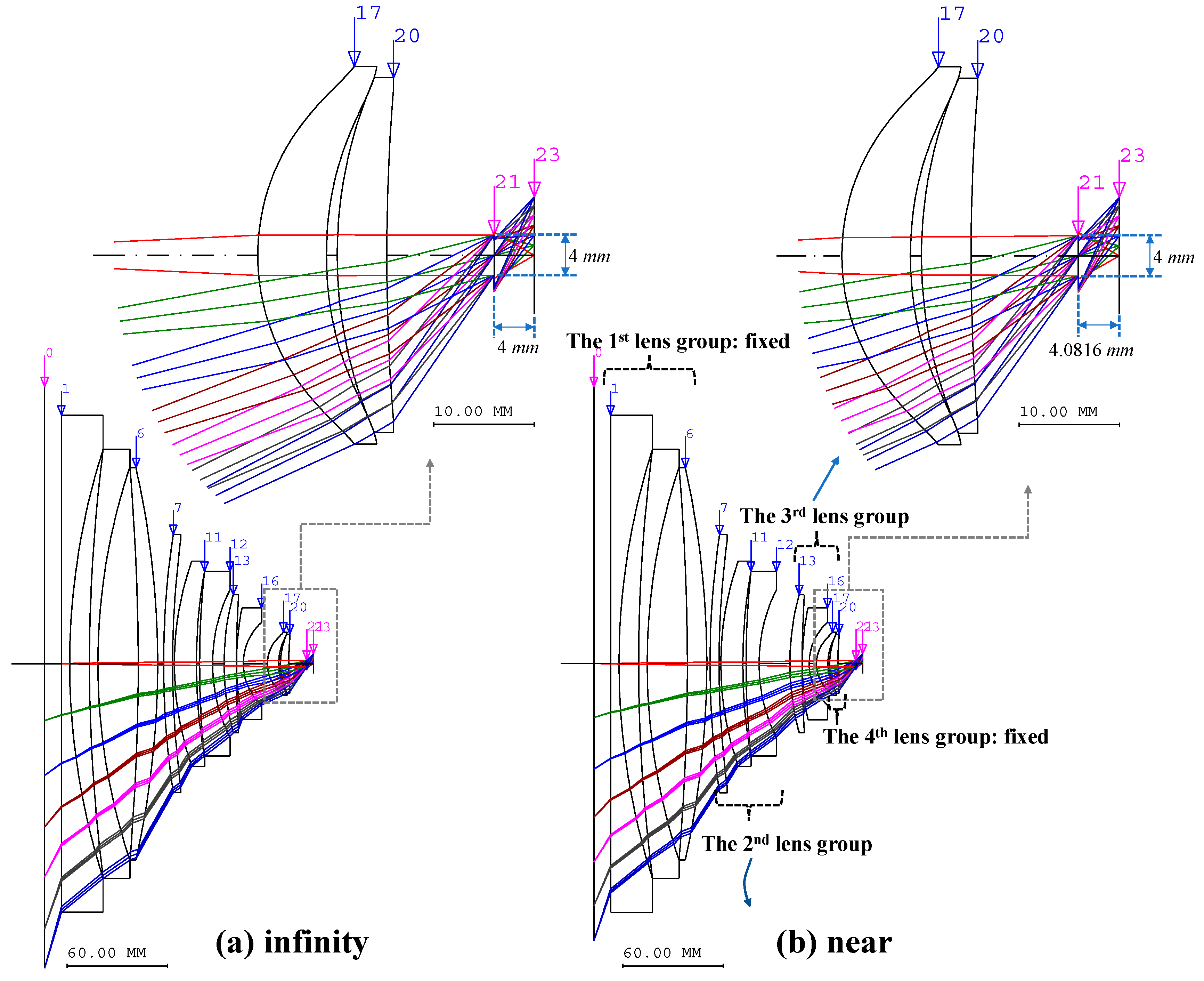
From the paraxial design shown in Figure 2, we can design the system by adding one lens each to obtain the desired performance. For optical simulation, Code V software tool was used (Synopsys, Santa Clara, CA, USA). In this process, an equivalent lens design method was used [41,42]. Conversion equivalent lenses is a method that can be applied to various optical systems in addition to the optical systems proposed in this paper [43]. In addition, there are other ways to design a real optical system from the paraxial design. Therefore, it is technically possible to design an optical system with the desired specifications and performances under the conditions shown in Figure 2. However, according to Figure 3, it can be seen that the second and third lens groups overlap. Because this cannot occur physically, an additional gap between the second and third lens groups must be secured at the design stage. Figure 3 shows the final optical layout designed by applying the equivalent lens design method from the optical system shown in Figure 2. The optical layout on the left of Figure 2 and Figure 3 are shown when the inspection distance of the test lens is infinite, and the optical layout on the right is shown when the inspection distance is 200 mm. In Figure 2 and Figure 3, the test lens is represented as a thin lens without aberration and a focal length of 4 mm. When the inspection distance is infinite, the distance from the test lens to the image surface is 4 mm. If the inspection distance is 200 mm, the distance from the test lens to the image surface is about 4.082 mm, and this value can be calculated by Equation (2). From Figure 2 and Figure 3, we observe that the distance from the test lens to the image surface is the same, and the characteristics of the paraxial design as shown in Figure 2 and the final design in Figure 3 are maintained. Our final designed collimator can change the virtual image distance from infinity to 20 cm. The inspectable field of view and diameter of aperture are 90 degrees and 4 mm, respectively.
3. Results and Discussion
The distortion of the designed optical system, as shown in Figure 4, is illustrated in Figure 3. The lens group is changed by the cam, which is the component that changes the rotational motion into linear motion [44,45]. The angle at which the cam is rotated can be changed according to the mechanical design [46,47,48]. Therefore, in this study, the value obtained by normalizing the maximum rotation cam angle to 1 is referred to as the normalized cam angle. In Figure 4, a normalized zero cam angle indicates that the virtual image is created at an infinite distance by the collimator, and one cam angle means that the virtual image is made at a distance of 200 mm from the front of the test lens. Figure 4 shows the appearance of the rectangular grid in an optical system combined with a collimator and a test lens.
In the optical design stage, the focal length of the test lens was 4 mm, and the image height was assumed to be 5.8 mm. Because the optical system distortion changes, the entire optical system magnification changes from −0.0293 to −0.0308. Therefore, although the target size must be changed according to the inspection distance, the target size must be fixed [49]. Depending on the magnification and distortion of the optical system, the target size can be calculated using Equation (5) [50,51]. As shown in Figure 3, the distortion D can be calculated as Equation (5), yp is the height calculated by finite ray tracing, and y0 is the height by paraxial ray tracing.
Here, if the target size is y and the magnification is m, y0, the height of the chief ray at the image surface, becomes yp = m·y. Therefore, Equation (5) can be converted to be Equation (6). In addition, assuming that the magnification of the optical system is −0.03, and the distortion is approximately +10%, the target size is 174 mm.
Figure 5 shows the field MTF and the longitudinal aberration. Figure 5a,b describe the field MTF and longitudinal aberration when the inspection distance of the mobile phone lens is infinite, Figure 5c,d describe the field MTF and longitudinal aberration when the inspection distance is 396 mm, and Figure 5e,f when the inspection distance is 200 mm. The MTF decreases from the center of the screen to the edge, however, there is no problem when inspecting the phone lens. As shown in the longitudinal aberration in Figure 5, the field curvature is within ±5 μm, so the optical system aberration has been sufficiently corrected.
To manufacture the optical system, as shown in Figure 3, we need to know the locus of all lens groups. Equations (1) and (3) must be used to determine the locus. All lens group locus can be obtained by combining Equations (1) and (3). Here, the unknowns are z1, z2, z3, z4, Δz, and m. However, it was previously assumed that the overall magnification m of the optical system was fixed, but m was not fixed when the actual design was applied. This is because the entire optical system distortion remains as the lens group moves [21]. It is extremely difficult to correct the optical system distortion that is not asymmetric around the aperture, as in the collimator system proposed in [20]. However, it is not necessary to determine the overall magnification of the optical system. Therefore, only Equations (1) and (3) need to be solved in parallel. Because there is a total of four unknowns, additional conditions are required [52,53]. In this case, a spline interpolation is conducted on the locus of all lens groups, and the amount of movement of a specific lens group that satisfies the desired value of the image distance of the optical system is obtained [54]. In addition, the movement amount of the lens group can be calculated using an analytical formula with precision within the depth of focus [55]. Table 3 shows each lens group locus when using this method. In Table 3, Group 1 to Group 4 means z1 to z4 of Equation (1), respectively, and is the interval between each lens group. We observe that the distance from Group 4 to the aperture does not change. In addition, ‘Image’ in Table 3 means the distance from the test lens to the image surface.
The locus for the lens groups and the magnification of the test lens are shown in Figure 6. Table 3 lists the image distances of the optical system. Here, the value minus the focal length of the test lens is Δz. The magnification of the test lens from the virtual image distance by the collimator and Δz is shown in Equation (7). The magnification in Figure 6 is the value calculated using Equation (6) [4,56,57]. As shown in Table 3 and Figure 6, Group 1 (the first lens group) and Group 4 (the last lens group) can be fixed. Therefore, the distance from Group 4 to the aperture is designed to have a constant value, so the test lens can be measured by placing it at a constant distance from the last surface of the collimator.
The optical system used in this study did not require a tolerance analysis. This is because the number of optical systems is not large, a barrel made of metal and lens is accurately manufactured and assembled.
4. Conclusions
The collimator optical system has been widely used to reduce the space required for measuring the resolution of mobile phone cameras. Recently released mobile phone cameras have shorter shooting distances. This means that objects can be shot at a close range. When the object distance that the camera can take is extremely short and only one lens group is moved, the optical system aberrations become quite large. To solve this problem, two or more lens groups must be moved to sufficiently correct aberrations in the shortest close range. Therefore, the optical system must be configured as a floating type.
The collimator used to measure the resolution of the mobile phone camera must also be designed to change the virtual image distance to the target. For this, some of the lenses that make up the collimator must move. In addition, the field angle of mobile phone cameras has gradually widened. It is therefore necessary to minimize the resolution change of the collimator according to the lens group movement. Thus, in this study, a collimator was designed as a floating type that moves two lens groups. Our designed collimator can change the virtual image distance from infinity to 200 mm. Because the MTF of the collimator did not change significantly according to the virtual image distance, it was possible to measure the resolution at the desired inspection distance of the mobile phone camera. Distortion varies from +9.33% to +13.94%, which is a large value compared to that of general optical systems. This is because the designed collimator is about to stop, and the structure is asymmetric. Considering the distortion of the collimator, the diagonal size of the target should be 174 mm. Then, the amount of movement of each lens group required to fabricate the optical system was calculated. Therefore, our proposed collimator optical system is designed as a floating type to inspect the mobile phone camera resolution from infinity to close ranges.
Author Contributions
Conceptualization, S.C., J.R. and H.C.; methodology, S.C., J.R. and H.C.; writing—original draft preparation, S.C., J.R. and H.C. All authors have read and approved of the published version of the manuscript.
Funding
This work was supported by the National Research Foundation of Korea (NRF) grant funded by the Korea government (MSIT) (No. 2020R1A2C4001606). This research was also supported by Basic Science Research Program through the National Research Foundation of Korea (NRF) funded by the Ministry of Education (NRF-2020R1I1A3052712) and the MSIT (Ministry of Science and ICT), Korea, under the Grand Information Technology Research Center support program (IITP-2021-2020-0-01612) and supervised by the IITP (Institute for Information & communications Technology Planning & Evaluation). This work (Grants No. S2563336) was supported by Business for Cooperative R&D between Industry, Academy, and Research Institute funded Korea Small and Medium Business Administration in 2019.
Institutional Review Board Statement
Not applicable.
Informed Consent Statement
Not applicable.
Data Availability Statement
The data presented in this study are included within the article.
Conflicts of Interest
The authors declare no conflict of interest.
Appendix A. Description for MATLAB Code
| Algorithm A1. Algorithm for Programming |
| 1: z0_inf=-15; z1_inf=85; z2_inf=2; z3_inf=10; z4_inf=20; z5_inf=4; |
| 2: z0_near= z0_inf; z1_near=80; z2_near=15; z3_near=z1_inf+z2_inf+z3_inf-(z1_near+z2_near); z4_near=z4_inf; z5_near=4+4^2/(200-4); |
| 3: syms k1 k2 k3 k4 |
| 4: eq1=GaussianBracket([-z0_inf, k1, -z1_inf, k2, -z2_inf, k3, -z3_inf, k4,-z4_inf, k5,-z5_inf]) ==0; |
| 5: eq2=GaussianBracket([-z0_inf, k1, -z1_inf, k2, -z2_inf, k3, -z3_inf, k4,-z4_inf, k5]) ==-1/0.03; |
| 6: eq3=GaussianBracket([-z0_near, k1, -z1_near, k2, -z2_near, k3, - z3_near, k4,-z4_near, k5, -z5_near]) ==0; |
| 7: eq4=GaussianBracket([-z0_near, k1, -z1_near, k2, -z2_near, k3, - z3_near, k4,-z4_near, k5]) ==-1/0.03; |
| 8: S=vpasolve([eq1 eq2 eq3 eq4], [k1 k2 k3 k4]) |
| 9: for i=1:1:length (S,k1) |
| 10: fprint(‘…………………………….%dWn’, i) |
| 11: fprint(‘f1(%d)=%15.8fWn’,i,1/eval(S.k1(i))) |
| 12: fprint(‘f2(%d)=%15.8fWn’,i,1/eval(S.k2(i))) |
| 13: fprint(‘f3(%d)=%15.8fWn’,i,1/eval(S.k3(i))) |
| 14: fprint(‘f4(%d)=%15.8fWn’,i,1/eval(S.k4(i))) |
| 15: end |
References
- Kim, H.-T.; Kang, S.-B.; Kang, H.-S.; Cho, Y.-J.; Kim, J.-O. Optical distance control for a multi focus image in camera phone module assembly. Int. J. Precis. Eng. Manuf. 2011, 12, 805–811. [Google Scholar] [CrossRef]
- ISO 15529:2010. ISO, Optics and Photonics—Optical Transfer Function—Principles of Measurement of Modulation Transfer Function (MTF) of Sampled Imaging System. Available online: https://www.iso.org/standard/56069.html (accessed on 2 July 2021).
- Mahajan, V.N. Optical Imaging and Aberrations: Part I: Ray Geometrical Optics; SPIE Press: Bellingham, WA, USA, 1998. [Google Scholar]
- Zappe, H. Fundamentals of Micro-Optics; Cambridge University Press: Cambridge, UK, 2010. [Google Scholar]
- ISO 12233:2017. ISO, Photography—Electronic Still Picture Imaging—Resolution and Spatial Frequency Responses. Available online: https://www.iso.org/standard/71696.html (accessed on 2 July 2021).
- Oh, N.H. Tele-Convertor Lens System and Apparatus for Evaluating Resolution Using the Same. KR Patent No. 10-1776707 B1, 4 September 2017. [Google Scholar]
- Canon Global. Canon Technology. Available online: https://global.canon/en/technology/rf-2020.html (accessed on 25 June 2021).
- Osten, W. Optical Inspection of Microsystems; CRC Press: Boca Raton, FL, USA, 2019. [Google Scholar]
- Klingshirn, C.F. Semiconductor Optics; Springer Science & Business Media: Berlin, Germany, 2012. [Google Scholar]
- Pitte, E.; Petit, V.; Lecoq, P. Optical Device, Optical Test Bench and Optical Test Method. U.S. Patent No. 9,719,882B2, 1 August 2017. [Google Scholar]
- Park, H.-J.; Lee, S.-W.; Kang, G.-M.; Moon, H.-G. Automatic Inspection System for Camera Lenses and Method thereof Using a Line Charge Coupled Device. U.S. Patent Application No. 5,726,746A, 10 March 1998. [Google Scholar]
- Rhu, J.-H.; Lee, Y.-H. Measuring Method of Optics Ability and Apparatus Thereof. KR Patent No. 10-0243171B1, 2 March 2000. [Google Scholar]
- Ken, U. Method and Apparatus for Measuring Diopter of Viewing Lens. JP Patent No. 9-243514A, 19 September 1997. [Google Scholar]
- Zawawi, R.B.A.; Choi, H.; Kim, J. High-PSRR Wide-Range Supply-Independent CMOS Voltage Reference for Retinal Prosthetic Systems. Electronics 2020, 9, 2028. [Google Scholar] [CrossRef]
- Choi, H.; Kim, S.; Kim, J.; Ryu, J.-M. Development of an Omnidirectional Optical System Based Photoacoustic Instrumentation. J. Med. Imaging Health Inf. 2018, 8, 20–27. [Google Scholar] [CrossRef]
- Murata, Y. Eccentricity Measuring Method and Eccentricity Measuring Apparatus. U.S. Patent Application No. 7,307,708B2, 11 December 2007. [Google Scholar]
- Wu, C.-L.; Angot, L.; Luo, A.-C. Optical Inspection System and Optical Inspection Method thereof. U.S. Patent Application No. 2017/0177964A1, 22 June 2017. [Google Scholar]
- Takeshi, T.; Nobuhiro, M. Auto-Collimator Device. JP Patent No. 6-273267A, 30 September 1994. [Google Scholar]
- Bass, M.; Van Stryland, E.W.; Williams, D.R.; Wolfe, W.L. Handbook of Optics; McGraw-Hill Education: New York, NY, USA, 2001. [Google Scholar]
- Sharma, K.K. Optics: Principles and Applications; Academic Press: Cambridge, MA, USA, 2006. [Google Scholar]
- Ray, S. Applied Photographic Optics; Routledge: Oxfordshire, UK, 2002. [Google Scholar]
- Hiromitsu, M. Optical Pickup, Optical Information Reproducing Device and Optically Recorded Information Reproducing Device. JP Patent No. 2010-211842A, 24 September 2010. [Google Scholar]
- Lee, C.-W. Lens Device with Constant Magnification and Variable Focal Length, and Optical Pickup Device Using It. JP Patent No. 10-186224A, 14 July 1998. [Google Scholar]
- Mouroulis, P.; Macdonald, J. Geometrical Optics and Optical Design; Oxford University Press: New York, NY, USA, 1997. [Google Scholar]
- Iga, K.; Kokubun, Y. Encyclopedic Handbook of Integrated Optics; CRC Press: Boca Raton, FL, USA, 2005. [Google Scholar]
- Ryu, J.M.; Kim, Y.S.; Jo, J.H.; Kang, G.M.; Lee, H.J.; Lee, H.K. Statistical Analysis of Focus Adjustment Method for a Floating Imaging System with Symmetric Error Factors. Korean J. Opt. Photon. 2012, 23, 189–196. [Google Scholar] [CrossRef] [Green Version]
- Gross, H.; Blechinger, F.; Achtner, B. Handbook of Optical Systems; Wily-VCH Verlag GmbH & Co: Hoboken, NJ, USA, 2005. [Google Scholar]
- Choi, H.; Choe, S.-W.; Ryu, J.-M. A Macro Lens-Based Optical System Design for Phototherapeutic Instrumentation. Sensors 2019, 19, 5427. [Google Scholar] [CrossRef] [PubMed] [Green Version]
- Ko, J.H. Converter Lens System. KR Patent No. 10-1862451, 23 May 2018. [Google Scholar]
- Ullah, M.; Pratiwi, E.; Park, J.; Lee, K.; Choi, H.; Yeom, J. Wavelength discrimination (WLD) TOF-PET detector with DOI information. Phys. Med. Biol. 2019, 65, 055003. [Google Scholar] [CrossRef]
- Ullah, M.N.; Park, C.; Pratiwi, E.; Kim, C.; Choi, H.; Yeom, J.-Y. A new positron-gamma discriminating phoswich detector based on wavelength discrimination (WLD). Nucl. Instrum. Methods Phys. Res. Sect. A 2019, 946, 162631. [Google Scholar] [CrossRef]
- Seo, S.H.; Ryu, J.M.; Choi, H. Focus-Adjustable Head Mounted Display with Off-Axis System. Appl. Sci. 2020, 10, 7931. [Google Scholar] [CrossRef]
- Choi, H.; Ryu, J.-M. Photo-Acoustic Applications Using a Highly Focused Macro Lens. J. Med. Imaging Health Inf. 2017, 7, 25–29. [Google Scholar] [CrossRef]
- Choe, S.-W.; Park, K.; Park, C.; Ryu, J.; Choi, H. Combinational light emitting diode-high frequency focused ultrasound treatment for HeLa cell. Comput. Assist. Surg. 2017, 22, 79–85. [Google Scholar] [CrossRef] [Green Version]
- Jung, J. Paraxial Design and Locus Analysis of Zoom Lens System. Ph. D. Thesis, Kyungnam University, Changwon, Korea, 1994. [Google Scholar]
- Choi, H.; Ryu, J.; Yoon, C. Development of novel adjustable focus head mount display for concurrent image-guided treatment applications. Comput. Assisted Surg. 2017, 22, 163–169. [Google Scholar] [CrossRef]
- Pedrotti, F.L.; Pedrotti, L.S. Introduction to Optics; Prentice-Hall Englewood Cliffs: Hoboken, NJ, USA, 1993; Volume 2. [Google Scholar]
- Choi, H.; Ryu, J.; Yeom, J.-Y. A Cost-effective Light Emitting Diode-acoustic System for Preclinical Ocular Applications. Curr. Opt. Photonics 2018, 2, 59–68. [Google Scholar]
- Choi, H.; Ryu, J.M.; Kim, J.H. Tolerance Analysis of Focus-adjustable Head-mounted Displays. Curr. Op. Photon 2017, 1, 474–490. [Google Scholar]
- Choi, H.; Yeom, J.-Y.; Ryu, J.-M. Development of a Multiwavelength Visible-Range-Supported Opto–Ultrasound Instrument Using a Light-Emitting Diode and Ultrasound Transducer. Sensors 2018, 18, 3324. [Google Scholar] [CrossRef] [PubMed] [Green Version]
- Lee, J.U. A Study for an Analytic Conversion between Equivalent Lenses. Korean J. Opt. Photon. 2012, 23, 17–22. [Google Scholar] [CrossRef] [Green Version]
- Choi, H.; Ryu, J.; Kim, J. A Novel Fisheye-Lens-Based Photoacoustic System. Sensors 2016, 16, 2185. [Google Scholar] [CrossRef] [PubMed]
- Ryu, J.M.; Gang, G.M.; Lee, H.K.; Lee, K.W.; Heu, M.; Jo, J.H. Optical Design and Fabrication of a Large Telephoto Zoom Lens with Fixed f/2.8 and Light Autofocus Lens. J. Opt. Soc. Korea 2015, 19, 629–637. [Google Scholar] [CrossRef] [Green Version]
- Choi, H.; Jo, J.-Y.; Ryu, J.-M. A Novel Focal Length Measurement Method for Center-Obstructed Omni-Directional Reflective Optical Systems. Appl. Sci. 2019, 9, 2350. [Google Scholar] [CrossRef] [Green Version]
- Choi, H.; Jo, J.; Ryu, J.-M.; Yeom, J.-Y. Ultrawide-angle optical system design for light-emitting-diode-based ophthalmology and dermatology applications. Technol. Health Care 2019, 27, 133–142. [Google Scholar] [CrossRef] [Green Version]
- Choi, H.; Ryu, J.-M.; Yeom, J.-Y. Development of a Double-Gauss Lens Based Setup for Optoacoustic Applications. Sensors 2017, 17, 496. [Google Scholar] [CrossRef] [PubMed] [Green Version]
- Choi, H.; Ju, Y.J.; Jo, J.H.; Ryu, J.-M. Chromatic aberration free reflective mirror-based optical system design for multispectral photoacoustic instruments. Technol. Health Care 2019, 27, 397–406. [Google Scholar] [CrossRef] [Green Version]
- Ullah, M.N.; Park, Y.; Kim, G.B.; Kim, C.; Park, C.; Choi, H.; Yeom, J.-Y. Simultaneous Acquisition of Ultrasound and Gamma Signals with a Single-Channel Readout. Sensors 2021, 21, 1048. [Google Scholar] [CrossRef] [PubMed]
- Kim, J.; Kim, K.S.; Choi, H. Development of a low-cost six-axis alignment instrument for flexible 2D and 3D ultrasonic probes. Technol. Health Care 2021, 29, 77–84. [Google Scholar] [CrossRef] [PubMed]
- Choi, H.; Ryu, J. Design of Wide Angle and Large Aperture Optical System with Inner Focus for Compact System Camera Applications. Appl. Sci. 2019, 10, 179. [Google Scholar] [CrossRef] [Green Version]
- Choi, H.; Choe, S.-w.; Ryu, J. Optical Design of a Novel Collimator System with a Variable Virtual-Object Distance for an Inspection Instrument of Mobile Phone Camera Optics. Appl. Sci. 2021, 11, 3350. [Google Scholar] [CrossRef]
- Choi, H.; Park, J.; Lim, W.; Yang, Y.-M. Active-beacon-based driver sound separation system for autonomous vehicle applications. Appl. Acoust. 2021, 171, 107549. [Google Scholar] [CrossRef]
- Shin, S.-H.; Yoo, W.-S.; Choi, H. Development of Public Key Cryptographic Algorithm Using Matrix Pattern for Tele-Ultrasound Applications. Mathematics 2019, 7, 752. [Google Scholar] [CrossRef] [Green Version]
- Chaves, J. Introduction to Nonimaging Optics; CRC press: Boca Raton, FL, USA, 2008. [Google Scholar]
- Kim, K.M.; Choe, S.-H.; Ryu, J.-M.; Choi, H. Computation of Analytical Zoom Locus Using Padé Approximation. Mathematics 2020, 8, 581. [Google Scholar] [CrossRef] [Green Version]
- Yamaji, K. Progress in Optics; Elsevier: Amsterdam, The Netherlands, 1967. [Google Scholar]
- Choi, H.; Ryu, J.-M.; Choe, S.-W. A novel therapeutic instrument using an ultrasound-light-emitting diode with an adjustable telephoto lens for suppression of tumor cell proliferation. Measurement 2019, 147, 106865. [Google Scholar] [CrossRef]
Figure 1.
Layout of inspection instrument of mobile phone camera optics.

Figure 2.
Paraxial optical layout for the third solution.

Figure 3.
Optical layout for the final design.

Figure 4.
Distortion graphs for the final collimator design.

Figure 5.
(a) The field MTF and (b) longitudinal aberration when the inspection distance of the mobile phone lens is infinite. (c) The field MTF and (d) longitudinal aberration when the inspection distance is 396 mm. (e) The field MTF and (f) longitudinal aberration when the inspection distance is 200 mm.

Figure 6.
Locus (left) and magnification (right) for our designed final collimator system.


Table 1.
The initial distance between lens groups.
| Distance | z0 | z1 | z2 | z3 | z4 | Δz | m |
|---|---|---|---|---|---|---|---|
| Infinity | 5 mm | 85 mm | 2 mm | 10 mm | 20 mm | 0 mm | −0.03 |
| Near | 5 mm | 80 mm | 15 mm | 2 mm | 20 mm | 0.0816 mm | −0.03 |
Table 2.
The solutions for Equations (3) and (4).
| Solution 1 | Solution 2 | Solution 3 | Solution 4 | |
|---|---|---|---|---|
| f1 = 1/k1 | −3.230 mm | 4.670 mm | −6663.425 mm | 4.705 mm |
| f2 = 1/k2 | 28.040 mm | 0.094 mm | −92.489 mm | 0 mm |
| f3 = 1/k3 | 87.941 mm | −22.961 mm | −48.026 mm | 1.663 mm |
| f4 = 1/k4 | −17.202 mm | 11.759 mm | 33.909 mm | 0.129 mm |
Table 3.
Locus table for our designed final collimator system.
| Cam Angle | Object | Group 1 | Group 2 | Group 3 | Group 4 | Image | Δz | Mag. |
|---|---|---|---|---|---|---|---|---|
| 0 (infinity) | 10 | 3.592 | 6.821 | 14.331 | 10.666 | 4 | 0 | 0 |
| 0.1 | 10 | 3.614 | 7.912 | 13.218 | 10.666 | 4.008 | 0.008 | −0.002 |
| 0.3 | 10 | 3.657 | 9.994 | 11.093 | 10.666 | 4.024 | 0.024 | −0.006 |
| 0.5 | 10 | 3.508 | 12.160 | 9.076 | 10.666 | 4.040 | 0.040 | −0.010 |
| 0.7 | 10 | 3.089 | 14.509 | 7.146 | 10.666 | 4.057 | 0.057 | −0.014 |
| 1.0 (near) | 10 | 1.914 | 18.435 | 4.395 | 10.666 | 4.081 | 0.081 | −0.020 |
Publisher’s Note: MDPI stays neutral with regard to jurisdictional claims in published maps and institutional affiliations. |
© 2021 by the authors. Licensee MDPI, Basel, Switzerland. This article is an open access article distributed under the terms and conditions of the Creative Commons Attribution (CC BY) license (https://creativecommons.org/licenses/by/4.0/).
Share and Cite
MDPI and ACS Style
Chee, S.; Ryu, J.; Choi, H. New Optical Design Method of Floating Type Collimator for Microscopic Camera Inspection. Appl. Sci. 2021, 11, 6203. https://0-doi-org.brum.beds.ac.uk/10.3390/app11136203
AMA Style
Chee S, Ryu J, Choi H. New Optical Design Method of Floating Type Collimator for Microscopic Camera Inspection. Applied Sciences. 2021; 11(13):6203. https://0-doi-org.brum.beds.ac.uk/10.3390/app11136203
Chicago/Turabian StyleChee, Seonkoo, Jaemyung Ryu, and Hojong Choi. 2021. "New Optical Design Method of Floating Type Collimator for Microscopic Camera Inspection" Applied Sciences 11, no. 13: 6203. https://0-doi-org.brum.beds.ac.uk/10.3390/app11136203
Note that from the first issue of 2016, this journal uses article numbers instead of page numbers. See further details here.