Article

Low-Voltage Ride-Through of the Novel Voltage Source-Controlled PMSG-Based Wind Turbine Based on Switching the Virtual Resistor

School of Electrical Engineering, Nantong University, Nantong 226019, China
*
Authors to whom correspondence should be addressed.
Submission received: 28 May 2021 / Revised: 23 June 2021 / Accepted: 30 June 2021 / Published: 4 July 2021
(This article belongs to the Special Issue Boosting Wind Power Integration)

Abstract

:
Voltage source (VS) control based on inertia synchronization is a novel phase lock loop (PLL)-less autonomous grid-synchronization control strategy suitable for the permanent magnet synchronous generator (PMSG)-based wind turbine. It can autonomously sense grid frequency fluctuations by adopting the dynamics of DC-link capacitor, and it has the advantage of stable operation in an extremely weak grid. This paper further studies the low-voltage ride-through (LVRT) of the PMSG-based wind turbine under the VS control, and presents a wind turbine structure with the additional energy storage battery on the DC side, which not only improves its LVRT capability but also enables the wind turbine to participate in the grid primary frequency regulation. The transient characteristics of VS-controlled wind turbines after the occurrence of the short-circuit fault are analyzed, and a current suppression strategy via switching the virtual resistor in the control loop of the grid-side converter (GCS) is presented. Through coordination with the energy storage battery, the LVRT of the PMSG-based wind turbine is realized, which has the advantage of withstanding a long-time short-circuit fault. Finally, based on the PSCAD/EMTDC simulation platform, the feasibility of the control strategy and the correctness of the theoretical analysis are verified.

1. Introduction

As clean and renewable energy, wind power has broad application prospects, and will become more important in the future energy consumption pattern [1,2,3,4]. Since wind turbines cannot provide short-circuit current as conventional synchronous generators do, with the increasing penetration of wind power integrated to the grid [5,6], the equivalent strength of the grid reduces gradually, and the grid tends to become a weak grid [7,8]. The characteristics of the weak grid are mainly reflected in the following two aspects [9]: (i) in the electromechanical perspective, the grid lacks rotating masses, causing frequency instability with the high-penetration integration of wind power [10]; (ii) in the electrical perspective, the poor voltage-supporting capability of the grid will lead to abnormal interactions between wind turbines and the grid, such as the low-frequency oscillation, sub-synchronous oscillation, and harmonic oscillation, which endangers the safe and stable operation of the grid [11]. In order to cope with the high-penetration integration of large-scale wind power, the following three challenges need to be overcome: (1) wind turbines participate in the grid regulation, i.e., inertial response and primary frequency regulation; (2) the stable operation of wind turbines under weak grid conditions; (3) the LVRT of wind turbines when the short-circuit fault occurs [12].
The control of wind power converters is the key to influence the grid-connected performance of wind turbines. At present, the conventional control strategy of wind power converters adopts the PLL to orientate with the grid, and realizes power regulation by adjusting the injected current. The conventional converter control strategy makes the converter exhibit the current source characteristics [13], thus it is called the current source (CS) control. Under the CS control, since wind turbines act as constant power sources and have no responses to frequency fluctuations from the grid, the integration of high-penetration wind power reduces the equivalent inertia of the grid, which is not conducive to the frequency stability of the power system [14]. On the other hand, when designing the current control loop of a wind power converter, the influence of the grid impedance is usually ignored. However, the effective bandwidth of the current loop decreases with the increase of the grid impedance, causing abnormal interactions between the PLL and the current control loop, which will lead to oscillations and instability [15]. Although introducing the auxiliary control loop to the existing CS control structure can simulate the inertial response function and suppress oscillations of wind turbines, this kind of control strategy exhibits poor adaptability in practical applications [16].
By simulating the dynamic equation of the synchronous generator (SG), the VS control directly controls the amplitude and phase of the converter’s output voltage, and has the function of PLL-less autonomous grid-synchronization. In addition, the VS control can be viewed as a grid-forming control strategy [17]. At present, the existing virtual synchronous generator (VSG) control method [18] and power synchronization control method [19] that imitate the motion equation of the synchronous generator can be regarded as the VS control. These two VS control methods, setting the output power as the control target, are suitable for converters with stable and controllable input power, but have limitations in the application to PMSG-based wind turbines with intermittent and fluctuating input of wind power. The author proposes a novel VS control strategy by employing the inherent dynamics of the GSC’s DC-link capacitor to automatically synchronize the grid in [20]. Moreover, the functions of autonomous inertial response and stable operation under weak grid conditions are achieved at the same time. However, this paper [20] does not study the primary frequency regulation and LVRT of the PMSG-based wind turbine.
When low-voltage fault occurs in the grid, the PMSG-based wind turbine cannot transmit active power to the grid effectively, which increases the DC-link voltage and causes damage to the wind turbine [21]. In order to suppress the DC-link overvoltage, a chopper [22] or crowbar [23] can be connected in the DC side of the PMSG-based wind turbine, and the excessive power can be consumed by the passive resistor. It is also feasible to add the energy storage device to the DC side [24,25], which can absorb the excessive energy and maintain the DC-link voltage within the feasible range. In addition, [26] points out that the abrupt change of the grid voltage during the short-circuit fault will also cause frequency instability and endanger the synchronization of wind turbines. These above-mentioned studies [21,22,23,24,25,26] on the LVRT are carried out with the wind turbine under the conventional CS control, whereas the short-circuit characteristics of the VS-controlled wind turbine [20] are unknown. Therefore, it is urgent to study the short-circuit characteristics of wind turbines under the VS control and present the corresponding LVRT control strategy.
With respect to the PMSG-based wind turbine under the VS control strategy proposed in [20], this paper adds energy storage batteries on the DC side to realize the functions of primary frequency regulation and LVRT, and the corresponding control strategies are presented at the same time. The overcurrent can be suppressed by switching in the virtual resistor in the control loop of GSC during the grid fault. On the basis of analyzing the dynamic characteristics of the VS-controlled wind turbine when the short-circuit fault occurs, this paper proposes a design method of the virtual resistor parameter. At last, based on the PSCAD/EMTDC simulation platform, the feasibility of the control strategy and the correctness of the theoretical analysis are verified.
The remainder of this paper is organized as follows. Section 2 introduces the kinetic similarity between the SG and the GSC. Section 3 presents the control structure of the VS-controlled wind turbine with the additional energy storage. Section 4 analyzes the transient current characteristics of the VS-controlled wind turbines after short-circuit fault. Section 5 proposes a design method of the virtual resistor parameter. Section 6 provides simulations based on PSCAD/EMTDC. Section 7 concludes this paper.

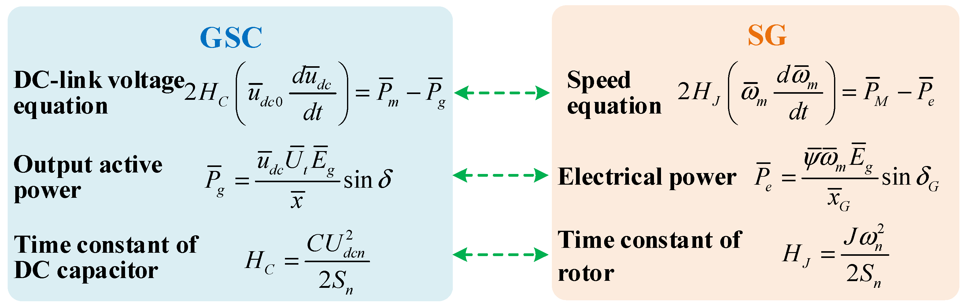
2. Kinetic Similarity between SG and GSC

Through comparison, it can be seen that the GSC of the PMSG-based wind turbine and the SG have similar dynamic equations, as shown in Figure 1, where the symbols with superscripts in equations are represented in per-unit value, HC is the inertia constant of the DC-link capacitor, u ¯ d c 0 is the steady-state DC-link voltage, u ¯ d c is the DC-link voltage, P ¯ m is the output power of the machine side converter (MSC), P ¯ g is the output power of the GSC, U ¯ t is the modulation voltage amplitude of the GSC, E ¯ g is the grid voltage amplitude, x ¯ is the grid reactor, δ is the phase difference between the GSC’s output voltage and the grid voltage, C is the DC-link capacitance, Udcn is the rated DC-link voltage, Sn is the rated capacity of the wind turbine, HJ is the inertia constant of the SG’s rotor, ω ¯ m is the speed of the SG, P ¯ M is the input power of the SG, P ¯ e is the electrical power of the SG, ψ ¯ is the magnetic linkage of the SG, x ¯ G is the equivalent reactance, and δ G is the power angle of the SG.
In Figure 1, the DC-link voltage of the GSC has a similar dynamic equation with the rotated speed of the SG. In the same way, the modulation voltage amplitude of the GSC shows similar dynamics compared with the magnetic linkage of the SG. Similarly, the inertia constant, HC, of the capacitor also exhibits similar dynamic characteristics to the inertia constant, HJ, of the SG’s rotor. These above similarity relationships between the GSC and the SG are shown in Figure 2. It should be noted that these physical quantities in Figure 2 have similar dynamic characteristics, but they are not equal.

3. System Control Structure

According to the kinetic similarity relationships between the GSC and the SG, as shown in Figure 2, the control structure of the PMSG-based wind turbine with additional energy storage is designed in Figure 3. This paper is based on our previous work [20], and more detailed descriptions about the control structure of the VS-controlled wind turbine can be referred to in [20]. The GSC realizes the autonomous grid synchronization based on the dynamics of the DC-link capacitor. When the short-circuit fault occurs in the grid, the virtual resistor control is added to the GSC’s control loop to suppress the overcurrent. The MSC still adopts the vector control method based on the orientation of the rotor flux linkage. The auxiliary energy storage device realizes the function of primary frequency regulation. In addition, the energy storage device can also maintain the DC-link voltage within the feasible range.

3.1. Control Strategy of the GSC

Since the DC-link voltage, u ¯ d c , of the GSC can be compared to the magnetic linkage, ψ ¯ , of the SG, the authors establish the relationship between the angular frequency, ω ¯ G S C , of the GSC’s output voltage and the DC-link voltage, u ¯ d c , i.e., making ω ¯ G S C equal to u ¯ d c . In the control loop of the GSC in Figure 3, the DC-link voltage, u ¯ d c , passes through an integrator, and the output is the phase θ of the GSC’s output voltage. The output reactive power can be controlled by adjusting the amplitude, Ut, of the GSC’s output AC voltage. The modulation voltage signal, utabc, of the GSC is generated according to Ut and θ.
The fault detector estimates the grid state and generates a fault flag according to the AC side’s voltage and current of the wind turbine. When the short-circuit fault occurs, the fault flag is 1, otherwise the flag is 0. In order to suppress the overcurrent during the grid failure, the virtual resistor, Rv, is added to the GSC’s control loop. The virtual resistor, Rv, is cut out from the control loop after the fault is cleared. Corresponding to Figure 3, the switch SG is closed when the fault flag is 1. The switch SG is open and the virtual resistor, Rv, is cut out when the fault flag is 0.

3.2. Control Strategy of the MSC

The MSC still adopts the vector control method based on the orientation of the rotor flux linkage. In the control loop of the MSC in Figure 3, the cascaded control structure, including the outer power loop and the inner current loop, is employed. Since the DC-link voltage can reflect the dynamics of the grid frequency, an auxiliary control loop based on the differential of the DC-link voltage is introduced to the power reference of the MSC, which can realize the autonomous inertial response function of the wind turbine to the grid. When a short-circuit fault occurs in the grid, i.e., the flag is 1, the output of the switch SM is the limited power reference, Pmflt, aiming to reduce the output power of the MSC. When the short-circuit fault is cleared, i.e., the flag is 0, the output of the switch SM is the normal power reference, and the MSC returns to the normal operation state.

3.3. Control Strategy of the Energy Storage Converter

The energy storage converter (ESC) can realize the primary frequency regulation function through absorbing and releasing energy. Besides, when the short-circuit fault occurs, the ESC can also absorb the excessive power to maintain the DC-link voltage within a reasonable range, avoiding the DC-link overvoltage. In Figure 3, the topology of the ESC is a bidirectional buck/boost converter. In the control loop of the ESC, the difference between the rated DC-link voltage, udcn, and the feedback value, udc, passes through a droop controller with a droop coefficient, Kd, and its output is the current reference value of the ESC. Since the DC-link voltage of the wind turbine can reflect the dynamics of the grid frequency, the droop control can enable the ESC to automatically realize the primary frequency regulation function. Moreover, when the power level of the battery energy is too high or too low, the SOC control adjusts the setting value of the DC-link voltage, so as to move the droop characteristic curve up or down, which can realize the forced discharge or charge of the battery.
Since the droop control is the differential adjustment, the DC-link voltage cannot be controlled at the rated value, udcn. When the short-circuit fault occurs in the grid, i.e., the flag is 1, in order to avoid the DC-link overvoltage, the switch SE is closed. Therefore, the integrating regulator is put into the control loop of the ESC, which can maintain the DC-link voltage within the reasonable range. After the short-circuit fault is cleared, i.e., the flag is 0, the switch SE is closed and the integrating regulator is cut out from the control loop, which means the ESC returns to the normal operation state.

4. Transient Current Characteristics of Wind Turbines after Short-Circuit Fault

The control strategy based on switching the virtual resistor can suppress the overcurrent of the GSC when the short-circuit fault occurs. For the tuning of virtual resistor parameters, it is essential to study the transient current characteristics of the VS-controlled wind turbine during the grid short-circuit fault.
Figure 4 shows an equivalent circuit diagram of the grid-connected wind turbine system during the three-phase short-circuit fault, where the wind turbine and the grid are all represented by voltage sources, the grid voltage is eg, the AC-side voltage of the wind turbine is ug, and the ground-connection resistance at the fault point is R.
Before the three-phase short-circuit fault occurs, the switch SG in Figure 3 is opened. Correspondingly, the switch S1 is closed and the switch S2 is opened in Figure 4, which means the virtual resistor, Rv, is not introduced to the main circuit and the fault point is not grounded. When the three-phase short-circuit fault occurs, the switch S2 is closed, which means the fault point is grounded through the resistor, R. In order to suppress the overcurrent of the wind turbine, the switch SG in Figure 3 is closed. Correspondingly, the switch S1 in Figure 4 is opened and the virtual resistor, Rv, is put into the main circuit.
According to Figure 4, taking the phase A as an example, the equivalent circuit diagram of the grid-connected wind turbine system in the s domain after the three-phase short-circuit fault occurs is shown in Figure 5, where the grid voltage is EgA(s), the equivalent AC-side voltage of the wind turbine is UgA(s), the output current magnitude of the wind turbine before the short-circuit fault is Igm, the output current of the wind turbine after the short-circuit fault is I1A(s), and the grid-side current is I2A(s). The time-domain grid voltage, egA, of the phase A can be expressed as
e g A = E g m cos ( ω t + φ )
where Egm is the amplitude of the grid voltage and φ is the phase of the grid voltage.
The AC-side equivalent phase A voltage, ugA, of the wind turbine in the time domain can be expressed as
u g A = U g m cos ( ω t + θ u )
where Ugm is the amplitude of the wind turbine’s AC-side equivalent voltage, θu is the phase and θu = φ + δu, and δu is the phase difference that the voltage, ugA, leads ahead of the grid voltage, egA.
The phase A output current of the wind turbine in the time domain before the short-circuit fault is
i g A = I g m cos ( ω t + θ i )
where Igm is the amplitude of the wind turbine’s output current before the short-circuit fault, θi is the phase and θi = φ + δi, and δi is the phase difference that the output current, igA, leads ahead of the grid voltage, egA.
Assuming that the short-circuit fault occurs at the time 0, changing the grid voltage phase φ in the range of 0 to 2π corresponds to the occurrence of three-phase short-circuit fault at any time. Converting the voltages egA and ugA in (1) and (2) to the s domain, the expressions of EgA(s) and UgA(s) in Figure 5 are
E g A ( s ) = E g m s cos φ ω g sin φ s 2 + ω g 2
U g A ( s ) = U g m s cos θ u ω g sin θ u s 2 + ω g 2
where ωg is the angular frequency of the grid, i.e., 100π rad/s.
In Figure 5, the voltage equation of the current path 1 is
U g A ( s ) = R v I 1 A ( s ) + s L f I 1 A ( s ) + L f I g m cos θ i + R [ I 1 A ( s ) I 2 A ( s ) ]
In the same way, the voltage equation of the current path 2 in Figure 5 is
E g A ( s ) = R l i n e I 2 A ( s ) + L l i n e I g m cos θ i s L l i n e I 2 A ( s ) + R [ I 1 A ( s ) I 2 A ( s ) ]
Combining Equations (6) and (7), eliminating I2A(s), the output current, I1A(s), of the wind turbine after the short-circuit fault can be derived as
I 1 A ( s ) = ( R + R l i n e + s L l i n e ) R [ U g A ( s ) L f I g m cos θ i ] + L l i n e I g m cos θ i E g A ( s ) ( R + R l i n e + s L l i n e ) ( R + R v + s L l i n e ) R R
It can be seen from Equation (8) that the virtual resistance, Rv, is located in the denominator of the equation, which means that increasing the virtual resistance, Rv, can suppress the overcurrent of the wind turbine after the fault occurs. Carrying out the inverse Laplace transform of Equation (8), the phase A output current, i1A(t), of the wind turbine in the time domain after the short-circuit fault can be obtained. Since the expression of i1A(t) is extremely complicated, an actual grid-connected wind turbine system is taken as an example, where the grid-side filter inductance, Lf, is 0.038 mH, the ground-connected resistance, R, at the fault point is 0.1 Ω, the virtual resistance, Rv, is 0.3 Ω, the wind turbine operates in the state of unit power factor and the rated active power, Pg, is 2 MW, the grid voltage phase, φ, is 0, and the short-circuit ratio (SCR) of the grid is 2.5, i.e., Lline is 0.304 mH and Rline is 0.045 Ω. Substituting these above parameters into Equation (8), the output current, i1A(t), of the wind turbine after the short-circuit fault occurs is derived as
i 1 A ( t ) = 1460 cos ( 100 π t + 49.7 ) I + 1040 e 5501 t [ cosh ( 5110 t ) + 0.94 sinh ( 5110 t ) ] II
It can be seen from Equation (9) that the output current, i1A(t), after the fault can be derived into two parts, where part I is the steady-state component of the short-circuit current, and part II is the transient component of the short-circuit current. Due to the exponential decay component contained in part II, the transient component of the short-circuit current quickly decays to zero. The above analysis shows that the output current of the wind turbine quickly enters a steady state after the fault occurs, and the transition process is short.
In order to study how the timing of the fault occurrence impacts the maximum value, I1max, of the wind turbine’s output current, Figure 6 shows the curve of the maximum value, I1max, with different grid voltage phases, φ. It can be seen from Figure 6 that as the grid voltage phase, φ, varies from 0 to 2π, the value of I1max varies in the range of 1462 A to 2184 A, which indicates the maximum value of the wind turbine’s output current during the short-circuit fault is between the steady-state current before the fault and the steady-state current after the fault. Therefore, in order to limit the output overcurrent of the wind turbine after the short-circuit fault, the value of the virtual resistance, Rv, can be designed with the goal to ensure that the post-fault output steady-state current does not exceed its pre-fault value.

5. Design of the Virtual Resistor

Since the design of the virtual resistor, Rv, is related to the wind turbine’s steady-state current after the fault, and the frequency-domain expression of the short-circuit current including the steady-state component and the transient component in Equation (8) is too complicated, it is essential to calculate the steady-state expression of the wind turbine’s output current after the short-circuit fault.

5.1. Steady-State Current of the Wind Turbine after the Fault

Figure 7 shows the steady-state equivalent circuit diagram of the grid-connected wind turbine system with the virtual resistor control after a short-circuit fault in the rotating dq frame, where the d-axis of the rotating dq frame coincides with the grid voltage vector. Therefore, the grid voltage vector can be expressed as Egm, and the equivalent voltage vector of the wind turbine is Ugmcosδu + jUgmsinδu.
In Figure 7, the voltage equation of the current path 1 is
U g m cos δ u + j U g m sin δ u = ( R v + j ω g L f ) ( I 1 d + j I 1 q ) + R [ ( I 1 d I 2 d ) + j ( I 1 q I 2 q ) ]
In Figure 7, the voltage equation of the current path 2 is
E g m = ( R l i n e + j ω g L l i n e ) ( I 2 d + j I 2 q ) + R [ ( I 1 d I 2 d ) + j ( I 1 q I 2 q ) ]
According to Equations (10) and (11), the equation for I1d, I1q, I2d, and I2q can be derived as
A [ I 1 d I 1 q I 2 d I 2 q ] T = B
where
A = [ R + R v ω g L f R 0 ω g L f R + R v 0 R R 0 R R l i n e ω g L l i n e 0 R ω g L l i n e R R l i n e ]
B = [ U g m cos δ u U g m sin δ u E g m 0 ] T
According to Equation (14), the expression of the current vector, I12, is obtained as
I 12 = [ I 1 d I 1 q I 2 d I 2 q ] T = A 1 B
According to Equation (15), the amplitude, I1m, of the wind turbine’s steady-state current after the fault can be expressed as
I 1 m = I 12 ( 1 ) 2 + I 12 ( 2 ) 2

5.2. Virtual Resistance Range to Avoid Overcurrent

The value of the grounding resistance, R, affects the steady-state value of the wind turbine’s output current after a short-circuit fault. With the decrease of the grounding resistance, R, the amplitude, I1m, of the wind turbine’s steady-state current after the fault increases. When the value of R is 0, i.e., the fault point is connected to the ground directly, according to Equation (16), the amplitude, I1m, after the short-circuit fault is derived as
I 1 m = U g m R v 2 + ω g 2 L f 2 .
It can be seen from Figure 6 that the maximum value of the wind turbine’s output current during the short-circuit fault is between the steady-state current before the fault and the steady-state current after the fault. Thus, as long as the amplitude, I1m, of the steady-state current after the fault is less than or equal to the amplitude, I1nm, of the steady-state current before the fault, the output current of the wind turbine can be guaranteed not to exceed its limit. Based on this relationship, the range of the virtual resistance, Rv, is
R v ( U g m I 1 n m ) 2 ω g 2 L f 2 .
When the point of the short-circuit fault is close to the grid side, the inductance of the equivalent filter inductor, Lf, increases, and the steady-state value of the wind turbine’s output current after the short-circuit fault decreases. Therefore, the range of the virtual resistance, Rv, in Equation (18) can ensure the output current of the wind turbine does not exceed the limitation after the short-circuit fault. Equation (18) determines the lower boundary of the virtual resistance, Rv. If the value of virtual resistance, Rv, continues to increase, the corresponding amplitude of the wind turbine’s output current after the fault will decrease, whereas the energy storage device with larger capacity is required to absorb the excessive energy. Therefore, the value of the virtual resistance, Rv, cannot be too large, from the perspective of energy storage capacity.

6. Simulation Verification

In order to verify the feasibility of the control strategy and the correctness of the theoretical analysis, a simulation model of the PMSG-based wind turbine system with the auxiliary energy storage battery was built on the PSCAD/EMTDC platform. The parameters of the system are shown in Table 1 below.

6.1. Verification of the Inertial Response and Primary Frequency Regulation

Figure 8 presents simulation results of inertial response and primary frequency regulation when the grid frequency fluctuates, where the grid-side filter inductor, Lf, is 0.038 mH, the short-circuit ratio is 2.5, i.e., the line inductor, Lline, is 0.304 mH and the line resistor, Rline, is 0.045 Ω. In Figure 8, when the grid frequency rises from 1.00 p.u. to 1.01 p.u. at 40 s, the DC-link voltage, udc, follows the real-time fluctuation of the grid frequency and increases to 1.01 p.u. The MSC reduces the output power and then recovers. At the same time, the wind turbine speed rises and then recovers, realizing the inertial response function. The ESC absorbs power, realizing the primary frequency regulation function. When the grid frequency decreases from 1.00 p.u to 0.99 p.u. at 60 s, the DC-link voltage, udc, follows the real-time fluctuation of the grid frequency and decreases to 0.99 p.u. The MSC increases the output power and then recovers. At the same time, the wind turbine speed decreases and then recovers, realizing the inertial response function. The ESC releases power to realize the primary frequency regulation function.
It can be seen from Figure 8 that under the proposed VS control strategy, the DC-link voltage of the GSC can sense the fluctuation of the grid frequency in real time. In addition, according to the dynamics of the DC-link voltage, the PMSG-based wind turbine with the auxiliary energy storage battery can realize the function of inertial response and primary frequency regulation at the same time, where the inertial response function is realized relying on the inertia of the wind wheel, and the primary frequency regulation function is realized through the ESC.

6.2. Verification of the Wind Turbine’s Transient Current Characteristics

Figure 9 presents simulation results of the wind turbine’s output current with different ground-connection resistor when short-circuit fault occurs, where the virtual resistor control is not activated, the grid-side filter inductor, Lf, is 0.038 mH, the grid voltage phase, φ, is 0, the output active power of the wind turbine before short-circuit fault is 2 MW, the output reactive power is 0, and the short-circuit ratio is 2.5, i.e., the line inductor, Lline, is 0.304 mH, and the line resistor, Rline, is 0.045 Ω. In Figure 9a, the three-phase short-circuit fault occurs at 2 s, and the ground-connection resistor, R, at the fault point is 1 Ω. After the short-circuit fault, the output current of the wind turbine increases for a short instant and then enters a steady state. In Figure 9b, the three-phase short-circuit fault occurs at 2 s, and the ground-connection resistor, R, at the fault point is 0.1 Ω. After the short-circuit fault, the output current of the wind turbine increases significantly and then enters a steady state. Comparing Figure 9a with Figure 9b, it is not difficult to find that the smaller ground-connected resistor, R, corresponds to the higher steady-state value of the wind turbine’s output current after the short-circuit fault. In addition, after the short-circuit fault, the output current of the wind turbine quickly enters the steady state. The transient process during the fault is short and the short-circuit impulse current is very small. The simulation result of the wind turbine’s output current in Figure 9 is consistent with the analytical calculation result based on Equation (8), which verifies the correctness of the theoretical analysis.
Figure 10 presents simulation results of the wind turbine’s output current with different grid voltage phase, φ, when the short-circuit fault occurs, where the virtual resistor control is activated and the value of the virtual resistor, Rv, is 0.3 Ω, the grid-side filter inductor, Lf, is 0.038 mH, the ground-connection resistor, R, is 0.1 Ω, the output active power of the wind turbine before the short-circuit fault is 2 MW, the output reactive power is 0, and the short-circuit ratio is 2.5, i.e., the line inductor, Lline, is 0.304 mH, and the line resistor, Rline, is 0.045 Ω. In Figure 10a, the wind turbine’s output current quickly enters a steady state after the short-circuit fault, and the transient process is short. After the virtual resistor is put in, the amplitude of the wind turbine’s output current is smaller, indicating that the virtual resistor control can effectively suppress the wind turbine’s overcurrent after the short-circuit fault. In Figure 10b,c, where the grid voltage phases, φ, are 60° and 150°, respectively, it can be seen that the virtual resistor control can effectively suppress the wind turbine’s output current. In addition, the simulation result of the wind turbine’s output current in Figure 10 is consistent with the analytical calculation result based on Equation (8), verifying the correctness of the theoretical analysis.

6.3. Verification of the LVRT Control Strategy

Figure 11 presents simulation results of wind turbine’s LVRT based on switching the virtual resistor, where the grid-side filter inductor, Lf, is 0.038 mH, the short-circuit fault occurs at 24 s and the ground-connection resistor, R, is 0.05 Ω, the output active power of the wind turbine before short-circuit fault is 2 MW, the output reactive power is 0, the grid voltage phase, φ, is 0, and the short-circuit ratio is 2.5, i.e., the line inductor, Lline, is 0.304 mH, and the line resistor, Rline, is 0.045 Ω. According to Equation (18), the value of virtual resistance, Rv, is set to 0.3 Ω. It can be seen from Figure 11 that the amplitude of the voltage at the point of common connection (PCC) decreases after the short-circuit fault, and the short-circuit fault flag changes from 0 to 1. The ground-connection resistor, R, is 0.05 Ω, which makes the voltage at the PCC drop to 0.2 p.u. The output current, i1abc, of the wind turbine increases in a short transient and then remains at the rated value. The DC-link voltage, udc, increases briefly and then remains at the rated value. The ESC first absorbs energy and then emits energy. The MSC reduces the rated output power to 0.1 p.u. The speed of the wind wheel increases, and the pitch angle increases correspondingly.
At 26 s, the fault is cleared, and the voltage amplitude of PCC rises instantly. The short-circuit fault flag changes from 1 to 0. Since the virtual resistance, Rv, of the GSC slowly decreases to 0, the output current, i1abc, of the wind turbine is restored to the rated value gradually. The DC-link voltage fluctuates and then remains at the rated value. The output power of the MSC gradually increases from 0.1 p.u. to the rated value. The ESC first absorbs the power and then the output power becomes 0. The rotor speed gradually recovers, and the pitch angle gradually decreases to zero. In Figure 11, the wind turbine maintains operation even during a 2 s short-circuit fault, which proves the feasibility of the proposed LVRT control strategy based on switching the virtual resistor.

7. Conclusions

In this paper, the VS control of the PMSG-based wind turbine with the auxiliary energy storage battery is researched. The system structure and control strategy are presented, where the GSC adopts the dynamics of the DC-link capacitor to achieve the PLL-less grid-synchronization, and the DC-link voltage can sense the fluctuation of grid frequency in real time. The inertial response control is added to the control loop of the MSC. The droop control of the ESC’s output power with respect to the DC-link voltage can realize the primary frequency regulation function. To deal with the short-circuit fault, an LVRT control strategy of the wind turbine based on switching the virtual resistor in the GSC is proposed, which can effectively suppress the GSC’s overcurrent through the coordinated control of the ESC. Based on analyzing the transient characteristics of the VS-controlled wind turbine after the short-circuit fault, a design method of the virtual resistor parameter is proposed. At last, based on the PSCAD/EMTDC simulation platform, the feasibility of the proposed virtual resistor control strategy and the correctness of the theoretical analysis are verified.

Author Contributions

Conceptualization, S.S. and B.P.; methodology, S.S.; software, J.H.; validation, S.S., L.Z. and X.X.; formal analysis, S.S.; investigation, L.Z.; resources, X.X.; data curation, S.S.; writing—original draft preparation, S.S.; writing—review and editing, S.S.; visualization, S.S.; supervision, S.S.; project administration, L.Z.; funding acquisition, L.Z. All authors have read and agreed to the published version of the manuscript.

Funding

This research was funded by the Natural Science Foundation of Jiangsu Province, grant number BK20200969.

Institutional Review Board Statement

Not applicable.

Informed Consent Statement

Not applicable.

Conflicts of Interest

The authors declare no conflict of interest.

References

  1. Singh, S.; Fozdar, M.; Malik, H.; Fernández Moreno, M.d.V.; García Márquez, F.P. Influence of Wind Power on Modeling of Bidding Strategy in a Promising Power Market with a Modified Gravitational Search Algorithm. Appl. Sci. 2021, 11, 4438. [Google Scholar] [CrossRef]
  2. Probst, O.; Minchala, L.I. Mitigation of Short-Term Wind Power Ramps through Forecast-Based Curtailment. Appl. Sci. 2021, 11, 4371. [Google Scholar] [CrossRef]
  3. Kim, H.; Lee, J.; Lee, J.; Jang, G. Novel Coordinated Control Strategy of BESS and PMSG-WTG for Fast Frequency Response. Appl. Sci. 2021, 11, 3874. [Google Scholar] [CrossRef]
  4. Chen, X.; Wu, W.; Gao, N.; Chung, H.S.-H.; Liserre, M.; Blaabjerg, F. Finite Control Set Model Predictive Control for LCL-Filtered Grid-Tied Inverter with Minimum Sensors. IEEE Trans. Ind. Electron. 2020, 67, 9980–9990. [Google Scholar] [CrossRef]
  5. Gajewski, P.; Pieńkowski, K. Control of the Hybrid Renewable Energy System with Wind Turbine, Photovoltaic Panels and Battery Energy Storage. Energies 2021, 14, 1595. [Google Scholar] [CrossRef]
  6. Huynh, V.V.; Minh, B.L.N.; Amaefule, E.N.; Tran, A.-T.; Tran, P.T.; Phan, V.-D.; Pham, V.-T.; Nguyen, T.M. Load Frequency Control for Multi-Area Power Plants with Integrated Wind Resources. Appl. Sci. 2021, 11, 3051. [Google Scholar] [CrossRef]
  7. Deng, F.; Chen, Z.; Khan, M.R.; Zhu, R. Fault detection and localization method for modular multilevel converters. IEEE Trans. Power Electron. 2015, 30, 2721–2732. [Google Scholar] [CrossRef]
  8. Sang, S.; Gao, N.; Cai, X.; Li, R. A Novel Power-Voltage Control Strategy for the Grid-Tied Inverter to Raise the Rated Power Injection Level in a Weak Grid. IEEE J. Emerg. Sel. Top. Power Electron. 2018, 6, 219–232. [Google Scholar] [CrossRef]
  9. Kundur, P. Power System Stability and Control; McGraw-Hill: New York, NY, USA, 1994; pp. 1–1161. [Google Scholar]
  10. Tan, Y.; Muttaqi, K.M.; Ciufo, P.; Meegahapola, L. Enhanced Frequency Response Strategy for a PMSG-Based Wind Energy Conversion System Using Ultracapacitor in Remote Area Power Supply Systems. IEEE Trans. Ind. Appl. 2017, 53, 549–558. [Google Scholar] [CrossRef] [Green Version]
  11. Lyu, J.; Cai, X.; Amin, M.; Molinas, M. Sub-synchronous oscillation mechanism and its suppression in MMC-based HVDC connected wind farms. IET Gener. Transm. Distrib. 2018, 12, 1021–1029. [Google Scholar] [CrossRef] [Green Version]
  12. Yuan, L.; Meng, K.; Huang, J.; Dong, Z.Y.; Zhang, W.; Xie, X. Development of HVRT and LVRT Control Strategy for PMSG-Based Wind Turbine Generators. Energies 2020, 13, 5442. [Google Scholar] [CrossRef]
  13. Rocabert, J.; Luna, A.; Blaabjerg, F.; Rodriguez, P. Control of power converters in AC microgrids. IEEE Trans. Power Electron. 2012, 27, 4734–4749. [Google Scholar] [CrossRef]
  14. Engelken, S.; Mendonca, A.; Fischer, M. Inertial response with improved variable recovery behaviour provided by type 4 WTs. IET Renew. Power Gener. 2017, 11, 195–201. [Google Scholar] [CrossRef]
  15. Zhang, C.; Cai, X.; Rygg, A.; Molinas, M. Sequence Domain SISO Equivalent Models of a Grid-Tied Voltage Source Converter System for Small-Signal Stability Analysis. IEEE Trans. Energy Convers. 2018, 33, 741–749. [Google Scholar] [CrossRef]
  16. Zhu, K.; Sun, P.; Zhou, L.; Du, X.; Luo, Q. Frequency-Division Virtual Impedance Shaping Control Method for Grid-Connected Inverters in a Weak and Distorted Grid. IEEE Trans. Power Electron. 2020, 35, 8116–8129. [Google Scholar] [CrossRef]
  17. Mousavi, S.Y.; Jalilian, A.; Savaghebi, M.; Guerrero, J.M. Autonomous Control of Current and Voltage Controlled DG Interface Inverters for Reactive Power Sharing and Harmonics Compensation in Islanded Microgrids. IEEE Trans. Power Electron. 2018, 33, 9375–9386. [Google Scholar] [CrossRef]
  18. Zhong, Q.; Weiss, G. Synchronverters: Inverters that mimic synchronous generators. IEEE Trans. Ind. Electron. 2011, 58, 1259–1267. [Google Scholar] [CrossRef]
  19. Zhang, L.; Harnefors, L.; Nee, H.P. Power-Synchronization Control of Grid-Connected Voltage-Source Converters. IEEE Trans. Power Syst. 2010, 25, 809–820. [Google Scholar] [CrossRef]
  20. Sang, S.; Zhang, C.; Cai, X.; Molinas, M.; Zhang, J.; Rao, F. Control of a Type-IV Wind Turbine With the Capability of Robust Grid-Synchronization and Inertial Response for Weak Grid Stable Operation. IEEE Access 2019, 7, 58553–58569. [Google Scholar] [CrossRef]
  21. Qais, M.H.; Hasanien, H.M.; Alghuwainem, S. Optimal Transient Search Algorithm-Based PI Controllers for Enhancing Low Voltage Ride-Through Ability of Grid-Linked PMSG-Based Wind Turbine. Electronics 2020, 9, 1807. [Google Scholar] [CrossRef]
  22. Saurabh, M.T.; Amar, N.T.; Deependra, S. Low-voltage-ride-through Enhancement with the ω–and T–Control of PMSG in a Grid-integrated Wind Generation System. IET Gener. Transm. Distrib. 2019, 13, 1979–1988. [Google Scholar]
  23. Yan, X.; Cui, S.; Sun, X.; Sun, Y. Transient modelling of doubly-fed induction generator based wind turbine on full operation condition and rapid starting period based on low voltage ride-through testing. IET Renew. Power Gener. 2021, 15, 1069–1084. [Google Scholar] [CrossRef]
  24. Yan, X.; Yang, L.; Li, T. The LVRT Control Scheme for PMSG-Based Wind Turbine Generator Based on the Coordinated Control of Rotor Overspeed and Supercapacitor Energy Storage. Energies 2021, 14, 518. [Google Scholar] [CrossRef]
  25. Kim, C.; Kim, W. Enhanced Low-Voltage Ride-Through Coordinated Control for PMSG Wind Turbines and Energy Storage Systems Considering Pitch and Inertia Response. IEEE Access 2020, 8, 212557–212567. [Google Scholar] [CrossRef]
  26. Zhang, C.; Cai, X.; Rygg, A.; Molinas, M. Modeling and analysis of grid-synchronizing stability of a Type-IV wind turbine under grid faults. Int. J. Electr. Power Energy Syst. 2020, 117, 105544. [Google Scholar] [CrossRef]
Figure 1. Similarity of the dynamic equations between the GSC and the SG.
Applsci 11 06204 g001
Figure 2. Kinetic similarity relationships between the GSC and the SG.
Applsci 11 06204 g002
Figure 3. Control structure of the PMSG-based wind turbine with the auxiliary energy storage device.
Applsci 11 06204 g003
Figure 4. Equivalent circuit diagram of the grid-connected wind turbine system during the three-phase short-circuit fault.
Applsci 11 06204 g004
Figure 5. Equivalent circuit diagram of the grid-connected wind turbine system in the s domain after the three-phase short-circuit fault occurs.
Applsci 11 06204 g005
Figure 6. Maximum value of the wind turbine’s output current after the fault with different grid voltage phases, φ.
Applsci 11 06204 g006
Figure 7. Equivalent circuit diagram of the grid-connected wind turbine system with virtual resistor control in the dq frame after the three-phase short-circuit fault occurs.
Applsci 11 06204 g007
Figure 8. Simulation results of inertial response and primary frequency regulation when the grid frequency fluctuates.
Applsci 11 06204 g008
Figure 9. Simulation results of the wind turbine’s output current with different ground-connection resistor when the short-circuit fault occurs.
Applsci 11 06204 g009
Figure 10. Simulation results of the wind turbine’s output current with different grid voltage phase, φ, when the short-circuit fault occurs.
Applsci 11 06204 g010
Figure 11. Simulation results of the wind turbine’s LVRT based on the virtual resistor control.
Applsci 11 06204 g011
Table 1. Parameters of the wind turbine system.
SymbolsParametersValue/Unit
SNRated power value 2 MW
UNRated value of AC phase voltage0.563 kV
udcnRated value of DC-link voltage1.1 kV
ωBmRated value of stator angular frequency84.6 rad/s
ωBgRated value of grid angular frequency314 rad/s
fNRated frequency of PMSG13.47 Hz
PPole pairs of PMSG42
ψrMagnetic flux linkage of rotor0.896 p.u.
LsSynchronous inductance of PMSG0.5495 p.u.
RsStator resistance of PMSG0.00387 p.u.
HWTInertia constant of wind turbine and PMSG
Inertia constant of DC-link capacitor
4 s
HC3.6 ms
uEdcnRated value of battery voltage
Switching frequency of GSC and MSC
0.78 kV
fs2 kHz
fEsSwitching frequency of ESC10 kHz
Publisher’s Note: MDPI stays neutral with regard to jurisdictional claims in published maps and institutional affiliations.

