
Ion Beam Nanopatterning of Biomaterial Surfaces


Technical and Macromolecular Chemistry, Paderborn University, DE-33098 Paderborn, Germany
*
Author to whom correspondence should be addressed.
Appl. Sci. 2021, 11(14), 6575; https://0-doi-org.brum.beds.ac.uk/10.3390/app11146575
Submission received: 28 May 2021
/
Accepted: 14 July 2021
/
Published: 17 July 2021
(This article belongs to the Special Issue Nanotechnology for Biomedical Applications)
Abstract
:Ion beam irradiation of solid surfaces may result in the self-organized formation of well-defined topographic nanopatterns. Depending on the irradiation conditions and the material properties, isotropic or anisotropic patterns of differently shaped features may be obtained. Most intriguingly, the periodicities of these patterns can be adjusted in the range between less than twenty and several hundred nanometers, which covers the dimensions of many cellular and extracellular features. However, even though ion beam nanopatterning has been studied for several decades and is nowadays widely employed in the fabrication of functional surfaces, it has found its way into the biomaterials field only recently. This review provides a brief overview of the basics of ion beam nanopatterning, emphasizes aspects of particular relevance for biomaterials applications, and summarizes a number of recent studies that investigated the effects of such nanopatterned surfaces on the adsorption of biomolecules and the response of adhering cells. Finally, promising future directions and potential translational challenges are identified.
1. Introduction
Over the last decades, the interactions between artificial materials and biological systems have been intensively studied because of their great importance in regenerative medicine, tissue engineering, and biosensing [1]. Relevant processes in this regard are biomolecular adsorption, cell adhesion, proliferation, and differentiation, all of which are influenced by the physicochemical properties of the surface [1,2]. Among the many contributing factors, surface topography has been recognized early on as an important trigger for cell behavior [3,4], and the following years have seen numerous studies that investigated the effects of various microscale surface topographic features on cellular response [5,6,7]. Due to continuous advances in micro and nanofabrication, the accessible feature sizes became smaller and smaller and eventually reached the sub-100 nm range [8]. Surprisingly, it was found that such sub-micron features can induce astonishingly pronounced and highly complex behaviors in adhering cells that are several tens of microns in size. Consequently, the response of biological systems to nanoscale surface topographic features has become the focus of intense research activities [9,10].
In order to study the effects of sub-micron surface topography on biomolecular adsorption and cell response, numerous top-down and bottom-up nanofabrication techniques have been utilized over the last two decades, including electron beam [11,12] and nanoimprinting lithography [13,14], anodic oxidation [15,16], nanoparticle coating [17,18], glancing angle deposition [19,20], molecular beam epitaxy [21,22], and colloidal lithography [23,24], among others. Ion beam nanopatterning, i.e., the self-organized formation of regular nanoscale patterns during ion irradiation, however, has only rather recently been employed in this context, even though it is a well-established technique known for many decades [25,26] that can produce well-defined nanopatterns with tunable dimensions on almost arbitrary surfaces over macroscopic areas [27]. Nevertheless, in the last few years, an increasing number of papers have been published that studied the interaction of such ion beam-nanopatterned surfaces with various biomolecules and cells. Remarkably, while many of those studies used ion beam nanopatterning for the fabrication of well-defined model surfaces to enable the detailed investigation of the involved molecular and biological processes, several works rather focused on the potential of the technique to optimize the biocompatibility of the surfaces of realistic implant materials such as titanium alloys.
In this review, we shall start with a brief overview of nanoscale pattern formation during ion beam irradiation and highlight important aspects that should be considered when applying this technique to biomaterial surfaces. In Section 3, we first discuss recent studies that have investigated the adsorption of relevant biomolecules, namely proteins and peptides but also DNA, at such surfaces, before focusing on the response of mammalian tissue as well as bacterial cells. The final section provides some conclusions and addresses future directions and challenges.
2. Nanoscale Pattern Formation on Solid Surfaces during Ion Beam Irradiation
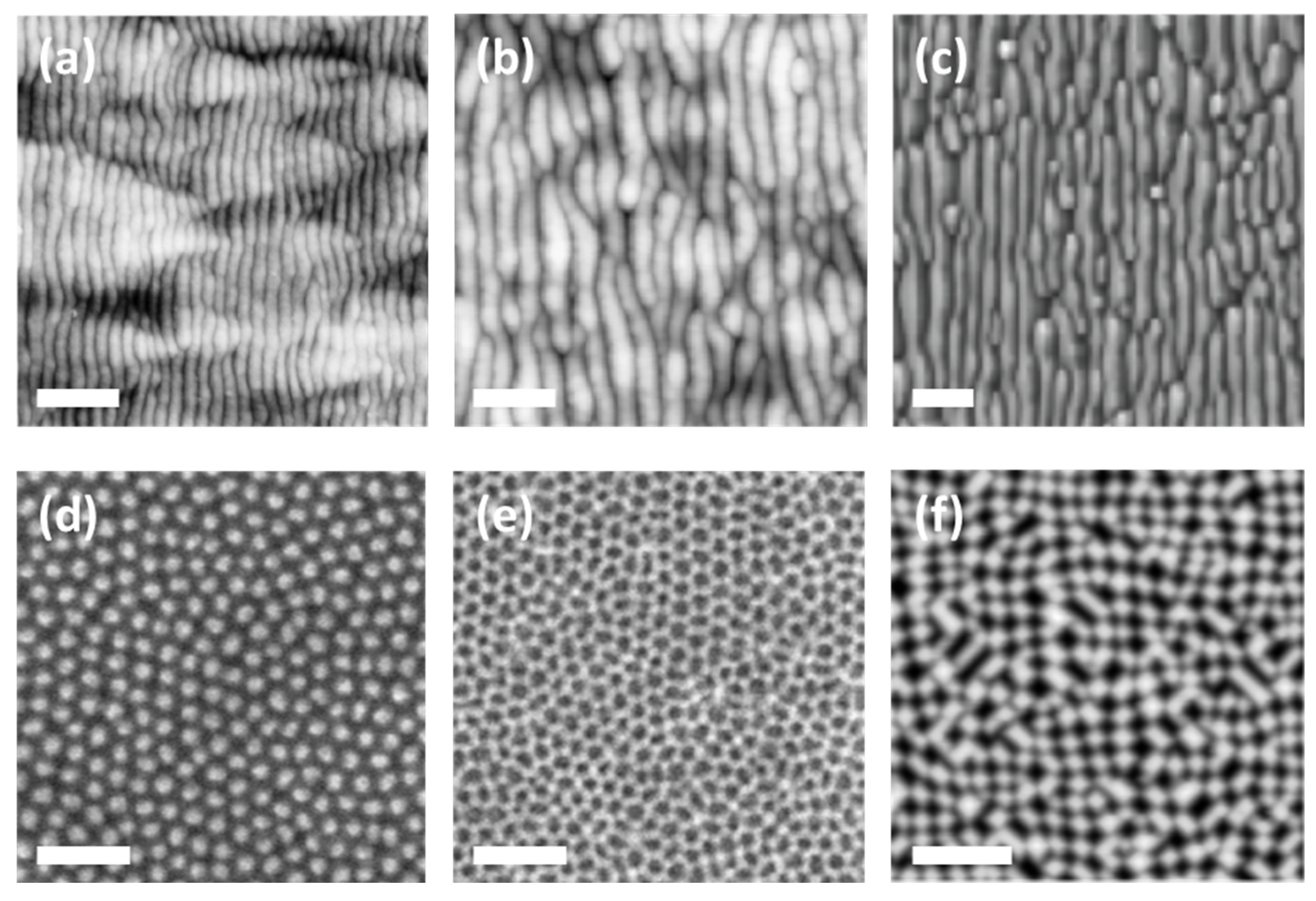
In ion beam sputtering, a solid target surface is irradiated with heavy ions with a kinetic energy ranging from a few tens of eV up to a few hundred keV. This kinetic energy is mostly deposited in the near-surface region of the target material in the form of atomic collisions between the incoming ions and the nuclei of the target atoms. During these initial and subsequent collisions, surface atoms are ejected from the target, resulting in the removal of target material [28,29]. Therefore, ion beam sputtering is routinely employed in the processing of numerous technological surfaces, for instance, in the cleaning, polishing, and etching of semiconductor and optical surfaces [30]. However, as was already observed in the 1960s, ion irradiation of solid surfaces may also lead to the formation of regular nanopatterns. In particular, Cunningham et al. [26] and Navez et al. [25] reported the development of anisotropic surface topographies on metal and glass surfaces, respectively, during keV ion irradiation under an oblique angle of incidence. In particular, the irradiated surfaces were found to exhibit shallow nanoscale ripple patterns whose orientation depended on the incident angle of the ion beam. Since then, similar patterns have been obtained on various amorphous and crystalline materials, including various metals [31,32,33,34,35] and semiconductors [36,37,38,39] (see Figure 1a), but also oxides [40,41,42,43] (see Figure 1b), ionic crystals [44,45,46,47], and even polymers [48,49,50,51] (see Figure 1c). Such ripple patterns typically have a quasi-sinusoidal shape with periodicities ranging from less than 20 nm [52] to almost 1 µm [53], depending on the surface material and the irradiation conditions.
In the last two decades, other pattern types were also found on ion-sputtered surfaces. In 1999, for instance, Facsko et al. reported the formation of isotropic, hexagonally ordered nanodots on GaSb surfaces [54] during normal incidence ion irradiation (see Figure 1d), while the negative of this pattern, i.e., hexagonally ordered nanoholes, was obtained more recently on Ge surfaces (see Figure 1e) [55]. In 2013, checkerboard-like patterns of inverted nanopyramids were also found on crystalline Ge(100) surfaces irradiated at high substrate temperature (see Figure 1f) [56]. Because of this great versatility, both with regard to surface material and pattern type and dimensions, ion beam nanopatterning has become a widely employed technique in the fabrication of functional surfaces for applications in plasmonics [57,58,59,60], (bio)molecular sensing [61,62,63,64,65], photovoltaics [66,67,68], magnetism [69,70,71,72], and nanoelectronics [73,74]. In the remainder of this section, we will briefly summarize the mechanisms of nanoscale pattern formation during ion irradiation with a focus on aspects of high importance in biomaterials applications. For an in-depth discussion of all the processes involved in ion-induced pattern formation and their theoretical description, the reader is referred to a number of reviews that focus specifically on such aspects [75,76,77].
2.1. Roughening vs. Smoothing
It was already shown by Sigmund in 1973 that any rough surface is unstable under ion irradiation [80]. This is because the sputtering yield, i.e., the number of target atoms ejected from the target surface per incident ion, depends on the local surface curvature. This is a direct result of the Gaussian distribution of the deposited energy, which is centered at the mean penetration depth of the ion. In particular, a higher sputtering yield is obtained in depressions than at elevations. This means that depressions are eroded faster than elevations, which is equivalent with an amplification of the initial surface roughness. Since sputtering is an intrinsically stochastic process, this micro-roughening instability will occur also when irradiating atomically flat surfaces, because the first few ion impacts result in the local removal of material and, thus, in the formation of a non-flat surface topography. By itself, however, this mechanism will not lead to the formation of ordered nanopatterns but rather in a self-affine random surface roughness. The former requires the presence of an additional, counteracting smoothing mechanism [81]. In this case, a selection of spatial frequencies will occur and result in one spatial frequency being eroded much slower than all the others are. In a co-moving frame of reference, this will be perceived as an exponential growth of the selected frequency and, thus, the development of an ordered pattern with a fixed periodicity.
In their original model, Bradley and Harper considered thermally activated surface diffusion of the Herring–Mullins type [82,83] as the dominant smoothing mechanism [81]. This immediately suggests that pattern formation kinetics and pattern properties should depend on the target temperature during irradiation. While this was indeed observed in some experiments and especially at elevated temperatures, the observations reported in numerous other studies were incompatible with this interpretation [84]. Under such conditions, alternative, ion-induced smoothing mechanisms are believed to dominate, in particular ion-enhanced viscous flow [85] and ion-induced mass redistribution of the Carter–Vishnyakov type [86].
2.2. Pattern Dimensions
The different nanopatterns fabricated by ion irradiation are typically characterized by two quantities: the lateral periodicity of the pattern λ and the vertical peak-to-peak amplitude Ap2p. When an initial pattern is forming in the beginning of irradiation, i.e., in the so-called linear regime, Ap2p is growing exponentially, while λ remains constant. Only at later stages corresponding to high ion fluences, nonlinear effects become important and result in a saturation of Ap2p [84]. In this regime, the pattern periodicity λ may start to increase with fluence, typically following a power-law dependence, until it saturates as well at very high fluences. This behavior is called interrupted coarsening [84]. The resulting stationary patterns typically have aspect ratios Ap2p/λ between 0.1 and 1.
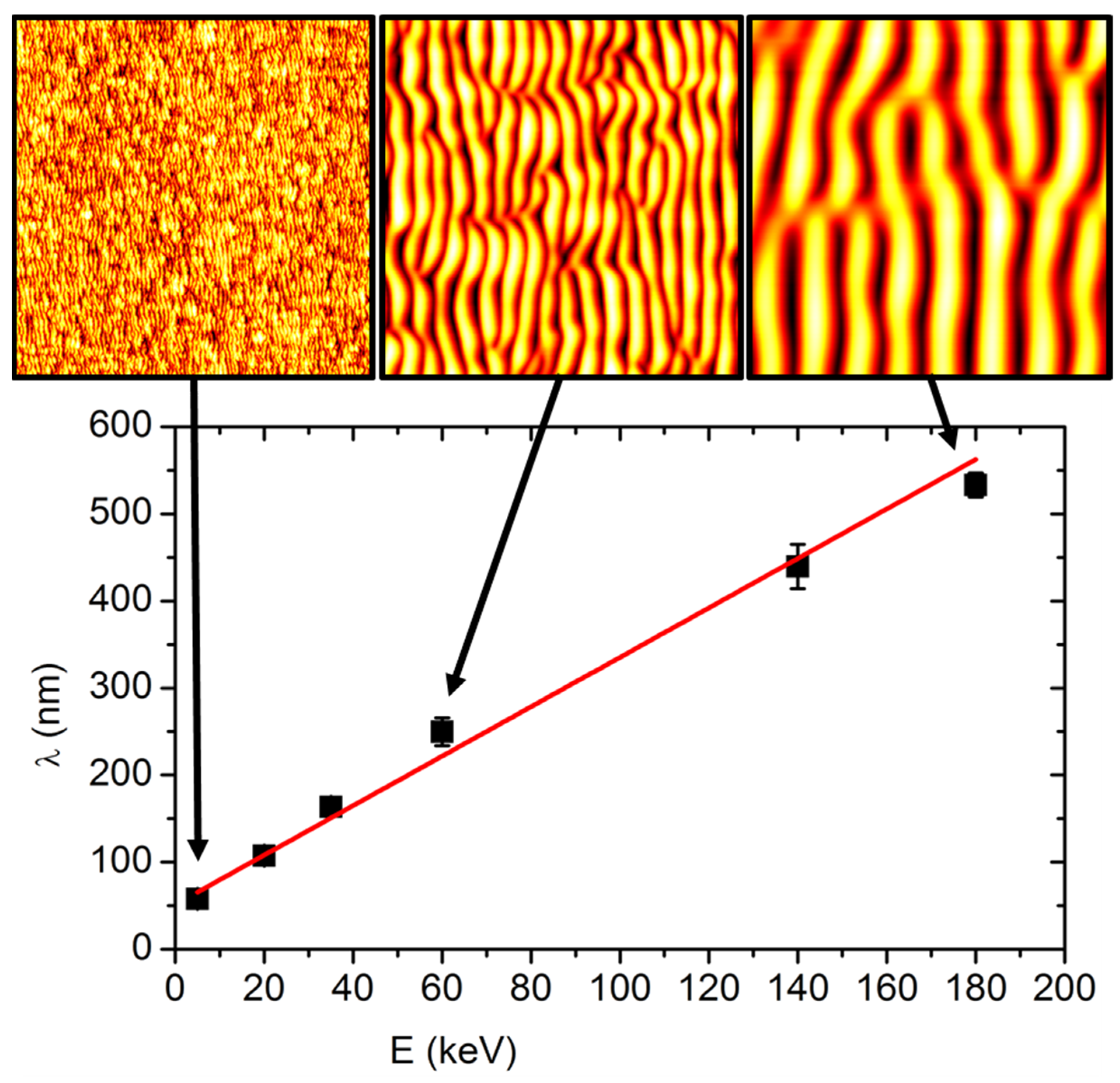
For a given surface, the overall pattern periodicity may depend on a number of experimental parameters, including substrate temperature [87], angle of incidence [88], and most importantly, ion energy. The latter is demonstrated in Figure 2, which displays the dependence of the ripple periodicity λ on the ion energy for the irradiation of Si surfaces with 2 × 1017 cm−2 Xe+ at room temperature and 65° incidence with respect to the surface normal. As can be seen, λ increases linearly with energy from about 60 nm at 5 keV to about 530 nm at 180 keV. This periodicity range covers the dimensions of many cellular and extracellular features such as filopodia tips and collagen fibrils, respectively [89]. It is this possibility of adjusting the dimensions of the generated nanopatterns to match that of certain biological components in such a straightforward manner that makes ion beam nanopatterning very attractive for biomaterials applications.
2.3. Amorphous, Amorphizable, and Crystalline Surfaces
An important factor that has to be considered when nanopatterning biomaterial surfaces by ion beam irradiation is the crystallinity and amorphizability of the target surface. The surfaces of many crystalline materials such as Si or quartz are amorphized within the first few seconds during heavy ion irradiation [28]. This amorphization may result in notable changes in the interaction of the irradiated surfaces with their environment, for instance, due to alterations in surface energy [40,52] or reactivity [90,91]. Metal surfaces, on the other hand, remain crystalline during ion irradiation, which typically results in a richer parameter and pattern space [77]. In particular, the crystallinity of the surface is often associated with Ehrlich–Schwoebel-type barriers to surface diffusion, which, thus, may become anisotropic. In this regime, the symmetry, shape, and orientation of the nanopatterns are no longer governed by the incident ion beam but rather by the crystal structure of the surface, resulting in faceted nanostructures that are oriented along certain crystallographic directions independent of the direction of the ion beam. Furthermore, the orientation and symmetry of these patterns often shows a pronounced dependence on temperature [92]. For polycrystalline surfaces, these effects may result in different orientations of the nanopatterns obtained on different grains [93]. Similar crystallinity-related effects may also be observed for certain amorphizable materials such as Si or Ge at high temperatures, where the ion-induced damage to the crystal lattice is dynamically annealed during sputtering [56]. Finally, it should be mentioned that some oxide surfaces such as MgO(001) [94] and Al2O3(0001) [89] were found to remain crystalline during irradiation even at room temperature, even though the resulting patterns were dictated by the ion beam and not the crystal structure of the surfaces.
2.4. Surface Chemistry
The chemical composition of the irradiated surface is of course an important factor as well, which influences the distribution of the deposited energy, the surface binding energy, and the strength of the different surface smoothing mechanisms. Therefore, it is important to consider the fact that ion irradiation itself may alter the surface chemistry. This is particularly obvious when reactive ions such as O2+ or N2+ are used, which may react with the atoms of the target surface and, thus, form thin oxide and nitride films, respectively. Due to the developing surface topography, these films may display pronounced local variations in thickness and stoichiometry and, thereby, have dramatic effects on the evolution of the nanopatterns, while the fabricated surface may exhibit a highly heterogeneous stoichiometry [95,96].
However, even when inert ions such as noble gas ions are employed, changes in surface chemistry may occur. In polymer materials, for instance, ion impact may lead to both polymer chain scission and crosslinking [51], both of which may affect their mechanical properties. With regard to inorganic surfaces, changes in surface chemistry due to inert ion irradiation occur only in compound materials. Since the sputtering yield depends on the species of the target atoms, different sputtering yields for individual atomic species may be observed in multicomponent materials [84]. In this case, one or more of the atomic species will be sputtered preferentially and, thereby, depleted in the near-surface region. Over time, this depletion will balance the larger (partial) sputtering yield of this species and, finally, result in a stationary state in which the altered surface composition remains constant but is moved into the bulk due to sputter erosion. This preferential depletion/enrichment of atomic species may not only result in an altered chemical composition of the nanopatterned surface but also affect pattern formation itself. For instance, it was shown that the formation of hexagonally ordered nanodots on compound semiconductors (see Figure 1d) critically depends on the preferential enrichment of one atomic species over the other [97].
Finally, the application of broad (defocused) ion beams may result in the deposition of foreign material on the target surface. This may happen in certain irradiation geometries, in which part of the ion beam hits the walls of the vacuum chamber or other equipment in such a way that sputtered material from these surfaces ends up on the target surface. In particular, metallic contaminations of this sort have been found to induce highly complex pattern behaviors and astonishing surface topographies especially on semiconductor surfaces [75]. While the controlled deposition of such contaminants is sometimes considered a promising approach for broadening the range of available patterns, precise control is typically rather difficult to achieve.
From a biomaterials point of view, the different effects discussed in this and the previous subsection stress the importance of a thorough surface-analytical characterization of the nanopatterned substrates prior to contact with biological systems. Small variations in surface energy or stoichiometry may have severe effects on the behavior of adsorbing proteins and the response of adhering cells. This is particularly important because the effects that nanoscale surface topography exerts on biological systems are often rather moderate [89,98] and may easily be masked by such chemical effects.
2.5. Pattern Transfer
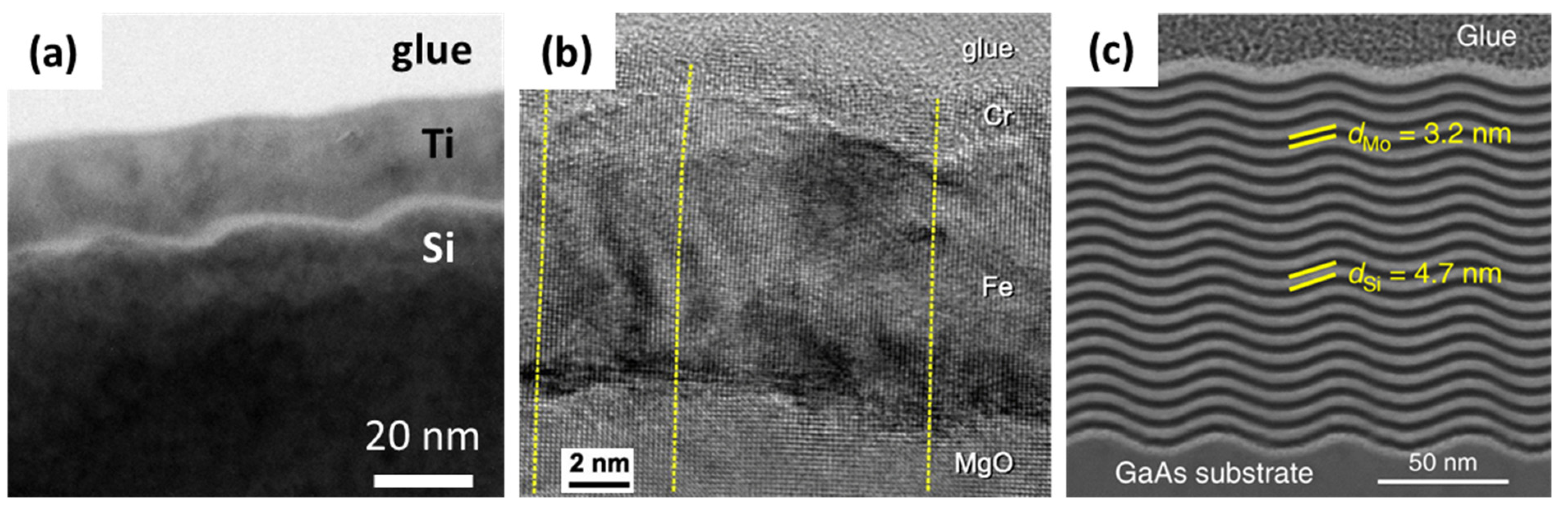
In order to minimize the impact of ion-induced alterations in surface chemistry and crystallinity or to adjust surface chemistry and surface topography independently, the fabricated nanopatterns can also be transferred into other materials with only minor variations in their surface topography. The most straightforward way to achieve this is the coating of the nanopatterned substrates with continuous thin films. In the literature, this approach has mostly been applied to thin metal films but can also be extended to non-metallic films [27]. In order to achieve high conformity between the substrate and the film surface, the film deposition parameters have to be carefully selected. In general, normal-incidence deposition is preferred, as deposition under an oblique angle of incidence may result in material accumulation on the pattern crests, leading to non-conformal columnar growth [99]. If the material to be deposited does not wet the substrate surface, application of an intermediate buffer layer may be necessary to ensure perfect replication of the substrate pattern [100,101]. Furthermore, in the case of polycrystalline films, the disorder between the different grains in the film may result in a loss of conformity already at low film thicknesses. In such a case, magnetron sputter deposition with an applied negative bias may be used to achieve dense and highly conformal films with no apparent surface texture other than the replicated nanopattern (see Figure 3a) [98,102]. If the nanopatterned substrate surface is crystalline, highly conformal films can also be grown epitaxially, if the lattice constants between film and substrate material are a match (see Figure 3b) [94]. Finally, various layer stacks [69,101,103] and multilayers [27,104] have also been grown on nanopatterned substrate that replicated the substrate topography very well (see Figure 3c).
Pattern transfer into polymeric materials is more complex. Two strategies have been reported so far. Dell’Anna et al. employed thermal nanoimprinting lithography via an intermediate mold [105]. This intermediate mold was fabricated by UV crosslinking of a perfluoropolyether (PFPE) resin on a nanorippled Ge surface with about 300 nm periodicity. After stripping the intermediate PFPE mold from the Ge template, it was imprinted at elevated temperature into a cyclic olefin copolymer (COC) foil. After cooling down and removal of the PFPE mold, the COC foil surface exhibited a high-quality replica of the Ge nanopattern. Repetto et al. used a nanorippled glass substrate with about 200 nm periodicity as the template [64]. Polydimethylsiloxane (PDMS) solution was deposited on the template surface and left to solidify at room temperature. After a final annealing step, the PDMS replica was removed from the template, exhibiting the negative of the original template pattern on its surface. These transfer approaches are particularly interesting for biomaterials applications because they enable the transfer of a given nanopattern from a potentially toxic material such as GaAs to an established biocompatible polymer material. Furthermore, a large number of identical samples can be produced in this way using only a single nanopatterned substrate as the template. This is particularly advantageous for cell culture studies, which typically require very large numbers of identical substrates. However, it is not clear so far whether such imprinting approaches also allow for the transfer of smaller patterns with periodicities below 100 nm.
3. Ion Beam-Nanopatterned Surfaces in Contact with Biomolecules and Cells
3.1. Biomolecular Adsorption
3.1.1. Proteins and Peptides
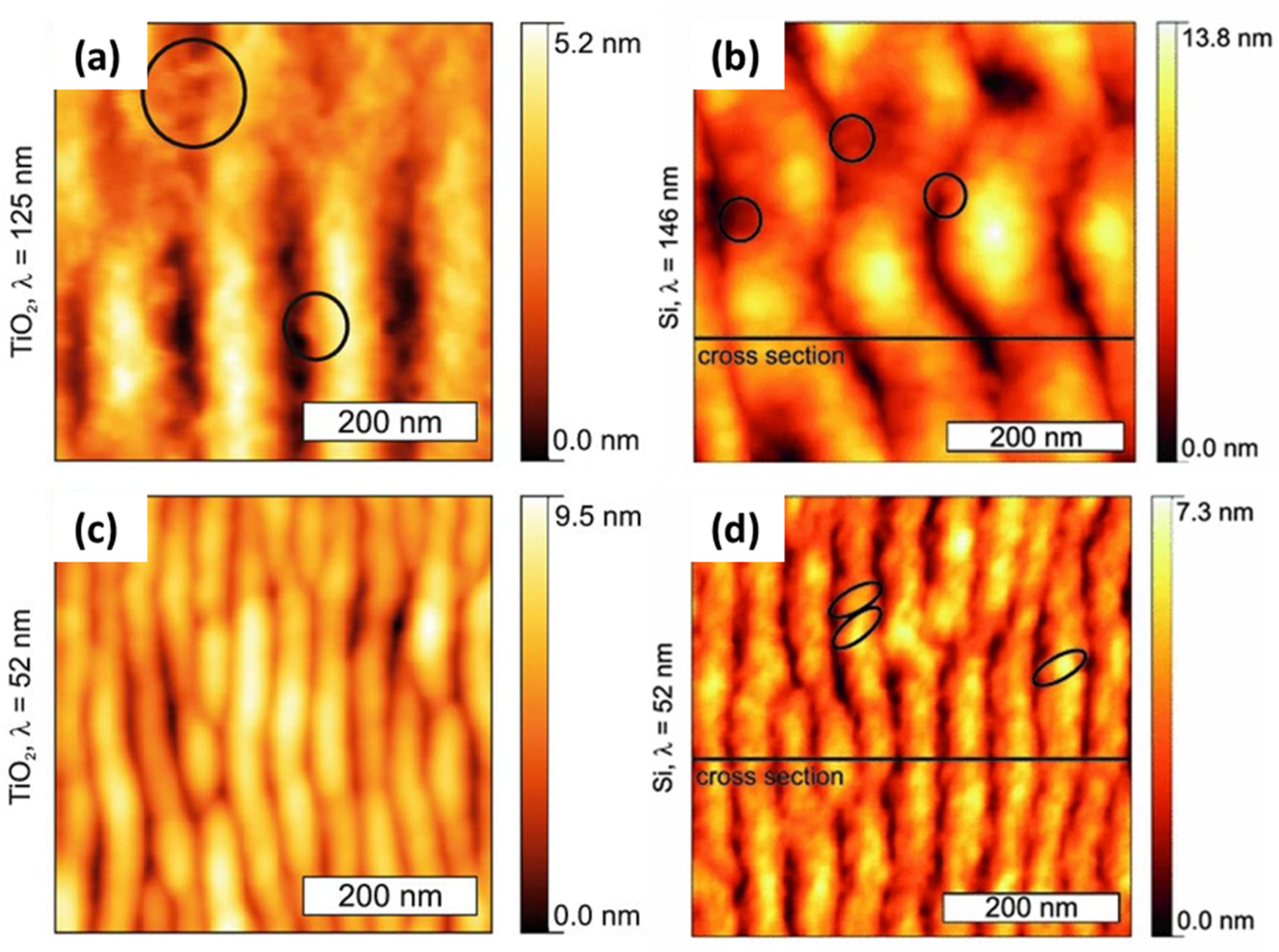
In a pioneering study, Sommerfeld et al. for the first time investigated protein adsorption at nanorippled surfaces fabricated by ion beam irradiation [106]. Nanoscale ripple patterns having different periodicities ranging from about 50 to about 150 nm were obtained on Si and TiO2 surfaces after oblique Xe+ irradiation at ion energies between 5 and 20 keV. Adsorption of human plasma fibrinogen (HPF), which is involved in blood clotting [107], at these surfaces was then studied by AFM (see Figure 4). The adsorbed HPF was found to adopt a globular conformation on nanorippled TiO2 and oxidized Si (SiOx/Si) surfaces with large periodicities > 100 nm. At small periodicities, however, the two surface materials displayed astonishing differences. HPF was found to adsorb in a stretched conformation on nanorippled SiOx/Si surfaces with periodicities ≤ 68 nm, with some indications for preferential alignment either parallel (68 nm periodicity) or perpendicular (52 nm periodicity) to the ripples. In contrast, HPF adsorption was effectively suppressed on the nanorippled TiO2 surface with a periodicity of 52 nm (see Figure 4c). Therefore, this was the first indication that such shallow nanopatterns with aspect ratios ≤ 0.1 can efficiently alter the behavior of adsorbing proteins.
More recently, our lab has evaluated the effect of nanoscale ripple patterns on SiOx/Si and TiOx/Ti surfaces on three different globular proteins with widely differing molecular weights, sizes, and net charges [98]. To ensure comparability of the generated patterns on these two surfaces, Si wafers were irradiated with 500 eV Ar+ at 67° incidence with respect to the surface normal, resulting in a pattern with about 30 nm periodicity and about 1.5 nm peak-to-peak amplitude. At these surfaces, a highly conformal 15–20 nm thick Ti film was grown using magnetron sputter deposition (see Figure 3a). The nanopatterned SiOx/Si and TiOx/Ti surface, thus, had very similar surface morphologies. Adsorption of the three globular proteins myoglobin (MGB), bovine serum albumin (BSA), and thyroglobulin (TGL) at these nanopatterned and corresponding flat surfaces was investigated in situ and ex situ using ellipsometry and AFM, respectively. Depending on the particular protein and material combination, the nanoripples were found to affect protein adsorption in several ways. For instance, preferential alignment along the ripples on both oxide surfaces was observed for the small, positively charged protein MGB, whereas no effect of the ripple pattern on the SiOx/Si surface was observed for the larger and strongly negatively charged protein TGL. On the TiOx/Ti surfaces, however, the presence of the ripple pattern resulted in a reduced thickness of the adsorbed TGL film, indicating different denaturation states of the adsorbed proteins. Similar observations were made also for the smaller and less negatively charged protein BSA, where different degrees of denaturation could be verified on the flat and rippled SiOx/Si surfaces. In a follow-up study that employed TiOx/Ti films with different surface morphologies including those on nanorippled Si substrates, we could further show that the adsorption of these three proteins is governed by different surface statistical parameters [102]. In particular, we found that BSA adsorption is governed mostly by root-mean-square (RMS) surface roughness, while TGL adsorption is more sensitive toward surface skewness and kurtosis. This demonstrates the importance of a precise tailoring of surface morphology at the nanometer level to enable the rational control of biological response to biomaterial surfaces. Ion beam nanopatterning appears to be a viable and versatile tool in this regard.
Finally, in a recent work from our lab, the effect of such 30 nm ripple patterns on SiOx/Si surfaces on the surface-assisted aggregation of a small peptide hormone called human islet amyloid polypeptide (hIAPP) was investigated [108]. The aggregation of hIAPP into cytotoxic amyloid fibrils is a key intermediate step in the development of type 2 diabetes mellitus [109]. Quantitative characterization of the aggregate morphologies at the flat and nanorippled surfaces by time-lapse AFM revealed that the presence of the nanopattern affected the pathway of hIAPP aggregation. In particular, hIAPP fibrillization at the nanopatterned surface was retarded compared to the flat surface. Instead, peptide aggregation was dominated by the formation of large amorphous aggregates. This demonstrates that surface nanopatterning not only affects protein adsorption and denaturation but may also influence protein–protein interactions.
3.1.2. DNA
While less relevant in the context of medical implants, DNA adsorption at various technologically relevant surfaces is an important issue in bioanalysis and biosensing [110,111,112]. The adsorption of plasmid DNA at ion beam-nanopatterned TiO2 surfaces was investigated by Majumder et al. [113]. The authors irradiated TiO2 single crystal surfaces with 3 keV Ar+ ions at slightly off-normal incidence, which resulted in the formation of randomly distributed nanodots, the size of which increased with ion fluence. At the irradiated surfaces, adsorbed plasmid DNA films displayed some morphological differences, which were attributed, however, not primarily to the nanoscale surface topography but to an increased hydrophilicity due to ion bombardment.
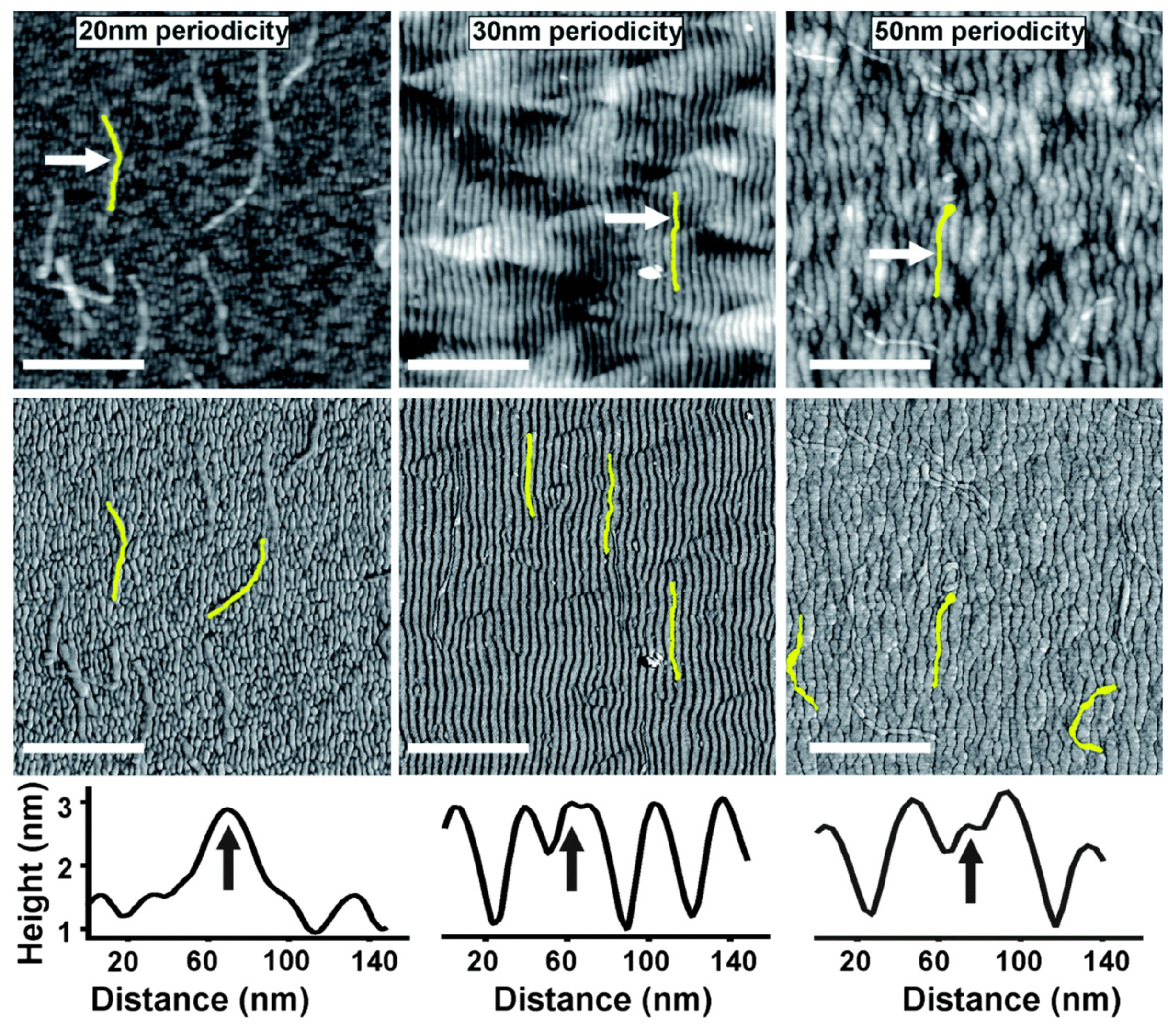
In a more detailed study by Teshome et al., the adsorption of DNA origami nanotubes at nanorippled SiOx/Si surfaces with varying periodicities was investigated [114]. Ordered nanoscale ripple patterns with periodicities of about 20 and 30 nm were fabricated by oblique Ar+ irradiation of Si wafers at ion energies of 300 and 500 eV, respectively, whereas larger ripple patterns with about 50 nm periodicity were obtained by 5 keV Xe+ irradiation. Adsorption of negatively charged DNA origami nanotubes with a diameter and length of 6 and 412 nm, respectively, at the like-charged SiOx/Si surfaces was facilitated by Mg2+ ions in the buffer solution. For all three nanopatterned SiOx/Si surfaces, the nanotubes were showing preferential alignment along the ripple patterns (see Figure 5). However, the pattern with 30 nm periodicity displayed by far the largest alignment yield with more than 70% of the DNA origami nanotubes adsorbed in the ripple valleys, where they perfectly followed the pattern. Based on finite element simulations and further experiments with different Mg2+ concentrations, it was concluded that nanotube alignment results from an inhomogeneous electrostatic field distribution along the nanorippled SiOx/Si surface with the obtained degree of alignment depending on the dimensions of the nanopatterns, the dimensions of the nanotubes, and the Debye length of the adsorption buffer. This interpretation was further supported by a follow-up study, which attempted to decorate the pre-aligned DNA origami nanotubes with gold nanoparticles at a lower Mg2+ concentration [115]. Under such conditions, the DNA origami nanotubes were displaced from the ripple valleys, resulting in reduced alignment. This is in agreement with Mg2+ ions being released from the DNA–SiOx interface, which leads to weaker binding of the DNA origami nanotubes and, therefore, a stronger propensity for them to move along the surface, in particularly during washing of the sample surface.
Even though only a handful of studies so far have examined biomolecular adsorption at nanopatterned surfaces fabricated by ion beam irradiation, the examples discussed in this section clearly demonstrate that ion beam nanopatterning may be used to control the behavior of adsorbing biomolecules on several levels. In particular, the preferential alignment of different proteins as well as DNA nanotubes on nanoscale ripple patterns was observed [98,106,114]. This, however, is not too surprising, since such surfaces are frequently used as templates for the alignment of various nanostructures [57,58,59,61,116,117,118,119,120,121]. More intriguingly, it was also shown that the presence of such nanopatterns sometimes hinders or even completely suppresses protein adsorption [98,106]. Ion beam nanopatterning may, therefore, turn into a valuable tool in the fabrication of antifouling surfaces [122]. Furthermore, nanorippled surfaces were also found to affect the conformation of adsorbed proteins [98,106], which may be a beneficial feature in applications that require controlled protein unfolding, for instance, to expose cell-binding RGD domains [123]. Unfortunately, all these effects appear to depend strongly on the physicochemical properties of the biomolecules and the surface material, as well as on the dimensions of the nanopatterns, which makes them hard to understand and even harder to control. More detailed studies that systematically investigate the interaction of different proteins with different nanopatterned surfaces by a number of complementary surface analytical techniques will be required to shed further light on these issues.
3.2. Cell Response
3.2.1. Mammalian Tissue Cells
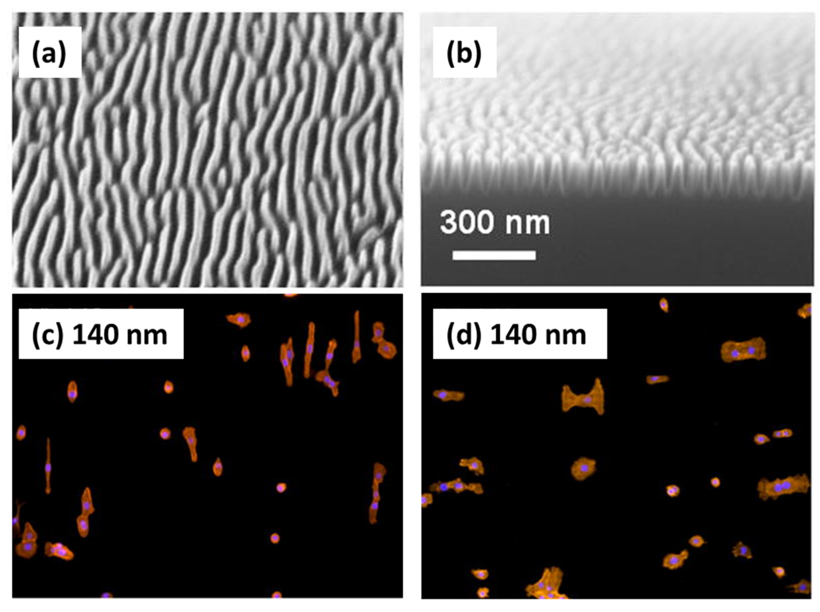
The first study to investigate cellular response to ion beam-nanopatterned surfaces employed high-aspect-ratio ripple patterns fabricated in a two-step process [124]. Here, periodic ripple patterns with periodicities between 60 and 140 nm were produced on Si surfaces by 1–8 keV nitrogen ion irradiation. This, however, resulted also in the formation of a thickness-modulated SixNy top layer [74]. The thickness of this top layer was largest at the ripple slope facing the ion beam. Therefore, it could be used as a hard etch mask in a subsequent reactive ion etching (RIE) step to increase the depth of the ripple valleys to about 200 nm (see Figure 6a,b). Cellular response to the so-fabricated high-aspect-ratio nanopatterns was investigated using human corneal epithelial cells (HCEC). In standard epithelial growth medium, the authors observed HCEC contact guidance parallel to the ripples for periodicities of 80 and 140 nm but not for 60 nm. In serum-free EpiLife® medium, however, significant contact guidance occurred also at 60 nm periodicity. In addition, further analysis also revealed a stronger degree of HCEC alignment at the larger periodicities. It should also be noted that in this particular medium, the cells were aligned perpendicular to the ripples, which underscores the importance of soluble factors (see Figure 6c,d). Finally, it was demonstrated that HCEC contact guidance by lithographically produced micropatterns with 4 µm pitch can be strongly enhanced by overlay with a 70 nm ripple pattern [124].
A subsequent set of studies by Riedel et al. investigated the potential of ion beam nanopatterning for controlling cellular response toward biomedical Ti6Al4V ELI, one of the most widely employed orthopedic implant materials [125]. For this alloy, a hierarchical surface topography was obtained after normal incidence irradiation with 700 and 1100 eV Ar+ [126], which can be attributed to its polycrystalline microstructure and comparably large surface roughness [127]. In particular, randomly distributed plateaus and valleys were observed on a micrometer scale, while some of the grains additionally displayed ripple patterns with about 20 nm periodicity. Using rat mesenchymal stem cells (MSC), the authors observed an increase in early cell spreading and mobility in the first seven days of culture on the ion-irradiated surfaces. Effects on long-term cellular response, however, were less conclusive [126].
To obtain more regular topographic features on Ti6Al4V surfaces, Riedel et al. also employed oblique ion beam irradiation, which resulted in the formation of tilted, needle-like structures with tips about 200 nm in size [128]. Depending on the incident angle, two different surface morphologies were obtained after 1.2 keV Ar+ irradiation. At an incident angle of 30° with respect to surface normal, the needles were around 4 µm in height. At 75° incidence, however, their height was reduced to less than 2 µm. Cellular response to these surfaces was investigated using human fetal osteoblasts. Within the first seven days of culture, pronounced differences in cell morphology were observed for the two irradiated surfaces and an untreated control. Compared to the flat control, the cells on the surface irradiated at 30° incidence showed rounded morphologies and reduced spreading. For 75° irradiation, however, preferential cell elongation and alignment along the needles was observed. The differences in surface topography also influenced cell density. Whereas the cell densities on untreated and 75°-irradiated surfaces were comparable, cell density on the 30°-irradiated surface was reduced by about 40%.
Finally, Riedel et al. irradiated Ti6Al4V surfaces with 300 eV He+ ions under normal incidence by direct extraction from a plasma [129]. This resulted in surface morphologies composed of networks of pores uniformly distributed over the complete sample surfaces. Pore formation was attributed not to material removal by sputtering but rather to the formation of embedded He bubbles. By varying the applied ion current, the pore diameter could be adjusted in the range from a few hundred nanometers to several microns in diameter, with the smaller pores occurring in higher density than the larger ones. The influence of these porous surfaces on cellular response was again studied using human fetal osteoblasts. No remarkable differences in cell proliferation, cell density, and cell spacing were observed for irradiated and non-irradiated substrates. Cell viability assays, on the other hand, indicated that the irradiated surfaces displayed decreased initial cell adhesion. Once cells were established on the irradiated surfaces, however, cellular activity was increased again.
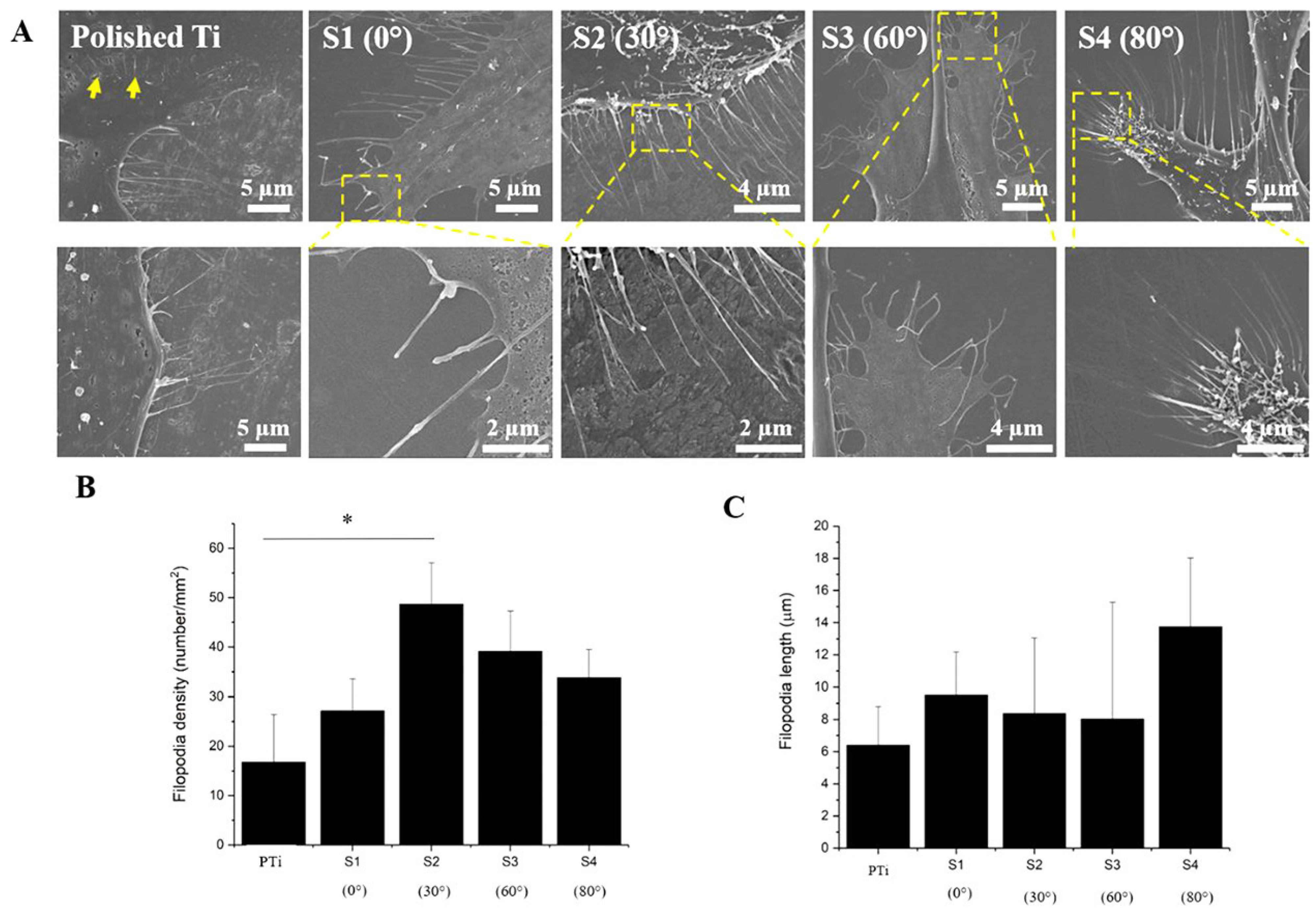
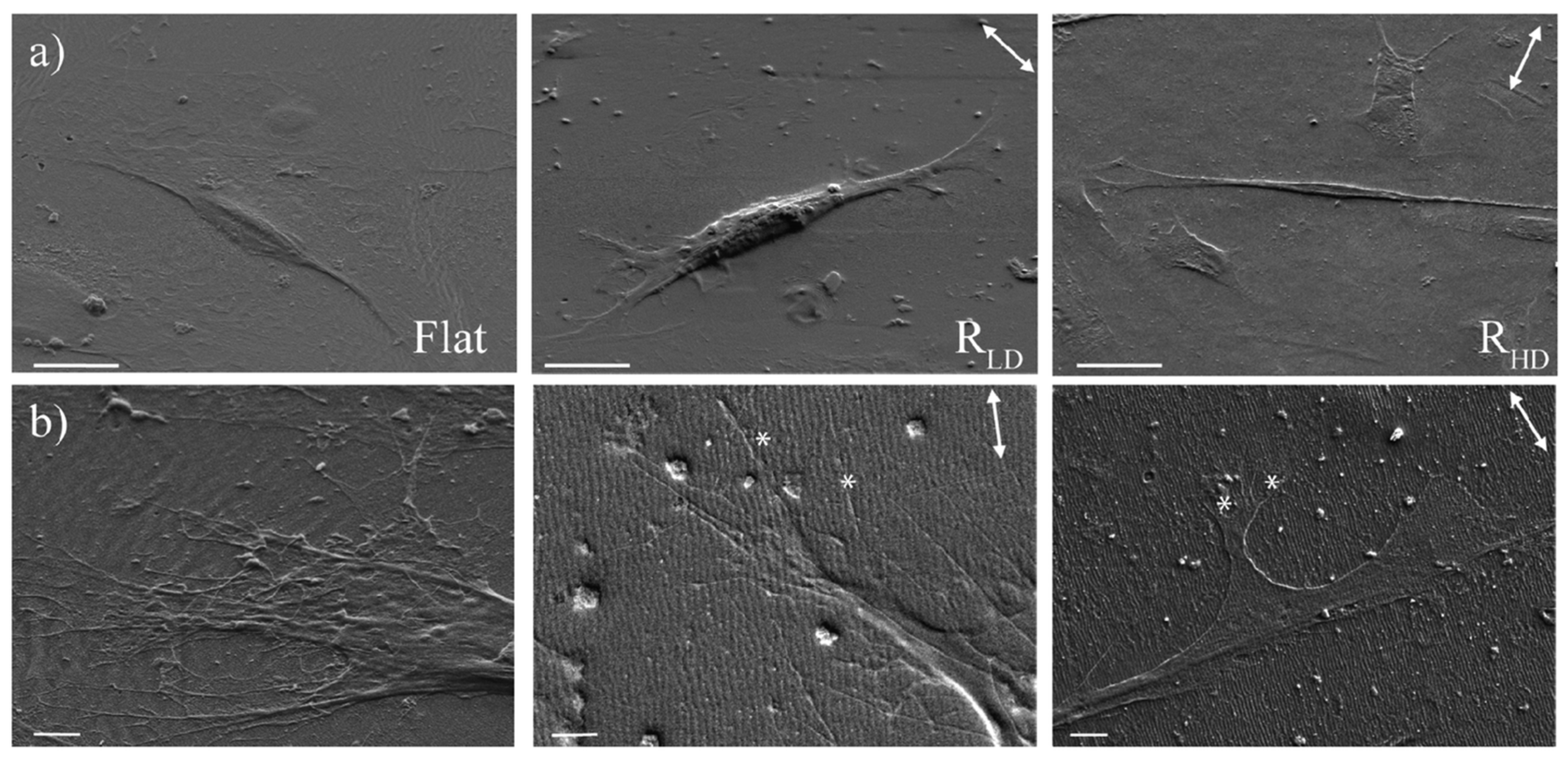
Nanopatterned Ti6Al4V surfaces were also produced by Civantos et al. using 1 keV Ar+ irradiation at various incident angles [93]. At normal and oblique, non-grazing incidence, surface topographies similar to those described by Riedel et al. [126] were obtained, i.e., sub-100 nm ripple patterns with different orientations on different grains. At grazing incidence (80° with respect to the surface normal), however, the surface displayed a homogeneous pattern of ripples with about 50 nm periodicity oriented parallel to the ion beam direction that crossed different grains without a change in direction. Such patterns are frequently observed for grazing incidence irradiation of polycrystalline metal surfaces [127]. Human aortic smooth muscle cells (HASMCs) were cultured on these surfaces to evaluate the effect of the different surface topographies on cell viability, adhesion, and morphology. While no differences between the ion beam-irradiated and the untreated control surfaces with regard to cell viability could be established, larger cell spreading was observed for the nanopatterned surfaces. Most intriguingly, the authors found an increased filopodia density for HASMCs cultured on the surface irradiated under 30° incidence with respect to the surface normal (see Figure 7). All these findings indicate that the nanoscale surface topographic features promote HASMC–surface interactions with cell filopodia preferentially attaching to nanorippled grains.
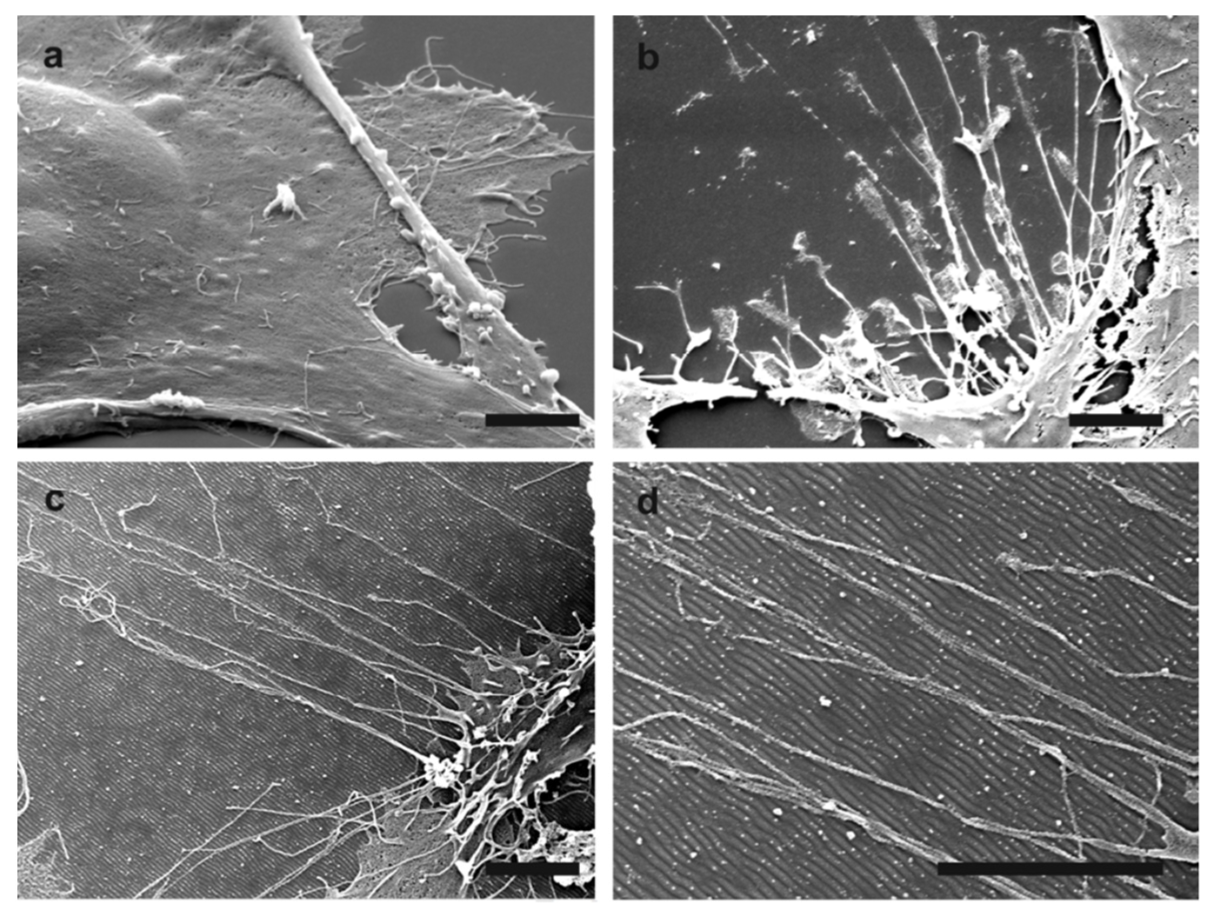
Apart from titanium-based alloys, other materials have been nanopatterned as well to evaluate the effects on cell response. Alumina, for instance, is another material frequently used in orthopedic and dental implants [130]. To evaluate the effect of nanoscale surface topography on cellular response to alumina surfaces, Wittenbrink et al. patterned the surfaces of Al2O3(0001) single crystals using 500 eV Ar+ and 35 keV Xe+ irradiation at 50° incidence with respect to the surface normal [89]. This resulted in ripple patterns with periodicities of 24 and 179 nm, respectively. Furthermore, these patterns had a very low aspect ratio with corresponding peak-to-peak amplitudes of only 0.7 and 11.5 nm, respectively. Cell viability and morphology in response to these nanopatterns as well as flat control substrates were evaluated using the human osteosarcoma cell line MG-63. For the larger ripple pattern with 179 nm periodicity, significantly enhanced proliferation of the MG-63 cells was observed. While this pattern did not induce any cell alignment, the SEM images shown in Figure 8 revealed preferential alignment of pseudopodia along the ripples. For the smaller ripple pattern with 24 nm periodicity, no significant effects on cell proliferation or pseudopodia orientation were observed. However, MG-63 cells cultured on those smaller patterns were found to exhibit longer extensions, which demonstrates that these cells are in general able to recognize and react to topographic surface features with heights even below 1 nm.
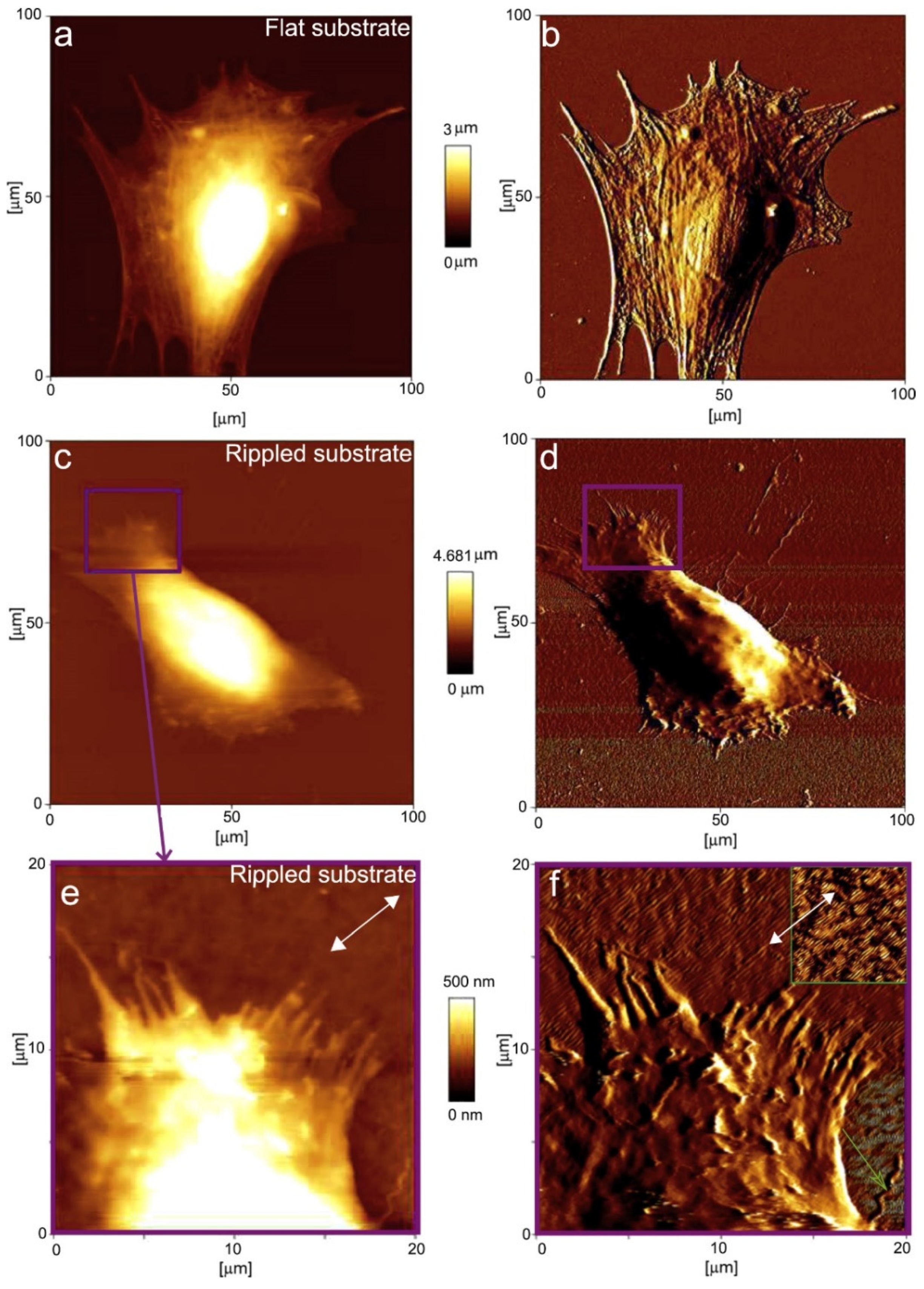
In addition to such implant-related investigations, a few studies also focused on cells of the nervous system. Pedraz et al., for instance, investigated the response of mouse neural stem cells (NSCs) to nanorippled glass surfaces produced by oblique Ar+ irradiation at 800 eV [131]. The resulting ripple pattern had a periodicity and peak-to-peak amplitude of 200 nm and about 40 nm, respectively. It was found that NSC adhesion at the nanopatterned surfaces was strongly reduced compared to flat glass. This was attributed to a pinning of NSC filopodia by the ripple patterns, which prevented the cells from spreading at the surfaces. This pinning was a result of matching dimensions of the filopodia (60–200 nm in thickness [132]) and the ripple pattern (200 nm periodicity, 40 nm peak-to-peak amplitude). Indeed, AFM images revealed a preferential alignment of the NSC filopodia parallel and perpendicular to the ripples (see Figure 9), similar to that observed for MG-63 cells at the rippled Al2O3(0001) surfaces with similar periodicity (Figure 8c,d) [89]. As the authors discussed, these two filopodia configurations result in the strongest filopodia adherence to those surfaces, which may, for instance, lead to a zigzag conformation of adhering filopodia, as highlighted in Figure 9f (green arrow).
Masciullo et al. investigated the response of Schwann cells (SCs) to nanoscale ripple patterns on polyethylene terephthalate (PET) [133]. These nanopatterns were first produced on germanium surfaces by 26 keV Au+ irradiation under off-normal incidence and then transferred into PET using thermal nanoimprinting lithography (see Section 2.5 for details). This was achieved for two different patterns having periodicities of about 270 nm and 290 nm, respectively. SCs cultured on the nanorippled surfaces showed enhanced viability and spreading within the first 48 h compared to flat control surfaces, in particular for the larger ripple pattern. For longer culture times, SC proliferation rate and viability were comparable to those of the controls. Furthermore, SCs cultured on the nanorippled surfaces were elongated and aligned perpendicular to the direction of the ripples. Again, these morphological variations were most pronounced for the larger ripple periodicity. SEM images further revealed that despite the cells being aligned perpendicular to the ripple pattern, their filopodia were aligned along the ripples (see Figure 10). Finally, the presence of the nanopatterns also resulted in actin enrichment and polarization in the SCs.
The bulk of the work discussed in this section suggests that ion beam nanopatterning can be a valuable tool for controlling cellular response to abiotic surfaces. Larger patterns with periodicities of about 200 nm and above appear to have stronger effects on cell proliferation, viability, and contact guidance than smaller ones. Nevertheless, small patterns with periodicities below 100 nm and peak-to-peak amplitudes down to the sub-nanometer level have also been shown to induce significant changes in cell morphology. This in particular concerns the density, length, and alignment of cell extensions such as filopodia [89,93]. This in combination with the fact that ion beam surface modification is a well-established and scalable technology suitable for the processing of large surface areas makes ion beam nanopatterning a promising method for tissue engineering applications.
3.2.2. Bacteria
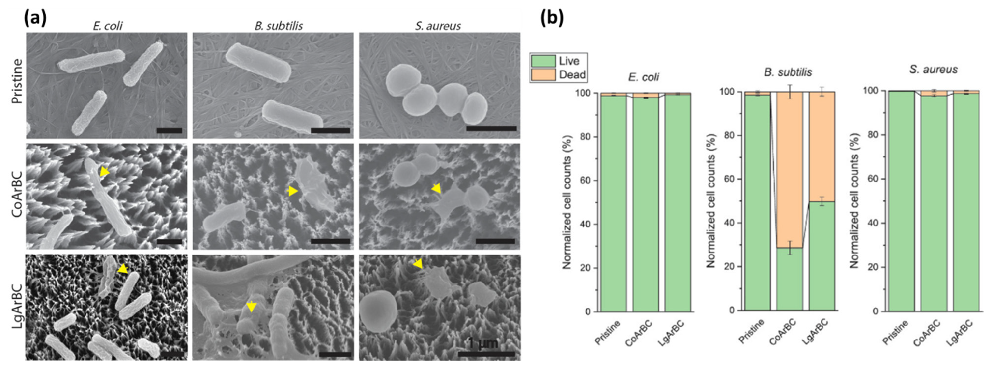
All the studies discussed above investigated ion beam-nanopatterned surfaces in contact with mammalian tissue cells, aiming at applications in reconstructive medicine and tissue engineering. Recently, however, the potential of ion beam nanopatterning in the fabrication of antimicrobial surfaces was explored as well. While it is well established that topographically nanopatterned surfaces can exhibit contact-killing properties by inducing the rupture of the bacterial plasma membrane, such patterns typically require comparatively high aspect ratios [134,135]. To achieve such high aspect ratios, Arias et al. irradiated dried bacterial cellulose (BC) hydrogels with 1 keV Ar+ ions at normal incidence [136]. With increasing ion fluence, this resulted in a transition of the original BC morphology that is composed of interlaced ribbons to self-standing spike-like nanostructures 50–70 nm in width and about 400 nm in height. This was also accompanied by an increase in the effective Young’s modulus. Nanostructure formation was attributed to a transition from chemical sputtering at low fluences to physical sputtering at high fluences. Most remarkably, these high-aspect-ratio nanostructures did not collapse or change their shape upon heat sterilization and immersion in aqueous environments, rendering them suitable for a wide range of in vitro and possibly in vivo applications. In a follow-up study from the same lab, different BC types were compared, namely commercial BC (CoBC) and lab-grown BC (LgBC), which had different ribbon widths [137]. These differences resulted in smaller nanostructure dimensions for LgBC, despite maintaining a constant aspect ratio of about 5. The interaction of these nanostructured as well as untreated BC hydrogels with Gram-positive and Gram-negative bacteria was then investigated. In general, nanopatterned CoBC showed a stronger bactericidal activity than irradiated LgBC (Figure 11). Furthermore, it was found that both nanostructured BCs had a stronger bactericidal effect on the Gram-positive bacterium Bacillus subtilis than Gram-negative Escherichia coli (see Figure 11), despite B. subtilis having a stiffer cell envelope. It was further observed that the geometry of the Gram-positive bacteria played an important role as well. In particular, rod-shaped B. subtilis was more susceptible to the contact-killing nanopatterned BC hydrogels than spherical Staphyloccus aureus (see Figure 11). Most importantly, however, the authors could demonstrate that these nanopatterned BC hydrogels have no effect on the viability of murine preosteoblasts, which is an important prerequisite for applications of antimicrobial coatings on medical implants.
This work demonstrates the great potential of ion beam nanopatterning to serve not only as a tool for enhancing biocompatibility of implant surfaces but also to minimize their microbial colonization. Furthermore, it serves as an excellent example that the application of this well-established technique to novel and in particular organic materials systems may result in new nanopatterned surface morphologies with unexpected biofunctional properties.
4. Conclusions
As we have seen in this review, ion beam nanopatterning is an attractive technique for the fabrication of well-defined model surfaces for the investigation of the numerous effects that nanoscale topographic surface features may exert on interacting biomolecules and cells. In this regard, the possibility to precisely tune the pattern dimension from about 10 to about 1000 nm is particularly interesting for biomaterials applications. While larger nanopatterns with periodicities of a few hundred nanometers have been found to have stronger effects on adhering cells than equivalent ones with periodicities below 100 nm, the latter may, nevertheless, affect the adsorption of various biomolecules at several levels. Furthermore, the fact that broad ion beam irradiation enables the homogeneous and parallel patterning of large surface areas with well-defined nanopatterns represents a significant advantage over several other and in particular serial techniques. However, since ion-induced pattern formation is a self-organized process, the generated patterns will always exhibit defects. While the density of pattern defects and pattern regularity in general can be adjusted within certain limits, for instance, by tuning the irradiation conditions [78] or applying sequential irradiation steps [138], some degree of disorder will remain. While this is certainly a disadvantage compared to lithographic techniques that enable the fabrication of arbitrary patterns with precisely adjusted regularity or disorder [12], similar limitations are faced also by other methods based on self-organization or self-assembly such as colloidal lithography [23] or anodic oxidation [16].
With few exceptions [128,129,137], the studies discussed in this review utilized ion-induced ripple patterns, presumably because ripple patterns are the most universal and can be generated on almost any surface. However, from a fundamental point of view, comparing the effects of different pattern types may be a rather interesting future endeavor. For instance, the importance of anisotropy could be assessed by comparing ripple and dot patterns of comparable amplitudes and periodicities after transfer into a common, biocompatible material. The role of the particular shape of the employed patterns could also be investigated in detail, for example, by comparing quasi-sinusoidal and faceted ripple patterns generated on amorphous and crystalline surfaces, respectively. Similarly, positive and negative replicas of a given pattern may be produced using nanoimprinting lithography. Such experiments may provide viable insights into the mechanisms of topography sensing by cells.
From a more applied point of view, the translation of ion beam nanopatterning from model surfaces to real-world medical implant surfaces faces two challenges. First, in order to generate well-defined nanopatterns, comparatively smooth substrate surfaces are required. For polycrystalline metal surfaces such as Ti6Al4V, each grain presents atomically flat crystal facets that can be patterned individually with ripple patterns aligned along their dominant crystallographic directions by normal or near-normal incidence irradiation [93,126]. This, however, will not result in a homogeneous surface pattern. For this, oblique incidence irradiation of highly polished surfaces is required to minimize the effects of geometric shadowing [93]. For ceramic materials such as alumina or bioglass, the situation is even more difficult. These materials are typically produced by particle sintering and, thus, have very rough and porous surfaces [139]. So far, it appears dubious whether such surfaces can be nanopatterned by ion beam irradiation.
The second challenge concerns the shape of medical implants. While all the studies discussed in this review have dealt with flat, two-dimensional substrate surfaces, real-world implants have complex, three-dimensional shapes with sometimes very pronounced curvatures. Patterning such curved surfaces will require the application of an ion beam with a small (possibly sub-millimeter) diameter and high flux density that is scanned in three dimensions over the implant surface using a multi-axes stage. Fortunately, such setups already exist [140,141,142] and could be adapted for the (selective) patterning of the complex surfaces of implants. Therefore, ion beam nanopatterning of biomaterial surfaces appears to be a promising tool not just for the fabrication of model surfaces for basic research but potentially also for the engineering of metallic implant surfaces for clinical applications.
Author Contributions
Writing—original draft preparation, Y.Y.; writing—review and editing, Y.Y. and A.K.; supervision, A.K.; project administration, A.K.; funding acquisition, A.K. All authors have read and agreed to the published version of the manuscript.
Funding
This research was funded by Deutsche Forschungsgemeinschaft DFG, grant number KE 1944/4-1.
Acknowledgments
We thank I. Winkler, F. Nierobisch, and F. Ludewig, Helmholtz-Zentrum Dresden-Rossendorf, for performing the ion irradiations of the samples shown in Figure 2.
Conflicts of Interest
The authors declare no conflict of interest.
References
- Ratner, B.D.; Hoffman, A.S.; Schoen, F.J.; Lemons, J.E. (Eds.) Biomaterials Science; Elsevier: Amsterdam, The Netherlands, 2013; ISBN 9780123746269. [Google Scholar]
- Dee, K.C.; Puleo, D.A.; Bizios, R. An Introduction to Tissue-Biomaterial Interactions; John Wiley & Sons, Inc.: New York, NY, USA, 2002; ISBN 9780471270591. [Google Scholar]
- Clark, P.; Connolly, P.; Curtis, A.S.; Dow, J.A.; Wilkinson, C.D. Topographical control of cell behaviour. I. Simple step cues. Development 1987, 99, 439–448. [Google Scholar] [CrossRef]
- Clark, P.; Connolly, P.; Curtis, A.S.; Dow, J.A.; Wilkinson, C.D. Topographical control of cell behaviour: II. Multiple grooved substrata. Development 1990, 108, 635–644. [Google Scholar] [CrossRef] [PubMed]
- Singhvi, R.; Stephanopoulos, G.; Wang, D.I. Effects of substratum morphology on cell physiology. Biotechnol. Bioeng. 1994, 43, 764–771. [Google Scholar] [CrossRef] [PubMed]
- Ito, Y. Surface micropatterning to regulate cell functions. Biomaterials 1999, 20, 2333–2342. [Google Scholar] [CrossRef]
- Curtis, A.; Wilkinson, C. Topographical control of cells. Biomaterials 1997, 18, 1573–1583. [Google Scholar] [CrossRef]
- Ermis, M.; Antmen, E.; Hasirci, V. Micro and Nanofabrication methods to control cell-substrate interactions and cell behavior: A review from the tissue engineering perspective. Bioact. Mater. 2018, 3, 355–369. [Google Scholar] [CrossRef] [PubMed]
- Lord, M.S.; Foss, M.; Besenbacher, F. Influence of nanoscale surface topography on protein adsorption and cellular response. Nano Today 2010, 5, 66–78. [Google Scholar] [CrossRef]
- Nguyen, A.T.; Sathe, S.R.; Yim, E.K.F. From nano to micro: Topographical scale and its impact on cell adhesion, morphology and contact guidance. J. Phys. Condens. Matter. 2016, 28, 183001. [Google Scholar] [CrossRef]
- Teixeira, A.I.; Abrams, G.A.; Bertics, P.J.; Murphy, C.J.; Nealey, P.F. Epithelial contact guidance on well-defined micro- and nanostructured substrates. J. Cell Sci. 2003, 116, 1881–1892. [Google Scholar] [CrossRef] [PubMed] [Green Version]
- Dalby, M.J.; Gadegaard, N.; Tare, R.; Andar, A.; Riehle, M.O.; Herzyk, P.; Wilkinson, C.D.W.; Oreffo, R.O.C. The control of human mesenchymal cell differentiation using nanoscale symmetry and disorder. Nat. Mater. 2007, 6, 997–1003. [Google Scholar] [CrossRef]
- Nomura, S.; Kojima, H.; Ohyabu, Y.; Kuwabara, K.; Miyauchi, A.; Uemura, T. Nanopillar sheets as a new type of cell culture dish: Detailed study of HeLa cells cultured on nanopillar sheets. J. Artif. Organs. 2006, 9, 90–96. [Google Scholar] [CrossRef]
- Yim, E.K.F.; Pang, S.W.; Leong, K.W. Synthetic nanostructures inducing differentiation of human mesenchymal stem cells into neuronal lineage. Exp. Cell Res. 2007, 313, 1820–1829. [Google Scholar] [CrossRef] [Green Version]
- Dhawan, U.; Pan, H.A.; Lee, C.H.; Chu, Y.H.; Huang, G.S.; Lin, Y.R.; Chen, W.L. Spatial Control of Cell-Nanosurface Interactions by Tantalum Oxide Nanodots for Improved Implant Geometry. PLoS ONE 2016, 11, e0158425. [Google Scholar] [CrossRef]
- Park, J.; Bauer, S.; von der Mark, K.; Schmuki, P. Nanosize and vitality: TiO2 nanotube diameter directs cell fate. Nano Lett. 2007, 7, 1686–1691. [Google Scholar] [CrossRef] [PubMed]
- Lord, M.S.; Cousins, B.G.; Doherty, P.J.; Whitelock, J.M.; Simmons, A.; Williams, R.L.; Milthorpe, B.K. The effect of silica nanoparticulate coatings on serum protein adsorption and cellular response. Biomaterials 2006, 27, 4856–4862. [Google Scholar] [CrossRef]
- Garcia Diosa, J.A.; Gonzalez Orive, A.; Weinberger, C.; Schwiderek, S.; Knust, S.; Tiemann, M.; Grundmeier, G.; Keller, A.; Camargo Amado, R.J. TiO2 nanoparticle coatings on glass surfaces for the selective trapping of leukemia cells from peripheral blood. J. Biomed. Mater. Res. B 2021. [Google Scholar] [CrossRef] [PubMed]
- Hovgaard, M.B.; Rechendorff, K.; Chevallier, J.; Foss, M.; Besenbacher, F. Fibronectin adsorption on tantalum: The influence of nanoroughness. J. Phys. Chem. B 2008, 112, 8241–8249. [Google Scholar] [CrossRef] [PubMed]
- Dolatshahi-Pirouz, A.; Pennisi, C.P.; Skeldal, S.; Foss, M.; Chevallier, J.; Zachar, V.; Andreasen, P.; Yoshida, K.; Besenbacher, F. The influence of glancing angle deposited nano-rough platinum surfaces on the adsorption of fibrinogen and the proliferation of primary human fibroblasts. Nanotechnology 2009, 20, 95101. [Google Scholar] [CrossRef] [PubMed]
- Dolatshahi-Pirouz, A.; Jensen, T.; Kraft, D.C.; Foss, M.; Kingshott, P.; Hansen, J.L.; Larsen, A.N.; Chevallier, J.; Besenbacher, F. Fibronectin adsorption, cell adhesion, and proliferation on nanostructured tantalum surfaces. ACS Nano 2010, 4, 2874–2882. [Google Scholar] [CrossRef] [PubMed]
- Pennisi, C.P.; Sevcencu, C.; Dolatshahi-Pirouz, A.; Foss, M.; Hansen, J.L.; Larsen, A.N.; Zachar, V.; Besenbacher, F.; Yoshida, K. Responses of fibroblasts and glial cells to nanostructured platinum surfaces. Nanotechnology 2009, 20, 385103. [Google Scholar] [CrossRef]
- Wang, P.-Y.; Bennetsen, D.T.; Foss, M.; Ameringer, T.; Thissen, H.; Kingshott, P. Modulation of human mesenchymal stem cell behavior on ordered tantalum nanotopographies fabricated using colloidal lithography and glancing angle deposition. ACS Appl. Mater. Interfaces 2015, 7, 4979–4989. [Google Scholar] [CrossRef]
- Dalby, M.J.; Riehle, M.O.; Sutherland, D.S.; Agheli, H.; Curtis, A.S.G. Changes in fibroblast morphology in response to nano-columns produced by colloidal lithography. Biomaterials 2004, 25, 5415–5422. [Google Scholar] [CrossRef]
- Navez, M.; Sella, C.; Chaperot, D. Étude de l’attaque du verre par bombardement ionique. C. R. Acad. Sci. 1962, 240, 254. [Google Scholar]
- Cunningham, R.L.; Haymann, P.; Lecomte, C.; Moore, W.J.; Trillat, J.J. Etching of Surfaces with 8-Kev Argon Ions. J. Appl. Phys. 1960, 31, 839–842. [Google Scholar] [CrossRef]
- Huang, Q.; Jia, Q.; Feng, J.; Huang, H.; Yang, X.; Grenzer, J.; Huang, K.; Zhang, S.; Lin, J.; Zhou, H.; et al. Realization of wafer-scale nanogratings with sub-50 nm period through vacancy epitaxy. Nat. Commun. 2019, 10, 2437. [Google Scholar] [CrossRef] [Green Version]
- Gnaser, H. Low-Energy Ion Irradiation of Solid Surfaces; Springer: Berlin/Heidelberg, Germany, 1999; ISBN 978-3-540-65007-2. [Google Scholar]
- Behrisch, R.; Eckstein, W. Sputtering by Particle Bombardment; Springer: Berlin/Heidelberg, Germany, 2007; ISBN 978-3-540-44500-5. [Google Scholar]
- Behrisch, R.; Wittmaack, K. Sputtering by Particle Bombardment III.; Springer: Berlin/Heidelberg, Germany, 1991; ISBN 978-3-540-53428-0. [Google Scholar]
- Boragno, C.; Buatier, F.; Costantini, G.; Molle, A.; de Sanctis, D.; Valbusa, U.; Borgatti, F.; Felici, R.; Ferrer, S. Time evolution of the local slope during Cu(110) ion sputtering. Phys. Rev. B 2003, 68, 094102. [Google Scholar] [CrossRef]
- Toma, A.; Batič, B.Š.; Chiappe, D.; Boragno, C.; Valbusa, U.; Godec, M.; Jenko, M.; Buatier de Mongeot, F. Patterning polycrystalline thin films by defocused ion beam: The influence of initial morphology on the evolution of self-organized nanostructures. J. Appl. Phys. 2008, 104, 104313. [Google Scholar] [CrossRef]
- Toma, A.; Chiappe, D.; Šetina Batič, B.; Godec, M.; Jenko, M.; Buatier de Mongeot, F. Erosive versus shadowing instabilities in the self-organized ion patterning of polycrystalline metal films. Phys. Rev. B 2008, 78, 153406. [Google Scholar] [CrossRef]
- Rusponi, S.; Costantini, G.; Buatier de Mongeot, F.; Boragno, C.; Valbusa, U. Patterning a surface on the nanometric scale by ion sputtering. Appl. Phys. Lett. 1999, 75, 3318–3320. [Google Scholar] [CrossRef]
- Kim, J.-H.; Ha, N.-B.; Kim, J.-S.; Joe, M.; Lee, K.-R.; Cuerno, R. One-dimensional pattern of Au nanodots by ion-beam sputtering: Formation and mechanism. Nanotechnology 2011, 22, 285301. [Google Scholar] [CrossRef] [Green Version]
- Carbone, D.; Alija, A.; Plantevin, O.; Gago, R.; Facsko, S.; Metzger, T.H. Early stage of ripple formation on Ge(001) surfaces under near-normal ion beam sputtering. Nanotechnology 2008, 19, 35304. [Google Scholar] [CrossRef]
- Chason, E.; Mayer, T.M.; Kellerman, B.K.; McIlroy, D.T.; Howard, A.J. Roughening instability and evolution of the Ge(001) surface during ion sputtering. Phys. Rev. Lett. 1994, 72, 3040–3043. [Google Scholar] [CrossRef]
- Saeed, S.R.; Sinha, O.P.; Krok, F.; Zembok, T.; Pedrys, R.; Szymonski, M. Temperature-dependent surface modification of InSb(001) crystal by low-energy ion bombardment. Nucl. Instrum. Methods Phys. Res. Sect. B 2009, 267, 2752–2756. [Google Scholar] [CrossRef]
- Datta, D.; Mondal, S.; Bhattacharyya, S.R. Growth process of GaAs ripples as a function of incident Ar-ion dose. Appl. Surf. Sci. 2012, 258, 4152–4155. [Google Scholar] [CrossRef]
- Keller, A.; Facsko, S.; Möller, W. Evolution of ion-induced ripple patterns on SiO2 surfaces. Nucl. Instrum. Methods Phys. Res. Sect. B 2009, 267, 656–659. [Google Scholar] [CrossRef]
- Zhou, H.; Wang, Y.; Zhou, L.; Headrick, R.L.; Özcan, A.S.; Wang, Y.; Özaydin, G.; Ludwig, K.F.; Siddons, D.P. Wavelength tunability of ion-bombardment-induced ripples on sapphire. Phys. Rev. B 2007, 75, 155416. [Google Scholar] [CrossRef] [Green Version]
- Bhattacharjee, S.; Karmakar, P.; Sinha, A.K.; Charkrabarti, A. Ripple topography on thin ZnO films by grazing and oblique incidence ion sputtering. Appl. Surf. Sci. 2011, 257, 6775–6778. [Google Scholar] [CrossRef]
- Luttrell, T.; Batzill, M. Nanoripple formation on TiO2(110) by low-energy grazing incidence ion sputtering. Phys. Rev. B 2010, 82, 035408. [Google Scholar] [CrossRef]
- Sinha, O.P.; Saeed, S.R.; Krok, F.; Szymonski, M. Nanometer-scale surface modification of KBr (001) single crystal by Ar ion bombardment. Surf. Coat. Technol. 2009, 203, 2458–2462. [Google Scholar] [CrossRef]
- Mussi, V.; Granone, F.; Boragno, C.; Buatier de Mongeot, F.; Valbusa, U.; Marolo, T.; Montereali, R.M. Surface nanostructuring and optical activation of lithium fluoride crystals by ion beam irradiation. Appl. Phys. Lett. 2006, 88, 103116. [Google Scholar] [CrossRef]
- Saeed, S.R.; Sinha, O.P.; Krok, F.; Szymonski, M. Nanometer-scale patterning of alkali halide surfaces by ion bombardment. Appl. Surf. Sci. 2008, 255, 1766–1775. [Google Scholar] [CrossRef]
- Krok, F.; Saeed, S.R.; Postawa, Z.; Szymonski, M. Ballistic versus electronic processes in ion-induced nanostructuring of ionic surfaces. Phys. Rev. B 2009, 79, 235432. [Google Scholar] [CrossRef] [Green Version]
- Goyal, M.; Aggarwal, S.; Sharma, A.; Ojha, S. Surface structuring in polypropylene using Ar+ beam sputtering: Pattern transition from ripples to dot nanostructures. Appl. Surf. Sci. 2018, 439, 380–385. [Google Scholar] [CrossRef]
- Goyal, M.; Aggarwal, S.; Sharma, A. Surface ripple evolution by argon ion irradiation in polymers. J. Appl. Phys. 2016, 119, 115303. [Google Scholar] [CrossRef]
- Moon, M.-W.; Han, J.H.; Vaziri, A.; Her, E.K.; Oh, K.H.; Lee, K.-R.; Hutchinson, J.W. Nanoscale ripples on polymers created by a focused ion beam. Nanotechnology 2009, 20, 115301. [Google Scholar] [CrossRef] [Green Version]
- Wei, Q.; Lian, J.; Zhu, S.; Li, W.; Sun, K.; Wang, L. Ordered nanocrystals on argon ion sputtered polymer film. Chem. Phys. Lett. 2008, 452, 124–128. [Google Scholar] [CrossRef]
- Keller, A.; Facsko, S.; Möller, W. The morphology of amorphous SiO(2) surfaces during low energy ion sputtering. J. Phys. Condens. Matter. 2009, 21, 495305. [Google Scholar] [CrossRef] [PubMed]
- Chini, T.K.; Sanyal, M.K.; Bhattacharyya, S.R. Energy-dependent wavelength of the ion-induced nanoscale ripple. Phys. Rev. B 2002, 66, 153404. [Google Scholar] [CrossRef] [Green Version]
- Facsko, S.; Dekorsy, T.; Koerdt, C.; Trappe, C.; Kurz, H.; Vogt, A.; Hartnagel, H.L. Formation of Ordered Nanoscale Semiconductor Dots by Ion Sputtering. Science 1999, 285, 1551–1553. [Google Scholar] [CrossRef] [PubMed] [Green Version]
- Fritzsche, M.; Muecklich, A.; Facsko, S. Nanohole pattern formation on germanium induced by focused ion beam and broad beam Ga + irradiation. Appl. Phys. Lett. 2012, 100, 223108. [Google Scholar] [CrossRef]
- Ou, X.; Keller, A.; Helm, M.; Fassbender, J.; Facsko, S. Reverse epitaxy of Ge: Ordered and faceted surface patterns. Phys. Rev. Lett. 2013, 111, 16101. [Google Scholar] [CrossRef]
- Oates, T.W.H.; Keller, A.; Facsko, S.; Mücklich, A. Aligned Silver Nanoparticles on Rippled Silicon Templates Exhibiting Anisotropic Plasmon Absorption. Plasmonics 2007, 2, 47–50. [Google Scholar] [CrossRef]
- Babonneau, D.; Camelio, S.; Simonot, L.; Pailloux, F.; Guérin, P.; Lamongie, B.; Lyon, O. Tunable plasmonic dichroism of Au nanoparticles self-aligned on rippled Al2O3 thin films. EPL 2011, 93, 26005. [Google Scholar] [CrossRef]
- Toma, A.; Chiappe, D.; Massabò, D.; Boragno, C.; Buatier de Mongeot, F. Self-organized metal nanowire arrays with tunable optical anisotropy. Appl. Phys. Lett. 2008, 93, 163104. [Google Scholar] [CrossRef]
- Saini, M.; Augustine, S.; Ranjan, M.; Som, T. In-plane optical anisotropy and SERS detection efficiency of self-organized gold nanoparticles on silicon nanoripples: Roles of growth angle and postgrowth annealing. Appl. Surf. Sci. 2020, 512, 145703. [Google Scholar] [CrossRef]
- Sooraj, K.P.; Ranjan, M.; Rao, R.; Mukherjee, S. SERS based detection of glucose with lower concentration than blood glucose level using plasmonic nanoparticle arrays. Appl. Surf. Sci. 2018, 447, 576–581. [Google Scholar] [CrossRef]
- Augustine, S.; Sooraj, K.P.; Pachchigar, V.; Murali Krishna, C.; Ranjan, M. SERS based detection of Dichlorvos pesticide using silver nanoparticles arrays: Influence of array wavelength/amplitude. Appl. Surf. Sci. 2021, 544, 148878. [Google Scholar] [CrossRef]
- Barelli, M.; Giordano, M.C.; Gucciardi, P.G.; Buatier de Mongeot, F. Self-Organized Nanogratings for Large-Area Surface Plasmon Polariton Excitation and Surface-Enhanced Raman Spectroscopy Sensing. ACS Appl. Nano Mater. 2020, 3, 8784–8793. [Google Scholar] [CrossRef]
- Repetto, D.; Giordano, M.C.; Foti, A.; Gucciardi, P.G.; Mennucci, C.; Buatier de Mongeot, F. SERS amplification by ultra-dense plasmonic arrays on self-organized PDMS templates. Appl. Surf. Sci. 2018, 446, 83–91. [Google Scholar] [CrossRef]
- Gkogkou, D.; Schreiber, B.; Shaykhutdinov, T.; Ly, H.K.; Kuhlmann, U.; Gernert, U.; Facsko, S.; Hildebrandt, P.; Esser, N.; Hinrichs, K.; et al. Polarization- and Wavelength-Dependent Surface-Enhanced Raman Spectroscopy Using Optically Anisotropic Rippled Substrates for Sensing. ACS Sens. 2016, 1, 318–323. [Google Scholar] [CrossRef]
- Mennucci, C.; Muhammad, M.H.; Hameed, M.F.O.; Mohamed, S.A.; Abdelkhalik, M.S.; Obayya, S.; Buatier de Mongeot, F. Broadband light trapping in nanotextured thin film photovoltaic devices. Appl. Surf. Sci. 2018, 446, 74–82. [Google Scholar] [CrossRef]
- Chiappe, D.; Toma, A.; Buatier de Mongeot, F. Transparent plasmonic nanowire electrodes via self-organised ion beam nanopatterning. Small 2013, 9, 913–919. [Google Scholar] [CrossRef]
- Martella, C.; Chiappe, D.; Delli Veneri, P.; Mercaldo, L.V.; Usatii, I.; Buatier de Mongeot, F. Self-organized broadband light trapping in thin film amorphous silicon solar cells. Nanotechnology 2013, 24, 225201. [Google Scholar] [CrossRef] [PubMed]
- Liedke, M.O.; Liedke, B.; Keller, A.; Hillebrands, B.; Mücklich, A.; Facsko, S.; Fassbender, J. Induced anisotropies in exchange-coupled systems on rippled substrates. Phys. Rev. B 2007, 75, 220407(R). [Google Scholar] [CrossRef]
- Bobek, T.; Mikuszeit, N.; Camarero, J.; Kyrsta, S.; Yang, L.; Niño, M.Á.; Hofer, C.; Gridneva, L.; Arvanitis, D.; Miranda, R.; et al. Self-Organized Hexagonal Patterns of Independent Magnetic Nanodots. Adv. Mater. 2007, 19, 4375–4380. [Google Scholar] [CrossRef]
- Zhang, K.; Rotter, F.; Uhrmacher, M.; Ronning, C.; Krauser, J.; Hofsäss, H. Ion induced nanoscale surface ripples on ferromagnetic films with correlated magnetic texture. New J. Phys. 2007, 9, 29. [Google Scholar] [CrossRef]
- Bisio, F.; Moroni, R.; Buatier de Mongeot, F.; Canepa, M.; Mattera, L. Isolating the step contribution to the uniaxial magnetic anisotropy in nanostructured Fe/Ag(001) films. Phys. Rev. Lett. 2006, 96, 57204. [Google Scholar] [CrossRef] [PubMed]
- Ou, X.; Kögler, R.; Wei, X.; Mücklich, A.; Wang, X.; Skorupa, W.; Facsko, S. Fabrication of horizontal silicon nanowire arrays on insulator by ion irradiation. AIP Adv. 2011, 1, 42174. [Google Scholar] [CrossRef]
- Smirnov, V.K.; Kibalov, D.S.; Orlov, O.M.; Graboshnikov, V.V. Technology for nanoperiodic doping of a metal oxide semiconductor field-effect transistor channel using a self-forming wave-ordered structure. Nanotechnology 2003, 14, 709–715. [Google Scholar] [CrossRef]
- Cuerno, R.; Kim, J.-S. A perspective on nanoscale pattern formation at surfaces by ion-beam irradiation. J. Appl. Phys. 2020, 128, 180902. [Google Scholar] [CrossRef]
- Muñoz-García, J.; Vázquez, L.; Castro, M.; Gago, R.; Redondo-Cubero, A.; Moreno-Barrado, A.; Cuerno, R. Self-organized nanopatterning of silicon surfaces by ion beam sputtering. Mater. Sci. Eng. R 2014, 86, 1–44. [Google Scholar] [CrossRef] [Green Version]
- Chan, W.L.; Chason, E. Making waves: Kinetic processes controlling surface evolution during low energy ion sputtering. J. Appl. Phys. 2007, 101, 121301. [Google Scholar] [CrossRef]
- Keller, A.; Facsko, S.; Möller, W. Minimization of topological defects in ion-induced ripple patterns on silicon. New J. Phys. 2008, 10, 63004. [Google Scholar] [CrossRef]
- Facsko, S.; Kurz, H.; Dekorsy, T. Energy dependence of quantum dot formation by ion sputtering. Phys. Rev. B 2001, 63, 165329. [Google Scholar] [CrossRef] [Green Version]
- Sigmund, P. A mechanism of surface micro-roughening by ion bombardment. J. Mater. Sci. 1973, 8, 1545–1553. [Google Scholar] [CrossRef]
- Bradley, R.M.; Harper, J.M.E. Theory of ripple topography induced by ion bombardment. J. Vac. Sci. Technol. A 1988, 6, 2390–2395. [Google Scholar] [CrossRef]
- Mullins, W.W. Theory of Thermal Grooving. J. Appl. Phys. 1957, 28, 333–339. [Google Scholar] [CrossRef]
- Mullins, W.W. Flattening of a Nearly Plane Solid Surface due to Capillarity. J. Appl. Phys. 1959, 30, 77–83. [Google Scholar] [CrossRef]
- Keller, A.; Facsko, S. Ion-Induced Nanoscale Ripple Patterns on Si Surfaces: Theory and Experiment. Materials 2010, 3, 4811–4841. [Google Scholar] [CrossRef] [Green Version]
- Umbach, C.C.; Headrick, R.L.; Chang, K.C. Spontaneous nanoscale corrugation of ion-eroded SiO2: The role of ion-irradiation-enhanced viscous flow. Phys. Rev. Lett. 2001, 87, 246104. [Google Scholar] [CrossRef] [Green Version]
- Carter, G.; Vishnyakov, V. Roughening and ripple instabilities on ion-bombarded Si. Phys. Rev. B 1996, 54, 17647–17653. [Google Scholar] [CrossRef]
- Erlebacher, J.; Aziz, M.J.; Chason, E.; Sinclair, M.B.; Floro, J.A. Spontaneous Pattern Formation on Ion Bombarded Si(001). Phys. Rev. Lett. 1999, 82, 2330–2333. [Google Scholar] [CrossRef]
- Habenicht, S.; Bolse, W.; Lieb, K.P.; Reimann, K.; Geyer, U. Nanometer ripple formation and self-affine roughening of ion-beam-eroded graphite surfaces. Phys. Rev. B 1999, 60, R2200–R2203. [Google Scholar] [CrossRef]
- Wittenbrink, I.; Hausmann, A.; Schickle, K.; Lauria, I.; Davtalab, R.; Foss, M.; Keller, A.; Fischer, H. Low-aspect ratio nanopatterns on bioinert alumina influence the response and morphology of osteoblast-like cells. Biomaterials 2015, 62, 58–65. [Google Scholar] [CrossRef]
- Keller, A.; Fritzsche, M.; Ogaki, R.; Bald, I.; Facsko, S.; Dong, M.; Kingshott, P.; Besenbacher, F. Tuning the hydrophobicity of mica surfaces by hyperthermal Ar ion irradiation. J. Chem. Phys. 2011, 134, 104705. [Google Scholar] [CrossRef] [PubMed]
- Buzio, R.; Toma, A.; Chincarini, A.; Buatier de Mongeot, F.; Boragno, C.; Valbusa, U. Atomic force microscopy and X-ray photoelectron spectroscopy characterization of low-energy ion sputtered mica. Surf. Sci. 2007, 601, 2735–2739. [Google Scholar] [CrossRef]
- Rusponi, S.; Costantini, G.; Boragno, C.; Valbusa, U. Ripple Wave Vector Rotation in Anisotropic Crystal Sputtering. Phys. Rev. Lett. 1998, 81, 2735–2738. [Google Scholar] [CrossRef]
- Civantos, A.; Barnwell, A.; Shetty, A.R.; Pavón, J.J.; El-Atwani, O.; Arias, S.L.; Lang, E.; Reece, L.M.; Chen, M.; Allain, J.P. Designing Nanostructured Ti6Al4V Bioactive Interfaces with Directed Irradiation Synthesis toward Cell Stimulation to Promote Host-Tissue-Implant Integration. ACS Biomater. Sci. Eng. 2019, 5, 3325–3339. [Google Scholar] [CrossRef]
- Liedke, M.O.; Körner, M.; Lenz, K.; Grossmann, F.; Facsko, S.; Fassbender, J. Magnetic anisotropy engineering: Single-crystalline Fe films on ion eroded ripple surfaces. Appl. Phys. Lett. 2012, 100, 242405. [Google Scholar] [CrossRef]
- Karmakar, P.; Satpati, B. The influence of projectile ion induced chemistry on surface pattern formation. J. Appl. Phys. 2016, 120, 25301. [Google Scholar] [CrossRef]
- Mukherjee, J.; Bhowmik, D.; Mukherjee, M.; Satpati, B.; Karmakar, P. Alternating silicon oxy-nitride and silicon oxide stripe formation by nitric oxide (NO+) ion implantation. J. Appl. Phys. 2020, 127, 145302. [Google Scholar] [CrossRef]
- Bradley, R.M.; Shipman, P.D. A surface layer of altered composition can play a key role in nanoscale pattern formation induced by ion bombardment. Appl. Surf. Sci. 2012, 258, 4161–4170. [Google Scholar] [CrossRef]
- Yang, Y.; Yu, M.; Böke, F.; Qin, Q.; Hübner, R.; Knust, S.; Schwiderek, S.; Grundmeier, G.; Fischer, H.; Keller, A. Effect of nanoscale surface topography on the adsorption of globular proteins. Appl. Surf. Sci. 2021, 535, 147671. [Google Scholar] [CrossRef]
- Keller, A.; Peverini, L.; Grenzer, J.; Kovacs, G.J.; Mücklich, A.; Facsko, S. Polycrystalline Ni thin films on nanopatterned Si substrates: From highly conformal to nonconformal anisotropic growth. Phys. Rev. B 2011, 84, 035423. [Google Scholar] [CrossRef]
- Fassbender, J.; Strache, T.; Liedke, M.O.; Markó, D.; Wintz, S.; Lenz, K.; Keller, A.; Facsko, S.; Mönch, I.; McCord, J. Introducing artificial length scales to tailor magnetic properties. New J. Phys. 2009, 11, 125002. [Google Scholar] [CrossRef]
- Ball, D.K.; Lenz, K.; Fritzsche, M.; Varvaro, G.; Günther, S.; Krone, P.; Makarov, D.; Mücklich, A.; Facsko, S.; Fassbender, J.; et al. Magnetic properties of granular CoCrPt:SiO2 thin films deposited on GaSb nanocones. Nanotechnology 2014, 25, 85703. [Google Scholar] [CrossRef]
- Yang, Y.; Knust, S.; Schwiderek, S.; Qin, Q.; Yun, Q.; Grundmeier, G.; Keller, A. Protein Adsorption at Nanorough Titanium Oxide Surfaces: The Importance of Surface Statistical Parameters beyond Surface Roughness. Nanomaterials 2021, 11, 357. [Google Scholar] [CrossRef]
- Körner, M.; Lenz, K.; Liedke, M.O.; Strache, T.; Mücklich, A.; Keller, A.; Facsko, S.; Fassbender, J. Interlayer exchange coupling of Fe/Cr/Fe thin films on rippled substrates. Phys. Rev. B 2009, 80, 214401. [Google Scholar] [CrossRef]
- Ball, D.K.; Günther, S.; Fritzsche, M.; Lenz, K.; Varvaro, G.; Laureti, S.; Makarov, D.; Mücklich, A.; Facsko, S.; Albrecht, M.; et al. Out-of-plane magnetized cone-shaped magnetic nanoshells. J. Phys. D: Appl. Phys. 2017, 50, 115004. [Google Scholar] [CrossRef]
- Dell’Anna, R.; Masciullo, C.; Iacob, E.; Barozzi, M.; Giubertoni, D.; Böttger, R.; Cecchini, M.; Pepponi, G. Multiscale structured germanium nanoripples as templates for bioactive surfaces. RSC Adv. 2017, 7, 9024–9030. [Google Scholar] [CrossRef] [Green Version]
- Sommerfeld, J.; Richter, J.; Niepelt, R.; Kosan, S.; Keller, T.F.; Jandt, K.D.; Ronning, C. Protein adsorption on nano-scaled, rippled TiO2 and Si surfaces. Biointerphases 2012, 7, 55. [Google Scholar] [CrossRef] [Green Version]
- Herrick, S.; Blanc-Brude, O.; Gray, A.; Laurent, G. Fibrinogen. Int. J. Biochem. Cell Biol. 1999, 31, 741–746. [Google Scholar] [CrossRef]
- Hanke, M.; Yang, Y.; Ji, Y.; Grundmeier, G.; Keller, A. Nanoscale Surface Topography Modulates hIAPP Aggregation Pathways at Solid–Liquid Interfaces. Int. J. Mol. Sci. 2021, 22, 5142. [Google Scholar] [CrossRef] [PubMed]
- Höppener, J.W.; Ahrén, B.; Lips, C.J. Islet amyloid and type 2 diabetes mellitus. N. Engl. J. Med. 2000, 343, 411–419. [Google Scholar] [CrossRef]
- Koo, K.M.; Sina, A.A.I.; Carrascosa, L.G.; Shiddiky, M.J.A.; Trau, M. DNA–bare gold affinity interactions: Mechanism and applications in biosensing. Anal. Methods 2015, 7, 7042–7054. [Google Scholar] [CrossRef]
- Kushalkar, M.P.; Liu, B.; Liu, J. Promoting DNA Adsorption by Acids and Polyvalent Cations: Beyond Charge Screening. Langmuir 2020, 36, 11183–11195. [Google Scholar] [CrossRef]
- Young, J.M.; Rawlence, N.J.; Weyrich, L.S.; Cooper, A. Limitations and recommendations for successful DNA extraction from forensic soil samples: A review. Sci. Justice 2014, 54, 238–244. [Google Scholar] [CrossRef]
- Majumder, S.; Mishra, I.; Subudhi, U.; Varma, S. Enhanced biocompatibility for plasmid DNA on patterned TiO2 surfaces. Appl. Phys. Lett. 2013, 103, 63103. [Google Scholar] [CrossRef]
- Teshome, B.; Facsko, S.; Keller, A. Topography-controlled alignment of DNA origami nanotubes on nanopatterned surfaces. Nanoscale 2014, 6, 1790–1796. [Google Scholar] [CrossRef] [Green Version]
- Teschome, B.; Facsko, S.; Gothelf, K.V.; Keller, A. Alignment of Gold Nanoparticle-Decorated DNA Origami Nanotubes: Substrate Prepatterning versus Molecular Combing. Langmuir 2015, 31, 12823–12829. [Google Scholar] [CrossRef]
- Mathur, A.; Brown, A.-D.; Erlebacher, J. Self-ordering of colloidal particles in shallow nanoscale surface corrugations. Langmuir 2006, 22, 582–589. [Google Scholar] [CrossRef] [PubMed]
- Oates, T.W.H.; Keller, A.; Noda, S.; Facsko, S. Self-organized metallic nanoparticle and nanowire arrays from ion-sputtered silicon templates. Appl. Phys. Lett. 2008, 93, 63106. [Google Scholar] [CrossRef]
- Ranjan, M.; Facsko, S. Anisotropic surface enhanced Raman scattering in nanoparticle and nanowire arrays. Nanotechnology 2012, 23, 485307. [Google Scholar] [CrossRef]
- Ranjan, M.; Oates, T.W.H.; Facsko, S.; Möller, W. Optical properties of silver nanowire arrays with 35 nm periodicity. Opt. Lett. 2010, 35, 2576–2578. [Google Scholar] [CrossRef] [PubMed]
- Gnecco, E.; Nita, P.; Casado, S.; Pimentel, C.; Mougin, K.; Giordano, M.C.; Repetto, D.; Buatier de Mongeot, F. Channeling motion of gold nanospheres on a rippled glassed surface. Nanotechnology 2014, 25, 485302. [Google Scholar] [CrossRef]
- Camelio, S.; Vandenhecke, E.; Rousselet, S.; Babonneau, D. Optimization of growth and ordering of Ag nanoparticle arrays on ripple patterned alumina surfaces for strong plasmonic coupling. Nanotechnology 2014, 25, 35706. [Google Scholar] [CrossRef]
- Magin, C.M.; Cooper, S.P.; Brennan, A.B. Non-toxic antifouling strategies. Mater. Today 2010, 13, 36–44. [Google Scholar] [CrossRef]
- Bergkvist, M.; Carlsson, J.; Oscarsson, S. Surface-dependent conformations of human plasma fibronectin adsorbed to silica, mica, and hydrophobic surfaces, studied with use of Atomic Force Microscopy. J. Biomed. Mater. Res. A 2003, 64, 349–356. [Google Scholar] [CrossRef]
- Tocce, E.J.; Smirnov, V.K.; Kibalov, D.S.; Liliensiek, S.J.; Murphy, C.J.; Nealey, P.F. The ability of corneal epithelial cells to recognize high aspect ratio nanostructures. Biomaterials 2010, 31, 4064–4072. [Google Scholar] [CrossRef] [PubMed] [Green Version]
- Geetha, M.; Singh, A.K.; Asokamani, R.; Gogia, A.K. Ti based biomaterials, the ultimate choice for orthopaedic implants—A review. Prog. Mater. Sci. 2009, 54, 397–425. [Google Scholar] [CrossRef]
- Riedel, N.A.; Williams, J.D.; Popat, K.C. Ion beam etching titanium for enhanced osteoblast response. J. Mater. Sci. 2011, 46, 6087–6095. [Google Scholar] [CrossRef]
- Buatier de Mongeot, F.; Valbusa, U. Applications of metal surfaces nanostructured by ion beam sputtering. J. Phys. Condens. Matter. 2009, 21, 224022. [Google Scholar] [CrossRef]
- Riedel, N.A.; Bechara, S.L.; Popat, K.C.; Williams, J.D. Ion etching for sharp tip features on titanium and the response of cells to these surfaces. Mater. Lett. 2012, 81, 158–161. [Google Scholar] [CrossRef]
- Riedel, N.A.; Cote, T.B.; Bechara, S.L.; Popat, K.C.; Williams, J.D. Low energy helium ion texturization of titanium and relevance to biomedical applications. Surf. Coat. Technol. 2012, 206, 4750–4755. [Google Scholar] [CrossRef]
- Rahmati, M.; Mozafari, M. Biocompatibility of alumina-based biomaterials—A review. J. Cell. Physiol. 2019, 234, 3321–3335. [Google Scholar] [CrossRef]
- Pedraz, P.; Casado, S.; Rodriguez, V.; Giordano, M.C.; Buatier de Mongeot, F.; Ayuso-Sacido, A.; Gnecco, E. Adhesion modification of neural stem cells induced by nanoscale ripple patterns. Nanotechnology 2016, 27, 125301. [Google Scholar] [CrossRef]
- Svitkina, T.M.; Bulanova, E.A.; Chaga, O.Y.; Vignjevic, D.M.; Kojima, S.; Vasiliev, J.M.; Borisy, G.G. Mechanism of filopodia initiation by reorganization of a dendritic network. J. Cell Biol. 2003, 160, 409–421. [Google Scholar] [CrossRef]
- Masciullo, C.; Dell’Anna, R.; Tonazzini, I.; Böttger, R.; Pepponi, G.; Cecchini, M. Hierarchical thermoplastic rippled nanostructures regulate Schwann cell adhesion, morphology and spatial organization. Nanoscale 2017, 9, 14861–14874. [Google Scholar] [CrossRef] [PubMed]
- Elbourne, A.; Crawford, R.J.; Ivanova, E.P. Nano-structured antimicrobial surfaces: From nature to synthetic analogues. J. Colloid Interface Sci. 2017, 508, 603–616. [Google Scholar] [CrossRef]
- Tripathy, A.; Sen, P.; Su, B.; Briscoe, W.H. Natural and bioinspired nanostructured bactericidal surfaces. Adv. Colloid Interface Sci. 2017, 248, 85–104. [Google Scholar] [CrossRef] [PubMed]
- Arias, S.L.; Cheng, M.K.; Civantos, A.; Devorkin, J.; Jaramillo, C.; Allain, J.P. Ion-Induced Nanopatterning of Bacterial Cellulose Hydrogels for Biosensing and Anti-Biofouling Interfaces. ACS Appl. Nano Mater. 2020, 3, 6719–6728. [Google Scholar] [CrossRef]
- Arias, S.L.; Devorkin, J.; Spear, J.C.; Civantos, A.; Allain, J.P. Bacterial Envelope Damage Inflicted by Bioinspired Nanostructures Grown in a Hydrogel. ACS Appl. Bio Mater. 2020, 3, 7974–7988. [Google Scholar] [CrossRef]
- Keller, A.; Facsko, S. Tuning the quality of nanoscale ripple patterns by sequential ion-beam sputtering. Phys. Rev. B 2010, 82, 155444. [Google Scholar] [CrossRef]
- Boccaccini, A.R.; Chen, Q.; Lefebvre, L.; Gremillard, L.; Chevalier, J. Sintering, crystallisation and biodegradation behaviour of Bioglass-derived glass-ceramics. Faraday Discuss. 2007, 136, 27–44. [Google Scholar] [CrossRef]
- Liao, W.; Dai, Y.; Xie, X.; Zhou, L. Morphology evolution of fused silica surface during ion beam figuring of high-slope optical components. Appl. Opt. 2013, 52, 3719–3725. [Google Scholar] [CrossRef] [PubMed]
- Dai, Y.; Liao, W.; Zhou, L.; Chen, S.; Xie, X. Ion beam figuring of high-slope surfaces based on figure error compensation algorithm. Appl. Opt. 2010, 49, 6630–6636. [Google Scholar] [CrossRef]
- Bauer, J.; Ulitschka, M.; Pietag, F.; Arnold, T. Improved ion beam tools for ultraprecision figure correction of curved aluminum mirror surfaces. J. Astron. Telesc. Instrum. Syst. 2018, 4, 1. [Google Scholar] [CrossRef] [Green Version]
Figure 1.
Different nanopatterns obtained on different surfaces by ion beam irradiation. (a) Nanoripple pattern on a Si surface obtained by irradiation with 500 eV Ar+ at 67° incidence with respect to the surface normal. Reproduced from Ref. [78]. Scale bar 200 nm. (b) Nanoripple pattern on a fused silica surface obtained by irradiation with 1 keV Ar+ at 45° incidence with respect to the surface normal. Scale bar 200 nm. Republished with permission of IOP Publishing, Ltd., from Ref. [52]; permission conveyed through Copyright Clearance Center, Inc. (c) Nanoripple pattern on a polyimide surface obtained by focused ion beam irradiation with 30 keV Ga+ at 45° incidence with respect to the surface normal. Scale bar 1 µm. Republished with permission of IOP Publishing, Ltd., from Ref. [50]; permission conveyed through Copyright Clearance Center, Inc. (d) Nanodot pattern on a GaSb surface obtained by irradiation with 500 eV Ar+ at normal incidence. Scale bar 200 nm. Reprinted with permission from Ref. [79]. Copyright 2001 by the American Physical Society. (e) Nanohole pattern on a Ge surface obtained by broad ion beam irradiation with 5 keV Ga+ at normal incidence. Scale bar 200 nm. Reprinted from Ref. [55], with the permission of AIP Publishing. (f) Inverted nanopyramid pattern on a crystalline Ge(100) surface obtained by irradiation with 1 keV Ar+ at normal incidence. Scale bar 1 µm. Reprinted with permission from Ref. [56]. Copyright 2013 by the American Physical Society. (a,b,f) Atomic force microscopy (AFM) images. (c–e) Scanning electron microscopy (SEM) images.

Figure 2.
Ripple periodicity λ as a function of ion energy E with corresponding AFM images. The nanopatterns were generated by irradiation of Si surfaces with Xe+ ions at room temperature and 65° incidence with respect to the surface normal. The applied fluence was 2 × 1017 cm−2. The red line is a linear fit to the data. The AFM images have a size of 4 × 4 µm2.

Figure 3.
Cross-sectional transmission electron microscopy (TEM) images of thin films grown on nanorippled substrates. (a) Polycrystalline Ti film grown on a nanorippled Si substrate with native surface oxide. Reprinted from Ref. [98] with permission from Elsevier. (b) Epitaxially grown, single-crystalline Fe film on a nanorippled, crystalline MgO surface. Reprinted from Ref. [94], with the permission of AIP Publishing. (c) Mo-Si multilayer stack grown on a nanorippled GaAs substrate. Reproduced from Ref. [27].

Figure 4.
AFM images of nanorippled TiO2 (a,c) and oxidized Si surfaces (b,d) after HPF adsorption. Pattern periodicities are (a) 125 nm, (b) 146 nm, (c) 52 nm, and (d) 52 nm. The black circles indicate adsorbed HPF molecules. Adapted from Ref. [106].
Figure 4.
AFM images of nanorippled TiO2 (a,c) and oxidized Si surfaces (b,d) after HPF adsorption. Pattern periodicities are (a) 125 nm, (b) 146 nm, (c) 52 nm, and (d) 52 nm. The black circles indicate adsorbed HPF molecules. Adapted from Ref. [106].

Figure 5.
AFM height (first row) and corresponding phase images (middle row) of DNA origami nanotubes adsorbed at nanorippled SiOx/Si surfaces with periodicities of 20 (left), 30 (center), and 50 nm (right). Selected DNA origami nanotubes are highlighted in yellow. The scale bars are 500 nm. The height profiles in the bottom row were taken perpendicular to ripple orientation at the positions indicated by the white arrows in the corresponding height images. The black arrows indicate the positions of the nanotubes in the height profiles. Reproduced from Ref. [114] with permission from The Royal Society of Chemistry.

Figure 6.
(a,b) SEM images of rippled substrates with 90 nm periodicity. (a) Top view. (b) Cross-sectional view. (c,d) Fluorescence images of HCEC showing (c) parallel alignment in epithelial growth medium and (d) perpendicular alignment in EpiLife® medium on 140 nm ripple patterns. Reprinted from Ref. [124] with permission from Elsevier.

Figure 7.
(A) SEM images of spread HASMCs on nanopatterned surfaces irradiated at different incident angles with corresponding zooms of the areas highlighted in yellow. (B,C) Results of the statistical analyses of (B) filopodia density and (C) filopodia length. The asterisk indicates a significant difference (p < 0.05). Reprinted with permission from Ref. [93]. Copyright 2019 American Chemical Society.

Figure 8.
SEM images of MG-63 cells cultured on (a) polished Al2O3(0001), (b) nanorippled Al2O3(0001) with a periodicity of 24 nm, and (c,d) nanorippled Al2O3(0001) with a periodicity of 179 nm. Scale bars are 2 µm. Reprinted from Ref. [89] with permission from Elsevier.
Figure 8.
SEM images of MG-63 cells cultured on (a) polished Al2O3(0001), (b) nanorippled Al2O3(0001) with a periodicity of 24 nm, and (c,d) nanorippled Al2O3(0001) with a periodicity of 179 nm. Scale bars are 2 µm. Reprinted from Ref. [89] with permission from Elsevier.

Figure 9.
AFM images (topography—left and vertical deflection—right) of NSCs on (a,b) a flat and (c,d) a rippled surface. Images (e,f) are zooms of the highlighted areas in (c,d), respectively. The white arrows indicate the ripple direction. Republished with permission of IOP Publishing, Ltd., from Ref. [131]; permission conveyed through Copyright Clearance Center, Inc.

Figure 10.
Low- (a) and high-magnification (b) SEM images of SCs on a flat (left) and nanorippled surfaces with 270 nm (middle) and 290 nm periodicity (right). Scale bars are 100 µm (first row) and 2 µm (second row). White asterisks indicate parallel alignment of filopodia with regard to the ripple direction as indicated by the white arrows. Republished with permission of The Royal Society of Chemistry, from Ref. [133]; permission conveyed through Copyright Clearance Center, Inc.

Figure 11.
(a) SEM images of different bacteria after 1 h contact with untreated BC (first row), nanopatterned CoBC (second row), and nanopatterned LgBC (third row). Yellow arrows indicate the rupture points. (b) Quantification of live and dead cells of the different bacteria cultured on the different surfaces for 24 h. Reprinted with permission from Ref. [137]. Copyright 2020 American Chemical Society.

Publisher’s Note: MDPI stays neutral with regard to jurisdictional claims in published maps and institutional affiliations. |
© 2021 by the authors. Licensee MDPI, Basel, Switzerland. This article is an open access article distributed under the terms and conditions of the Creative Commons Attribution (CC BY) license (https://creativecommons.org/licenses/by/4.0/).
Share and Cite
MDPI and ACS Style
Yang, Y.; Keller, A. Ion Beam Nanopatterning of Biomaterial Surfaces. Appl. Sci. 2021, 11, 6575. https://0-doi-org.brum.beds.ac.uk/10.3390/app11146575
AMA Style
Yang Y, Keller A. Ion Beam Nanopatterning of Biomaterial Surfaces. Applied Sciences. 2021; 11(14):6575. https://0-doi-org.brum.beds.ac.uk/10.3390/app11146575
Chicago/Turabian StyleYang, Yu, and Adrian Keller. 2021. "Ion Beam Nanopatterning of Biomaterial Surfaces" Applied Sciences 11, no. 14: 6575. https://0-doi-org.brum.beds.ac.uk/10.3390/app11146575
Note that from the first issue of 2016, this journal uses article numbers instead of page numbers. See further details here.