
Seismic and Energy Performance Evaluation of Large-Scale Curtain Walls Subjected to Displacement Control Fasteners

1
Department of Architectural Engineering, Kumoh National Institute of Technology, Gumi 39177, Korea
2
Energy Division Demonstration Test Center, Korea Conformity Laboratories, Seosan 31900, Korea
3
Department of Civil and Environmental Engineering, South Dakota State University, Brookings, SD 57007, USA
*
Author to whom correspondence should be addressed.
Appl. Sci. 2021, 11(15), 6725; https://0-doi-org.brum.beds.ac.uk/10.3390/app11156725
Submission received: 9 June 2021
/
Revised: 15 July 2021
/
Accepted: 20 July 2021
/
Published: 22 July 2021
(This article belongs to the Special Issue Advances on Structural Engineering, Volume II)
Abstract
:Glass façade curtain walls in buildings is the façade system of choice in modern architecture of mid- to high-rise buildings. This study investigates the seismic and thermal insulation performance of curtain wall systems through structural analysis using the finite element method (FEM) and LBNL Window&Therm insulation analysis. The aim was to optimize the capability of the curtain wall module system and the fastener element technology to respond to displacement and vibration caused by dynamic seismic waves. Using the structural analysis of the optimization process, a curtain wall system capable of withstanding earthquake waves of 0.4 Hz, displacement of ±150 mm or more, and capable of responding to three-axis (X, Y, and Z-axis) dynamic earthquakes, was fabricated. Then, a curtain wall system that satisfies not only the evaluation of seismic performance, but also the desired airtightness, watertightness, wind pressure, and insulation, which are essential requirements for field applications, was verified through an experiment. Based on this study, it is expected that a curtain wall system capable of responding to three-axis dynamic seismic waves can be applied to mid- and high-rise buildings to prevent secondary damage in the event of an earthquake.
1. Introduction
Recently, the demand for high-rise buildings to increase the spatial efficiency of cities has risen. To ensure the structural stability of high-rise buildings, it is necessary to pay particular attention to the horizontal load of the structures. Almost all exterior materials in high-rise buildings consist of glass façades. Nevertheless, glass façade laws and standards focus on wind pressure resistance and usability factors, such as insulation, watertightness, and airtightness performance. In particular, non-structural elements of buildings cause secondary damage, including the fallout of curtain wall glass façades, due to disasters such as earthquakes. However, research on the development of seismic technology for earthquakes of non-structural elements is extremely rare. Thus, research on this topic is necessary [1,2,3,4].
In the case of exterior materials, unlike the structural design of major structural members, it is difficult to consider, at the design stage, the damage to the curtain wall structure due to horizontal loads caused by earthquakes [5,6,7]. Because the curtain wall structure is an integral structure that is generally made of prefabricated members, when an external force is applied, complex drift occurs due to various factors occurring at the joint between the members.
The evaluation of structural and energy performance for curtain walls consisting of façades has been studied [8,9,10,11,12,13,14]. However, most of the studies related to structural performance evaluation of non-structural materials are concerned with the evaluation of damage caused by wind loads, and few experimental or analytical studies have been conducted on seismic loads [15,16]. In addition, there has been little development of seismic reinforced curtain wall products in response to earthquakes.
The conventional curtain wall structures are installed using embedded hardware in the main structure of the building, and the glass exterior material is integrated into the structure using simple bolting or welding by fasteners. As described above, the external force applied to the exterior material cannot be absorbed, so the received external force is transmitted. At this time, as the structure is deformed, damage such as breakages and bolt dropouts may occur, causing significant damage to the curtain wall exterior material, and potentially resulting in a falling façade. Reinforcement of the seismic performance of curtain walls has been conducted using the methods shown in Table 1, and the structural performance verification of seismic curtain walls has been conducted using finite element analysis [17,18,19,20,21].
In South Korea, where the frequency and magnitude of earthquakes are increasing, it is necessary to develop curtain walls that meet the dynamic seismic performance standards during earthquakes for curtain wall exterior materials, which are non-structural elements of buildings. An earthquake with a local magnitude (ML) of 5.8 occurred on 12 September 2016 near Gyeongju, South Korea. This earthquake was the largest event in Korea since 1978. Following the Gyeongju earthquake, an earthquake with a local magnitude (ML) of 5.4 occurred on 15 November 2017 near Pohang [22,23]. Subsequently, seismic design and seismic reinforcement technology were applied to major structural members of buildings against earthquakes. However, the curtain walls, which are non-structural elements, were not sufficiently considered for seismic performance. These curtain walls are deformed when an earthquake occurs, and there is a concern that secondary damage to people and property may occur due to falling glass, or accessories may be damaged due to vibration [24,25]. Due to this problem, studies on seismic design and reinforcement of non-structural elements, such as curtain walls and windows, have recently been conducted in Korea, and related standards are being improved. Nonetheless, the level remains insufficient [26,27,28].
The seismic performance of all curtain walls in Korea follows the criteria for static seismic performance evaluation according to AAMA 501.4 [29] and 501.7 [30]. These criteria allow 1~2 times the displacement corresponding to 1/100 of the distance between points along the horizontal axis (the width direction of the building). This standard is assessed to determine if it is satisfied. However, when an earthquake occurs, a vibration accompanied by displacement is applied to the building by the seismic wave in three axes (the width, height, and depth directions of the building).
Therefore, in this study, by analyzing the behavior of non-seismic stick-type curtain walls, the vulnerable components were identified, and the problems of damage to the exterior materials and potentially falling façades, due to the application of an external force, were addressed. We developed a mobile seismic fastener using a linear guide composed of mobile clips and rails, and an inter-story separated module to withstand three-axis displacement under earthquake loads. For this purpose, first, the vulnerabilities of the non-seismic curtain wall system were identified through the seismic performance test of the non-seismic stick-type curtain wall. Then, the results of the seismic performance evaluation obtained via experimentation were compared and examined. We used finite element analysis via the ABAQUS commercial program, and the seismic performance of the non-seismic curtain wall system was confirmed.
In this study, to address the above problems, a dynamic seismic performance test was conducted by applying a fastener for the seismic displacement of a curtain wall that enables the curtain wall to respond without damage to dynamic seismic waves. In addition, the performance of the proposed system was verified, including the prevention of the detachment of the glass and connection components of the horizontally movable fasteners; the dynamic behavior of seismic curtain wall specimens against dynamic seismic waves; and the construction convenience of the curtain wall. These results are intended to provide basic data for the establishment of standards for seismic performance design for non-structural elements in Korea.
2. Experimental Assessment of Curtain Wall Seismic Performance
2.1. Seismic Classification
The seismic performance of non-structural elements, such as curtain walls, differs in terms of the allowable inter-story drift, depending on the seismic level of the building. According to the building structure standards, maximum seismic (special) grade buildings allow 1/100 of the floor height, (I) grade buildings allow 1.5/100 of the floor height, and (II) grade buildings allow 2/100 of the floor height. This is considered to be an inter-story drift.
2.2. Experimental Plan
This experiment aimed to evaluate the seismic performance of a curtain wall that can respond to static and dynamic displacements without damage during earthquakes. First, to investigate the vulnerability of the conventional curtain wall system, a static seismic performance evaluation was performed according to the AAMA 501.4 standard, which is the current domestic seismic performance standard. Then, it was determined whether the vulnerabilities of conventional curtain walls can be mitigated via a static seismic performance evaluation of the application of seismic fasteners to the curtain walls. The purpose of this study was to evaluate the seismic performance of curtain walls that can respond to dynamic seismic earthquakes. Finally, a dynamic seismic performance test was performed according to the AAMA 501.6 [31] standard for non-seismic curtain walls and seismic curtain walls to which displacement control fasteners were applied. These test results were compared and analyzed to verify whether the developed seismic curtain wall can respond to dynamic earthquakes without damage and ensure structural stability.
2.3. Static Behavior of Curtain Walls: Description, Experimental Setup, and Results
In the static seismic performance test, as shown in Figure 1, the upper and lower rigid beams were firmly fixed to the curtain wall frame, and static displacement was applied in the horizontal direction using a 20-ton hydraulic cylinder and pump located on the middle rigid beam. Figure 2 shows the specimen used for the static seismic performance evaluation. The specimen outline is shown in Table 2.
The horizontal displacement was divided into four stages according to the seismic grade, and the displacement corresponding to each grade was repeated in the application of three cycles. Figure 3 shows the state of the curtain wall to which displacement by seismic grade was applied.
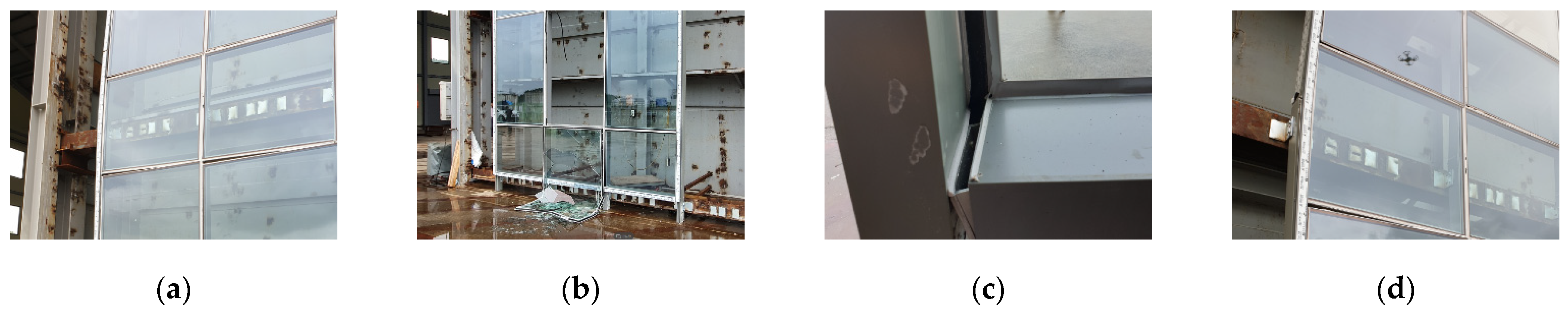
The examination results of the behavior of the curtain wall when applying the four levels of static displacement are as follows. When a displacement of 54 mm was applied, part of the weather sealant installed inside and outside of the curtain wall began to break, and the broken area and its range increased when a displacement of 72 mm was applied. It was confirmed that when the target displacement of this study, i.e., 150 mm, was applied, the glass was broken and fell due to residual deformation after the weather sealant was broken. Based on the test results, the main vulnerabilities of the curtain wall are summarized in Figure 4 and Table 3.
2.4. Expected Displacement Control Effects of Seismic Fasteners
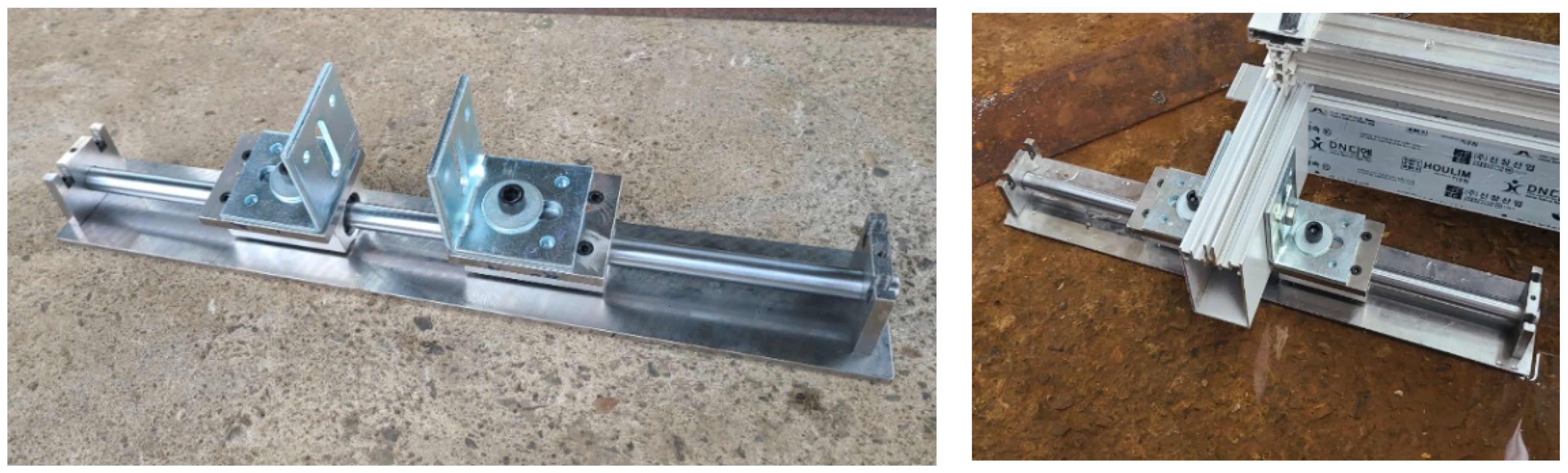
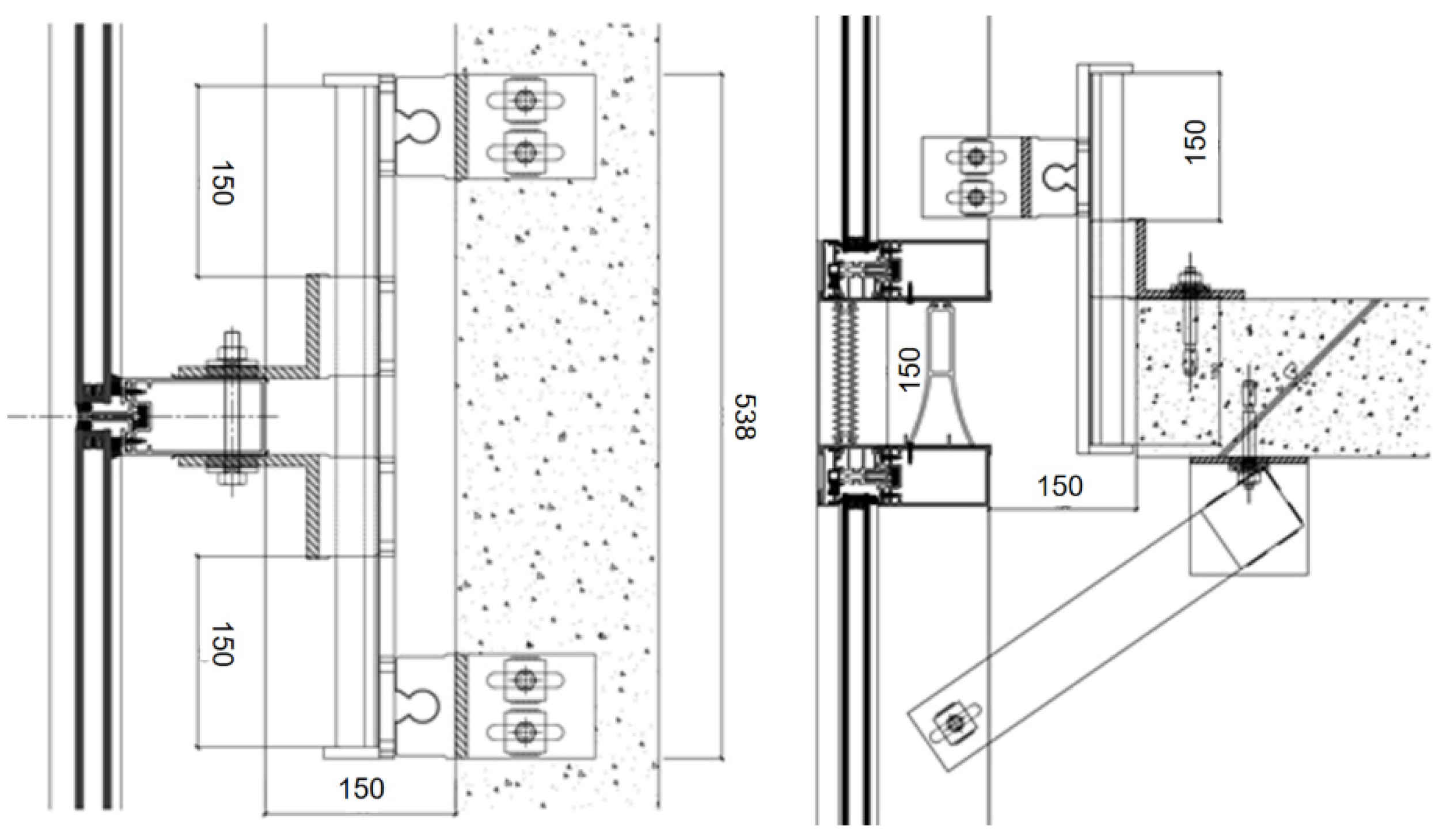
In general, the curtain wall structure constitutes a groove so that the glass can be inserted into the frame. Here, there is a movable clearance between the grooves in which the glass is fitted. The spacing of the clearance is between approximately 5 and 20 mm, depending on the type of curtain wall. With this clearance, it is possible to buffer in the left and right directions when an earthquake occurs. However, in the event of earthquakes, seismic performance up to 150 mm must be achieved, depending on the seismic grade. Through the static seismic performance assessment, it was confirmed that the conventional curtain wall was too weak to ensure structural stability in the event of earthquakes. However, because earthquakes result in dynamic behavior rather than static behavior, verification was required. In the AAMA 501.6 standard, the performance assessment is only considered in the X-axis in-plane direction in the representative dynamic seismic performance test method. However, because displacement can occur in three directions (X-, Y-, and Z-axis) when earthquakes occur, verification of all cases is required, and a curtain wall system capable of responding to movement in three axes is required. Accordingly, in this study, as shown in Figure 5, a curtain wall system was designed to control the displacement during earthquakes via the use of seismic fasteners that can withstand a maximum displacement of 150 mm and can cope with three-axis displacement. A cross-sectional drawing of the prototype design is shown in Figure 6.
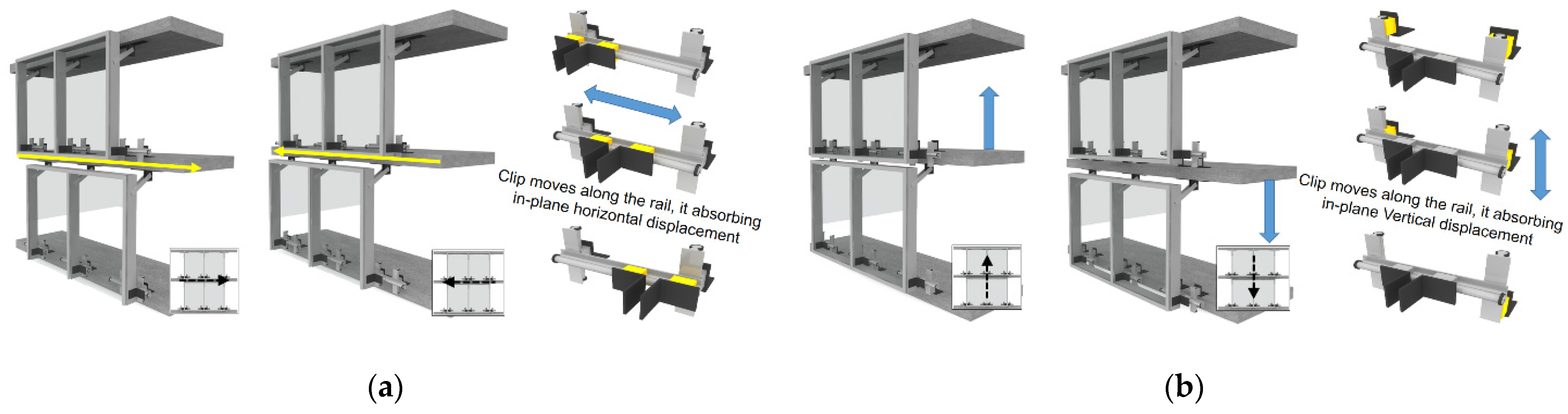
The design’s structure connects the lower part of the upper frame to the floor slab so that the vibration of the building generated by the external force caused by earthquakes is not transmitted to the curtain wall. Thus, the curtain wall can slide in the longitudinal and transversal directions of the building, as shown in Figure 7. In addition, it is composed of a movable clip and a rail that can move left and right (X-axis) or up and down (Z-axis). The structure can be fixed to the structure by bolting or welding, and was designed so that a displacement of up to 150 mm can be absorbed by the fastener.
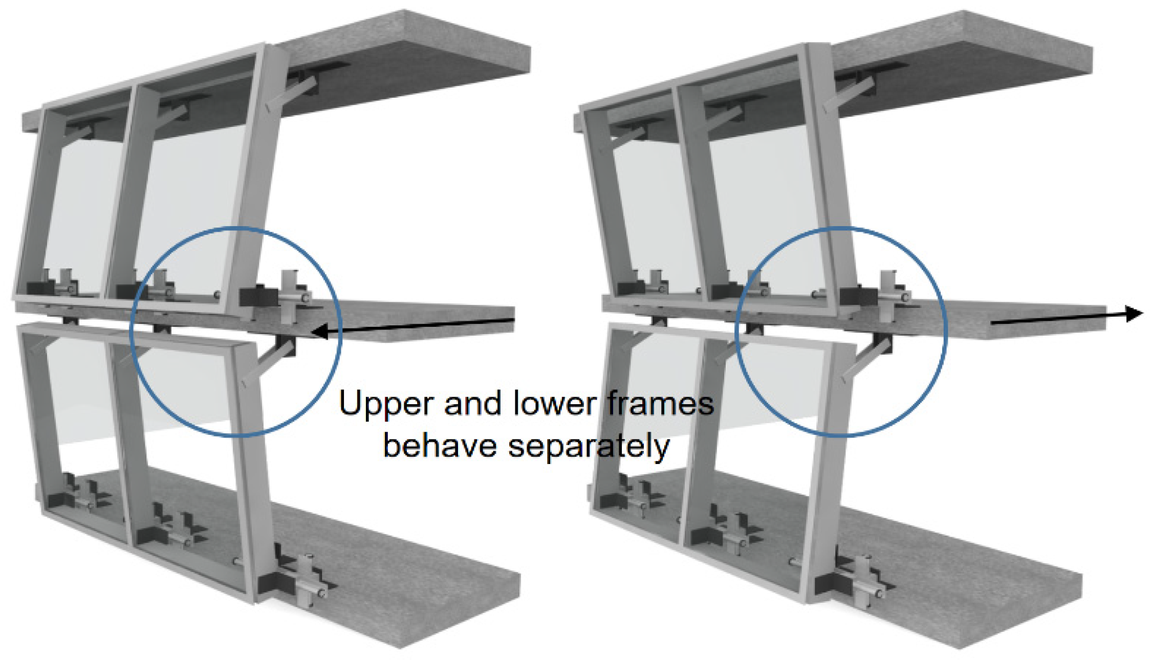
In addition, to cope with the displacement in the Y-axis direction, a separate inter-story module was applied, as shown in Figure 8, so that it can be operated separately without restraint between the upper and lower frames. As a result, it is free from stress concentration and buckling when displacement in the Y-axis direction occurs.
2.5. Dynamic Behavior of Curtain Walls: Description, Experimental Setup, and Results
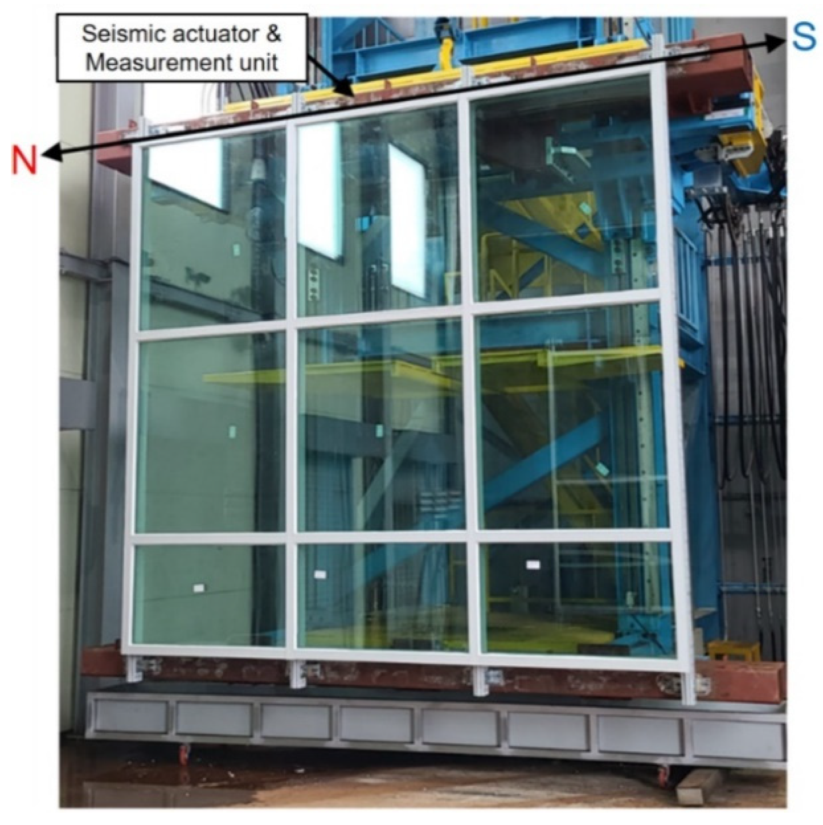
Currently, although the fastener design for three axes has been completed, the prototype is still in the production stage. Therefore, first, seismic fasteners that can respond only to the X-axis in-plane direction are currently manufactured. These fasteners can cope with a maximum displacement of 150 mm to the left and right. In this study, the dynamic seismic performance test, as shown in Figure 9, was performed based on the test method recommended by the AAMA 501.6 standard. In this test, the specimen fixes the upper and lower parts to the rigid beam, and only the rigid beam fixed to the upper part applies a dynamic displacement in the X-axis in-plane direction. A successful test of a particular curtain wall system assembly in which no glass fallout occurs, at the required percentage of drift, qualifies other assemblies, provided the following are satisfied by the other assemblies:
- (1)
- The components of the glazing system (e.g., setting blocks, side blocks, gaskets, silicone seals, etc.) are functionally the same;
- (2)
- The width and height of the glass lites do not exceed the tested size;
- (3)
- The nominal edge clearances are greater than or equal to those of the tested unit;
- (4)
- The percentage of inter-story drift is equal to or less than the tested unit;
- (5)
- The SSG bead contact width is equal to or wider than the tested unit;
- (6)
- The SSG bead thickness is equal to or thicker than the tested unit.
Therefore, in this study, only the performance assessment for the X-axis in-plane direction was considered. For the remaining axes, performance evaluation was performed using structural analysis in Section 4.
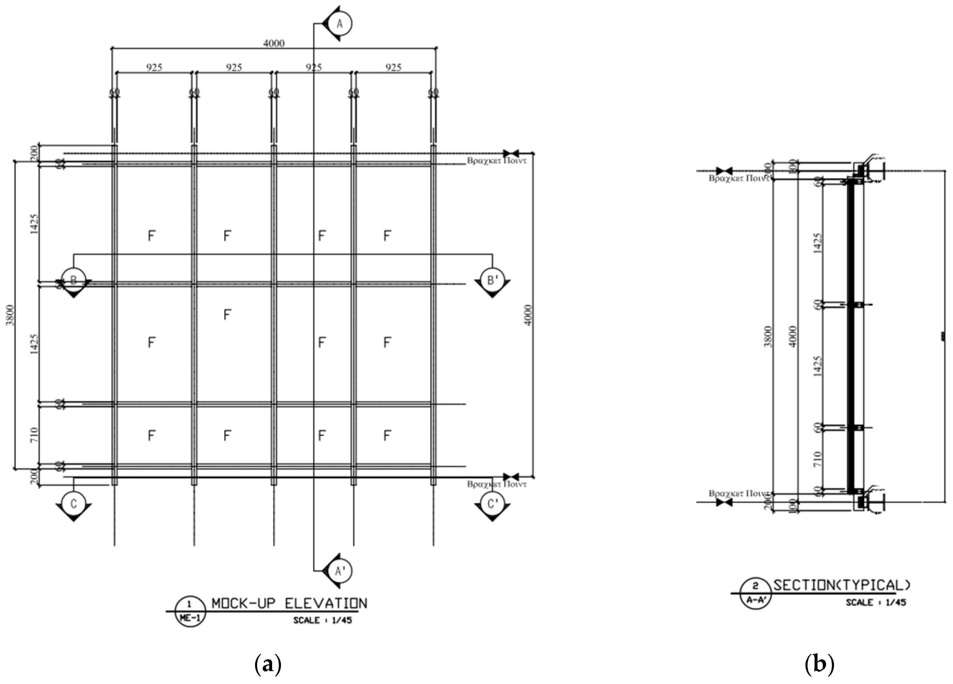
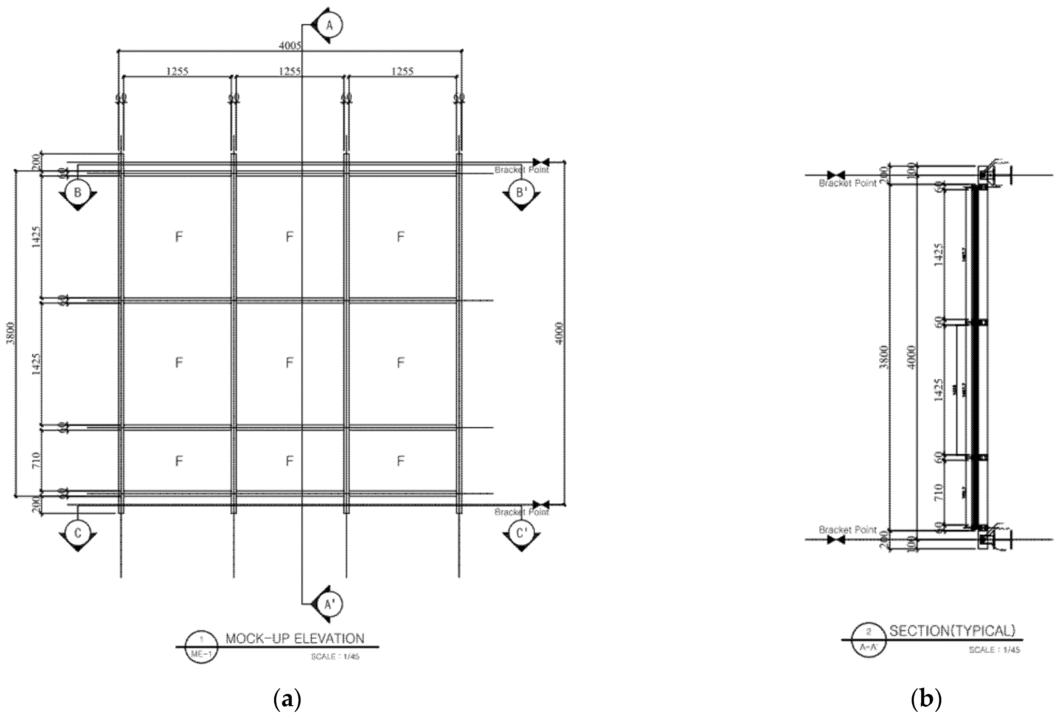
The dynamic seismic performance test was conducted on both non-seismic curtain walls, and seismic curtain walls to which mobile fasteners were applied, for comparison and analysis of the behavior of the curtain wall before and after the application of the seismic fastener. The detailed drawings and specifications of the non-seismic curtain wall specimen for the dynamic seismic performance test are shown in Figure 10 and Table 4, and the detailed drawings and specifications of the seismic curtain wall specimen are shown in Figure 11 and Table 5.
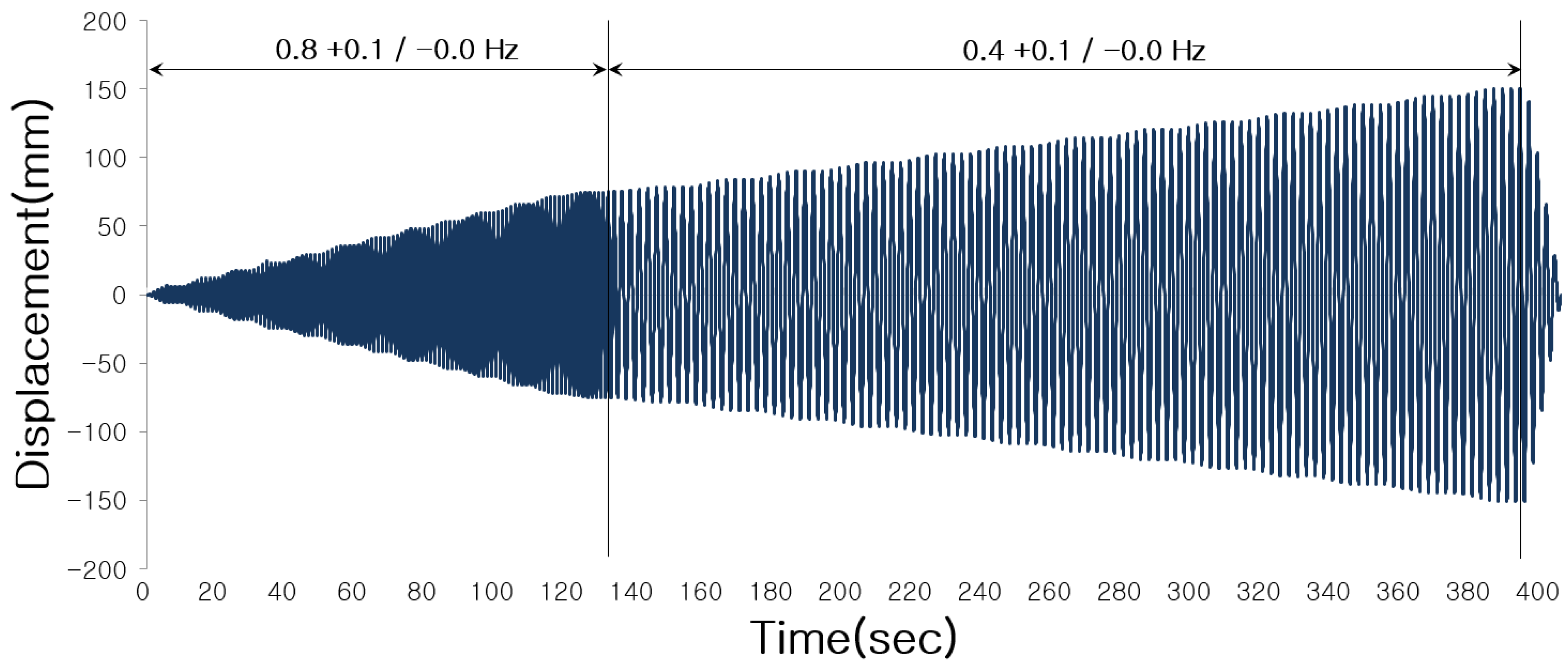
In the dynamic seismic performance test, a vibration of 0.8 Hz was applied up to the displacement of 75 mm, and vibration of 0.4 Hz was applied up to the displacement of 150 mm, as shown in Figure 12, according to the AAMA 501.6 standard. The test was conducted while gradually increasing the displacement by four cycles at intervals of 6 mm.
Table 6 compares the results of the dynamic behavior analysis after the dynamic racking crescendo test for non-seismic and seismic curtain walls. ΔFallout is an essential requirement, ΔSeal cracking and ΔCracking are considered to be optional.
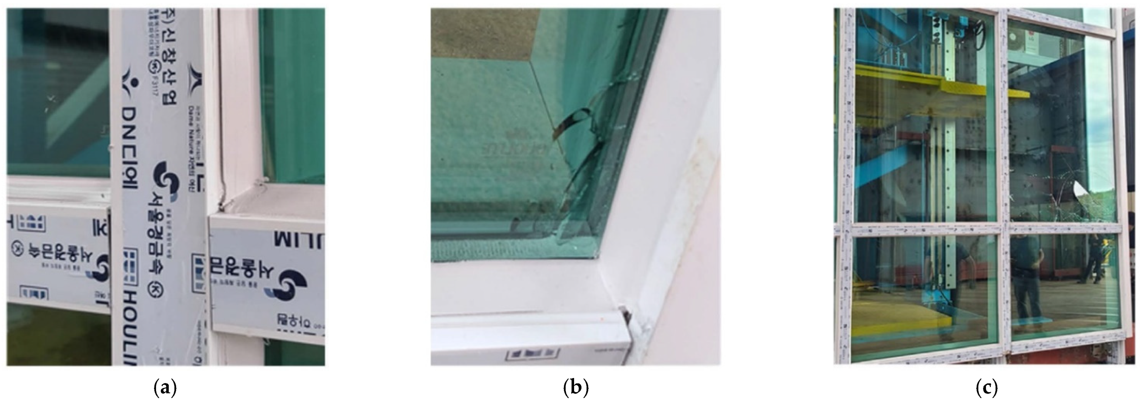
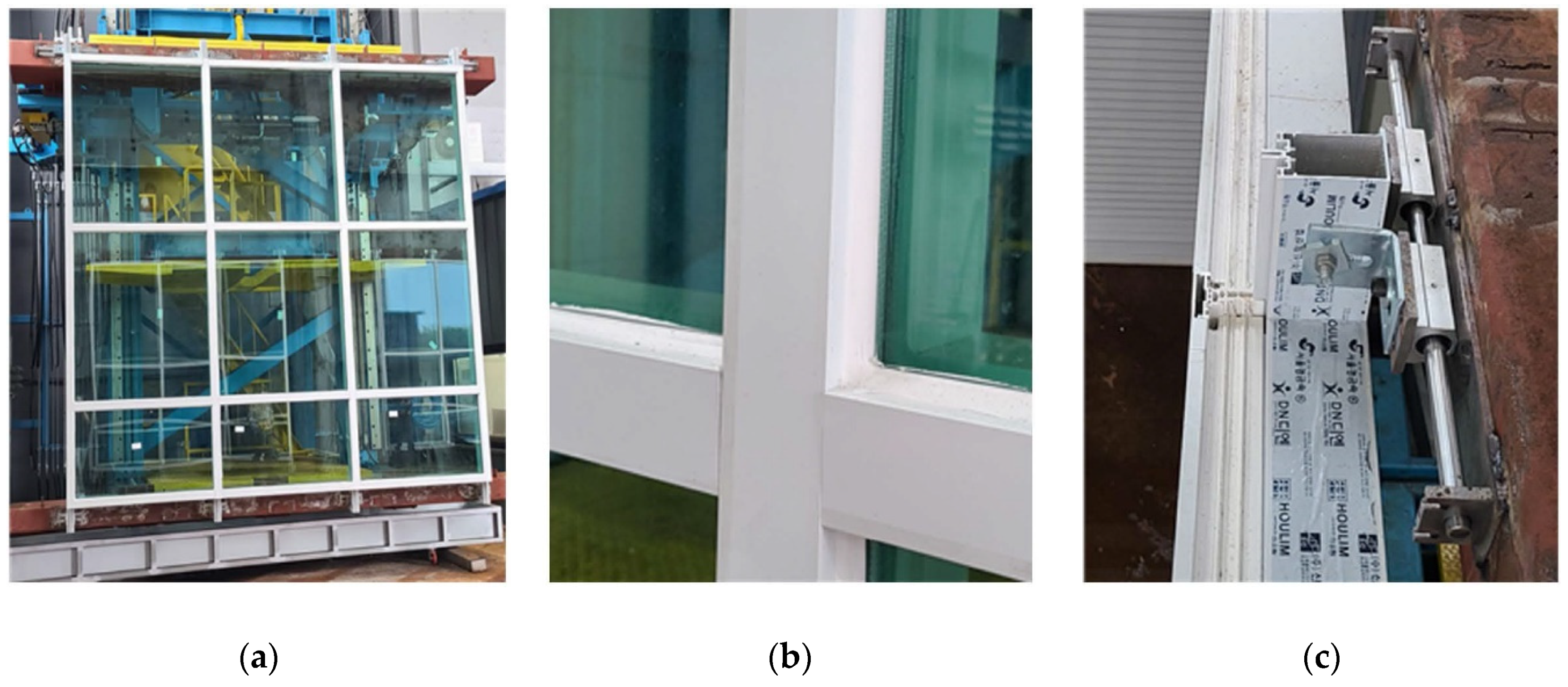
In the case of the non-seismic curtain wall test specimen, it was confirmed that the glass fallout occurred at a displacement of 90 mm due to severe damage to some members, as shown in Figure 13, in the static seismic performance test. However, in the case of the seismic curtain wall to which the mobile fastener was applied, no cracks, breakage, or fallout occurred in the entire frame following the test, as shown in Figure 14, and the upper fastener to which the dynamic displacement was applied had no abnormality.
The comprehensive assessment of the results of the dynamic seismic performance test showed that due to the application of a fastener with a displacement control function, even if a dynamic racking crescendo is applied to the curtain wall, the wall can respond to earthquakes with a displacement of up to 150 mm, which is 3.75% of the floor height, thus ensuring the seismic performance.
3. Finite Element Method (FEM): Seismic Performance of Curtain Wall
For the optimal design of fasteners to reinforce the seismic performance of the curtain wall, and to reliably predict the seismic behavior of the curtain wall and verify the seismic reinforcement effect, it is necessary to develop a numerical model of such a system. The feasibility and potential of the proposed mobile fastener are assessed in this section via FE numerical analysis carried out in ABAQUS.
For this purpose, simulations were performed at the level of the full-frame curtain wall modeled at a 1:1 scale, which was the same as that of the large-scale experiments. Simulations were also performed for single-frame curtain wall components to verify the seismic reinforced performance of the curtain wall with the proposed fastener and provide evidence of its benefits and critical aspects.
3.1. FE Modelling of the Full-Frame Curtain Walls
The purpose of this section is to develop numerical models of various curtain wall elements for accurate experimental and finite element analyses. To ensure accuracy, the analyses focus on the global behavior of the curtain wall and the reaction to the external forces.
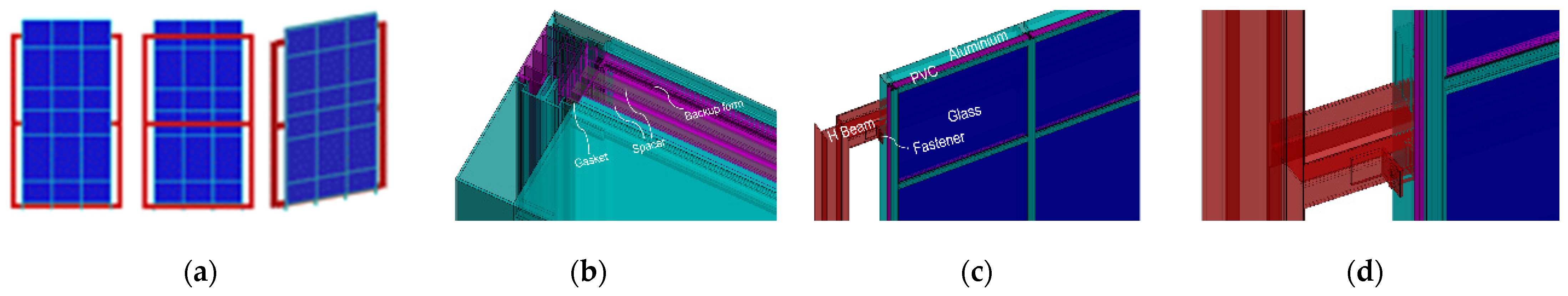
A finite element model was constructed and implemented using the ABAQUS program to predict the seismic behavior of the stick curtain wall. The FE model was performed at the same 1:1 scale as the specimen used in the previous seismic test. The material used for the numerical analysis was the same as the seismic test specimen, and its properties are shown in Table 7. The properties of rubber were applied by inputting values calculated based on the test data, and for other materials, generally used properties were applied. Figure 15 shows the details of the solid-form FE model constructed in 3D.
All materials were assumed to be constrained to behave within their elastic range. Glass is a brittle material and failure occurs when the deformation state reaches its limit. The stress level of aluminum is significantly lower than the strength of the material, so ductile deformation does not occur. Therefore, it is reasonable to limit the use of the elasticity theory. Nonlinear static analysis was performed on the behavior of the curtain wall under displacement control. The curtain wall model was displaced to produce the specified movements. When displacement is applied, it should consist of three full cycles. (Herein, a cycle is defined as a full displacement in one direction back to the originating point, full displacement in the opposite direction, and return to the originating point.) The horizontal displacement was applied to the mullion connected to the rigid beam located in the middle of the main structure, and the inter-story drift was calculated.
The boundary condition was set by fixing the vertical and horizontal displacements of the nodes at the connection between the aluminum frame and the fastener located at the top and bottom.
3.2. FE Modelling of the Single-Frame Curtain Walls
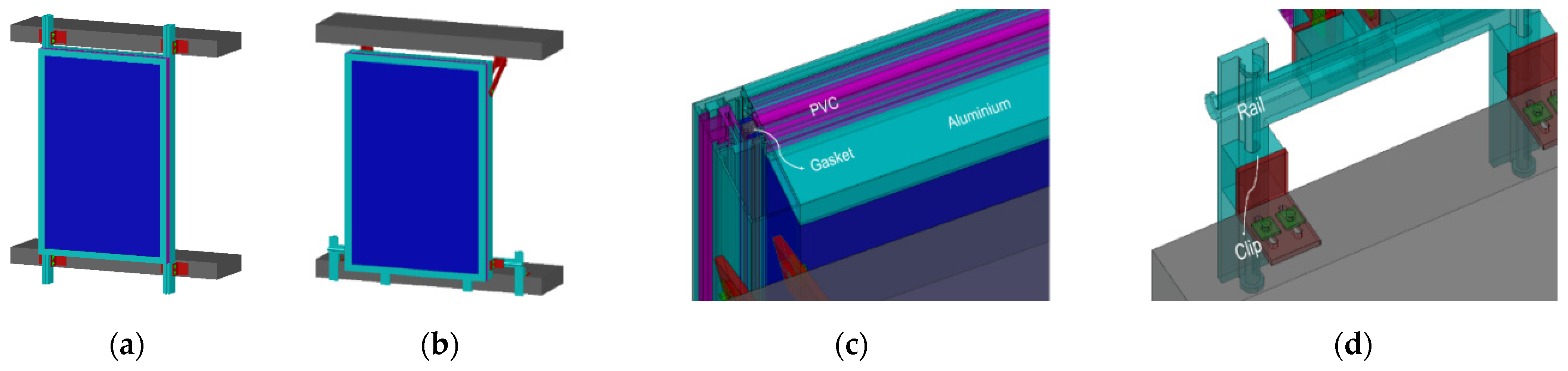
Based on the results of the FE analysis for the full-frame curtain wall discussed in Section 3.3, additional FE simulations were performed on numerical models that well represent the nominal components and interactions of the single-frame curtain wall. All components comprising the curtain wall were applied as noted in Section 3.1, and their material properties were also the same. However, unlike the full-frame, in the case of the single-frame model, boundary conditions were set by restraining the horizontal and vertical displacement of the aluminum frame connected to the lower rigid beam, whereas the upper rigid beam was set as the free end. Figure 16 shows the details of the FE model constructed for a single-frame curtain wall.
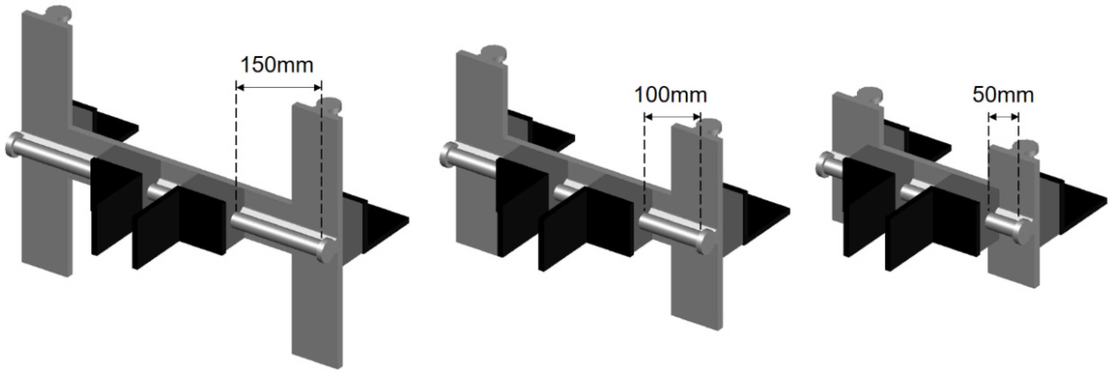
For the single-frame curtain wall, seismic performance numerical analysis was performed based on the method according to AAMA 5014 and AAMA 501.6 standards. Dynamic seismic performance was analyzed by calculating the distribution of the stress received by each member of the curtain wall after applying displacement to the curtain wall model with the crescendo waveform provided in AAMA 501.6. In particular, when performing numerical analysis of dynamic seismic performance, modeling was undertaken by dividing the length of the linear guide into 50, 100, and 150 mm among the components of the mobile fastener, as shown in Figure 17. This was undertaken to analyze the seismic performance of the mobile fastener according to the change in the length of the linear guide.
3.3. Static Seismic Analysis of Curtain Wall by AAMA 501.4 Standard
To assess the structural performance of the curtain wall subjected to simulated static displacements based on the AAMA 501.4 standard, first, static seismic analysis was performed in the lateral (X-axis) direction for the full-frame curtain wall. The displacement applied to the entire frame curtain wall was set to connect the rigid beam and the aluminum frame using the same method as that used in the seismic test, and to impose a static displacement in the horizontal (X-axis) direction to the middle rigid beam; the peak displacement was 150 mm.
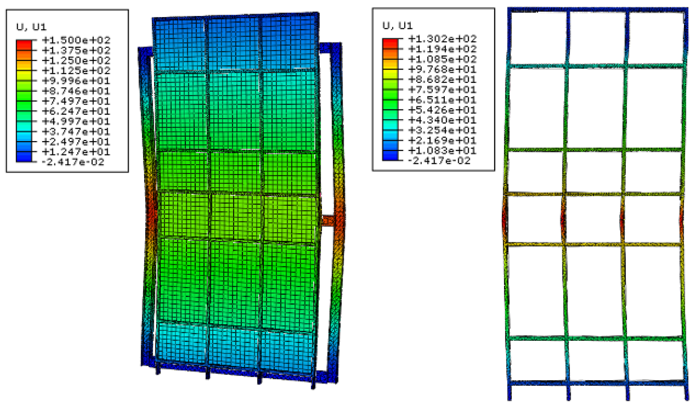
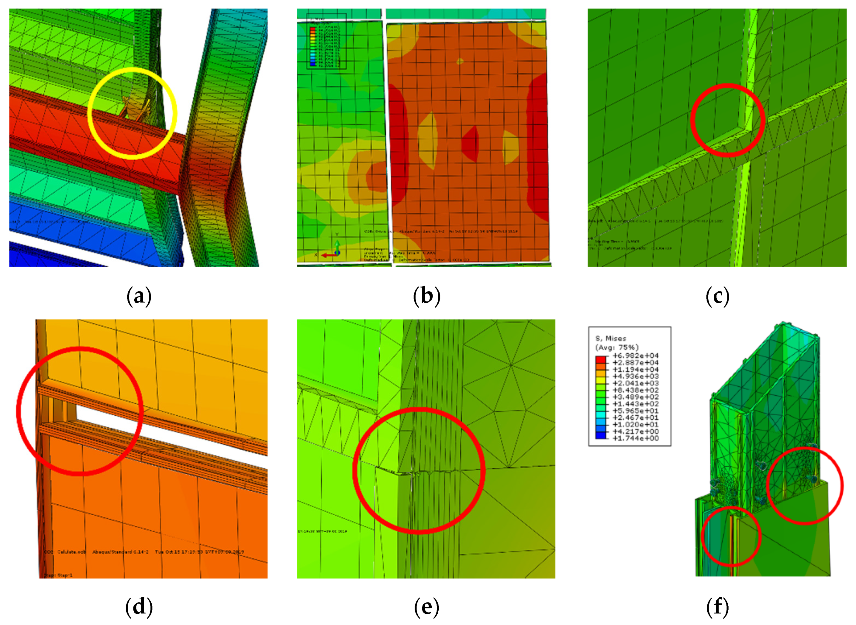
The deformation when 150 mm of static lateral displacement was applied to the full-frame curtain wall is shown in Figure 18. Table 8 shows the major vulnerabilities of the full-frame curtain wall derived after performing the FE simulation. In particular, the gasket, which is a super-elastic material that restrains the glass façade, incurred a separation from the frame while applying a drift that exceeds the clearance. This indicates that the glass façade may break and fallout may occur. The vulnerabilities of the conventional curtain wall confirmed through the FE simulation showed similar results to the vulnerabilities confirmed through the experiment, as shown in Figure 19.
Based on the FE simulation of the full-frame curtain wall, it was confirmed that the numerical model normally operates similarly to the static seismic experiment. However, it is essential to review each of the three axis (X-, Y-, and Z-axis) directions. To accurately analyze the interaction between the members constituting the curtain wall when it behaves due to earthquakes, FE simulations were performed on the single-frame numerical model composed of the largest glass façade.
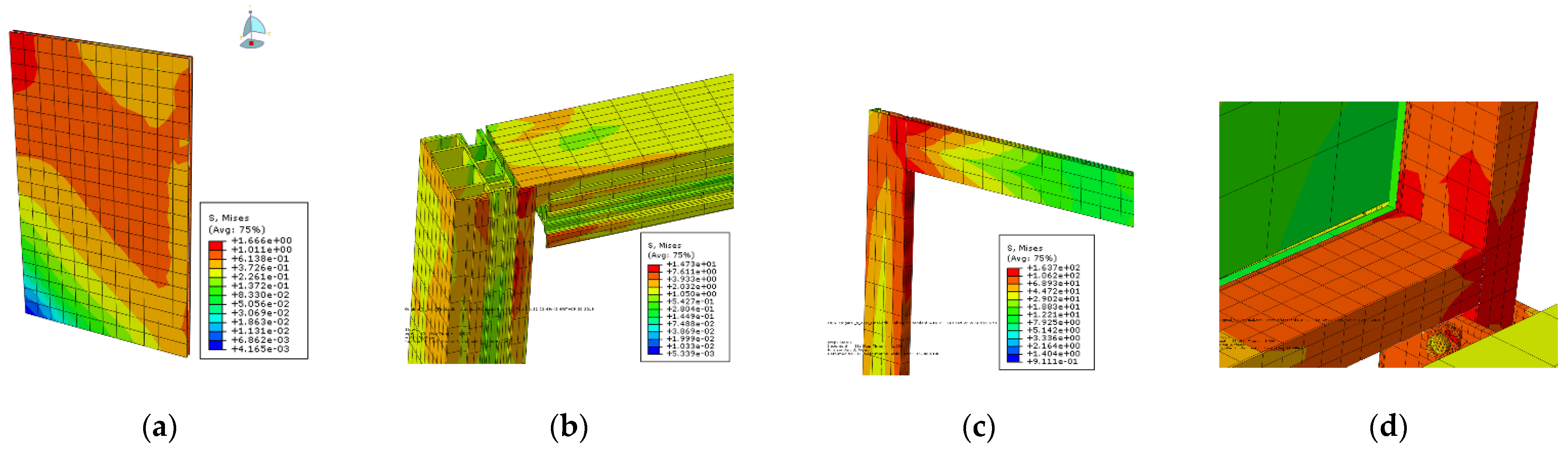
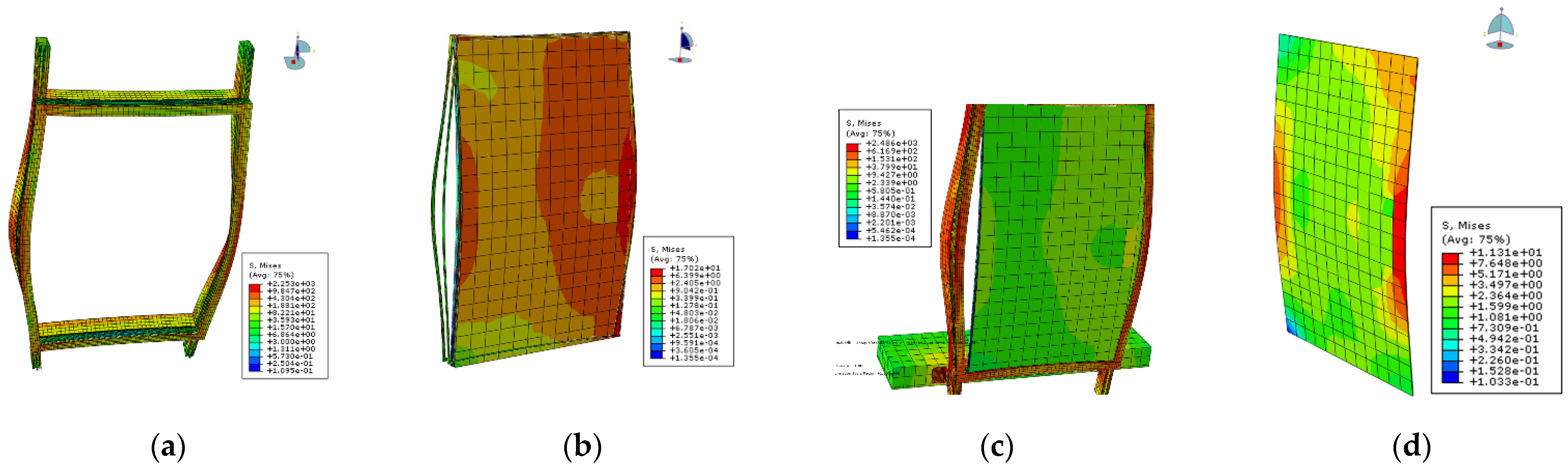
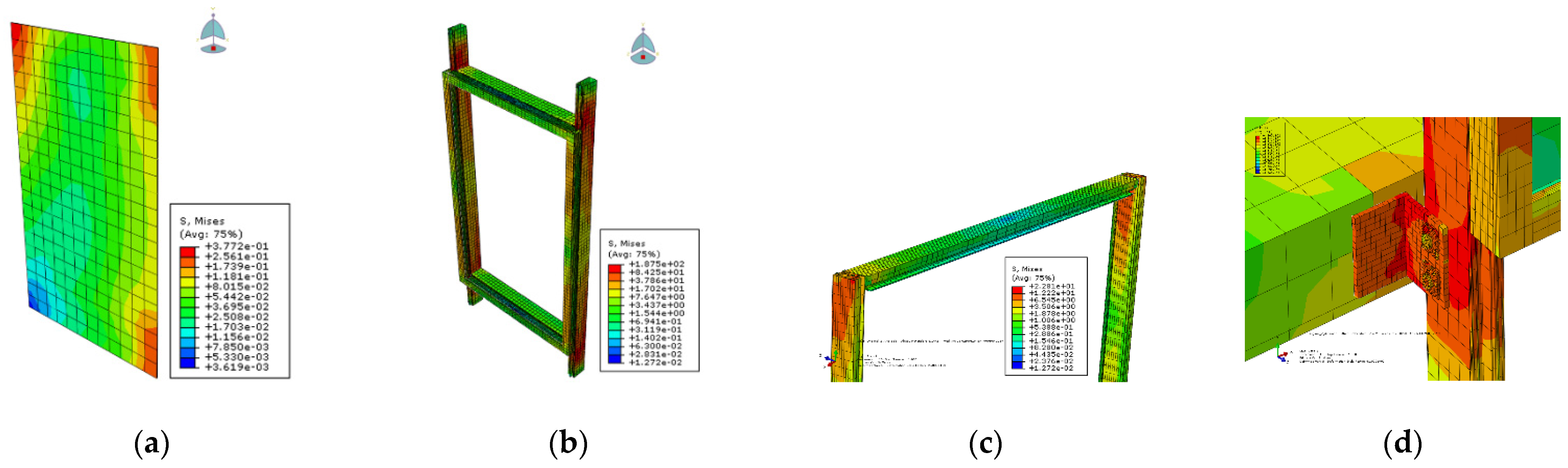
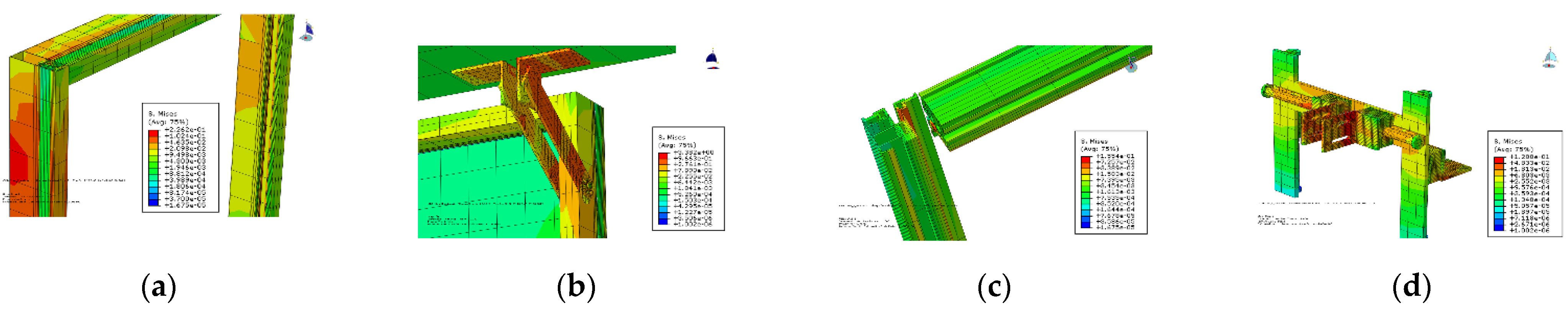
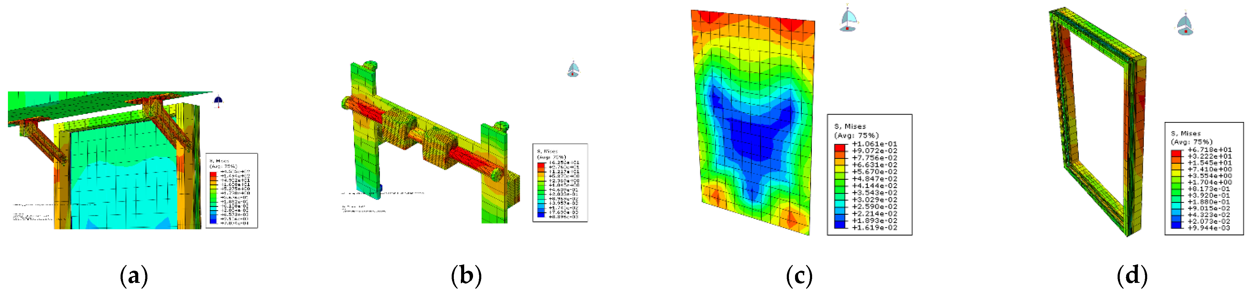
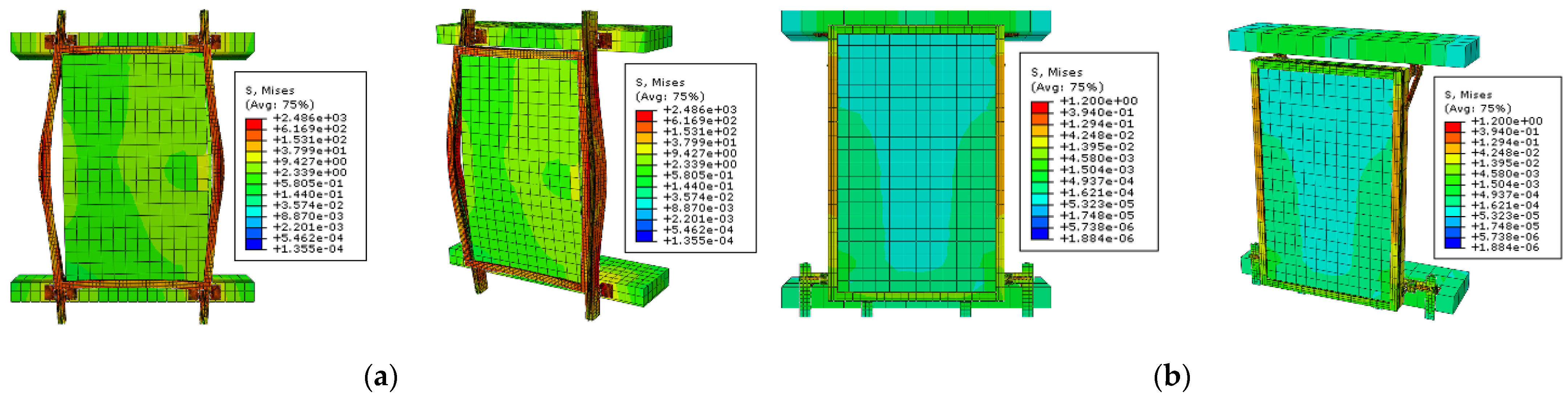
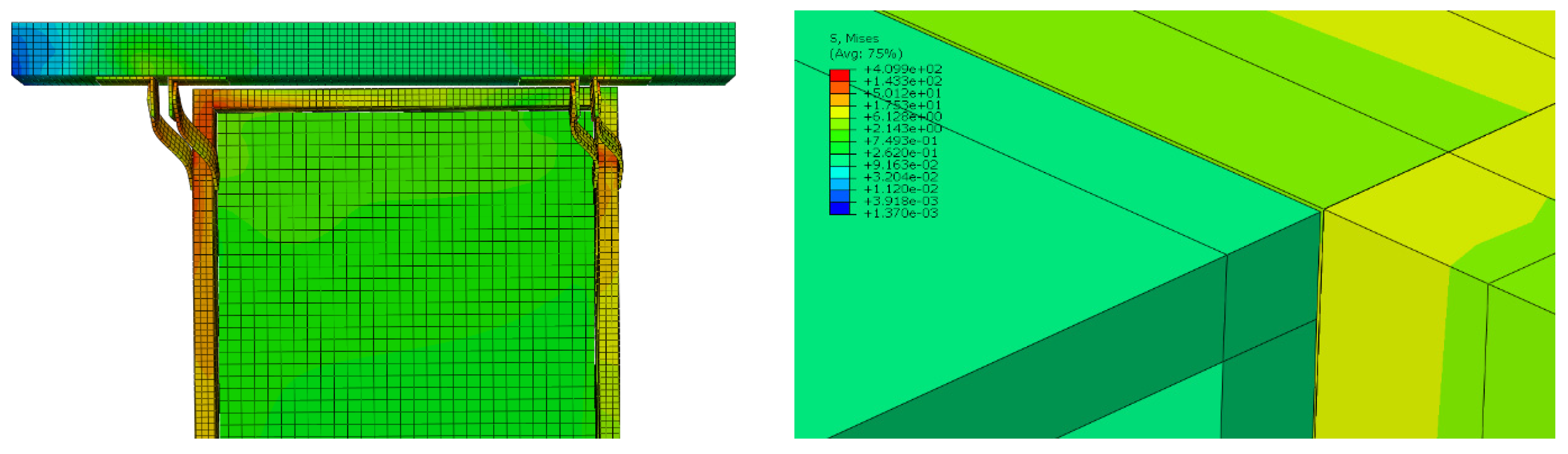
To compare the seismic performance of the non-seismic curtain wall and the curtain wall, the load on a single frame was set to apply a 50 mm displacement along the three axes (X-, Y-, and Z-axis). The aluminum frame and rigid beam were fixed by fasteners. Then, a lateral static displacement was applied to the upper rigid beam. Figure 20, Figure 21, Figure 22, Figure 23, Figure 24 and Figure 25 show the stress distribution applied to the curtain wall during static drift in the three axis directions through FE simulation. The stress distribution was calculated using the Von Mises principle.
Through FE analysis of the stress distribution applied to the non-seismic curtain wall that was subjected to simulated static displacements based on the AAMA 501.4 standard, it was confirmed that the yielding of the gasket caused the sliding trigger between the glass façade and the aluminum frame. That is, it was predicted that glass-to-frame collision occurs as the aluminum frame deforms and the gasket is distorted, which ultimately causes the glass façade to fall out.
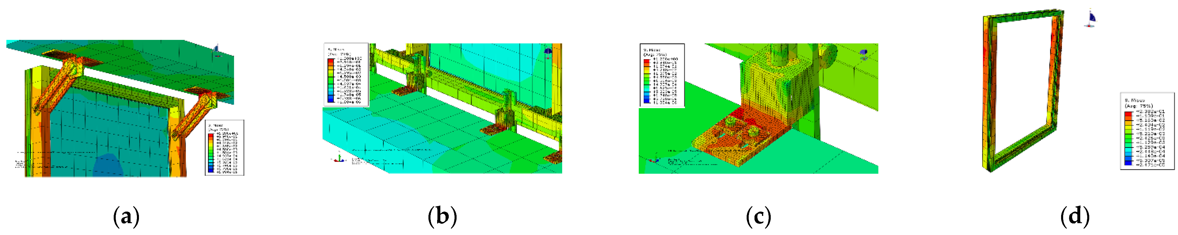
However, in the case of a seismic curtain wall to which the fastener model proposed in this study is applied, which can control the displacement up to a maximum displacement of 150 mm, it is possible to adapt to changes in the geometry of the curtain wall system and the inter-story drift. It was confirmed that there was no damage in the event of earthquakes because the displacement applied to the curtain wall through the proposed fastener was dissipated and the stress was not transmitted to other members.
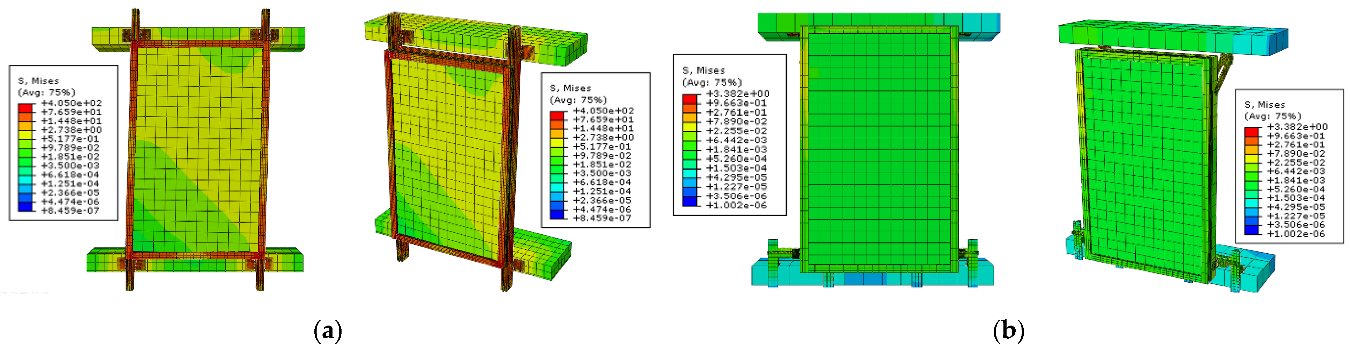
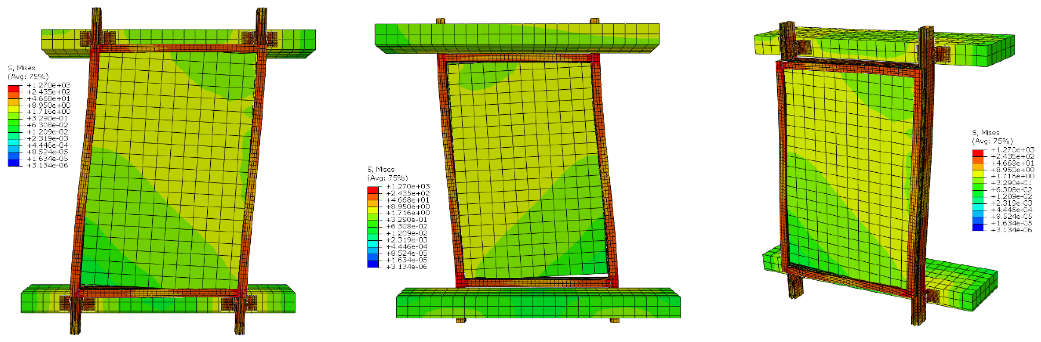
As can be seen in Table 9, it was confirmed that the stress in the maximum drift of the seismic curtain wall was significantly reduced in all axes, except the Z-axis, compared to the non-seismic curtain wall. In the case of the non-seismic curtain wall model, because it is a monolithic structure, if inter-story drift occurs, it is transferred from the main structure to the exterior material, and the stress between adjacent members is concentrated. By comparison, in the seismic curtain wall model, it was confirmed that the inter-story drift generated in the X-axis and Z-axis is dissipated through the mobile fastener, and the stress at the maximum drift is significantly reduced to 3.38 MPa in the X-axis and 1.2 MPa in the Z-axis. Figure 26, Figure 27 and Figure 28 show the comparison of changes in the appearance of non-seismic and seismic curtain walls when maximum inter-story drift is applied.
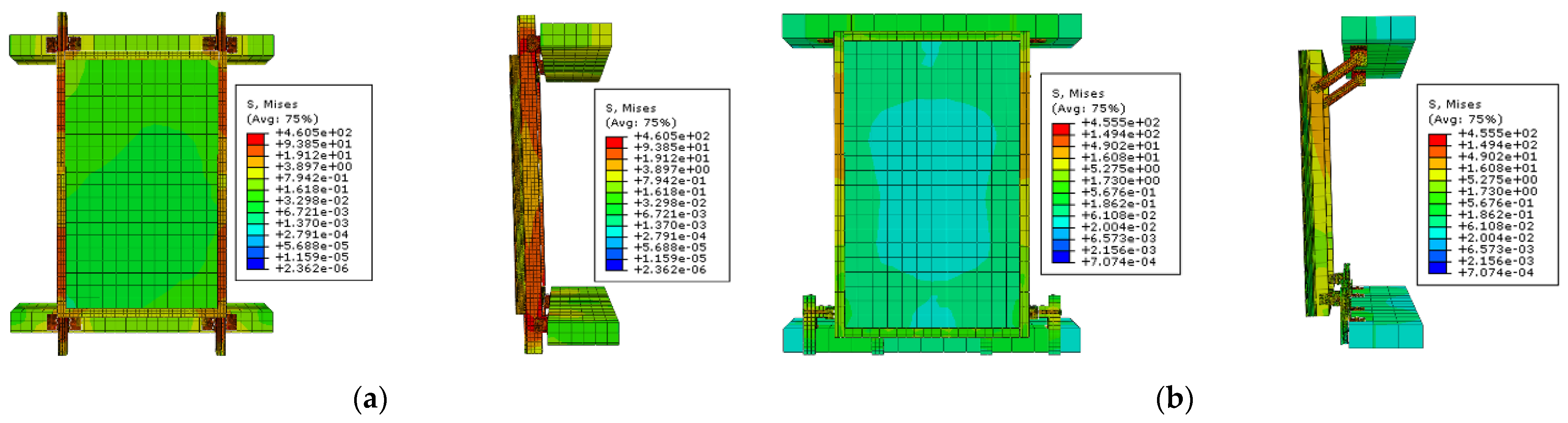
The stress at the maximum drift of the non-seismic curtain wall and seismic curtain wall when inter-story drift is applied in the Y-axis shows similar values. However, in the case of a seismic curtain wall, as described in Section 2.4, because a separated inter-story module is installed between the upper and lower frames, the drift is not transmitted directly from the main structure to the exterior material. Thus, the calculated stress is theoretically meaningless. Therefore, to summarize the analysis results through FE simulation, even if an inter-story drift occurs in the structure, the problem of conventional curtain walls can be completely solved because the drift can be dissipated by applying the fastener with displacement-absorbing performance proposed in this study. As a result, the seismic performance of the proposed curtain wall system against static displacements was verified.
3.4. Dynamic Seismic Analysis of Curtain Wall by AAMA 501.6 Standard
Based on the previous single-frame curtain wall static analysis, the results of the numerical analysis on the X-axis ensure the validity of the numerical analysis on the remaining axes. Therefore, the dynamic seismic performance assessment in this study was conducted mainly on numerical analysis in the X-axis direction. Structural performance was predicted and evaluated when dynamic displacement simulating the AAMA 501.6 seismic waveform was applied to the lateral axis (X-axis). The authors intended to verify whether the vulnerabilities that occur in the non-seismic curtain wall system when dynamic drift occurs can be compensated by using mobile fasteners and inter-story separated modules by comparatively analyzing the seismic performance according to the structural analysis results.
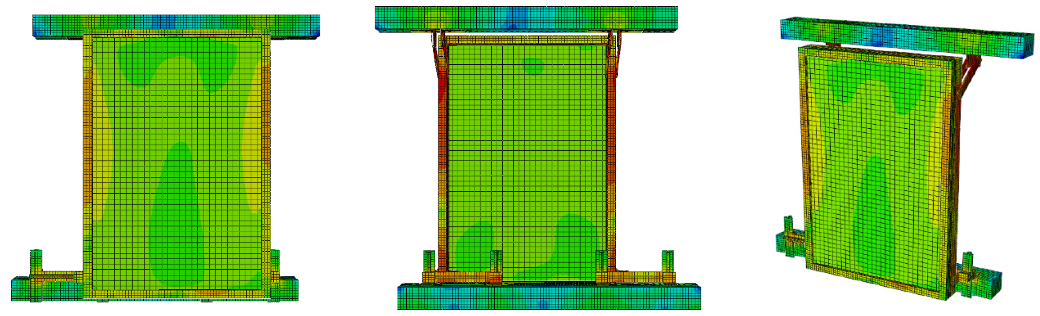
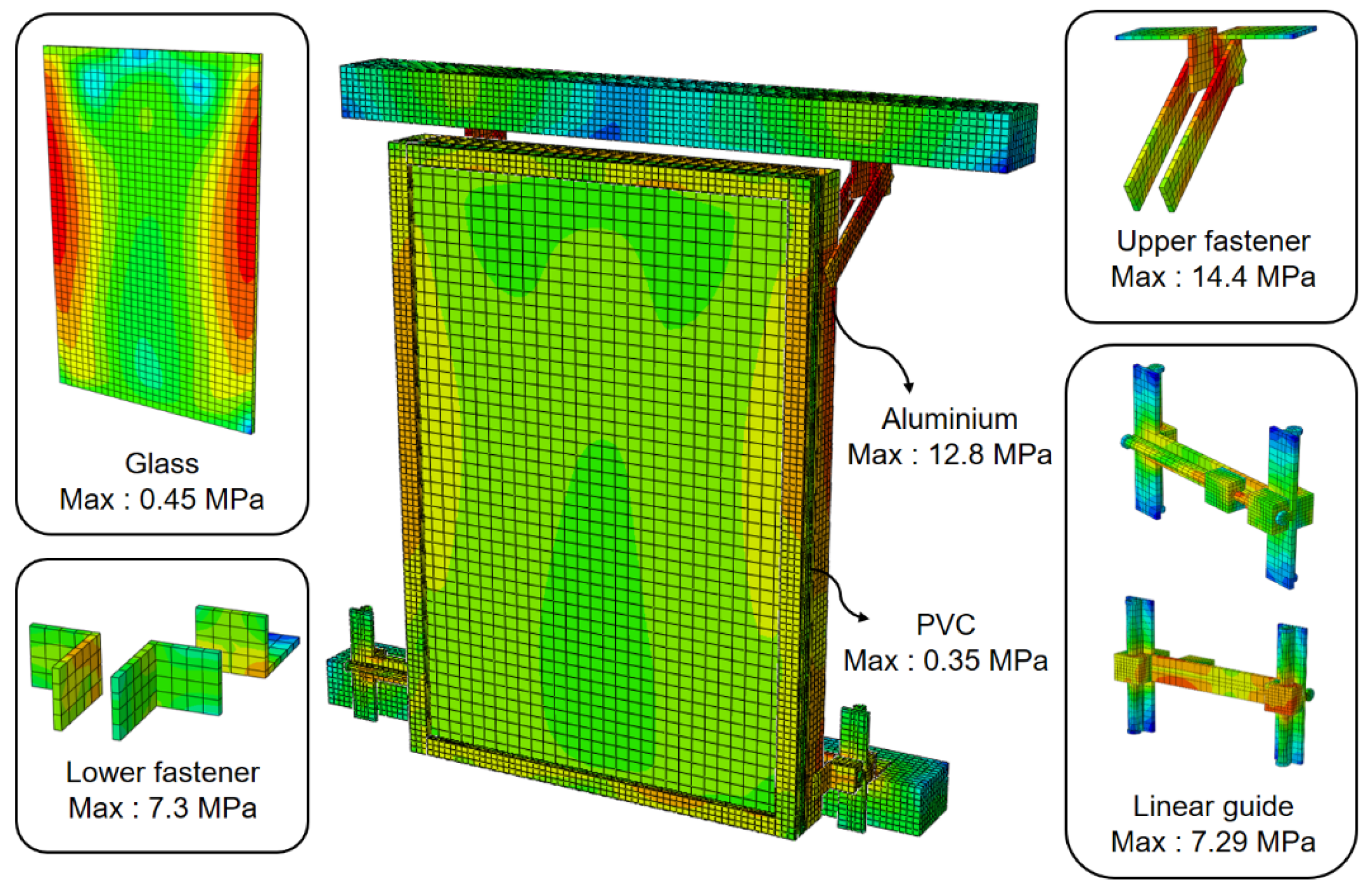
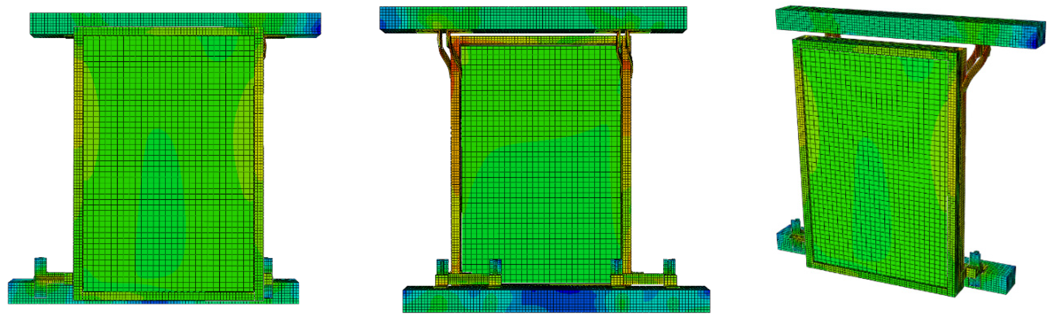
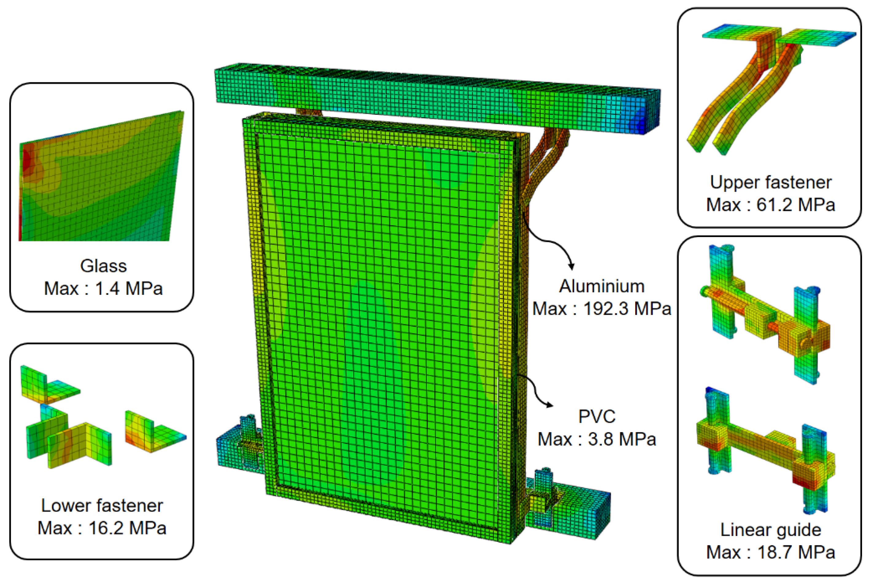
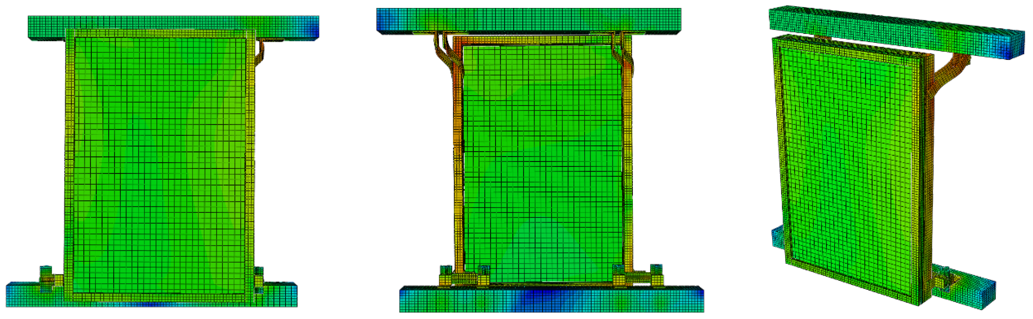
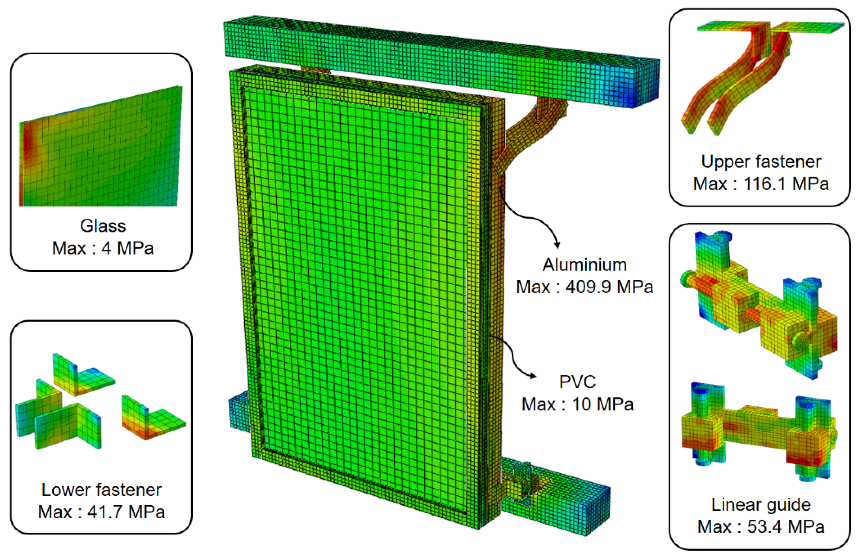
In addition, to minimize the length of the linear guide, numerical models were additionally created in which the length of the linear guide was reduced to 100 and 50 mm based on the 150 mm, which is the basic shape of the curtain wall module introduced in the previous section. Then, according to the AAMA 501.6 standard, the behavior and seismic performance of the curtain wall according to the decrease in the linear guide length under dynamic drift were compared. Figure 29, Figure 30, Figure 31, Figure 32, Figure 33 and Figure 34 show the results of finite element analysis, and compare the Von Mises stress distribution and the degree of deformation of the exterior material according to the linear guide length when AAMA 501.6 dynamic drift was applied.
Table 10 shows the maximum stress generated in each member. According to the FE analysis results, it was found that the stress distribution in each member was greatest in the mullion when the dynamic drift was applied. When dynamic drift was applied, the displacement could be controlled because the moving clip of the linear guide moves along the rail in the axial direction in which the drift is applied. Based on this principle, the stress applied to the exterior material is absorbed and dissipated.
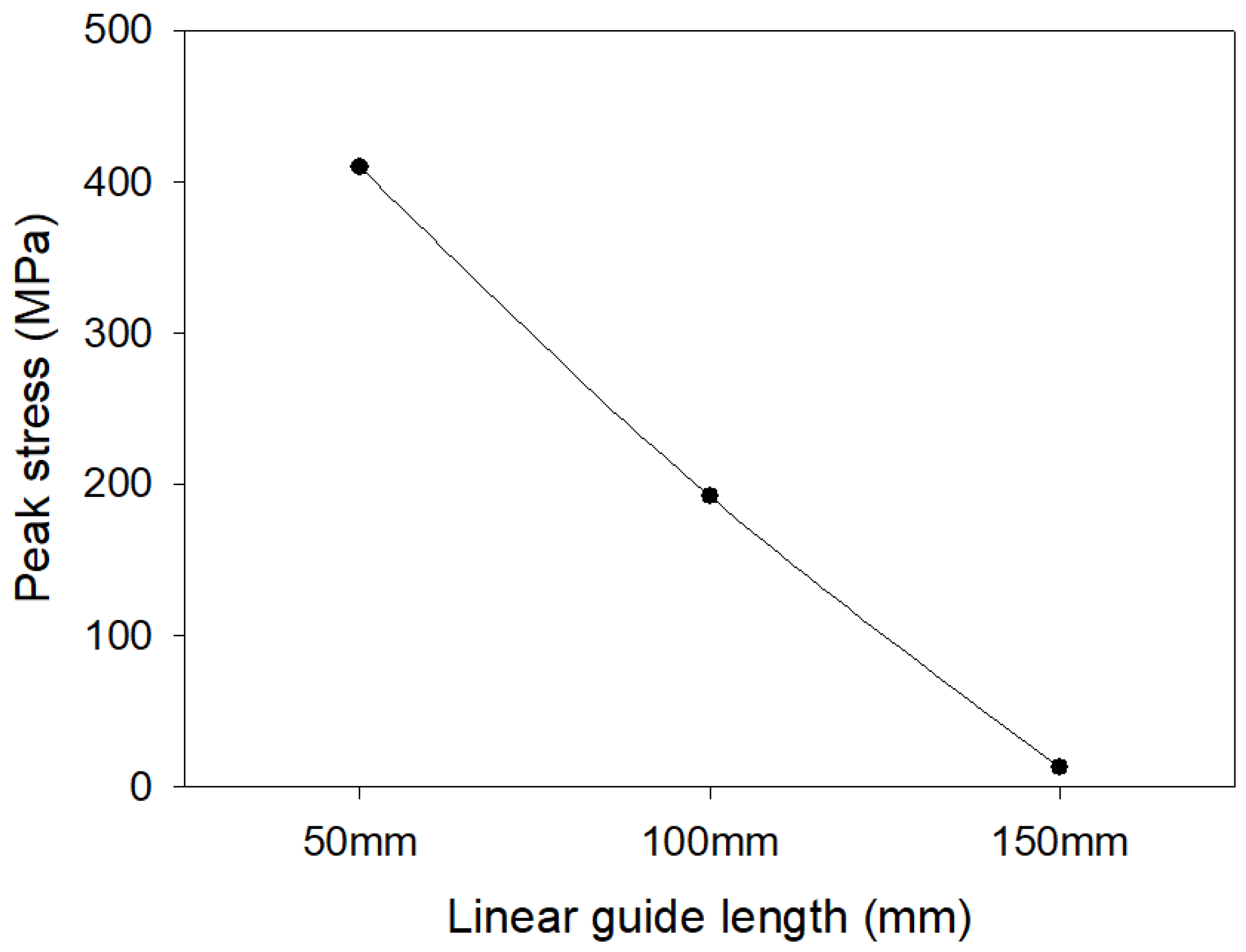
The results according to the change in the length of the linear guide show there were no partial dropouts and breakages of each member as a whole. As the displacement absorption section decreased to 100 and 50 mm based on 150 mm, the stress applied to the curtain wall gradually increased. It was found that the stress increased linearly with the decrease in the length of the displacement absorption section, which is shown in Figure 35. When the length of the linear guide was reduced to 50 mm, there was no damage to the glass façade, as shown in Figure 36, but as the displacement increased, the upper fastener was deformed, and a slight gap was found in the member junction between aluminum and PVC. However, compared with the deformation of the non-seismic curtain wall shown in Figure 37, it was judged that even if the length of the linear guide is reduced to 50 mm, it has sufficient seismic performance in response to dynamic seismic waves.
Through the comparative analysis of the stress distribution between the non-seismic curtain wall and the seismic curtain wall summarized in Table 11, it was confirmed that the problem of the non-seismic curtain wall could be completely compensated for and structural stability could be ensured by applying the mobile fastener when a dynamic seismic wave occurred.
4. Usability Performance Assessment of Seismic Curtain Wall
4.1. Test Overview for Heat Insulation and Airtightness Performance Assessment
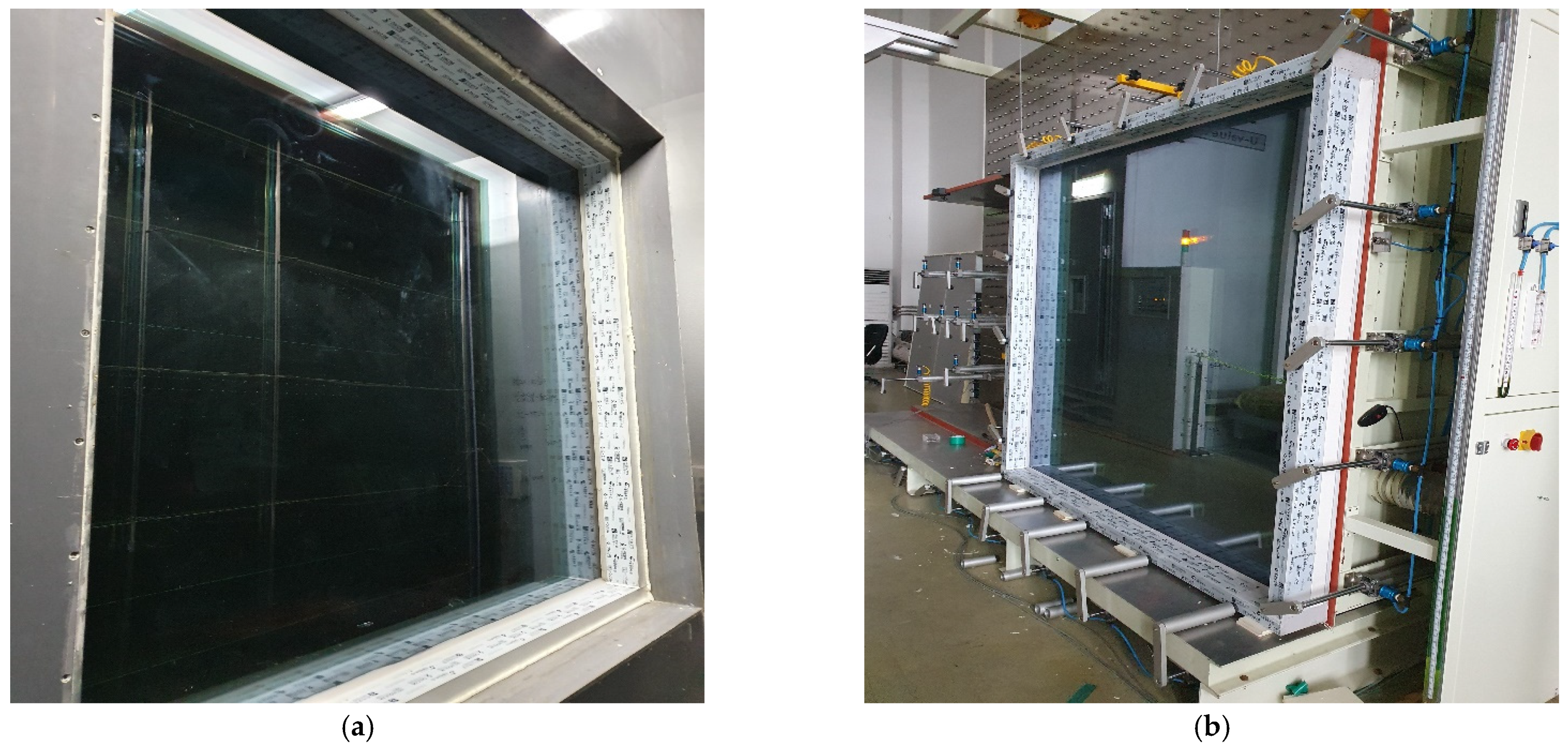
Because energy regulations for buildings have recently been strengthened, the development of curtain walls with high insulation and airtightness is required [32,33]. Although this study focused on securing seismic performance, for final commercialization it is necessary to develop a curtain wall with window set energy efficiency grade 1 (heat transmission rate of 1.0 W/m2 K or less, airtightness grade 1 or higher). In this study, the thermal insulation performance was predicted through two-dimensional heat transfer analysis, and the high insulation curtain wall design was conducted accordingly. The sample specifications for evaluating the insulation performance of the seismic curtain wall are shown in Table 12. The frame material is aluminum, and the sample was produced with the same 175 mm curtain wall frame as that of the seismic curtain wall. For the glass specification, 42 mm triple glass was applied, and the spacer was used as a synthetic resin insulating inter-story. The insulation and airtightness performance evaluation setup is shown in Figure 38.
4.2. Test Overview for Watertightness and Wind Pressure Performance Assessment
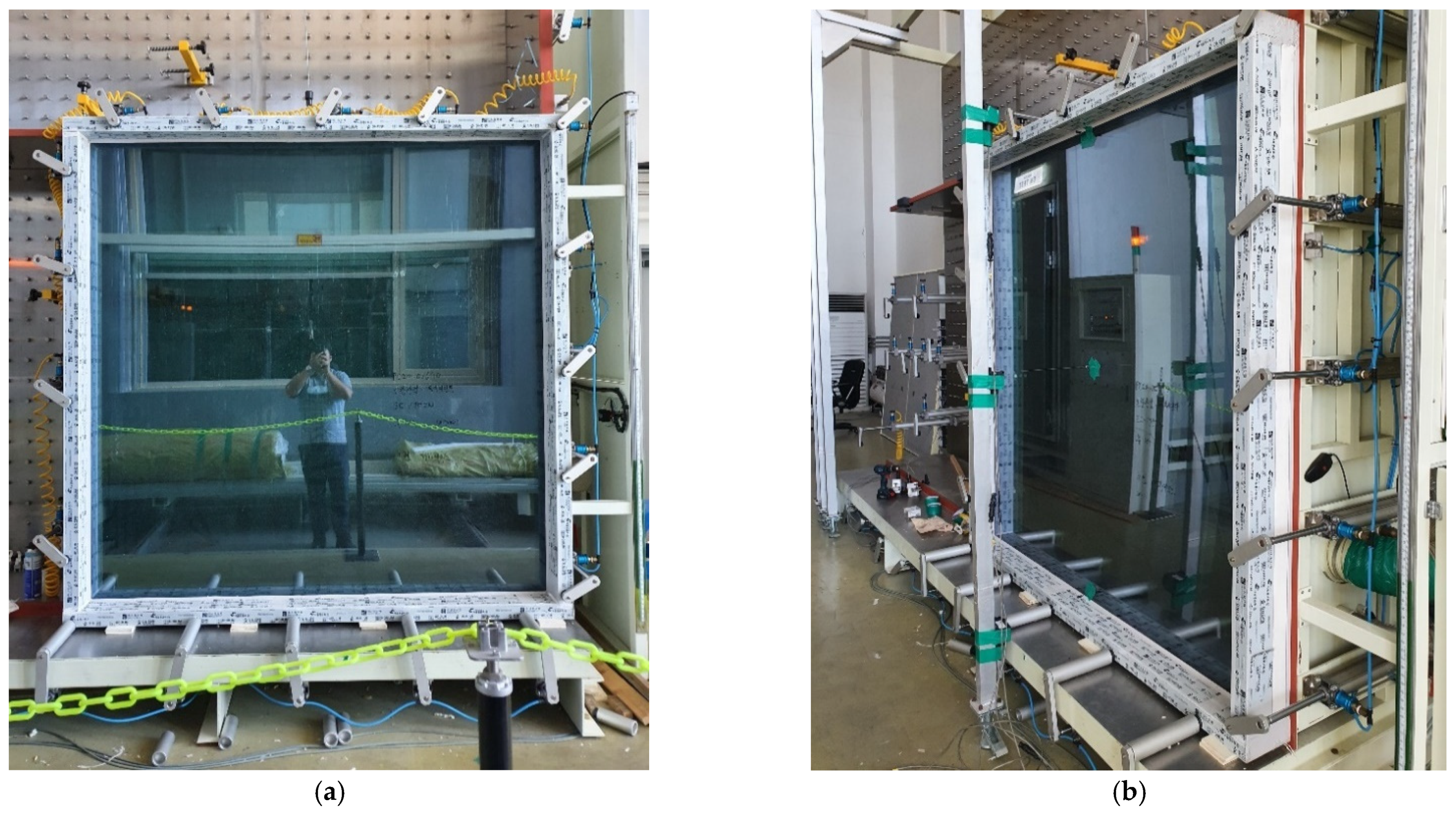
If watertightness is not achieved in terms of the usability of the curtain wall, it may result in a defect. Thus, performance must be ensured. In addition, curtain walls must be designed so that glass is not damaged by external forces such as typhoons, and wind pressure performance evaluation must therefore be undertaken. Evaluation of watertightness and wind pressure performance was performed, as shown in Figure 39.
4.3. Heat Transmittance Test Results
Curtain wall frame parts that affect the heat transmission coefficient are divided into five types: aluminum components, gaskets, thermal break bars, glass holder gaskets, and cover. In this study, to improve the heat transmission coefficient of the frame, the aluminum parts were composed of a frame that minimizes the exposure of aluminum to the layer on which the glass is mounted. In addition, in the case of domestic products composed of polyamide and polyurethane foam-based thermal break bars, it is difficult to achieve a frame heat transmission rate of 1.5 W/K or less; thus, a synthetic resin thermal break bar was used in this study. As a result of the insulation performance evaluation for the seismic curtain wall, the average was 0.816 W/K, as shown in Table 13. It was found that the curtain wall was able to secure high thermal insulation performance at the 1st grade of energy consumption efficiency of the window set (heat transmission rate of 1 W/K or less).
4.4. Air Infiltration Test Results
In this experiment, an air infiltration test was carried out according to KS F 2292, and the airflow rate was measured for each pressure difference based on 10, 30, 50, and 100 Pa, and the air infiltration rate was calculated. The air infiltration test results are shown in Table 14. At each pressurization, the air infiltration rate is expressed as the flow rate per hour (/) for the area of 1 of the specimens and converted using the formula. The results of the conversion are graphed and the performance is evaluated according to each classified class line. The general construction specification stipulates that it does not exceed the line of 120 grade. As a result of the air infiltration test, it was found to be 0.00 /(h) at 10 Pa, 0.00 /(h) at 30 Pa, 0.00 /(h) at 50 Pa, and 0.00 /(h) at 100 Pa. In addition, as each pressure difference falls below the 1st grade line, the airtightness grade was 1st grade. In terms of the airtight member, it was confirmed that the members responsible for tightness (gaskets, sealants) in the curtain wall unit were well constructed without any construction error, and sealant treatment of frame joints and inter-member connections was performed properly.
4.5. Water Penetration Test Results
A test was performed to show the water penetration resistance of the curtain wall systems. In the water penetration test, the water spray volume was 4 L/(m2·min), the size of the sample was 2 × 2 m, and the test grade was grade 35 (test pressure 350 Pa). Water penetration test results are shown in Table 15 and show there was no leakage of water, such as water seeping, air bubbles, spraying, or overflowing of the frame. Accordingly, the curtain wall was found to be suitable for grade 35.
4.6. Wind Resistance Test Results
The wind resistance test was carried out according to KS F 2296. The size of the sample was 2 × 2 m, and the test grade was evaluated to achieve 280 grade (2800 Pa). Wind resistance test results are shown in Table 16. When evaluating wind pressure resistance, the pressurization method applies positive and negative pressures, and the amount of deformation must not exceed 1/100 of the distance (L) between ① and ③. Examination of the pressures shows that none of the strains exceed 0.01 (1/100). Accordingly, it was found that there was no abnormality in the deformation, repeated, and safety tests.
5. Conclusions
The purpose of this study was to develop a curtain wall that can respond to simulated static and dynamic displacements based on the method according to the AAMA 501.4 and AAMA 501.6 standards without damage in the event of an earthquake. The study also aimed to verify the effectiveness of the proposed curtain wall through experimental and numerical assessment of its seismic performance. The conclusions are as follows:
- (1)
- The results of analyzing the vulnerabilities of a large conventional curtain wall through experiments and numerical analysis were similar. In general, the stress was concentrated at the junction edge of the mullion and the transom, indicating vulnerability. In particular, it was confirmed that the gasket, which is a super-elastic material that constrains the glass façade, yielded and caused sliding. As a result, fallout occurred due to the collision of the aluminum-to-glass façade;
- (2)
- The calculated stresses at the maximum drift compared in the finite element analysis according to the static lateral drift application were as follows: the peak stresses of the non-seismic curtain wall were 405, 460.5, and 2486 MPa in the X-, Y-, and Z-axes, respectively, and the peak stresses of the seismic curtain wall were 3.38, 455.5, and 1.2 MPa in the X-, Y-, and Z-axes, respectively. Therefore, it was confirmed that the earthquake-resistant curtain wall, to which the fastener with displacement absorption performance was applied, can significantly reduce the stress transmitted to the exterior material in the main structure. According to the above finite element analysis results, the problems of non-seismic curtain walls were completely solved and the effect of improving the seismic performance of curtain walls was verified;
- (3)
- When examining the stress distributed in each member when dynamic displacement according to the AAMA 501.6 seismic wave was applied, it was found that the overall stress received by the aluminum mullion was the greatest. Because the moving clip absorbed the displacement through the rail, it was confirmed that no damage occurred due to the stress transmitted to the glass exterior material;
- (4)
- Overall, the results according to the change in the length of the linear guide indicated that partial dropout and breakage of each member did not occur. It can be seen that the stress applied to the curtain wall gradually increases as the displacement absorption section decreases from 150 to 100 and 50 mm;
- (5)
- In the case of the non-seismic curtain wall, because it is an integrated structure with a pre-fab member, it cannot resist the stress applied to the exterior material, which is transmitted. Thus, it can be confirmed that the stress is concentrated in weak areas, such as the junction between members;
- (6)
- In the case of a seismic curtain wall, when dynamic displacement is applied, the moving clip of the linear guide generally controls the displacement because it moves in the direction of the force on the rail, thus absorbing and dispersing the stress applied to the exterior material. It can be seen that the stress received is significantly reduced;
- (7)
- If the length of the linear guide was reduced to 50 mm, there was no damage to the glass casing. However, as the displacement increased, the upper fastener was deformed, and it was judged that reinforcement is necessary;
- (8)
- Regarding the usability of the curtain wall, the insulation, airtightness, watertightness, and wind pressure performance were evaluated. No defects occurred after the test, and the results of the test showed the curtain wall is suitable for insulation performance 1st grade (heat transmission rate of 1.0 W/m2 K or less); airtightness performance 1st grade; watertightness performance 35 grade; and wind pressure resistance 280 grade;
- (9)
- As a result of the curtain wall usability evaluation, all of the performance criteria were satisfied. Thus, it was confirmed that the manufacture of the proposed curtain wall prototype did not result in any abnormalities in terms of durability, safety, or usability.
Author Contributions
Conceptualization, W.K.; Data curation, H.L.; Formal analysis, H.L.; Funding acquisition, W.K.; Investigation, H.L. and M.O.; Methodology, M.O.; Resources, M.O.; Software, H.L.; Supervision, W.K.; Writing–original draft, H.L.; Writing–review and editing, J.S. and W.K. All authors have read and agreed to the published version of the manuscript.
Funding
This research was supported by a grant (21CTAP-C153174-03) from the Infrastructure and Transportation Technology Promotion Research Program funded by the Ministry of Land, Infrastructure, and Transport of the Korean government.
Institutional Review Board Statement
Not applicable.
Informed Consent Statement
Not applicable.
Acknowledgments
The authors are grateful for the supported by the Ministry of Land, Infrastructure and Transport of the Korean government grant [code# 21CTAP-C153174-03].
Conflicts of Interest
The authors declare no conflict of interest.
References
- Aiello, C.; Caterino, N.; Maddaloni, G.; Bonati, A.; Franco, A.; Occhiuzzi, A. Experimental and numerical investigation of cyclic response of a glass curtain wall for seismic performance assessment. Adv. Constr. Build. Mater. 2018, 187, 596–609. [Google Scholar] [CrossRef]
- Caterino, N.; Zoppo, M.D.; Maddaloni, G.; Bonati, A.; Cavanna, G.; Occhiuzzi, A. Seismic assessment and finite element modelling of glazed curtain walls. Struct. Eng. Mech. 2017, 61, 77–90. [Google Scholar] [CrossRef]
- Gil, E.M. Computational Modeling of Glass Curtain Wall Systems to Support Fragility Curve Development. Master’s Thesis, Virginia Polytechnic Institute and State University, Blacksburg, VA, USA, 15 August 2019. [Google Scholar]
- Sivanerupan, S. In-Plane Seismic Performance of Glass Façade Systems. Ph.D. Thesis, Swinburne University of Technology, Melbourne, Australia, 2011. [Google Scholar]
- Bedon, C.; Amadio, C. Enhancement of the seismic performance of multi-storey buildings by means of dissipative glazing curtain walls. Eng. Struct. 2017, 152, 320–334. [Google Scholar] [CrossRef] [Green Version]
- Kwok, M.; Lee, A. Engineering of Guangzhou International Finance Centre. Int. J. High Rise Build. 2016, 5, 49–72. [Google Scholar] [CrossRef] [Green Version]
- Li, B.; Hutchinson, G.L.; Duffield, C.F. Contribution of typical non-structural components to the performance of high-rise buildings based on field reconnaissance. J. Build. Apprais. 2010, 6, 129–151. [Google Scholar] [CrossRef]
- Bedon, C.; Amadio, C. Numerical assessment of vibration control systems for multi-hazard design and mitigation of glass curtain walls. J. Build. Eng. 2018, 15, 1–13. [Google Scholar] [CrossRef] [Green Version]
- Brueggeman, J.L.; Behr, R.A.; Wulfer, H.; Memari, A.M.; Kremer, P.A. Dynamic racking performance of an earthquake-isolated curtain wall system. Earthq. Spectra 2000, 16, 735–756. [Google Scholar] [CrossRef]
- Casagrande, L.; Bonati, A.; Occhiuzzi, A.; Caterino, N.; Auricchio, F. Numerical investigation on the seismic dissipation of glazed curtain wall equipped on high-rise buildings. Eng. Struct. 2019, 179, 225–245. [Google Scholar] [CrossRef]
- Jung, W.Y.; Cheung, J.H.; Choi, H.S.; Kim, M.U. Shaking Table Test Examples for Seismic Performance Evaluation of Nonstructural Components. Trans. Korean Soc. Noise Vib. Eng. 2018, 28, 20–26. [Google Scholar] [CrossRef] [Green Version]
- Kwak, E.S.; Ki, C.G.; Lee, S.H.; Shon, S.D.; Lee, S.J. A Study on the Structural Performance of the Building Exterior Panel Using the Moving Clips. J. Archit. Inst. Korea 2017, 33, 29–36. [Google Scholar] [CrossRef]
- Memari, A.M.; Behr, R.A.; Kremer, P.A. Seismic behavior of curtain walls containing insulating glass units. J. Archit. Eng. 2003, 9, 70–85. [Google Scholar] [CrossRef]
- Oh, S.H.; Park, H.Y.; Park, J.H. Connection Detail of Cladding Support System for Seismic Performance Improvement. J. Korean Soc. Steel Const. 2020, 32, 285–295. [Google Scholar] [CrossRef]
- Choi, S.G.; Won, J.H.; Park, H.S.; Ha, Y.C. Wind Load Performance Evaluation of Curtain Wall System. Wind Eng. Inst. Korea 2018, 22, 19–23. [Google Scholar]
- Rizzo, Z.; Franco, A.; Maddaloni, F.; Gaterino, N.; Occhiuzzi, A. Predictive analyses for aerodynamic investigation of curtain walls. Structures 2021, 29, 1059–1077. [Google Scholar] [CrossRef]
- Barnaure, M.; Voiculescu, M. The Seismic Behaviour of Curtain Walls: An Analysis Based on Numerical Modelling. Math. Model. Civ. Eng. 2013, 9, 1–8. [Google Scholar] [CrossRef]
- Bedon, C.; Amadio, C. Passive control systems for the blast enhancement of glazing curtain walls under explosive loads. Open Civ. Eng. J. 2017, 11, 396–419. [Google Scholar] [CrossRef] [Green Version]
- Bedon, C.; Zhang, X.; Santos, F.; Honfi, D.; Kozłowski, M.; Arrigoni, M.; Figuli, L.; Lange, D. Performance of structural glass façades under extreme loads - Design methods, existing research, current issues and trends. Constr. Build. Mater. 2017, 163, 921–937. [Google Scholar] [CrossRef]
- Ber, B.; Premrov, M.; Štrukelj, A. Finite Element Analysis of Timber-Glass Walls. Glass Struct. Eng. 2016, 1, 19–37. [Google Scholar] [CrossRef] [Green Version]
- Cwyl, M.; Michalczyk, R.; Grzegorzewska, N.; Garbacz, A. Predicting Performance of Aluminum-Glass Composite Façade Systems Based on Mechanical Properties of the Connection. Period. Polytech. Civ. Eng. 2018, 62, 259–266. [Google Scholar] [CrossRef] [Green Version]
- Lee, S.H.; Cho, T.G.; Lim, H.T.; Choi, B.J. Damage of Gyeongju 9.12 Earthquakes and Seismic Design Criteria for Nonstructural Elements. J. Earthq. Eng. Soc. Korea 2016, 20, 561–567. [Google Scholar] [CrossRef]
- Hong, S.H.; You, N.G.; Seo, E.S.; Kim, H.N.; Kim, B.J.; Jung, U.I. Economic Evaluation of Absorption Curtain Wall Sleeve with Relative Storey Displacement. In Proceedings of the Korean Institute of Building Construction Conference, Yeosu, Korea, 16 May 2019. [Google Scholar]
- Yim, H.C.; Youn, K.J.; Kim, J.H.; Park, J.H. Structural Performance Evaluation of Steel-Aluminum Unit Curtain-Walls for Super Tall Buildings. In Proceedings of the Annual Conference of the Architectural Institute of Korea, Cheongju, Korea, 23 October 2010. [Google Scholar]
- Jeong, Y.S.; Woo, T.R.; Kim, J.B. Behavior Characteristics of Cast-in Anchor Channel Anchor Shape on Non-structural Members. J. Korean Soc. Adv. Comp. Struct. 2020, 11, 46–54. [Google Scholar] [CrossRef]
- Chang, K.K.; Park, N.W. Development and Performance Evaluation of Under Cut Anchor Stone Curtain Wall Construction Method. J. Korea Inst. Struct. Maint. Inspir. 2014, 18, 138–146. [Google Scholar] [CrossRef] [Green Version]
- Kwon, M.H.; Kim, J.S.; Kwon, G.B.; Park, W.S. Seismic Fragility Evaluation of Boiler Steel Structure by Dynamic Nonlinear Analysis. J. Korean Soc. Adv. Comp. Struct. 2019, 10, 30–36. [Google Scholar] [CrossRef]
- Nam, J.W.; Ryou, H.S.; Kim, D.J.; Kim, S.W.; Nam, J.S.; Cho, S.W. Experimental and Numerical Studies on the Failure of Curtain Wall Double Glazed for Radiation Effect. Fire Sci. Eng. 2015, 29, 40–44. [Google Scholar] [CrossRef] [Green Version]
- American Architectural Manufacturers Association. AAMA 501.4 Recommended Static Test Method for Evaluating Curtain Wall and Storefront Systems Subjected to Seismic and Wind Induced Interstory Drifts; American Architectural Manufacturers Association: Schaumburg, IL, USA, 2018. [Google Scholar]
- American Architectural Manufacturers Association. AAMA 501.7 Recommended Static Test Method for Evaluating Windows, Window Wall, Curtain Wall and Storefront Systems Subjected to Vertical Inter-Story Movements; American Architectural Manufacturers Association: Schaumburg, IL, USA, 2017. [Google Scholar]
- American Architectural Manufacturers Association. AAMA 501.6 Recommended Dynamic Test Method for Determining the Seismic Drift Causing Glass Fallout from a Wall System; American Architectural Manufacturers Association: Schaumburg, IL, USA, 2018. [Google Scholar]
- Gonçalves, M.D.; Jutras, R. Evaluating the field performance of windows and curtain walls of large buildings. In Proceedings of the Building Enclosure Science & Technology (BEST2) Conference, Portland, OR, USA, 12–14 April 2010. [Google Scholar]
- Ilter, E.; Tavil, A.; Celik, O.C. Full-scale performance testing and evaluation of unitized curtain walls. J. Facade Des. Eng. 2015, 3, 39–47. [Google Scholar] [CrossRef] [Green Version]
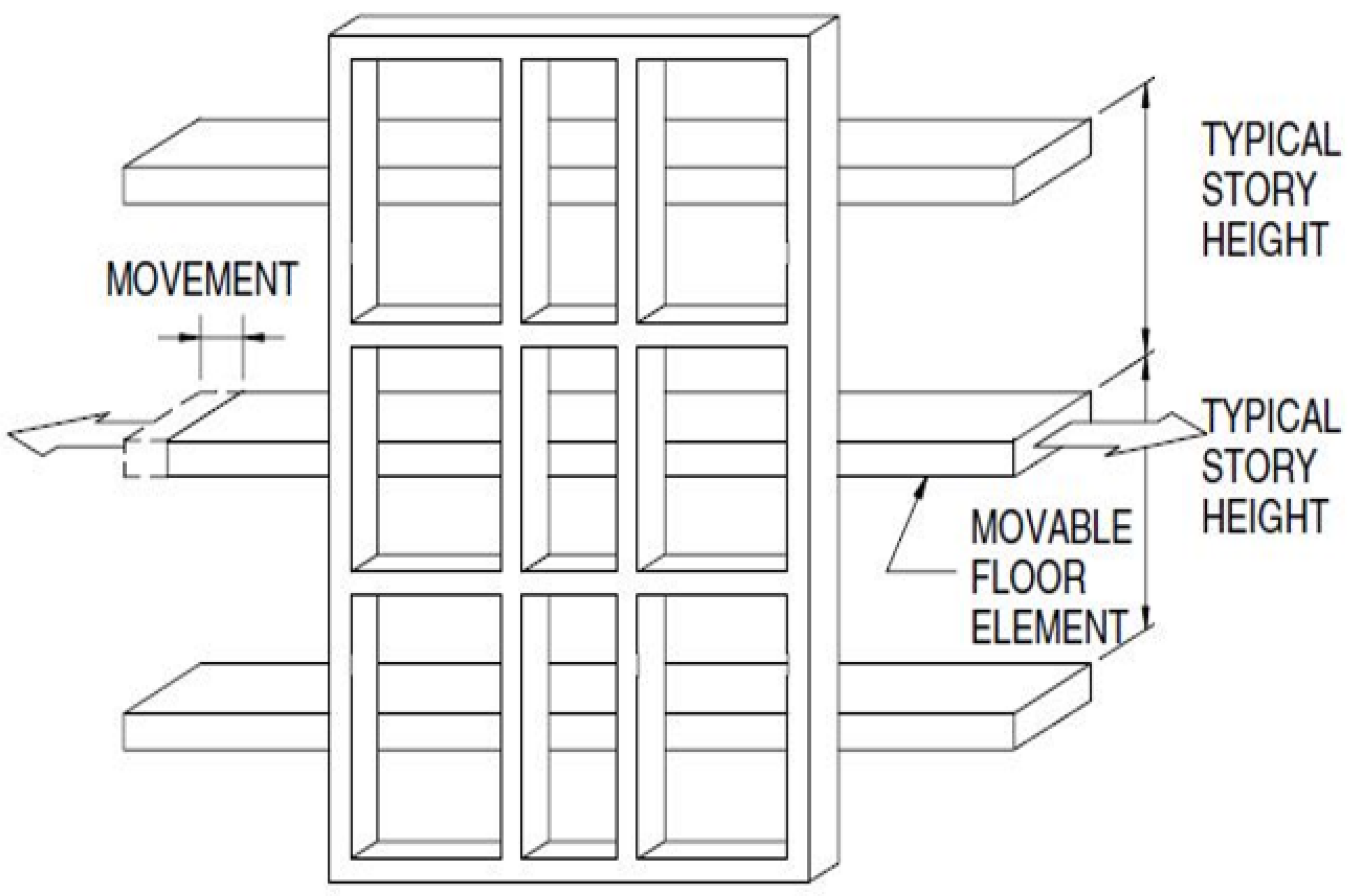
Figure 1.
Test methods in the AAMA 501.4 standard.

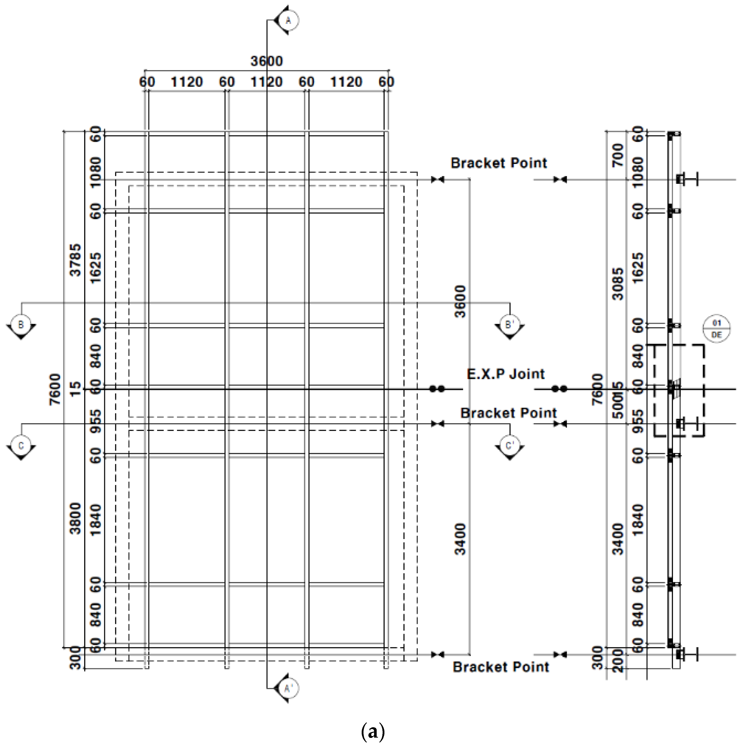
Figure 2.
Conventional stick curtain wall system: (a) front view; (b) cross-section.


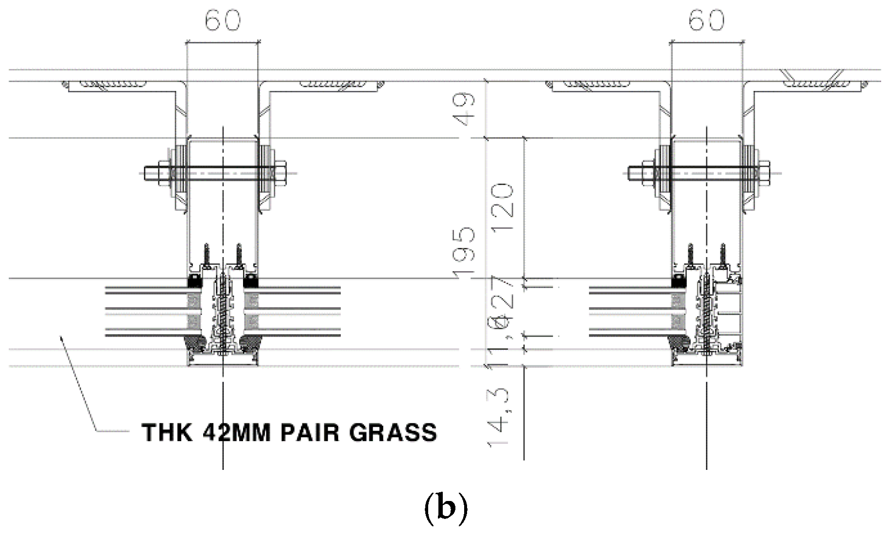
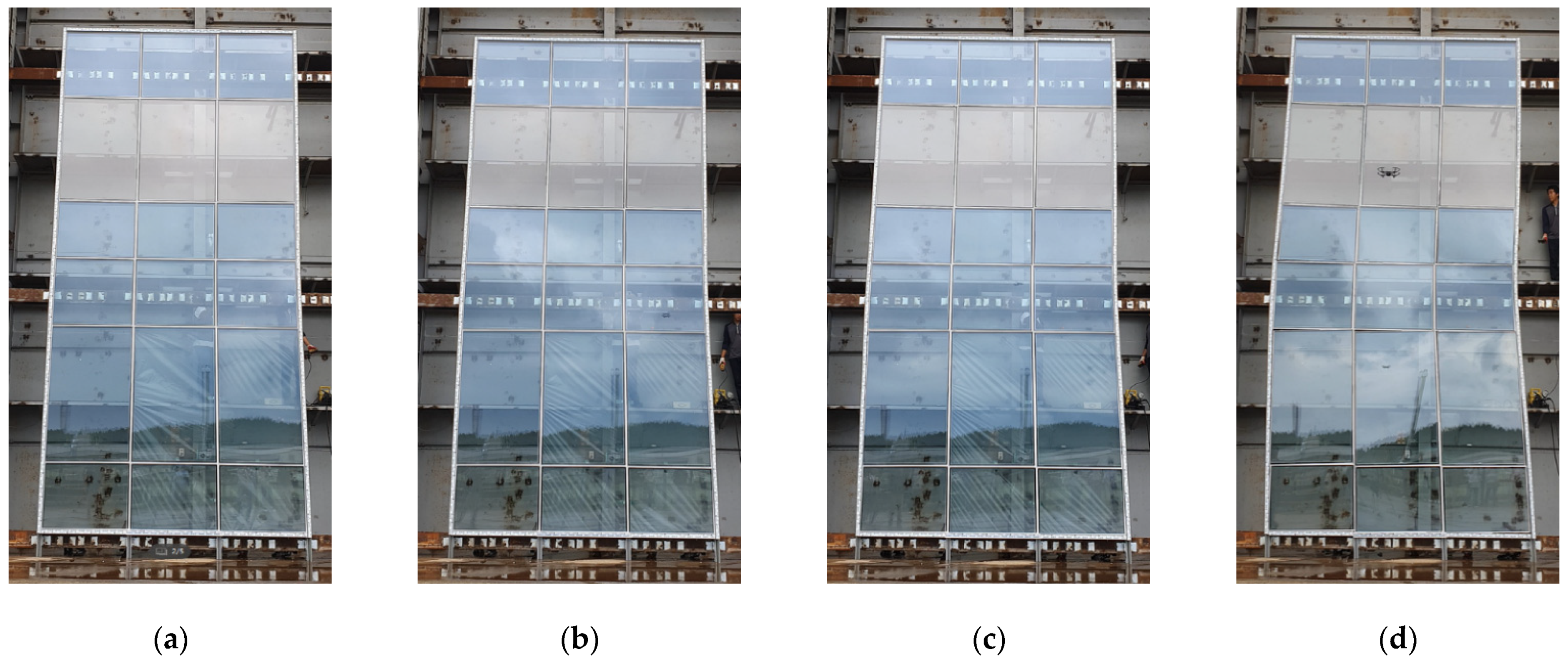
Figure 3.
Applied displacement based on seismic grade: (a) Special level 36 mm; (b) I level 54 mm; (c) II level 72 mm; (d) AAMA 501.6 level 150 mm.
Figure 3.
Applied displacement based on seismic grade: (a) Special level 36 mm; (b) I level 54 mm; (c) II level 72 mm; (d) AAMA 501.6 level 150 mm.

Figure 4.
Main vulnerabilities of non-seismic curtain wall: (a) external weather sealant breakage; (b) glass fallout; (c) curtain wall frame breakage; (d) expansion joint breakage.
Figure 4.
Main vulnerabilities of non-seismic curtain wall: (a) external weather sealant breakage; (b) glass fallout; (c) curtain wall frame breakage; (d) expansion joint breakage.

Figure 5.
Seismic fastener prototype (X-axis).

Figure 6.
Developed fastener prototype design.

Figure 7.
Displacement absorbing principle of seismic fastener: (a) X-axis movement; (b) Z-axis movement.
Figure 7.
Displacement absorbing principle of seismic fastener: (a) X-axis movement; (b) Z-axis movement.

Figure 8.
Displacement absorbing principle of the inter-story separated module.

Figure 9.
Dynamic seismic test method based on AAMA 501.6.

Figure 10.
Non-seismic curtain wall specimen: (a) front view; (b) side view.

Figure 11.
Seismic curtain wall specimen: (a) front view; (b) side view.

Figure 12.
Dynamic seismic waveform applied to the AAMA 501.6 test method.

Figure 13.
States of non-seismic curtain wall after the dynamic racking crescendo test: (a) silicone cracks (42 mm); (b) glass cracks (60 mm); (c) glass fallout (90 mm).
Figure 13.
States of non-seismic curtain wall after the dynamic racking crescendo test: (a) silicone cracks (42 mm); (b) glass cracks (60 mm); (c) glass fallout (90 mm).

Figure 14.
States of seismic curtain wall after the dynamic racking crescendo test: (a) no abnormalities detected in the front of the specimen; (b) no cracks or breakage of silicone; (c) no abnormalities detected in the upper fastener.
Figure 14.
States of seismic curtain wall after the dynamic racking crescendo test: (a) no abnormalities detected in the front of the specimen; (b) no cracks or breakage of silicone; (c) no abnormalities detected in the upper fastener.

Figure 15.
Details of full-frame FE model in solid form: (a) external shape of the FE model; (b) internal member detail; (c) chamber and aluminum frame; (d) anchor connection.
Figure 15.
Details of full-frame FE model in solid form: (a) external shape of the FE model; (b) internal member detail; (c) chamber and aluminum frame; (d) anchor connection.

Figure 16.
Details of the single-frame FE model in solid form: (a) FE model of conventional curtain wall; (b) FE model of seismic curtain wall; (c) internal member detail; (d) mobile fastener.
Figure 16.
Details of the single-frame FE model in solid form: (a) FE model of conventional curtain wall; (b) FE model of seismic curtain wall; (c) internal member detail; (d) mobile fastener.

Figure 17.
Designed model for each linear guide length.

Figure 18.
Response of the conventional curtain wall under static lateral drift.

Figure 19.
Major vulnerabilities of conventional curtain wall simulation: (a) mullion-to-fastener connection twist; (b) stress concentration on the edge of the glass; (c) aluminum frame fallout from the glass; (d) gasket twist; (e) expansion joint detachment; (f) stress concentration at expansion joint connection.

Figure 20.
Stress distribution in each member of non-seismic curtain wall during X-axis drift: (a) glass; (b) mullion-to-transom; (c) PVC; (d) aluminum-to-glass.
Figure 20.
Stress distribution in each member of non-seismic curtain wall during X-axis drift: (a) glass; (b) mullion-to-transom; (c) PVC; (d) aluminum-to-glass.

Figure 21.
Stress distribution in each member of non-seismic curtain wall during Y-axis drift: (a) aluminum; (b) glass-to-gasket; (c) aluminum-to-glass; (d) glass.
Figure 21.
Stress distribution in each member of non-seismic curtain wall during Y-axis drift: (a) aluminum; (b) glass-to-gasket; (c) aluminum-to-glass; (d) glass.

Figure 22.
Stress distribution in each member of non-seismic curtain wall during Z-axis drift: (a) glass; (b) aluminum; (c) PVC; (d) aluminum-to-fastener.
Figure 22.
Stress distribution in each member of non-seismic curtain wall during Z-axis drift: (a) glass; (b) aluminum; (c) PVC; (d) aluminum-to-fastener.

Figure 23.
Stress distribution in each member of seismic curtain wall during X-axis drift: (a) aluminum; (b) upper kicker; (c) PVC; (d) linear guide-to-fastener connection part.
Figure 23.
Stress distribution in each member of seismic curtain wall during X-axis drift: (a) aluminum; (b) upper kicker; (c) PVC; (d) linear guide-to-fastener connection part.

Figure 24.
Stress distribution in each member of seismic curtain wall during Y-axis drift: (a) upper fastener-to-rigid beam connection part; (b) rail-to-moving clip connection part; (c) glass; (d) aluminum-to-PVC connection part.
Figure 24.
Stress distribution in each member of seismic curtain wall during Y-axis drift: (a) upper fastener-to-rigid beam connection part; (b) rail-to-moving clip connection part; (c) glass; (d) aluminum-to-PVC connection part.

Figure 25.
Stress distribution in each member of seismic curtain wall during Z-axis drift: (a) upper fastener-to-rigid beam connection part; (b) lower fastener-to-rigid beam connection part; (c) fastener-to-bolt connection part; (d) external aluminum frame.
Figure 25.
Stress distribution in each member of seismic curtain wall during Z-axis drift: (a) upper fastener-to-rigid beam connection part; (b) lower fastener-to-rigid beam connection part; (c) fastener-to-bolt connection part; (d) external aluminum frame.

Figure 26.
Comparison of appearance changes under applied X-axis inter-story drift: (a) non-seismic curtain wall module; (b) seismic curtain wall module.
Figure 26.
Comparison of appearance changes under applied X-axis inter-story drift: (a) non-seismic curtain wall module; (b) seismic curtain wall module.

Figure 27.
Comparison of appearance changes under applied Y-axis inter-story drift: (a) non-seismic curtain wall module; (b) seismic curtain wall module.
Figure 27.
Comparison of appearance changes under applied Y-axis inter-story drift: (a) non-seismic curtain wall module; (b) seismic curtain wall module.

Figure 28.
Comparison of appearance changes under applied Z-axis inter-story drift: (a) non-seismic curtain wall module; (b) seismic curtain wall module.
Figure 28.
Comparison of appearance changes under applied Z-axis inter-story drift: (a) non-seismic curtain wall module; (b) seismic curtain wall module.

Figure 29.
Seismic curtain wall deformation: linear guide length 150 mm.

Figure 30.
Stress distribution applied to each member: linear guide length 150 mm.

Figure 31.
Seismic curtain wall deformation: linear guide length 100 mm.

Figure 32.
Stress distribution applied to each member: linear guide length 100 mm.

Figure 33.
Seismic curtain wall deformation: linear guide length 50 mm.

Figure 34.
Stress distribution applied to each member: linear guide length 50 mm.

Figure 35.
Relationship of linear guide length to maximum stress applied to the curtain wall.

Figure 36.
Deformation of weak areas when linear guide length of 50 mm is applied.

Figure 37.
Non-seismic curtain wall deformation.

Figure 38.
Specimens for evaluating insulation and airtightness performance: (a) insulation performance evaluation specimen; (b) airtightness performance evaluation specimen.
Figure 38.
Specimens for evaluating insulation and airtightness performance: (a) insulation performance evaluation specimen; (b) airtightness performance evaluation specimen.

Figure 39.
Specimens for evaluating watertightness and wind pressure performance: (a) watertightness performance evaluation specimen; (b) wind pressure performance evaluation specimen.
Figure 39.
Specimens for evaluating watertightness and wind pressure performance: (a) watertightness performance evaluation specimen; (b) wind pressure performance evaluation specimen.


Table 1.
Methods to reinforce the seismic performance of curtain walls.
| Classification | Principal |
|---|---|
| Edge Clearance | A method to secure deformation prevention by setting a clearance between the edge of the glass and the frame when fracture stress occurs as the glass undergoes in-plane deformation |
| SSG (Structural Silicone Glazing) | A method of supporting glass by adhering the glass panel to a frame member using a structural silicone sealant |
| Rocking | A method of preventing impact and fallout of the exterior panels by absorbing the in-plane deformation via rotation of the exterior panel against the inter-story drift of the building during earthquakes |
| Swaying | A method to prevent impact and fallout of exterior panels by absorbing deformation via suspending exterior panels against the inter-story drift of buildings during earthquakes and moving them horizontally, with the upper part free to move |
Table 2.
Designed member specifications of specimen components.
| Profile | Aluminum Curtain Wall/SC-ECW-ST-01 | |
|---|---|---|
| Dimension | 3600 mm (W) × 7600 mm (H) | |
| Aluminum frame | Mullion | (60 mm × 150 mm) Extruded bar |
| Transom | (60 mm × 150 mm) Extruded bar | |
| Thermal break | Polyamide (Mullion and transom) | |
| Glass | 42 mm Low-E triple glass (6 mm Semi-reinforced glass + 12 mm Air + 6 mm Plain glass + 12 mm Air + 6 mm Semi-reinforced glass) | |
| AL. sleeve of expansion joint | 250 mm | |
| Anchor part | Steel anchor | 2L-110 × 100 × 9T × 120LG |
| Spacing | Refer to Figure 2 | |
| Finish | AL. Bar | PVDF Coat |
| Steel anchor | Hot-dip galvanizing | |
Table 3.
Summary of seismic performance evaluation results.
| Lateral Displacement | Cycle | Vulnerabilities | Remarks |
|---|---|---|---|
| Seismic classification (Special) (0.010 × ) = ±36.00 mm | 3 | None | Distance between anchor points of curtain wall mullions = 3600 mm ( = xth story height) |
| Seismic classification (I) (0.015 × ) = ±54.00 mm | 3 | Partial breakage of weather sealant installed outside frame | |
| Seismic classification (II) (0.020 × ) = ±72.00 mm | 3 | Expansion of breakage area of weather sealant installed outside the curtain wall | |
| Purpose of displacement in this study ±150 mm | 3 | Glass breakage and fallout | |
| Residual deformation after weather sealant breakage |
Table 4.
Designed member specifications of non-seismic specimen components.
| Dimension | Façade Frame | 4000 mm (W) × 4200 mm (H) | |||||
| Story Height | 4000 mm | ||||||
| Frame | Mullion | 60 mm × 195 mm (Aluminum extruded bar) | |||||
| Transom | 60 mm × 195 mm (Aluminum extruded bar) | ||||||
| Thermal break | PVC (Mullion and Transom) | ||||||
| Glass Spec. | Glass Thickness and General Spec. | 42 mm Triple glass (6Low-e + 12Air + 6Clear + 12Air + *6Low-e) | |||||
| Reinforced Glass Spec. | 6Low-e: SKN154II (Semi-reinforced glass) | ||||||
| Laminated Glass Spec. | None | ||||||
| Glass Dimension | a | 959 mm () × 1453 mm () | |||||
| b | 959 mm () × 738 mm () | ||||||
| Gasket | None | ||||||
| Sealant | External: Weather sealant/Internal: Structural sealant | ||||||
| Glass Bite Depth and Clearance | Glass Bite Depth | Left(L)/Right(R) | 17.0 mm | Cap type | |||
| Up(U)/Down(L) | 14.0 mm | Cap type | |||||
| Classification | Glass size (mm) | Frame inner diameter (mm) | Clearance | ||||
| Glass-Frame Clearance | Fix | (L/R) | 959 | 968 | 4.5 mm | ||
| (U/D) | 1453 | 1467 | 7.0 mm | ||||
| Casement | (L/R) | 959 | 968 | 4.5 mm | |||
| (U/D) | 738 | 752 | 7.0 mm | ||||
| AL. Sleeve of Expansion Joint | None | ||||||
| Finish | AL. Bar | Powder coat | |||||
| Steel Anchor | Hot-dip galvanizing | ||||||
Table 5.
Designed member specifications of seismic specimen components.
| Dimension | Façade Frame | 4005 mm (W) × 4200 mm (H) | |||||
| Story Height | 4000 mm | ||||||
| Frame | Mullion | 60 mm × 175 mm (Aluminum extruded bar) | |||||
| Transom | 60 mm × 175 mm (Aluminum extruded bar) | ||||||
| Thermal Break | PVC (Mullion and Transom) | ||||||
| Glass Spec. | Glass Thickness and General Spec. | 42 mm Triple glass (6Low-e + 12Air + 6Clear + 12Air + *6Low-e) | |||||
| Reinforced Glass Spec. | 6Low-e: SKN154II (Semi-reinforced glass) | ||||||
| Laminated Glass Spec. | None | ||||||
| Glass Dimension | a | 1279 mm () × 1449 mm () | |||||
| b | 1279 mm () × 734 mm () | ||||||
| Gasket | None | ||||||
| Sealant | External: Weather sealant/Internal: Structural sealant | ||||||
| Glass Bite Depth and Clearance | Glass Bite Depth | Left(L)/Right(R) | 120 mm | Cap type | |||
| Up(U)/Down(L) | 120 mm | Cap type | |||||
| Classification | Glass size (mm) | Frame inner diameter (mm) | Clearance | ||||
| Glass-Frame Clearance | Fix | (L/R) | 1279 | 1298 | 9.5 mm | ||
| (U/D) | 1449 | 1468 | 9.5 mm | ||||
| Casement | (L/R) | 1279 | 1298 | 9.5 mm | |||
| (U/D) | 734 | 753 | 9.5 mm | ||||
| AL. Sleeve of Expansion Joint | None | ||||||
| Finish | AL. Bar | Powder coat | |||||
| Steel Anchor | Hot-dip galvanizing | ||||||
Table 6.
Dynamic racking crescendo test results.
| Classification | Test Item | Test Result | |
|---|---|---|---|
| Displacement Measurement | Percentage of Test Specimen Height | ||
| Non-seismic specimen | ΔSeal cracking | >42 mm | >1.11% |
| ΔCracking | >60 mm | >1.58% | |
| ΔFallout | >90 mm | >2.37% | |
| Note | -A large number of cracks and breakage occurred. -Finally, glass fallout occurred. | ||
| Seismic specimen | Δ Seal cracking | >150 mm | >3.75% |
| ΔCracking | >150 mm | >3.75% | |
| ΔFallout | >150 mm | >3.75% | |
| Note | -No cracks and breakage up to 150 mm displacement. | ||
ΔSeal cracking: The relative seismic displacement (drift) at which initial seal cracking is visually noted. ΔCracking: The relative seismic displacement (drift) at which initial glass cracking is visually noted. ΔFallout: The relative seismic displacement (drift) at which glass fallout from the curtain wall, storefront, or partition occurs.
Table 7.
Material properties used in the FE model.
| Material | Density [kg/m3] | Modulus of Elasticity [GPa] | Poison’s Ratio |
|---|---|---|---|
| Aluminium | 2700 | 72 | 0.34 |
| PVC | 1400 | 0.1655 | 0.4 |
| Steel | 7800 | 210 | 0.3 |
| Concrete | 2300 | 26 | 0.167 |
| Glass | 2700 | 70 | 0.25 |
Table 8.
Vulnerability analysis of conventional curtain wall components.
| Components | Vulnerability Type |
|---|---|
| Aluminum |
|
| Fastener |
|
| Glass |
|
| Gasket |
|
| Expansion joint |
|
Table 9.
Comparison of stress at maximum drift according to the axial direction.
| Direction of Drift. | FE Model | Stress at Maximum Drift (MPa) | Stress Concentration Part |
|---|---|---|---|
| X-Axis | Non-seismic curtain wall | 405 | Diagonal edge and fastener connection joint in aluminum |
| Seismic curtain wall | 3.38 | The bolted joint of the fastener closest to the point of drift | |
| Y-Axis | Non-seismic curtain wall | 460.5 | Edge of mullion |
| Seismic curtain wall | 455.5 | Fastener closest to the point of drift | |
| Z-Axis | Non-seismic curtain wall | 2486 | Center part of mullion |
| Seismic curtain wall | 1.2 | Fastener closest to the point of drift |
Table 10.
Peak stress applied to each member.
| Linear Guide Length (mm) | Peak Stress (MPa) | ||||
|---|---|---|---|---|---|
| Aluminum | PVC | Fastener | Linear Guide | Glass | |
| 50 | 409.9 | 10 | 116.1 | 53.4 | 4 |
| 100 | 192.3 | 3.8 | 61.2 | 18.7 | 1.4 |
| 150 | 12.8 | 0.35 | 14.4 | 7.29 | 0.45 |
Table 11.
Comparison of analysis results of non-seismic curtain wall and seismic curtain wall.
| Curtain Wall Type | Peak Stress (MPa) | Peak Stress Point |
|---|---|---|
| Non-seismic curtain wall | 1270 | Fastener bonded to diagonal edge aluminum |
| Seismic curtain wall (Linear guide Length: 50 mm) | 409.9 | Upper fastener-to-mullion connection part |
| Seismic curtain wall (Linear guide Length: 100 mm) | 192.3 | |
| Seismic curtain wall (Linear guide Length: 150 mm) | 12.8 |
Table 12.
Specimen specifications for evaluation of heat insulation and airtightness performance (and/or watertightness and wind pressure).
Table 12.
Specimen specifications for evaluation of heat insulation and airtightness performance (and/or watertightness and wind pressure).
| Frame Material | Aluminum | ||
| Opening and Closing Method | Fixed window | ||
| Frame Width (mm) | 175 | ||
| Single Window/Double Window | Single window | ||
| Glass Composition | Division | Thickness (mm) | Glass type |
| - | 42 | Triple glass | |
| Roy 6 mm (soft coating, SKN154II, H/S) + Argon gas 12 mm + Typical 6 mm + Argon gas 12 mm + Typical 6 mm | |||
| Spacer Material | Division | Material | |
| - | Synthetic resin | ||
Table 13.
Heat transmittance test results.
| Division | 1st time | 2nd time | 3rd time | |
| Air Temperature [°C] | Constant Temperature Room | 20.03 | 20.02 | 20.02 |
| Protective Heat Box | 19.86 | 19.85 | 19.85 | |
| Low-Temperature Room | −0.50 | −0.50 | −0.51 | |
| Temperature Difference ※1 | 20.36 | 20.35 | 20.35 | |
| Calorie [W] | Total Supply Calories ※2 | 103.44 | 103.38 | 104.05 |
| Calibration Calories ※3 | 38.16 | 38.16 | 38.18 | |
| Passing Calories Through Specimen | 65.28 | 65.22 | 65.87 | |
| Heat Transfer Resistance on Both Surfaces of the Specimen [(m2·K)/W] | Inner Surface Heat Transfer Resistance | 0.12 | 0.12 | 0.12 |
| External Surface Heat Transfer Resistance | 0.06 | 0.06 | 0.06 | |
| Correction Value | −0.02 | −0.02 | −0.02 | |
| Heat Transmission Rate [W/(m2·K)] | 0.813 | 0.813 | 0.821 | |
| Average: 0.816 | ||||
| Heat Transfer Resistance [(m2·K)/W] | 1.230 | 1.231 | 1.218 | |
| Average: 1.226 | ||||
| Remark |
| |||
※1 Temperature difference: The difference between the average air temperature at 9 points in the heating box (10 cm from the sample surface) and the average air temperature at 9 points in the low-temperature room (10 cm from the sample surface) ※2 Total amount of heat supplied: Total amount of heat supplied by the fan and heater in the heating box ※3 Calibration calories: calories calibrated on the circumferential wall of the heating box and the test object attachment frame.
Table 14.
Air infiltration test results.
| Dimension | Specimen Size | Window Frame Inner Dimensions and Area | |||
|---|---|---|---|---|---|
| Height (mm) | Width (mm) | Height (mm) | Width (mm) | Area (m2) | |
| 2000 | 2000 | 1880 | 1880 | 3.534 4 | |
| Test result | Pressure difference (Pa) | Ventilation (m3/(h·m2)) | |||
| 10 | 0.00 | ||||
| 30 | 0.00 | ||||
| 50 | 0.00 | ||||
| 100 | 0.13 | ||||
| Airtightness grade | 1 grade | ||||
| Airtightness grade line |  | ||||
| ※ Because the ventilation volume at 10, 30, and 50 Pa pressure is 0.00 m3/(h∙m2), it is not displayed on the airtightness rating line. | |||||
| Laboratory environment | Temperature: (26.1 ± 1.0) °C; Humidity: (61.7 ± 5.0)% R.H.; Air pressure: (1013.2 ± 0.1) hPa | ||||
Table 15.
Water penetration test results.
| Dimensions and Water Spray Volume | Specimen Size | Water Spray Volume | |||
|---|---|---|---|---|---|
| Height (mm) | Width (mm) | 4 L/(m2·min) | |||
| 2000 | 2000 | ||||
| Test grade | 35 Grade (Test pressure: 350 Pa (175 Pa ∼ 525 Pa)) | ||||
| Test result | Leak phenomenon | Symbol | |||
| Upper window frame | - |  : Penetration of water : Penetration of water | |||
| Lower window frame | - |  : Bubble : Bubble | |||
| Sun frame (left) | - |  : Outflow : Outflow | |||
| Sun frame (Right) | - |  : Outflow from the frame and significant outflow into the interior : Outflow from the frame and significant outflow into the interior | |||
| Upper corner | - |  : Injection : Injection | |||
| Lower corner | - |  : Injection out of the frame : Injection out of the frame | |||
| Etc. | - |  : Spray : Spray | |||
 : Spray out of the frame : Spray out of the frame | |||||
 : Overflow out of the frame : Overflow out of the frame | |||||
| 35 grade suitable | |||||
| Leak location |  | ||||
| ※ No leakage phenomenon. | |||||
| Laboratory environment | Temperature: (25.3 ± 1.0) °C; Humidity: (57.3 ± 5.0)% R.H. | ||||
Table 16.
Wind resistance test results.
| Specimen Size | Height (mm) | Width (mm) | ||||||
|---|---|---|---|---|---|---|---|---|
| 2000 | 2000 | |||||||
| Test Grade | 280 Grade (Maximum test pressure: ±2800 Pa) | |||||||
| Test Result | Pressure (Pa) | Displacement by measurement location (mm) | Displacement (A) ※1 | Displacement rate (A/H) ※2 | Deformation (δ) ※3 | Strain (δ/L) ※4 | ||
| ① | ② | ③ | ||||||
| 700 | −0.84 | −6.54 | −0.82 | −6.54 | −0.0035 | −5.71 | −0.0031 | |
| 1400 | −2.09 | −11.09 | −1.63 | −11.09 | −0.0059 | −9.23 | −0.0050 | |
| 2100 | −3.06 | −14.64 | −2.40 | −14.64 | −0.0078 | −11.91 | −0.0065 | |
| 2800 | −4.03 | −17.63 | −3.09 | −17.63 | −0.0094 | −14.07 | −0.0076 | |
| −700 | 0.36 | 6.55 | 0.64 | 6.55 | 0.0035 | 6.05 | 0.0033 | |
| −1 400 | 1.11 | 11.41 | 1.30 | 11.41 | 0.0061 | 10.21 | 0.0055 | |
| −2 100 | 2.29 | 15.39 | 1.91 | 15.39 | 0.0082 | 13.29 | 0.0072 | |
| −2 800 | 3.41 | 18.54 | 2.42 | 18.54 | 0.0099 | 15.63 | 0.0085 | |
| ※1 Displacement (A): Displacement at measurement position② ※2 Displacement rate (A/H): H = 1880 mm ※3 Deformation (δ): δ = ② − (①+③)/2 ※4 Strain (δ/L): L = 1840 mm | ||||||||
| Deformation test | OK | |||||||
| Cyclic test | OK | |||||||
| Safety test | OK | |||||||
| Grade 280 suitable | ||||||||
| Displacement measurement location |  | |||||||
| Laboratory environment | Temperature: (25.3 ± 1.0) °C; Humidity: (57.3 ± 5.0)% R.H. | |||||||
Publisher’s Note: MDPI stays neutral with regard to jurisdictional claims in published maps and institutional affiliations. |
© 2021 by the authors. Licensee MDPI, Basel, Switzerland. This article is an open access article distributed under the terms and conditions of the Creative Commons Attribution (CC BY) license (https://creativecommons.org/licenses/by/4.0/).
Share and Cite
MDPI and ACS Style
Lee, H.; Oh, M.; Seo, J.; Kim, W. Seismic and Energy Performance Evaluation of Large-Scale Curtain Walls Subjected to Displacement Control Fasteners. Appl. Sci. 2021, 11, 6725. https://0-doi-org.brum.beds.ac.uk/10.3390/app11156725
AMA Style
Lee H, Oh M, Seo J, Kim W. Seismic and Energy Performance Evaluation of Large-Scale Curtain Walls Subjected to Displacement Control Fasteners. Applied Sciences. 2021; 11(15):6725. https://0-doi-org.brum.beds.ac.uk/10.3390/app11156725
Chicago/Turabian StyleLee, Heonseok, Myunghwan Oh, Junwon Seo, and Woosuk Kim. 2021. "Seismic and Energy Performance Evaluation of Large-Scale Curtain Walls Subjected to Displacement Control Fasteners" Applied Sciences 11, no. 15: 6725. https://0-doi-org.brum.beds.ac.uk/10.3390/app11156725
Note that from the first issue of 2016, this journal uses article numbers instead of page numbers. See further details here.