
A Form-Finding Method for Branching Structures Based on Dynamic Relaxation


1
College of Construction Engineering, Jilin University, Changchun 130012, China
2
School of Management, Guangzhou University, Guangzhou 510006, China
*
Author to whom correspondence should be addressed.
Appl. Sci. 2021, 11(15), 7165; https://0-doi-org.brum.beds.ac.uk/10.3390/app11157165
Submission received: 24 June 2021
/
Revised: 28 July 2021
/
Accepted: 30 July 2021
/
Published: 3 August 2021
(This article belongs to the Section Civil Engineering)
Abstract
:Branching structure is often used as a supporting structure of the grid shell due to its geometrical and force-transferring features, and the rationality of its shape is very important. The “physical” and “numerical” hanging models can be used for the joint form-finding of the branching structure and free-form grid shell. However, slack elements may exist in the equilibrium model which corresponds to the inefficient members in the form-found branching structure. To solve this problem, a form-finding method of branching structure based on dynamic relaxation is proposed in this study. The proposed method clusters the elements of the branching model and equalizes the axial forces of the elements in the same cluster, in other words, there are no slack elements in the equilibrium branching model. This method overcomes the defect that the equilibrium branching model may have slack elements and needs many manual adjustments during the procedure of determining the rational shape of a branching structure, and effectively prevents the inefficient members existing in the form-found structure. Numerical examples are provided to demonstrate the characteristics of the proposed method and its effectiveness is verified as well.
1. Introduction
A branching structure that looks like a tree and unfolds step by step from the bottom to the top can transfer the large-area roof load to a local support due to its unique shape [1,2]. Therefore, the branching structures are often used in railway stations, airports, and other large-span space structures. The bending moments in the branching structure need to be reduced as much as possible under the given load to find a reasonable shape of the branching structure. In the past, scholars have developed physical model experiments to determine the shapes of branching structures. Frei Otto first employed the hanging model experiment to determine the shapes of branching structures followed by other scholars’ efforts to develop various kinds of physical model experiments to determine the branching structure shapes [3].
In recent years, due to the advances of computer-aided simulation technology, increasing attention was attracted to using numerical methods instead of solely using physical model experiments to solve the branching structure shape problem. These methods can be classified into two categories. One category is the structural shape or topology optimization, which takes a certain index, such as strain energy [4,5] and stress uniformity [6], to measure the structural performance and as the optimization objective. The other category is based on the principle of physical model experiments. Chen et al. established a sliding criterion equation of cable, then used the sliding cable element to determine the rational shape of branching structures [7,8]. Wu et al. proposed a reverse hanging recursive method to determine the branching structural shapes, and systematically studied the stability of the members of the branching structures [9,10]. Eguchi et al. proposed a design method to generate “natural” shapes of branching structures with curved branches [11,12]. Zhao et al. proposed the double element method and applied it to the shape-finding analysis of branching structure [13]. In addition to the above-mentioned numerical methods for branching structure, other methods that can simulate the physical model experiment also can be used to determine the reasonable shape of branching structure, such as dynamic relaxation method [14,15], vector form intrinsic finite element method [16,17,18], and generalized inverse method [10,11,12,13,14,15,16,17,18,19,20,21]. The branching structure is often used as the supporting structure of the free-form latticed shell. To determine the reasonable shape of the whole structure, it is necessary to consider both the upper latticed shell and the lower branching structure. The physical and computational hanging upside-down models can be applied to the form-finding of both branching structure and free-form latticed shell. However, when the flexible model becomes equilibrium, there may be slack parts in the equilibrium branching model and these slack parts correspond to the inefficient members of the form-found branching structure. The slack parts in the model are difficult to avoid and therefore designers need to manually adjust the model many times to prevent the generation of the inefficient members in form-found branching structure. The adjustment is time-consuming and error-prone when establishing the model.
Dynamic relaxation method is a frequently used form-finding method. In this study, the element cluster is introduced into the dynamic relaxation method to solve the problem causing by the slack elements of the equilibrium branching model when a computational hanging model is used to determine the shapes of branching structures. The remainder of this study is as follows. The illustration of the numerical implementation of the method is presented in Section 2. Then, a simple example is given to illustrate the characteristics and implementation in Section 3. In Section 4, a numerical example of a free-form latticed shell supported by branching structures is given to verify the effectiveness of the method. Finally, the conclusions are presented in Section 5.
2. Method
The branching structure transfers the large area load acting on the upper structure to the designated position through branches in each level. When using a branching model to determine the shape of the branching structure, we can avoid the slack elements of the equilibrium branching model by equalizing the axial force of the elements in the same branching level.
2.1. Governing Equation
The Governing equation of particle movement of dynamic relaxation method is
where M is the mass matrix, is the particle velocity vector at time t, C is the damping vector, is the residual force vector, is the internal force vector and the external force vector.
Assuming that the velocity varies linearly in time step Δt, so the acceleration of the particle in Δt is constant. The velocity and acceleration of particle i at the time t can be expressed as
where is the velocity of particle i in direction j (j represents x, y or z) at time t. According to Equations (1)–(3), the velocity of particle i at the time t + Δt/2 can be obtained as
where j represents the direction of x, y or z, is the damping coefficient of particle i in the direction j, is the residual force of particle i in j direction. Thus, the updated geometry at time t + Δt is
where is the nodal position vector at time t. The kinetic energy at t + Δt is
where KEt+Δt is the kinetic energy at t + Δt.
The convergence of the computation is affected by the mass matrix M, damping coefficient, and time increment Δt. In the following numerical examples, the mass setting is based on the method given in the literature [15], and the time increment Δt is determined by trial calculation. Kinetic damping proved to be stable and rapidly convergent [15]. We adopt kinetic damping in which viscous damping coefficients in Equation (4) are no longer needed but instead all the nodal velocities are set to zero when a kinetic energy peak is detected.
2.2. Element Cluster
The elements in the branching model are clustered through defining a clustering matrix B, and make the internal forces of the elements in the same cluster equal. The elements in the clustering matrix are defined as follows:
The element lengths are assembled into the vector l
where li is the length of the ith element in the model. To make the internal forces of the elements in the same cluster equal, the change of the total length of the elements in each cluster needs to be considered to calculate the internal forces. By left multiplying l by B, the vector composed of the lengths of the element clusters can be obtained.
where β is the number of element clusters and Li represents the total length of the elements in the ith cluster. The internal force of the jth element cluster at time t is
where is the total length of the elements in the jth cluster at time t, E is the elastic modulus of the element, A is the cross-sectional area of the element, and is the initial internal force of the elements in jth cluster. Thus, the element internal forces can be obtained.
where n is the number of elements, ti and Tj are the internal forces of the ith element and the jth element cluster respectively. So far, the residual force on any particle can be obtained by the following formula
where q is the number of elements meeting at particle i, is the residual force of particle i in the j direction (direction x, y or z) at time t, is the external force component acting on particle i in the j direction, and is the nodal force component caused by internal force of the kth element connected with particle i in the j direction. By introducing matrix B, the elements are clustered and the equal internal forces of the elements in the same cluster are realized. The setting of clustering matrix B is determined by the designers’ intent.
The geometric of the model is updated through iterative calculation until the convergence condition is satisfied. In this study, the convergence condition is reached when the following inequality is satisfied
where is the residual force on the ith particle, n is the number of particles, ε is the threshold.
3. Characteristics of the Element-Clustered Method
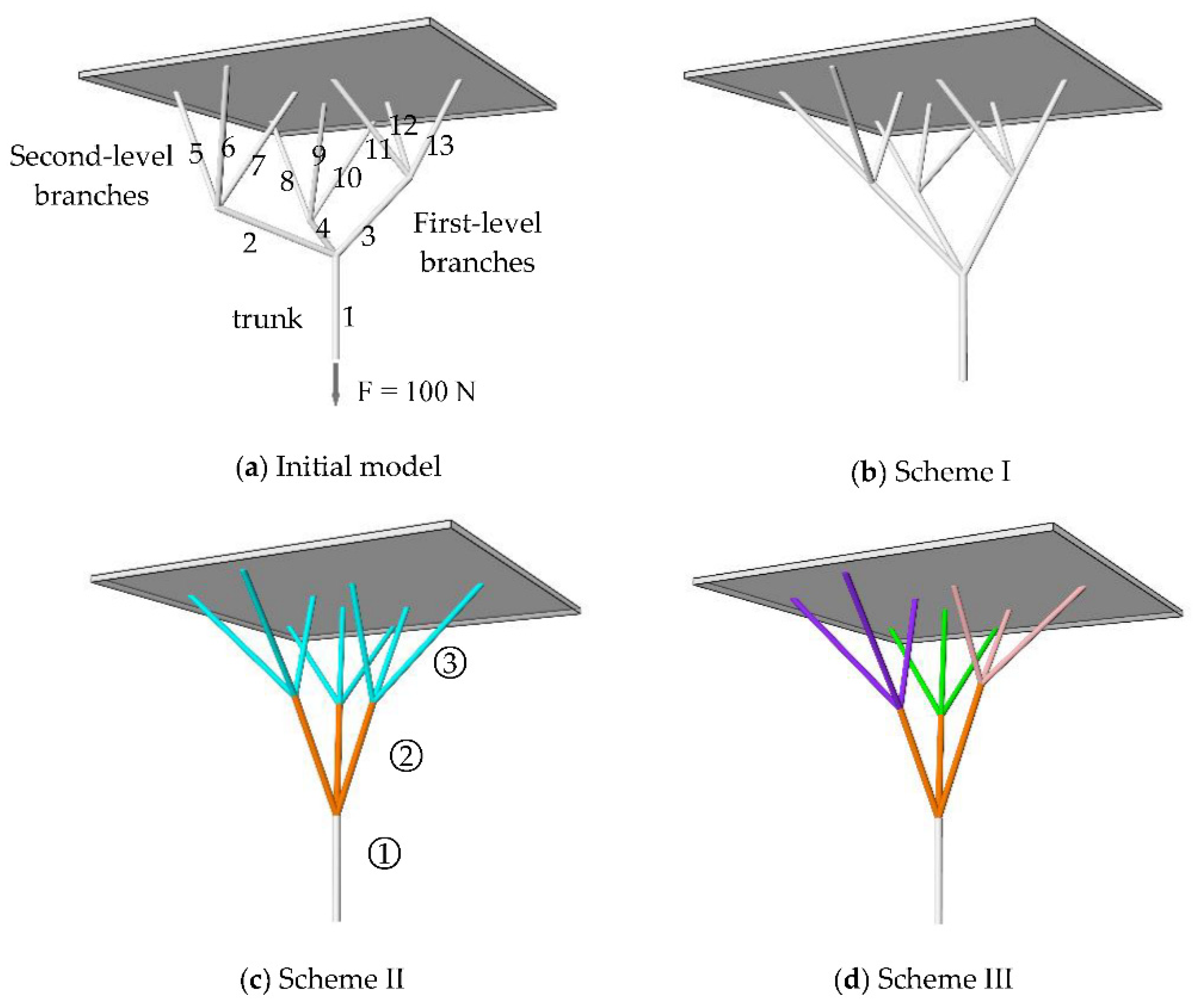
In this section, a simple example is given to illustrate the influence of the setting of element clusters on the form found results and the implementation process of the method. Figure 1a shows a branching model, which is composed of the trunk and two-level branches. The elements in the model are numbered. The upper nodes of the model are connected to a board and these nodes are fixed. A vertical downward load is applied to the bottom node to simulate a common physical experiment for determining the shape of branching structures. In the model, different element clusters are used to obtain different shape schemes, and the results are compared with those obtained by the traditional dynamic relaxation method.
The form found shape shown in Figure 1b is obtained by the traditional dynamic relaxation method. In this process, the compressive elastic modulus of the element is not considered but only the tensile elastic modulus is considered, because we assume that the model is composed of cables that can only bear tensile axial forces. When the model reaches an equilibrium state, the internal forces of the elements are shown in Table 1. It is easy to observe that there are elements whose internal forces are much smaller than the others in the second-level branches.
Figure 1c shows the equilibrium shape of the model when elements in the same branching level are clustered. In this example, the elements are assigned to three clusters. As shown in Figure 1c, different color represents a different cluster and the elements with the same color are in the same cluster. The axial forces of the elements in the same cluster are almost equal in scheme II according to Table 1 data, and there are no slack elements in the model. To further illustrate the formation of element clusters, the clustering matrix B corresponding to Figure 1c is given. Element 1 is in cluster ①, elements 2–4 are in cluster ②, and elements 5–13 are in cluster ③. According to Equation (7), the clustering matrix B is
In the form-found result shown in Figure 1d, all elements are assigned to five element clusters. There are three element clusters in the second-level branches, each cluster contains three interconnected elements. The three elements in the first-level branch form the fourth cluster. The trunk acts as a cluster alone. As shown in Figure 1d, same as the previous figure, the elements are organized by color and each color type represents a cluster. From Table 1, the axial forces of elements in the same cluster are almost equal, and there are no slack elements in the model in scheme III.
In scheme I, there are slack elements in the equilibrium model. When the structure is determined according to this shape, there will be inefficient members in the structure. In schemes II and III, the automatic adjustment of the model eliminates all slack elements by introducing element clusters. In scheme II, the elements 5–13 (second-level branches) are in the same cluster, it determines that the axial forces of these elements must be equal in the equilibrium model. Different from scheme II, in scheme III the elements 5–13 are assigned to three clusters, which results in the force-bearing states of these elements are different from that of scheme II, so the two form-found shapes are different. The resultant shape is determined by forces and vice versa. The model cannot reach an equilibrium state if the element in each cluster can’t reach the same force-bearing status. This will likely happen when we cluster elements from different branching levels. Therefore, the best practice for element clustering is to always collect elements from the same branching level into a cluster.
4. Numerical Example
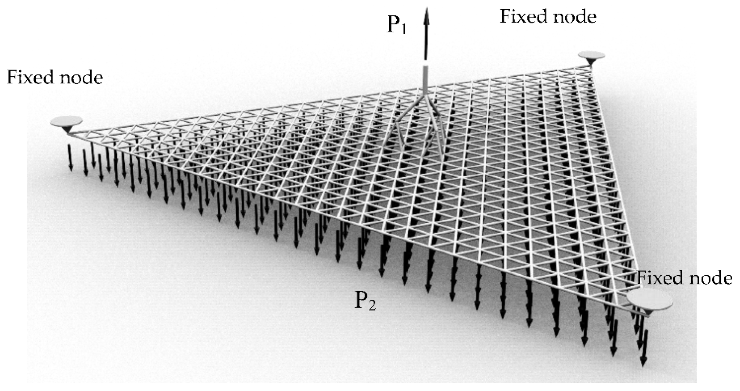
In the form-finding of a latticed shell with branching supporting structure, the net-shaped model and branching model change together, and when the whole model reaches equilibrium, the slack element is easy to appear in the branching model in this condition.
Figure 2 shows a flexible model composed of a branching model and a net-shaped model. The nodes at the three corners of the net-shaped model are fixed, the other nodes are subjected to the vertical downward force (0.5 N), and the top node of the branching model is subject to the vertical upward force (20 N). In the numerical calculation, the axil stiffness EA of the element is set as 5000 (E is elastic modulus and A is cross-section area). The traditional dynamic relaxation method and the element-clustered method proposed in this paper are used in this initial model. Since we want to simulate a hanging model composed of cables that can only bear tensile axial forces, therefore in the two methods, only the tensile stiffness of the element is considered, and the compressive stiffness is not considered. Figure 3a shows the form-found results of the traditional dynamic relaxation method, and Figure 3b shows the form-found result of the proposed element-clustered method. In the element-clustered method, the elements in the same branching level in the branching model form an element cluster. The results obtained by the two methods are similar in overall shape. To compare the branching structures generated by the two methods clearly, the two structures are placed in the same position in Figure 4, the red one is generated by the element-clustered method and the blue one is generated by the dynamic relaxation method. It is observable that the two branching structure shapes are different. When using the element clustered method to determine the rational shape of a branching structure, the elements in the same branching level are clustered and it influences the internal forces of these elements in the equilibrium model, so we obtain a different shape from that generated by the dynamic relaxation method.
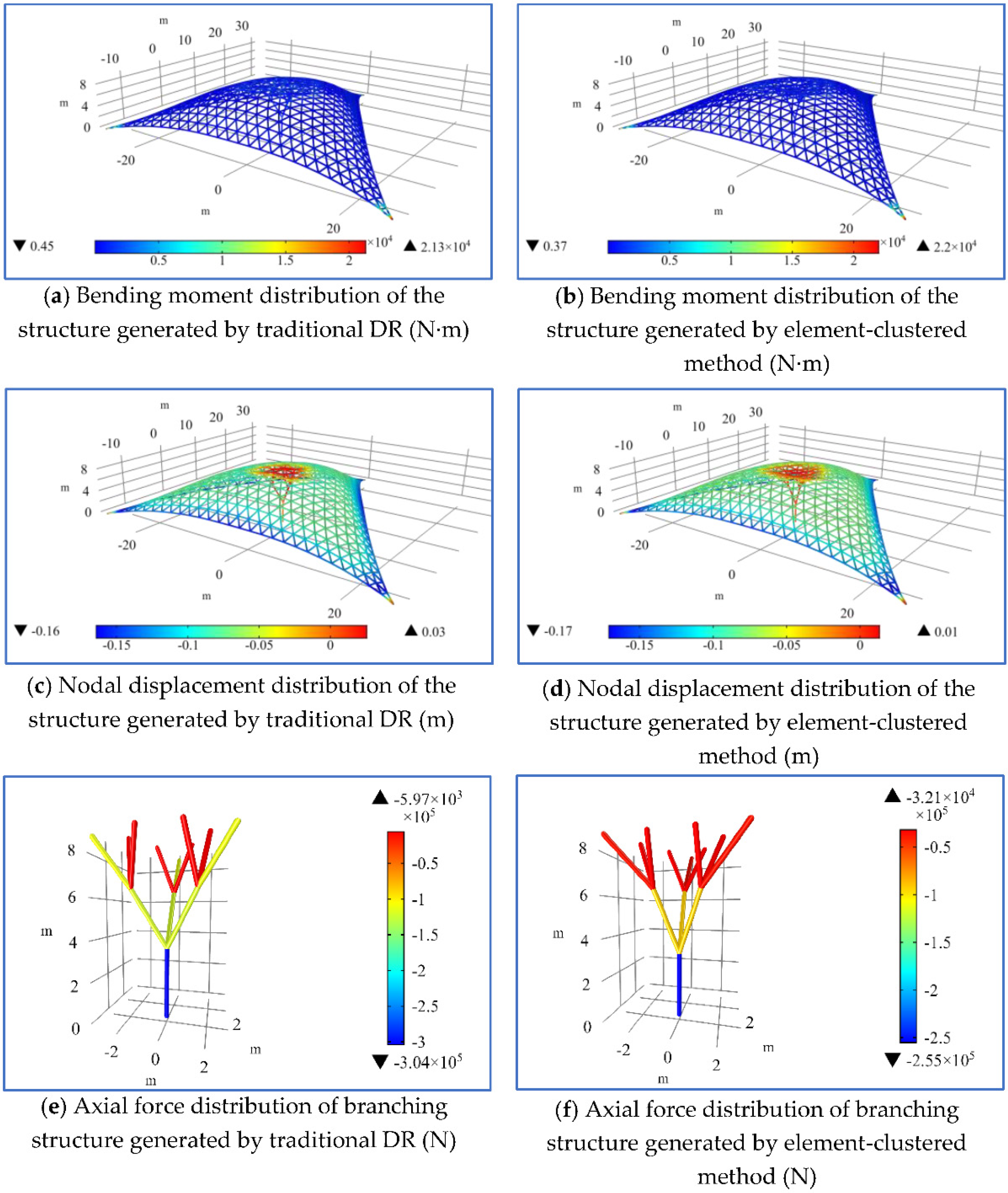
The finite element software COMSOL is used to analyze the mechanical performances of the two form-found structures. In the finite element analysis, it is assumed that the materials are linear elastic, the elastic modulus is 200 GPa, and the diameters of the members are 60 mm. The vertical downward load acting on each node of the latticed shell is 5 kN. The strain energy, nodal displacement, bending moment, and other mechanical performance indexes of the structure are shown in Table 2. It is easy to observe that the mechanical performances of the two structures are similar to the indexes shown in Table 2. Figure 4 shows the contours of nodal displacements, axis forces, and bending moments of the generated structures. Figure 5a,b shows the nodal displacement distributions of the two structures. Figure 5c,d shows the bending moment distribution of the two structures. It can be seen that the load is transferred mainly by axial forces. Figure 5e,f shows the axial force distributions of the two branching structures. The shapes and mechanical properties of the branching structures generated by the two methods are completely different. In the numerical hanging model, all nodes are hinged joints, while in the form-found structure, all nodes are rigid joints. The internal force distributions of the hanging model and the form-found structure are different due to their different connection modes. Although the axial forces of elements in the same cluster are equal when the hanging model reaches equilibrium, the axial forces of elements in the same cluster are redistributed in the corresponding structure.
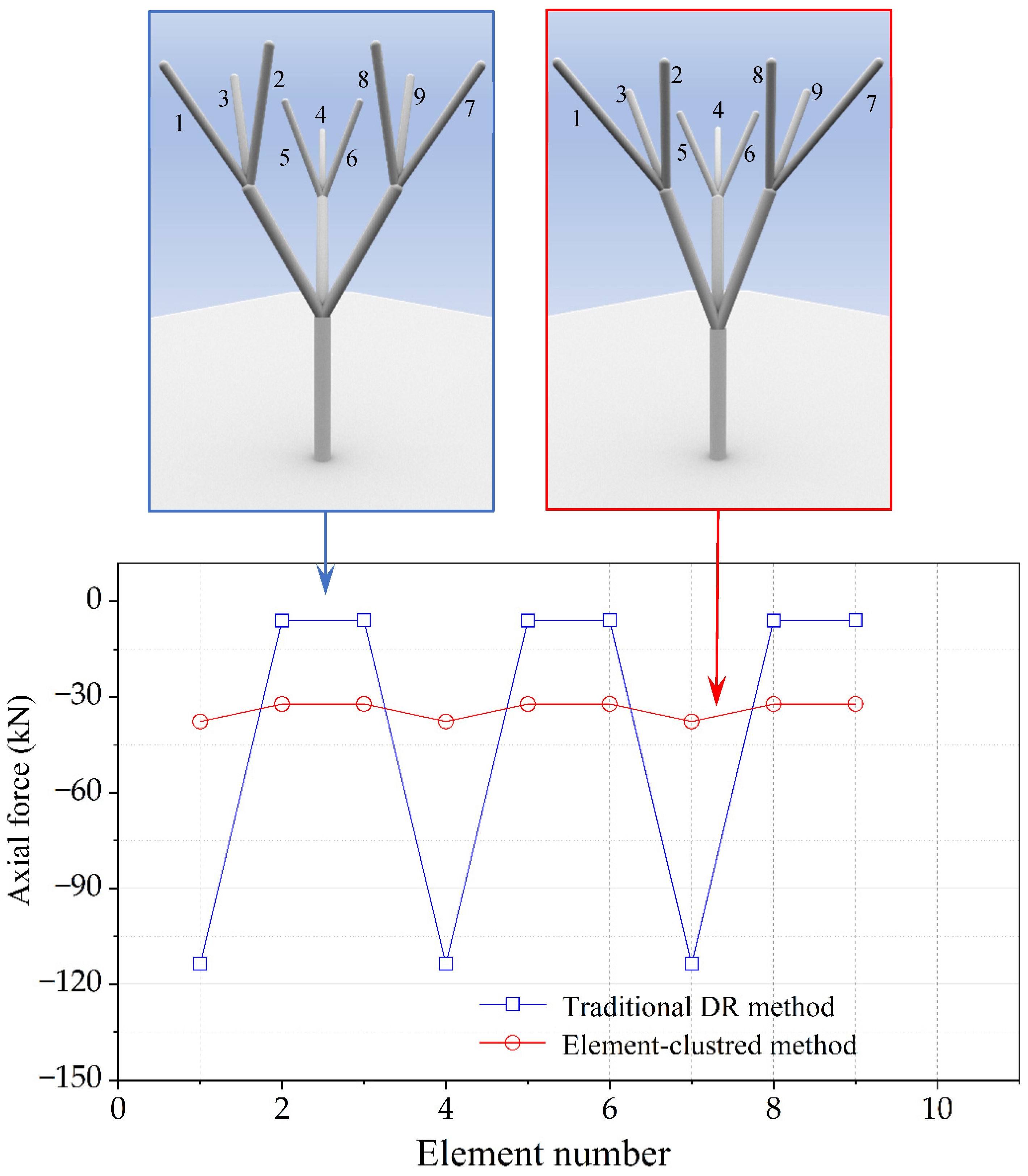
The axial force distributions of secondary branches of the branching structures were investigated. Figure 6 shows the axial force distribution of the members in second-level branches of the branching structures obtained by the two methods. According to the results, the axial force distributions of the branching structures obtained by the two methods are completely different. In the structure obtained by the traditional dynamic relaxation method, the maximum magnitude of axial compression force is 113.69 kN which occurs in members 1, 4, and 7 as shown in Figure 6 while the minimum magnitude of axial compression force is only 5.99 kN. In this generated structure, the axial forces of the second-level branches of the branching structure form a nonuniform distribution where the maximum magnitude and minimum magnitude of axial compression forces differ significantly based on the force simulation result, the members 2, 3, 5, 6, 8, 9 are determined as inefficient elements. In the structure generated by the element-clustered method, the axial forces of the members in the same level branches follow a near-uniform distribution. The maximum magnitude of axial compression force is 37.64 kN which occurs in members 1, 4, and 7 as shown in Figure 6, while the minimum magnitude of axial compression force is 32.15 kN. There is only a slight difference between the two extremes. In addition, there are no inefficient members whose axial forces are much smaller than others in the branching structures generated by the element-clustered method.
In the numerical example, the proposed element-clustered method can effectively prevent inefficient members existing in the form-found branching structure in the joint form-finding of the branching structure and latticed shell compared to the traditional dynamic relaxation method. Designers can achieve a near-uniform distribution of the axial forces of members in the same branching level through clustering elements, and thus this makes every element accountable and prevents the generation of inefficient members.
5. Conclusions
The “physical” and “numerical” hanging upside-down models are effective ways to determine the reasonable shapes of the latticed shells and branching structures. The dynamic relaxation method is one of the most effective form-finding methods to deal with this kind of problem. Based on the dynamic relaxation method, this paper proposed the element-clustered method for determining the rational shapes of branching structures. The proposed method clusters the elements and equalizes the axial forces of the elements in the same cluster, which can effectively eliminate slack elements in the model, and thus prevent the generation of inefficient members in the form-found branching structure. Two numerical examples are presented to illustrate the features of the proposed method and validate its effectiveness. Through the analysis of the generated structure, it is evident that the proposed method can effectively prevent the generation of inefficient members. Besides, different ways of clustering elements lead to different structural shapes, which can be used to adjust form-found shapes and provide more choices for structural designers. The comparison of the proposed element-clustered method and the dynamic relaxation method is also implemented. The more rational branching structural shape can be obtained through clustering elements, and this avoids the manual adjustment process when constructing the model and brings convenience to the form-finding of the branching structure. In addition, it is not difficult to combine the proposed method with other approaches in the form-finding of shells based on the dynamic relaxation, so it has a good application prospect. Numerical examples are provided to verify the effectiveness of the proposed method.
Author Contributions
Conceptualization, G.T. and C.C.; methodology, G.T.; software, Y.W.; validation, G.T., C.C., Z.G. and Y.W.; formal analysis, G.T.; investigation, C.C.; writing—original draft preparation, G.T.; writing—review and editing, Y.W.; funding acquisition, Z.G. All authors have read and agreed to the published version of the manuscript.
Funding
This research was supported by the Philosophy and Social Science Planning Project of Guangdong Province (No.GD19YGL08), the Humanities and Social Science Research Foundation of the Ministry of Education (NO.20YJC630026), and Guangdong Basic and Applied Basic Research Foundation (No.2020A1515110617).
Institutional Review Board Statement
Not applicable.
Informed Consent Statement
Not applicable.
Data Availability Statement
All data, models, and code generated or used during the study appear in the submitted article.
Conflicts of Interest
The authors declare no conflict of interest.
References
- Nerdinger, W.; Meissner, I.; Möller, E.; Grdanjski, M. Complete Works: Lightweight Construction—Natural Design; Birkhäuser: Berlin, Germany; Basel, Switzerland, 2005. [Google Scholar]
- Özdemir, N.B.; Selçuk, S.A. Tree metaphor in architectural design. Int. J. Archit. Urban Stud. 2016, 1, 64–76. [Google Scholar]
- Rian, I.M.; Sassone, M. Tree-inspired dendriforms and fractal-like branching structures in architecture: A brief historical overview. Front. Archit. Res. 2014, 3, 298–323. [Google Scholar] [CrossRef] [Green Version]
- Cui, C.; Jiang, B. A morphogenesis method for shape optimization of framed structures subject to spatial constraints. Eng. Struct. 2014, 77, 109–118. [Google Scholar] [CrossRef]
- Cui, J.; Zhou, G.; Ohsaki, M. Design of tree-type support structure of free-form shell generated using fractal geometry. In Proceedings of the IASS Annual Symposia, Tokyo, Japan, 26–30 September 2016. [Google Scholar]
- Bao, D.; Yan, X.; Snooks, R.; Xie, Y. Design and Construction of an Innovative Pavilion Using Topological Optimization and Robotic Fabrication. In Proceedings of the IASS Annual Symposia, Barcelona, Spain, 7–10 October 2019. [Google Scholar]
- Chen, Z.; Liu, H.; Wang, X.; Zhou, T. Establishment and application of cable-sliding criterion equation. Adv. Steel Constr. 2011, 7, 131–143. [Google Scholar]
- Zhang, Q.; Chen, Z.; Wang, X.; Liu, H. Form-finding of tree structures based on sliding cable element. J. Tianjin Univ. Sci. Technol. 2015, 48, 362–372. (In Chinese) [Google Scholar]
- Wu, Y.; Zhang, J.; Cao, Z. Form finding analysis and engineering application of branching structures. J. Build. Struct. 2011, 32, 162–168. (In Chinese) [Google Scholar]
- Wu, Y.; Xu, Y.; Li, Q. Effective length factors for branching structures. J. Build. Struct. 2018, 39, 53–60. (In Chinese) [Google Scholar]
- Eguchi, C.; Sugiura, N.; Tagawa, H. Architectural and Structural Design of Tree Structure Supporting Free-surface Shell Roof using Hanging Upside-down Model. In Proceedings of the IASS Annual Symposia, Boston, MA, USA, 16–20 July 2018. [Google Scholar]
- Eguchi, C.; Sugiura, N.; Tagawa, H. Proposal of design method of natural and rational tree-structure based on computational hanging upside-down simulation. In Proceedings of the IASS Annual Symposia, Barcelona, Spain, 7–10 October 2019. [Google Scholar]
- Zhao, Z.; Liang, B.; Liu, H.; Sun, Q. A novel numerical method for form-finding analysis of branching structures. J. Braz. Soc. Mech. Sci. Eng. 2017, 39, 2241–2252. [Google Scholar] [CrossRef]
- Barnes, M.R. Form finding and analysis of tension structures by dynamic relaxation. Int. J. Space Struct. 1999, 14, 89–104. [Google Scholar] [CrossRef]
- Richardson, J.N.; Adriaenssens, S.; Coelho, R.F.; Bouillard, P. Coupled form-finding and grid optimization approach for single layer grid shells. Eng. Struct. 2013, 52, 230–239. [Google Scholar] [CrossRef]
- Zhang, Y.; Chen, D.; Qian, H. Computational method for the deformation mechanism of non-prestressed cable net structures based on the vector form intrinsic finite element method. Eng. Struct. 2021, 231, 111788. [Google Scholar] [CrossRef]
- Su, Y.; Wu, Y.; Ji, W.; Shen, S. Shape Generation of Grid Structures by Inverse Hanging Method Coupled with Multi-objective Optimization. Comput.-Aided Civ. Infrastruct. Eng. 2018, 33, 498–509. [Google Scholar] [CrossRef]
- Yu, Y.; Paulino, G.H.; Luo, Y. Finite Particle Method for Progressive Failure Simulation of Truss Structures. ASCE J. Struct. Eng. 2011, 137, 1168–1181. [Google Scholar] [CrossRef] [Green Version]
- Hangai, Y.; Kawaguchi, K. Analysis of shape-finding process of unstable link structures. Bull. Int. Assoc. Shell Spat. Struct. 1989, 30, 116–128. [Google Scholar]
- Hangai, Y.; Wu, M. Analytical method of structural behaviours of a hybrid structure consisting of cables and rigid structures. Eng. Struct. 1999, 21, 726–736. [Google Scholar] [CrossRef]
- Zhang, T.; Kawaguchi, K.; Wu, M. A folding analysis method for origami based on the frame with kinematic indeterminacy. Int. J. Mech. Sci. 2018, 146–147, 234–248. [Google Scholar] [CrossRef]
Figure 1.
Shape schemes of different element clusters. (a) initial flexible model; (b) form-found shape of traditional DR method; (c,d) form-found shapes of element-clustered method.
Figure 1.
Shape schemes of different element clusters. (a) initial flexible model; (b) form-found shape of traditional DR method; (c,d) form-found shapes of element-clustered method.

Figure 2.
Initial hanging model.

Figure 3.
Comparison of the form-found structures. (a) the whole structure and (c) branching structure generated by traditional DR method; (b) the whole structure and (d) branching structure generated by element-clustered method
Figure 3.
Comparison of the form-found structures. (a) the whole structure and (c) branching structure generated by traditional DR method; (b) the whole structure and (d) branching structure generated by element-clustered method

Figure 4.
Comparison of the branching structures generated by two methods.

Figure 5.
Comparison of mechanical properties of form-found structures. Bending moment distributions of the structures generated by (a) traditional DR method and (b) element-clustered method; Nodal displacement distributions of the structures generated by (c) traditional DR method and (d) element-clustered method; Axial force distributions of branching structures generated by (e) traditional DR method and (f) element-clustered method.

Figure 6.
Comparison of axial forces in the members of branching structures.


Table 1.
Axial force of each element of the model in equilibrium state.
| Position of Elements | Shape Scheme I AF/N | Shape Scheme II AF/N | Shape Scheme III AF/N |
|---|---|---|---|
| Trunk | 100.00 | 100.00 | 100.00 |
| First-level branches | 28.631 | 35.970 | 35.988 |
| 68.901 | 35.992 | 35.914 | |
| 28.631 | 35.970 | 35.988 | |
| Second-level branches | 0.000 | 14.007 | 13.683 |
| 28.633 | 14.010 | 13.717 | |
| 0.002 | 13.995 | 13.688 | |
| 68.900 | 14.028 | 14.999 | |
| 0.001 | 14.008 | 15.006 | |
| 0.001 | 14.008 | 15.006 | |
| 0.000 | 14.007 | 13.683 | |
| 0.002 | 13.995 | 13.688 | |
| 28.633 | 14.010 | 13.717 |
Note: AF is the axial forces of the elements in the equilibrium model. The bold date represents the axial forces of the elements in the same cluster.
Table 2.
Mechanical properties of the generated structures.
| Mechanical Parameters | Structure Generated by Traditional DR | Structure Generated by Element Clustered Method |
|---|---|---|
| Average axial force | −89,737 N | −92,146 N |
| Average bending moment | 560.10 N·m | 491.49 N·m |
| Maximum axial force | −1.08 × 10⁶ N | −1.11 × 10⁶ N |
| Maximum bending moment | 21,285 N·m | 22,029 N·m |
| Average vertical displacement | −0.088 m | −0.089 m |
| Maximum vertical displacement | −0.164 m | −0.171 m |
| Strain energy | 94,825 N·m | 96,617 N·m |
Publisher’s Note: MDPI stays neutral with regard to jurisdictional claims in published maps and institutional affiliations. |
© 2021 by the authors. Licensee MDPI, Basel, Switzerland. This article is an open access article distributed under the terms and conditions of the Creative Commons Attribution (CC BY) license (https://creativecommons.org/licenses/by/4.0/).
Share and Cite
MDPI and ACS Style
Tu, G.; Chen, C.; Gong, Z.; Wang, Y. A Form-Finding Method for Branching Structures Based on Dynamic Relaxation. Appl. Sci. 2021, 11, 7165. https://0-doi-org.brum.beds.ac.uk/10.3390/app11157165
AMA Style
Tu G, Chen C, Gong Z, Wang Y. A Form-Finding Method for Branching Structures Based on Dynamic Relaxation. Applied Sciences. 2021; 11(15):7165. https://0-doi-org.brum.beds.ac.uk/10.3390/app11157165
Chicago/Turabian StyleTu, Guigang, Chen Chen, Zaijing Gong, and Yueren Wang. 2021. "A Form-Finding Method for Branching Structures Based on Dynamic Relaxation" Applied Sciences 11, no. 15: 7165. https://0-doi-org.brum.beds.ac.uk/10.3390/app11157165
Note that from the first issue of 2016, this journal uses article numbers instead of page numbers. See further details here.